the structure of the alphinizing coat on alloy steels · the structure of the alphinizing coat on...
TRANSCRIPT

A R C H I V E S o f
F O U N D R Y E N G I N E E R I N G
Published quarterly as the organ of the Foundry Commission of the Polish Academy of Sciences
ISSN (1897-3310)Volume 8
Issue 4/2008
229 – 235
43/4
A R C H I V E S o f F O U N D R Y E N G I N E E R I N G V o l u m e 8 , I s s u e 4 / 2 0 0 8 , 2 2 9 - 2 3 5 229
The structure of the alphinizing coat
on alloy steels
S. Pietrowski*, T. Szymczak Department of Materials Engineering and Production Systems, Technical University of Łódź
Stefanowskiego 1/15 St., 90-924 Łódź, Poland *Corresponding author. E-mail address: [email protected]
Received 10.07.2008; accepted in revised form 21.07.2008
Abstract
In this paper results of the structure of the coat alphinizing in AlSi5 silumin on alloy steels: acid-proof 1H18N9T (X6CrNiTi18-10) and high speed SW18 (HS18-0-1) were presented. The temperature of the alphinizing bath was amounts to750±5°C, and immersion time of the element τ = 180s. It was shown, that there is the different “g” coat thickness on testing steels. On the 1H18N9T steel it amounts to g = 52μm, and on the SW18 steel – g = 203μm. Regardless of a grade of testing alloy steels the coat consist of three layers with diversified phasic structure. There is different chemical composition of coat layers on testing steels. The first layer from the base consist of AlFe phase containing alloy addictions of steels: Cr and Ni (1H18N9T) and W, V and Cr (SW18). On this layer crystallize the second layer of intermetallic phases. It is the phase containing the main alloy addiction of steels: AlFeCr (1H18N9T) and AlFeW (SW18). The last, outside layer consist of silumin containing AlFeNi intermetallic phases on the 1H18N9T steel and AlFeW on the SW18 steel. Regardless of the grade of testing steels there is Si element in all layers of the coat. There are morphological differences in tested layers. The second layer (AlFeW phase) inside the coat on the SW18 steel consist of faced crystals growing into in outside silumin layer. On the 1H18N9T steel a boundary between transient and outside layer is more uniform. Free separations of intermetallic phases inside silumin layer on the 1H18N9T steel have lamellar and on the SW18 steel – faced form. Keywords: Innovative foundry technologies and materials, Alloy steels, Silumins, Alphinize, Layered casts, X-ray microanalysis
1. Introduction
In papers [1-9] the structure and crystallization model of alphinizing coat and layered cast on the unalloyed steel, nodular and grey cast iron were presented. It was shown, that alphinizing coat consist of four layer, in order from the base: Al3Fe, Al12Fe3Si2, Al9Fe3Si2 and silumin components α + (α + β).
The aim of this work was testing of the alphinizing coat structure on alloyed steels. Because of applied properties and possibilities using of layered product in machines construction to tests the acid-proof 1H18N9T (X6CrNiTi18-10) and high speed SW18 (HS18-0-1) steels were used.
2. Work methodology To research the acid-proof 1H18N9T (X6CrNiTi18-10) and
high speed SW18 (HS18-0-1) steels were used. Their chemical composition and microstructure were shown properly on Table 1 and in Figure 1(a-b).
Table 1. The chemical composition of tested alloy steels
Chemical composition, % Steel grade C Cr Ni Mn Ti W V 1H18N9T (X6CrNiTi18-10) ≤0,10 18,0 9,0 ≤2,0 5⋅C÷0,8 − −
SW18 (HS18-0-1) 0,80 4,0 − − − 18,0 1,25
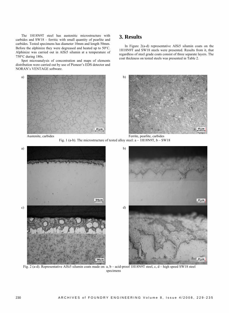
The 1H18N9T steel has austenitic microstructure with carbides and SW18 – ferritic with small quantity of pearlite and carbides. Tested specimens has diameter 10mm and length 50mm. Before the alphinize they were degreased and heated up to 50°C. Alphinize was carried out in AlSi5 silumin at a temperature of 750°C during 180s.
Spot microanalysis of concentration and maps of elements distribution were carried out by use of Pioneer’s EDS detector and NORAN’s VENTAGE software.
3. Results
In Figure 2(a-d) representative AlSi5 silumin coats on the 1H18N9T and SW18 steels were presented. Results from it, that regardless of steel grade coats consist of three separate layers. The coat thickness on tested steels was presented in Table 2.
a)
b)
Austenite, carbides Ferrite, pearlite, carbides
Fig. 1 (a-b). The microstructure of tested alloy steel: a – 1H18N9T, b – SW18
a)
b)
c)
d)
Fig. 2 (a-d). Representative AlSi5 silumin coats made on: a, b – acid-proof 1H18N9T steel, c, d – high speed SW18 steel
specimens
A R C H I V E S o f F O U N D R Y E N G I N E E R I N G V o l u m e 8 , I s s u e 4 / 2 0 0 8 , 2 2 9 - 2 3 5 230

Table 2. The coat thickness
Specimen material Coat thickness g, μm
1H18N9T (X6CrNiTi18-10) 52
SW18 (HS18-0-1) 203
Results from it that on the 1H18N9T austenitic steel formed the coat quadruple more thin than on the SW18 steel having microstructure alloyed ferrite with small quantity of pearlite and carbides. To determine the coat structure on tested steels distribution maps of steels and alphinizing bath elements and spot microanalysis of elements concentration were made. In Figure 3 the AlSi5 coat on the 1H18N9T steel was shown. It consist of three layers: transient, „g1” thick, where thin, „g1`” thick layer lying directly on steel can be isolated and outside, „g2” thick layer. „g1” thickness was assumed as an average value, which including irregularity of transient layer. The map of elements distribution: Al, Si, Ti, Cr, Fe and Ni in area from fig. 3 was presented in Figure 4. Results from it, that there is increased concentration of: Al, Si, Cr and Fe in transient layer of the coat. There is high and uniform Al concentration and in specified areas the increased concentration of Si, Fe, Ni and Ti elements in the outside layer.
Fig. 3. The alphinizing, „g” thick coat made on 1H18N9T steel with marked thicknesses of components layer: „g1`” – the layer lying directly on the steel, „g1” – transient layer, „g2” – outside
layer
In Figure 5 points 1-6 of the coat were shown, where spot microanalysis of elements concentration was made and its results were presented in Figure 6 (a-e).
Fig. 4. The map of elements concentration: Al, Si, Ti, Cr, Fe and Ni in the alphinizing coat on the 1H18N9T steel
A R C H I V E S o f F O U N D R Y E N G I N E E R I N G V o l u m e 8 , I s s u e 4 / 2 0 0 8 , 2 2 9 - 2 3 5 231
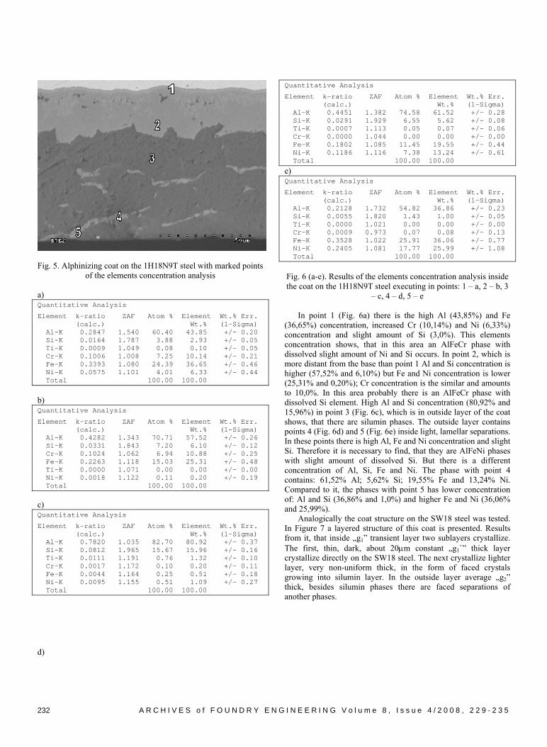
Fig. 5. Alphinizing coat on the 1H18N9T steel with marked points of the elements concentration analysis
a) Quantitative Analysis
Element k-ratio ZAF Atom % Element Wt.% Err. (calc.) Wt.% (1-Sigma) Al-K 0.2847 1.540 60.40 43.85 +/- 0.20 Si-K 0.0164 1.787 3.88 2.93 +/- 0.05 Ti-K 0.0009 1.049 0.08 0.10 +/- 0.05 Cr-K 0.1006 1.008 7.25 10.14 +/- 0.21 Fe-K 0.3393 1.080 24.39 36.65 +/- 0.46 Ni-K 0.0575 1.101 4.01 6.33 +/- 0.44 Total 100.00 100.00
b) Quantitative Analysis
Element k-ratio ZAF Atom % Element Wt.% Err. (calc.) Wt.% (1-Sigma) Al-K 0.4282 1.343 70.71 57.52 +/- 0.26 Si-K 0.0331 1.843 7.20 6.10 +/- 0.12 Cr-K 0.1024 1.062 6.94 10.88 +/- 0.25 Fe-K 0.2263 1.118 15.03 25.31 +/- 0.48 Ti-K 0.0000 1.071 0.00 0.00 +/- 0.00 Ni-K 0.0018 1.122 0.11 0.20 +/- 0.19 Total 100.00 100.00 c) Quantitative Analysis
Element k-ratio ZAF Atom % Element Wt.% Err. (calc.) Wt.% (1-Sigma) Al-K 0.7820 1.035 82.70 80.92 +/- 0.37 Si-K 0.0812 1.965 15.67 15.96 +/- 0.16 Ti-K 0.0111 1.191 0.76 1.32 +/- 0.10 Cr-K 0.0017 1.172 0.10 0.20 +/- 0.11 Fe-K 0.0044 1.164 0.25 0.51 +/- 0.18 Ni-K 0.0095 1.155 0.51 1.09 +/- 0.27 Total 100.00 100.00 d)
Quantitative Analysis
Element k-ratio ZAF Atom % Element Wt.% Err. (calc.) Wt.% (1-Sigma) Al-K 0.4451 1.382 74.58 61.52 +/- 0.28 Si-K 0.0291 1.929 6.55 5.62 +/- 0.08 Ti-K 0.0007 1.113 0.05 0.07 +/- 0.06 Cr-K 0.0000 1.044 0.00 0.00 +/- 0.00 Fe-K 0.1802 1.085 11.45 19.55 +/- 0.44 Ni-K 0.1186 1.116 7.38 13.24 +/- 0.61 Total 100.00 100.00
e) Quantitative Analysis
Element k-ratio ZAF Atom % Element Wt.% Err. (calc.) Wt.% (1-Sigma) Al-K 0.2128 1.732 54.82 36.86 +/- 0.23 Si-K 0.0055 1.820 1.43 1.00 +/- 0.05 Ti-K 0.0000 1.021 0.00 0.00 +/- 0.00 Cr-K 0.0009 0.973 0.07 0.08 +/- 0.13 Fe-K 0.3528 1.022 25.91 36.06 +/- 0.77 Ni-K 0.2405 1.081 17.77 25.99 +/- 1.08 Total 100.00 100.00
Fig. 6 (a-e). Results of the elements concentration analysis inside the coat on the 1H18N9T steel executing in points: 1 – a, 2 – b, 3
– c, 4 – d, 5 – e
In point 1 (Fig. 6a) there is the high Al (43,85%) and Fe (36,65%) concentration, increased Cr (10,14%) and Ni (6,33%) concentration and slight amount of Si (3,0%). This elements concentration shows, that in this area an AlFeCr phase with dissolved slight amount of Ni and Si occurs. In point 2, which is more distant from the base than point 1 Al and Si concentration is higher (57,52% and 6,10%) but Fe and Ni concentration is lower (25,31% and 0,20%); Cr concentration is the similar and amounts to 10,0%. In this area probably there is an AlFeCr phase with dissolved Si element. High Al and Si concentration (80,92% and 15,96%) in point 3 (Fig. 6c), which is in outside layer of the coat shows, that there are silumin phases. The outside layer contains points 4 (Fig. 6d) and 5 (Fig. 6e) inside light, lamellar separations. In these points there is high Al, Fe and Ni concentration and slight Si. Therefore it is necessary to find, that they are AlFeNi phases with slight amount of dissolved Si. But there is a different concentration of Al, Si, Fe and Ni. The phase with point 4 contains: 61,52% Al; 5,62% Si; 19,55% Fe and 13,24% Ni. Compared to it, the phases with point 5 has lower concentration of: Al and Si (36,86% and 1,0%) and higher Fe and Ni (36,06% and 25,99%).
Analogically the coat structure on the SW18 steel was tested. In Figure 7 a layered structure of this coat is presented. Results from it, that inside „g1” transient layer two sublayers crystallize. The first, thin, dark, about 20μm constant „g1`” thick layer crystallize directly on the SW18 steel. The next crystallize lighter layer, very non-uniform thick, in the form of faced crystals growing into silumin layer. In the outside layer average „g2” thick, besides silumin phases there are faced separations of another phases.
A R C H I V E S o f F O U N D R Y E N G I N E E R I N G V o l u m e 8 , I s s u e 4 / 2 0 0 8 , 2 2 9 - 2 3 5 232

Fig. 7. Alphinizing coat „g” thick made on the SW18 steel with marked thicknesses of components layers: „g1`” – the layer lying directly on the steel, „g1” – transient layer, „g2” – outside layer
Fig. 8. The map of the distribution: Al, Si, Ti, Cr, Fe and Ni elements inside the alphinizing coat on the SW18 steel
On the area showed in fig. 7 the distribution of elements: Al, Si, Ti, Cr, Fe and W was analyzed. Distribution maps of these elements was shown in Figure 8.
Results from it, that in transient layer there is higher concentration of: Al, Fe, W and Si. The outside layer consists of
hypoeutectic silumin phases. Measurement points 1-6 of elements concentration in the coat were shown in Figure 9. The elements concentration in points 1-6 is shown in Figure 10 (a-f).
A R C H I V E S o f F O U N D R Y E N G I N E E R I N G V o l u m e 8 , I s s u e 4 / 2 0 0 8 , 2 2 9 - 2 3 5 233

Fig. 9. Alphinizing coat on the SW18 steel with marked points of the elements concentration analysis
a) Quantitative Analysis
Element k-ratio ZAF Atom % Element Wt.% Err. (calc.) Wt.% (1-Sigma) Al-K 0.4162 1.388 72.25 57.77 +/- 0.26 Si-K 0.0331 2.013 8.00 6.66 +/- 0.14 V -K 0.0057 1.106 0.41 0.63 +/- 0.07 Cr-K 0.0161 1.055 1.10 1.70 +/- 0.09 Fe-K 0.2621 1.101 17.42 28.84 +/- 0.46 W -L 0.0285 1.542 0.81 4.39 +/- 0.87 Ti-K 0.0000 1.094 0.00 0.00 +/- 0.00 Ni-K 0.0001 1.108 0.01 0.01 +/- 0.17 Total 100.00 100.00
b) Quantitative Analysis
Element k-ratio ZAF Atom % Element Wt.% Err. (calc.) Wt.% (1-Sigma) Al-K 0.3848 1.307 68.37 50.30 +/- 0.23 Si-K 0.0550 1.812 13.01 9.96 +/- 0.16 V -K 0.0063 1.104 0.50 0.70 +/- 0.07 Cr-K 0.0160 1.056 1.19 1.68 +/- 0.09 Fe-K 0.1939 1.065 13.57 20.66 +/- 0.40 W -L 0.1127 1.478 3.32 16.65 +/- 1.94 Ti-K 0.0005 1.111 0.04 0.05 +/- 0.05 Ni-K 0.0000 1.058 0.00 0.00 +/- 0.00 Total 100.00 100.00
c) Quantitative Analysis
Element k-ratio ZAF Atom % Element Wt.% Err. (calc.) Wt.% (1-Sigma) Al-K 0.9624 1.011 98.67 97.31 +/- 0.40 Si-K 0.0032 2.452 0.77 0.79 +/- 0.08 V -K 0.0002 1.204 0.01 0.02 +/- 0.09 Cr-K 0.0013 1.171 0.08 0.15 +/- 0.10 Fe-K 0.0040 1.161 0.23 0.47 +/- 0.16 W -L 0.0071 1.614 0.17 1.14 +/- 1.04 Ti-K 0.0011 1.197 0.07 0.13 +/- 0.07 Ni-K 0.0000 1.149 0.00 0.00 +/- 0.00 Total 100.00 100.00
d) Quantitative Analysis
Element k-ratio ZAF Atom % Element Wt.% Err. (calc.) Wt.% (1-Sigma) Al-K 0.5909 1.203 80.62 71.07 +/- 0.34 Si-K 0.0434 2.112 9.98 9.16 +/- 0.25 V -K 0.0044 1.153 0.31 0.51 +/- 0.11 Cr-K 0.0031 1.109 0.20 0.34 +/- 0.13 Fe-K 0.1335 1.126 8.24 15.04 +/- 0.59 W -L 0.0246 1.572 0.64 3.86 +/- 1.50 Ti-K 0.0000 1.149 0.00 0.00 +/- 0.00 Ni-K 0.0002 1.123 0.01 0.02 +/- 0.27 Total 100.00 100.00
e) Quantitative Analysis
Element k-ratio ZAF Atom % Element Wt.% Err. (calc.) Wt.% (1-Sigma) Al-K 0.8553 1.020 89.84 87.27 +/- 0.38 Si-K 0.0416 2.269 9.33 9.43 +/- 0.24 V -K 0.0009 1.204 0.06 0.11 +/- 0.09 Cr-K 0.0022 1.169 0.13 0.25 +/- 0.11 Fe-K 0.0048 1.158 0.28 0.56 +/- 0.17 W -L 0.0148 1.608 0.36 2.38 +/- 1.18 Ti-K 0.0000 1.198 0.00 0.00 +/- 0.00 Ni-K 0.0000 1.144 0.00 0.00 +/- 0.00 Total 100.00 100.00
f) Quantitative Analysis
Element k-ratio ZAF Atom % Element Wt.% Err. (calc.) Wt.% (1-Sigma) Al-K 0.3887 1.313 69.75 51.04 +/- 0.27 Si-K 0.0468 1.826 11.21 8.54 +/- 0.21 V -K 0.0031 1.102 0.24 0.34 +/- 0.09 Cr-K 0.0195 1.054 1.46 2.05 +/- 0.12 Fe-K 0.1959 1.063 13.76 20.83 +/- 0.56 W -L 0.1148 1.475 3.40 16.94 +/- 1.45 Ti-K 0.0008 1.109 0.07 0.08 +/- 0.08 Ni-K 0.0017 1.051 0.11 0.18 +/- 0.23 Total 100.00 100.00
Fig. 10 (a-f). Results of the elements concentration analysis inside the coat on the SW18 steel executing in points: 1 – a, 2 – b, 3 – c,
4 – d, 5 – e
In point 1 (Fig. 10a), there is the high Al and Fe concentration (57,77% and 28,84%) and increased Si and W (6,66% and 4,39%). Therefore this layer probably consist of Al3Fe phase containing dissolved W and Si elements. In points 2 (Fig. 10b) Al and Fe concentration decreasing to 50,30% and 20,66%. W and Si concentration increases (16,65% and 9,96%). It is probably AlFeW phase with dissolved Si. In point 3 (Fig. 10c) there is high concentration only Al element (97,31%). It is probably α(Al) phase. The high concentration in point 4 (Fig. 10d) of: Al (71,07%), Fe (15,04%) and Si (9,16%) and increased W (3,86%) suggest, that it is AlFeSi phase with W element. Point 5 is probably located in α+β eutectic grain, what shows high Al and Si concentration (Fig. 9e). In point 6 (Fig. 10f) there is high concentration of: Al (51,04%), Fe (20,83%) and W (16,94%) and increased Si elements. Therefore it is probably AlFeW phase containing dissolved Si element (8,54%).
A R C H I V E S o f F O U N D R Y E N G I N E E R I N G V o l u m e 8 , I s s u e 4 / 2 0 0 8 , 2 2 9 - 2 3 5 234

In Figure 11 (a-c) the structure of alphinizing coat on the 45 (C45), 1H18N9T (X6CrNiTi18-10) and SW18 (HS18-0-1) steels is shown. Results from it, that on alloy steels, the first layer consist of AlFe phase containing steel alloy components. Adhere to them the layer consist of AlFe phase containing the main alloy
addiction i.e. AlFeCr and AlFeW phases. The next layer consist of silumin containing: AlFeNi intermetallic phases on the 1H18N9T steel and AlFeW phases on the SW18 steel. There is Si element inside phases of all layers, regardless of steel grade.
a) b) c)
Fig. 11 (a-c). The scheme of alphinizing coat structure on steel: a – 45, b – 1H18N9T, c – SW18
4. Conclusions
The results have indicated the following: − alloy addictions have essential influence on the structure and
thickness of alphinizing coat, − basic AlFe phase is the first layer on steel side, it is an Al3Fe
phase in unalloyed steel and in alloyed steels the layer containing alloyed components,
− in silumin layer there are AlFeNi and AlFeW phases containing Si element.
References [1] S. Pietrowski, Structure of alfinizing layer on the gray cast
iron, Archives of Foundry, No. 11, 2004 (in Polish). [2] S. Pietrowski, T. Szymczak, The structure of Al–Si
immersing coatings on iron alloys, Archives of Foundry, No. 12, 2004 (in Polish).
[3] S. Pietrowski, T. Szymczak, The structure of connection of alphinizing coat with silumin, Archives of Foundry, No. 14, 2004 (in Polish).
[4] S. Pietrowski, T. Szymczak, The influence of surface roughness on the coating thickness after alphinizing, Archives of Foundry, No. 17, 2005 (in Polish).
[5] S. Pietrowski, T. Szymczak, The influence of selected technological elements on the structure of alphinizing coat on iron alloys, Archives of Foundry, No. 19, 2006 (in Polish).
[6] S. Pietrowski, L. Klimek, T. Szymczak, Diffraction research of the alphinizing coat on iron alloys, Archives of Foundry, No. 22, 2006 (in Polish).
[7] S. Pietrowski, T. Szymczak, Crystallization model of layered cast through the alphinizing coat, Materials Engineering, No. 5, 2006, 1178-1183.
[8] S. Pietrowski, T. Szymczak, Effect of silicon concentration in bath on the structure and thickness of grey cast iron coating after alphinising, Archives of Materials Science and Engineering, vol. 28, issue 7, 2007, 29-33.
[9] T. Szymczak, Model of coat increase on iron alloys hot dip obtained in Al-Si bath and its connection with multicomponent silumins, PhD thesis, Technical University of Łódź, 2007.
A R C H I V E S o f F O U N D R Y E N G I N E E R I N G V o l u m e 8 , I s s u e 4 / 2 0 0 8 , 2 2 9 - 2 3 5 235