the structural progressive collapse bulletin series slab
TRANSCRIPT

C O N C R E T E R E I N F O R C I N G S T E E L I N S T I T U T E
THE STRUCTURALBULLETINSERIES
NUMBER 2
Steven M. Baldridge, P.E., S.E. andFrancis K. Humay, Ph.D., S.E.Baldridge & Associates Structural Engineering, Inc.
SLAB STEEL REINFORCEMENT
Reinforced Concrete and Secure Buildings:Progressive Collapse
TURKISH EMBASSY BUILDING, TURKEY

ContentsIntroduction . . . . . . . . . . . . . . . . . . . 2
What is Progressive Collapse? . . . . . . 3
Limitations of CurrentDesign Approaches . . . . . . . . . . . . . . 3
Existing Progressive Collapse Guidelines . . . . . . . . . . . . . . . . . . . . 4
Progressive Collapse Design & Analysis Procedures. . . . . . . . . . . . 5
Design Applications . . . . . . . . . . . 5
Removal of Structural Members. . . 5
Loading Criteria and Material Properties . . . . . . . . . . . . . . 6
Acceptance Criteria . . . . . . . . . . . . . . 6
Limits of Damage . . . . . . . . . . . . . 6
Examples of Progressive CollapseMitigation in Concrete Structures . . . 7
Removal of Interior Load-Bearing Wall (“BASE Hanger System”). . . . 7
Removal of Exterior Member (RC Slab Strengthening) . . . . . . . 10
Existing Mid-Rise Building (Progressive Collapse and Seismic Design) . . . . . . . . . . . . . . . 12
Detailing for Structural Integrity. . . . . . . . . . . . . 14
Reinforcement Detailing for Progressive Collapse . . . . . . . . . 15
Conclusions. . . . . . . . . . . . . . . . . . . 16
About The Authors . . . . . . . . . . . . . 16References . . . . . . . . . . . . . . . . . . . 16
There has been much debate over what changes, if any, should be made tobuilding codes and what types of buildings should be addressed. There is agree-ment, however, that engineers, as a matter of standard practice, should considerthe “load paths” within a structure and focus on tying individual structuralmembers together to improve a building’s overall integrity.
In light of recent world events, two major building owners, the GeneralServices Administration (GSA) and the Department of Defense (DoD) arerequiring engineers to consider building security as another design criterion. TheDepartment of Homeland Security is mandating greater security considerationsfor structures housing critical infrastructure. Even private sector owners anddevelopers of high-profile buildings are taking a closer look at security risks astheir buildings may be considered “targets” of both domestic and foreign terrorists.
Most engineers are experienced in designing structures to resist natural disasters such as hurricanes and earthquakes, but few are knowledgeable indesigning structures to meet requirements known as Antiterrorism/ForceProtection (AT/FP) standards. AT/FP covers a very broad range of disciplinesfrom site planning to mass notification systems. Of most interest to thoseinvolved with the structural design of buildings are the prevention of progressivecollapse and blast resistance.
Blast resistant design is a highly specialized field concerned with minimizing the hazards associated with intentional or accidental explosions. The general objective is to design a building to resist specified blast overpressures withinrequired performance limits. For antiterrorism considerations, the design explosion parameters are based on terrorist threat scenarios. Typical threat scenarios include means of delivery (i.e. vehicle bomb, placed bomb, mail bomb, etc.), weight of explosive and standoff distance (i.e. distance frombuilding to detonation). Unfortunately, the exact location, size and nature of terrorist threats are unpredictable.
Because it is impossible to design for every conceivable threat, the prevailingdesign philosophy is to allow local damage, but to mitigate the occurrence of progressive collapse. Progressive collapse is a condition where local failure leadsto resulting damage that is disproportionate to the damage that initiated the collapse. Prevention of progressive collapse is achieved by providing sufficientcontinuity, redundancy, and/or energy dissipation capacity in the structuralmembers and connections. Even where security concerns are not an issue,these concepts are essential to sound engineering practice.
There is a growing need to better educate the practicing engineer (and others in the construction industry) on the basic design principles associated with blastresistance and the prevention of progressive collapse. Although both of thesedesign scenarios concern the structural response to abnormal loading, theirincorporation into the design process present unique challenges. For this reason, and because of the considerable amount of information involved, itmakes sense to discuss these topics separately rather than combine them.
In the authors’ opinion, the mitigation of progressive collapse is a better starting point, because it is applicable to a greater number of buildings in boththe public and private sector. Furthermore, the fundamental concepts involvedwith progressive collapse mitigation are valuable to the design of almost allstructures. This Structural Bulletin, therefore, focuses on progressive collapsemitigation in reinforced concrete structures. The first section of the Bulletin provides a general discussion of the current approaches used to design for progressive collapse resistance. The middle portion includes specific projectsdesigned by the authors where reinforced concrete was used to mitigate thepotential for progressive collapse. At the end of the Bulletin, there is a discussion on reinforcing steel detailing requirements.
This publication is intended for the use of professionals competent to evaluate the significance and limitations of its contents and who will accept responsibility for the application of the material it contains. The Concrete ReinforcingSteel Institute reports the foregoingmaterial as a matter of information,and therefore, disclaims any and all responsibility for application of the stated principles or the accuracy of the sources other than material developed by the Institute.
Introduction
2
With the tragic attacks on the Murrah Federal Building and the WorldTrade Center towers, attention in the engineering community is againbeing focused on general structural integrity and design strategies forthe prevention of progressive collapse.

Concrete and Secure Buildings: Progressive Collapse
Limitations of Current Design Approaches
Progressive collapse increases the likelihood of greater human casualties and trapped survivors as a result of thecollapse. One of the more infamousexamples of progressive collapse is theAlfred P. Murrah Federal Building inOklahoma City (See Figure 1) whereapproximately 70% of the buildingexperienced dramatic collapse. It wasdetermined that most of the devastation,including the loss of 168 lives was theresult of progressive collapse, not thedirect effects of the explosion2.
On the other hand, a good example of a building that experienced extensivelocal damage, but did not experience progressive collapse, is the Khobar Towersin Saudi Arabia. The Khobar Towers losta significant area of its exterior framingdue to damage sustained from a large terrorist truck bomb attack. As is illustrated in Figure 2, there was significant local damage, but no progressivecollapse. This is a good example of abuilding that had incorporated many ofthe design concepts listed in ASCE 7-02’s“Guidelines for the Provision of GeneralStructural Integrity”.
These are basic principles, not driven by formulas or computers, that engineersshould conceptualize and consider in the process of designing any building. The American Concrete Institute recognized these principles with the additionof Section 7.13 “Requirements For Structural Integrity” to ACI 318-893. This recent section provided guidance on “minor changes in detailing of reinforcement” that would enhance the overall performance of the structure by improving its redundancy and ductility. While not requiring an explicit analysis, the intent is to increase the survivability of a structure in the event of damage to a major supporting element from an abnormal loading.
To actually analyze and design a building to prevent specific progressive collapse scenarios is a more complicated issue. Although defined in ASCE 7,there is still much debate over what constitutes progressive collapse. For example, was the initiating event at the Murrah Building truly a “local” failure?The truck bomb parked next to the building contained approximately 4,000pounds of fertilizer-based “ANFO” (ammonium nitrate/fuel oil) explosive. Theblast wave disintegrated one of the perimeter columns and caused brittle failureof two adjacent columns— approximately 120 linear feet of building perimeterwas supported by these columns. In order to design for prevention of progres-sive collapse, the concepts of “initial local failure” and “disproportionate”collapse must be more clearly defined.
The design approach to mitigate the potential for progressive collapse as a result of abnormal loading is not standardized in the United States. In general, current national buildings codes and standards either address progressive collapsein qualitative terms (i.e., by requiring designs to provide general structuralintegrity) or they do not broach the subject matter at all. Government agencies,however, tend to be more direct in handling progressive collapse. The GSA andthe DoD have developed criteria that do provide engineers with a prescriptiveprocedure to assess the susceptibility of a building to progressive collapse.
It should be emphasized that the GSA and DoD procedures are not predicatedon any specific abnormal loading or threat scenario. The “analytical” removal of a single column or beam from a building in a computer analysis does not necessarily represent a “real world scenario”. Instead, these analytical approachesare a method of providing sufficient redundancy, continuity, and/or energy dissipation capacity in the members and connections of a structure to allowalternate load paths to develop if local damage occurs. These procedures typically focus on the post-event capacity, ductility, and robustness of the individual members and connections compared with just key element resistance.
Designing for the mitigation of progressive collapse should not be confusedwith blast design or blast hardening of a structure. Blast design is a complicatedfield that requires the knowledge of a specific threat. The goal in blast hardeningis to prevent the blast from breaching the building’s envelope. Blast design caninclude analysis of not only the primary structural components, but also thebuilding’s windows, doors and facade.
Figure 1:ALFRED P.MURRAH
BUILDING,OKLAHOMA CITY
EXPERIENCED
PROGRESSIVE
COLLAPSE
Figure 2:KHOBAR TOWERS, SAUDI ARABIA.EXPERIENCED
SIGNIFICANT
DAMAGE TO THE
FACADE, BUT NO
PROGRESSIVE
COLLAPSE
What is Progressive Collapse?
3
ASCE 7-021 defines progressive collapse as “the spread of an initial local failure from element toelement resulting eventually, in thecollapse of an entire structure or adisproportionately large part of it.”
As a starting point, considering continuity, redundancy and ductility in structural design and detailing will lead to a more robust and resilient structure.
In the U.S. the approach to preventing progressive collapse is not clearlydefined. For example, the ASCE 7-02 provides a general discussion of progressive collapse in its commentary, but does not include any quantifiable or enforceable requirements.
Several government agencies such as the Department of Defense and the General Services Administration, on the other hand, have developed their own independent criteria. U.S. government facilities present highly visible targets for domestic or international terrorists, increasing the likelihoodof a potential attack with explosives or other damaging means. For this reason,the DoD and the GSA have realized the need to address progressive collapsemitigation in a more comprehensive manner. Although some of the particulardetails are different, many of the concepts used in the DoD’s standards are similar to those of the GSA.
Existing Progressive Collapse Guidelines
4
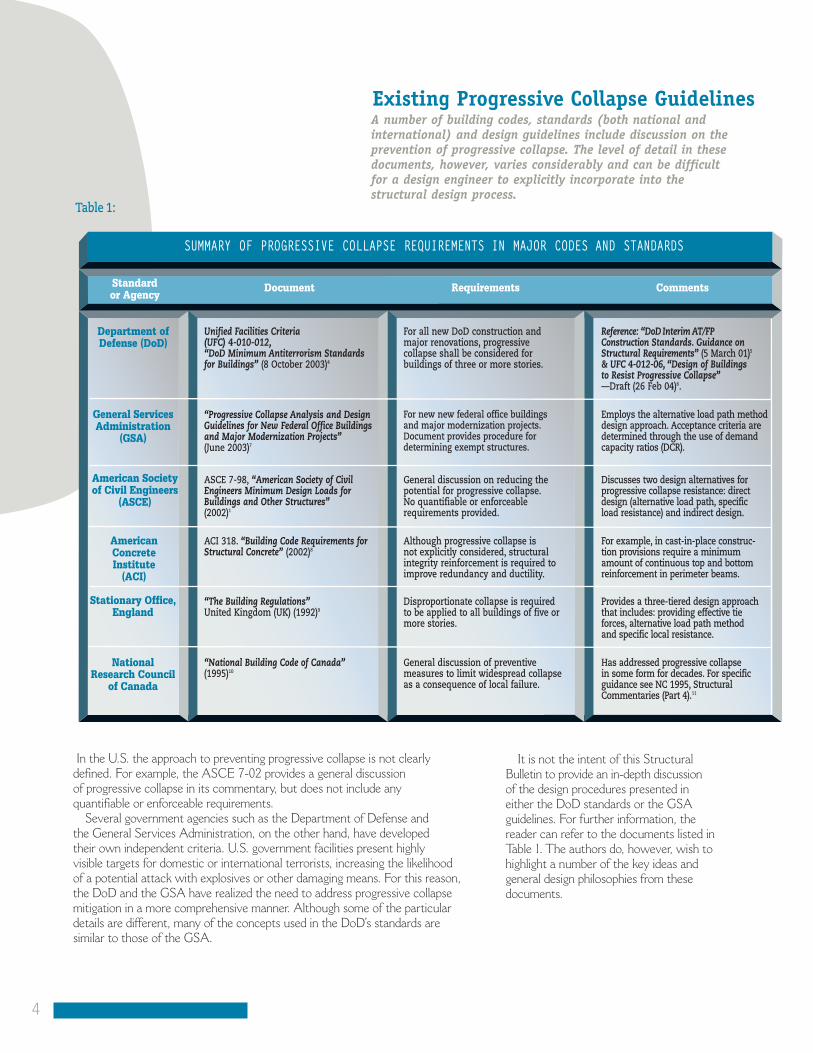
SUMMARY OF PROGRESSIVE COLLAPSE REQUIREMENTS IN MAJOR CODES AND STANDARDS
Standardor Agency
Document Requirements Comments
Unified Facilities Criteria (UFC) 4-010-012,“DoD Minimum Antiterrorism Standardsfor Buildings” (8 October 2003)4
For all new DoD construction andmajor renovations, progressive collapse shall be considered for buildings of three or more stories.
Reference: “DoD Interim AT/FP Construction Standards. Guidance onStructural Requirements” (5 March 01)5
& UFC 4-012-06, “Design of Buildings to Resist Progressive Collapse”—Draft (26 Feb 04)6.
“Progressive Collapse Analysis and DesignGuidelines for New Federal Office Buildingsand Major Modernization Projects” (June 2003)7
For new new federal office buildings and major modernization projects.Document provides procedure for determining exempt structures.
Employs the alternative load path methoddesign approach. Acceptance criteria aredetermined through the use of demandcapacity ratios (DCR).
ASCE 7-98, “American Society of CivilEngineers Minimum Design Loads forBuildings and Other Structures”(2002)1
General discussion on reducing thepotential for progressive collapse.No quantifiable or enforceable requirements provided.
Discusses two design alternatives for progressive collapse resistance: directdesign (alternative load path, specific load resistance) and indirect design.
ACI 318. “Building Code Requirements forStructural Concrete” (2002)8
Although progressive collapse is not explicitly considered, structural integrity reinforcement is required toimprove redundancy and ductility.
For example, in cast-in-place construc-tion provisions require a minimumamount of continuous top and bottomreinforcement in perimeter beams.
“The Building Regulations” United Kingdom (UK) (1992)9
Disproportionate collapse is requiredto be applied to all buildings of five ormore stories.
Provides a three-tiered design approachthat includes: providing effective tie forces, alternative load path method and specific local resistance.
“National Building Code of Canada”(1995)10
General discussion of preventive measures to limit widespread collapseas a consequence of local failure.
Has addressed progressive collapse in some form for decades. For specific guidance see NC 1995, StructuralCommentaries (Part 4).11
It is not the intent of this Structural Bulletin to provide an in-depth discussionof the design procedures presented ineither the DoD standards or the GSAguidelines. For further information, thereader can refer to the documents listed inTable 1. The authors do, however, wish tohighlight a number of the key ideas andgeneral design philosophies from thesedocuments.
A number of building codes, standards (both national and international) and design guidelines include discussion on the prevention of progressive collapse. The level of detail in these documents, however, varies considerably and can be difficult for a design engineer to explicitly incorporate into the structural design process.
Department ofDefense (DoD)
Table 1:
General ServicesAdministration
(GSA)
American Societyof Civil Engineers
(ASCE)
AmericanConcrete Institute
(ACI)
Stationary Office,England
National Research Council
of Canada

Progressive Collapse Design & Analysis Procedures
Design ApplicationsIn the direct design approach, there is anexplicit consideration of resistance to progressive collapse. Two methods representing the direct design approachare presented in the ASCE document: (1) the alternate path method, “a methodthat allows local failure to occur but seeksto provide alternate load paths so that thedamage is absorbed and major collapse is averted”; and (2) the specific localresistance method, “a method that seeksto provide sufficient strength to resist failure from accidents or misuse.” In theindirect design approach, progressive collapse mitigation is provided by ensuringminimum levels of strength, continuity,and ductility within the structural members and connections.
Currently, direct design, or specificallythe alternate path method, is the mostwidely used approach for explicitlyaddressing progressive collapse. Both theDoD standard and the GSA guidelines arebased on this procedure. It is interesting tonote, however, that the DoD approachappears to be changing quite significantly.The draft of UFC 4-012-06, “Design ofBuildings to Resist Progressive Collapse,”
6
uses an approach similar to the BritishStandard. In the British Standard, a combined approach of both direct andindirect design is used. Under the proposednew UFC, a combination of indirectdesign, the alternate path method, and thespecific local resistance method would beused. The specific analysis method wouldultimately depend on the level of protectiondesired and whether it is new or existingconstruction. The examples provided inthis bulletin were designed using the alternate path method.
Concrete and Secure Buildings: Progressive Collapse5
Aside from the more prescriptive design approaches mentioned, the ASCEcommentary also provides discussion about “good” design practices that will result in a more robust structure. Examples include: good plan layout,returns on walls, changing directions of the floor slab span, load-bearing interiorpartitions, catenary action of floor slab, and beam action of walls. Considerationof these design practices encourages engineers to better understand how a struc-ture will likely behave and predict the performance under an extreme event.
There is no consensus among those in the engineering community on the“best” approach for dealing with progressive collapse. The limited number ofactual progressive collapse failures has made some engineers question if a nationalcodified standard is even necessary. Most will agree, however, that incorporating“good” design practices, as described above, will enhance a building’s performanceunder abnormal loading. Typically, these modifications can be achieved in cast-in-place monolithic reinforced concrete (RC) buildings with little impact on overall cost.
Removal of Structural MembersThe minimum requirement of the DoD standards and GSA guidelines is
to ensure a building can withstand the loss of one primary exterior vertical or horizontal load bearing member without progressive collapse. Interior memberremoval is only required if a specific threat or risk exists—such as a parkinggarage being located beneath a building. The designer is required to go aroundthe exterior perimeter of the building envelope removing a single member at a time and evaluating the effects. Selection of the appropriate members is dependent on the structural framing system used and can include columns,beams, bearing walls, or slabs.
At first, this process may appear overwhelming since most buildings havehundreds (if not thousands) of individual structural members (i.e., beams,columns, walls, etc.). However, for most typical structures, the number of cases that actually need to be evaluated is a small fraction of the total number of members. Careful selection of critical members and a good understanding of anticipated alternate load paths will help to greatly reduce the number of cases to consider. For example, on relatively simple layouts, the GSA limits the number of cases that must be checked. At each floor, the loss of a column shallbe considered at the following locations: (1) near the middle of the building’sshort side; (2) near the middle of the building’s long side; and (3) at the corner.
Although the speed at which a member is removed has no impact on a staticanalysis, it may have a significant impact on a dynamic analysis. The verticalmember that is removed should be removed instantaneously, which in the case of a dynamic analysis should occur over a time period that is no more than 1/10 of the period associated with the structural response mode for the vertical member removal. Based on the GSA guidelines, columns are to be analytically
removed directly below the joint (i.e., withoutdamaging the joint) as illustrated in Figure 3.The initial damage assumed by this approach is a simplifying assumption that does not correspond to any specific threat (or abnormal load case).
The ASCE 7-02 standard describes two design approaches for dealing with progressive collapse: direct design and indirect design.
Original StructureConfiguration
Incorrect ColumnRemoval
Correct ColumnRemoval
Figure 3: GSA APPROACH FOR REMOVING A COLUMN

The DoD standard, for example,requires that the following factoredload combination be applied to theentire structure.
P = 1.0D + 0.5L + 0.2W whereD = Dead LoadL = Live Load W = Wind Load
On the resistance side of the equation, it is also important to modelmaterial strength as accurately as possible. In order to account for material over-strength as well as strainhardening, an over-strength factor isusually permitted. For RC structuresthe GSA document allows anincrease factor of 1.25 for both concrete compressive strength andreinforcing steel ultimate tensile andyield strength. Although previousversions of the DoD standard onlypermitted a 10% increase for theseproperties, the draft version of UFC4-012-06 (26 February 2004) followsthe GSA guidelines.
Acceptance Criteria
To limit the possibility of collapse, the DoD provides maximum allowable ductility and/or rotation limits for most structural members. These empiricallydetermined damage criteria are for typical elements in conventional construction(i.e., construction that has not been hardened to resist abnormal loading). Asillustrated in Table 2, the response limits for RC construction are dependent onthe type of member being analyzed and the detailing of the reinforcing steel.
Once the model is analyzed with the proper member removed, the remainingmembers should be checked for both strength and deformation. The exact procedure will depend on whether a linear elastic or non-linear method is usedfor the analysis. In the DoD approach, if the shear capacity (or response limit) of a member is exceeded, the member is considered a failed member. Any deadand live loads associated with a failed member should be distributed to othermembers in the same story or to members in the story below. Where the loadfrom the failed member is imparted to members in the story below, it must beincreased to account for the dynamic impact of the falling debris.
The general philosophy for the GSA guidelines is similar to that of the DoD. One main difference, however, for linear elastic methods, is that the GSA usesthe Demand-Capacity Ratio (DCR) concept found in seismic rehabilitation toassess the likelihood for progressive collapse. The analysis procedure prescribedin the GSA guidelines is similar to the “m-factor” method currently used inFEMA 27313 elastic methods.
Original Design
Spandrelbeams sizeand capacitiesmoderatelyincreased
(improvements distributed evenly over the entire height)
Spandrelbeams sizeand capacitiessignificantlyincreased
(improvements concentrated on the 2nd and 3rd floor level)
Limits of DamageAs indicated by ASCE’s definition of progressive collapse, some “initial local failure”is acceptable. ASCE 7-02, however, does not clearly define the acceptable limit of“local failure.” Both the GSA guidelines and the DoD standard attempt to place aquantifiable limit on the maximum amount of damage that can be sustained underthe instantaneous removal of a single load-bearing member. If the analysis indicatesthat the collapsed area will extend beyond these limitations, the structure is consid-ered non-compliant and the design must be revised and the analysis repeated. Themaximum allowable extent of collapse for an exterior threat shall be confined to thesmaller of the following.
GSA requirements:1. The structural bays directly associated with the removed vertical member in the floor
directly above the removed member.
2. 167 m2 (1,800 ft2) at the floor level directly above the removed vertical member.
6
Loading Criteria and Materials PropertiesTo avoid an overly conservativedesign, it is recognized that fulllive load is unlikely to occur at the same time as an extraordinaryevent. For this reason, the factoredload combinations for design typically represent a realistic prediction of the actual loads on a structure.
The acceptance criteria specified in the draft proposal of the UFC 4-012-06 specifies that in determining the design strength (i.e., fMn and fVn) for RC members the nominal strengths shall be calculated in accordance with ACI 318-02. All f-factors are equal to1.0 except for shear where f = 0.75. Maintaining f = 0.75 for shear is stipulated because shear failures are known to be sudden and occur in a brittle manner.
Redesign - Option 1 Redesign - Option 2
Figure 4:GSA REDESIGN APPROACH TO MITIGATE
PROGRESSIVE COLLAPSE

Concrete and Secure Buildings: Progressive Collapse7
Designing to mitigate the potential for progressive collapse is a relativelynew concept for the majority of engineers in the U.S. For any givenbuilding, there are various ways to achieve resistance to progressive collapse. The purpose of the following example projects is to illustratedifferent approaches for mitigating progressive collapse in reinforcedconcrete structures and to highlight a number of key design considerations.
Removal of Interior Load-Bearing Wall (“BASE Hanger System”)Through extensive experience with Department of Defense projects, the authorshave come to realize that the increased emphasis on creating security enhancedbuildings has not come with a proportional increase in project funding. In light ofthis, the importance of selecting an efficient and economical structural systemhas become even more vital to ensuring a successful project.
In the authors’ opinion, progressive collapse should be considered as early inthe design phase as possible. One excellent method of efficiently addressing thenew progressive collapse requirements is through a “multi-hazard” approach. In this approach, a single structural system is selected that can resist the forcesassociated with various hazards (i.e., wind, seismic, progressive collapse, etc.).The following example illustrates an innovative application of this approach for a 5-story reinforced concrete dormitory.
The floor layout, typical of residential or dormitory type construction, isshown in Figure 5. In plan, the structure is approximately 73 m (240 ft.) long x 17.7 m (58 ft.) wide. The building has a central corridor with living units oneach side. The typical unit width and hence the distance between load-bearingwalls is approximately 4.95 m (16.25 ft.). The main structural system consists of 165 mm (6.5 in.) thick RC one-way and two-way slabs supported on 203 mm (8 in.) thick interior RC partition walls. Use of reinforced concrete for the primaryload-resisting elements was a requirement of the Military.
Design of this project was required to conform to the Interim DoD AT/FPConstruction Standards (16 December 1999)14 and the DoD Interim AT/FPConstruction Standards, Progressive Collapse Design Guidance (4 April 2000)15.As previously discussed, the minimum progressive collapse standards are typicallyconcerned with removal of external members. The criterion for this building,however, was even more stringent than the minimum standards. It specified the removal of all vertical load-bearing elements that are within 3 m (10 ft.) (i.e., the floor-to-floor height) from the exterior perimeter of the building. For load-bearing walls, this distance was also required to be no less than the distance to the first vertical construction joint.
Progressive collapse mitigation is achieved through the use of load-bearing partition walls, referred to as the “BASE Hanger System”. The interior partitionwalls are divided into two distinct and separate vertical members, an “exterior”and an “interior” (See Figures 6 and 7). The separation between the two wallsconsists of a 610 mm (24 in.) weakened or “fuse” section of wall, 305 mm (12 in.)
DoD requirements:1. 70 m2 (750 ft2) at the floor area directly
above and directly below the removed member.
2. 15% at the floor area directly above and directly below the removed member.
3. In no case shall the predicted damage extendbeyond the bays associated with the removedwall or column.
If the damage is analytically determined toextend beyond the above limits, the structureis considered to have a high potential for pro-gressive collapse and must be redesigned. Asindicated in Figure 4, there are a number ofapproaches for improving a structure’s abilityto resist the required “missing column” sce-nario. The most appropriate solution should also consider architectural constraints, constructibility, and overall cost. Equallyimportant, the modifications for progressivecollapse should be compatible with the struc-tural design for other hazards. For example,redesign Option 2 illustrated in Figure 4 mayhave a negative impact on seismic perform-ance. If the frame in question is a momentframe, this local increase in beam size maycreate an undesirable “weak column-strongbeam” condition. Although an analytically acceptable solution, concentrating the “pro-gressive collapse resistance” at the bottom ofa structure, as indicated in Option 2, may notbe the most desirable alternative. Unlike theapproach illustrated in Figure 3, damage sus-tained during an abnormal loading is not pre-dictable and may propagate into the beam. Ifit occurs, local beam damage increases thepotential for progressive collapse more signifi-cantly in the structural system illustrated inredesign Option 2 as compared to that inredesign Option 1.
Examples of Progressive Collapse Mitigationin Reinforced Concrete Structures
Table 2:
REINFORCED CONCRETE (RC) MEMBER DUCTILITY AND ROTATION LIMITS5
Component*
RC Beam 60
RC Beam One-Way Slabs 60
(without tension membrane)
RC Beam One-Way Slabs 120
(with tension membrane)
RC Beam Two-Way Slabs 60
(without tension membrane)
RC Beam Two-Way Slabs 120
(with tension membrane)
RC Columns (tension controls) 60
RC Columns (compression controls) 1RC Frames 20 Sidesway
< H/25
Ductility (u) Rotation( º )l Notes
-
*Provide shear stirrups per requirements of DAHSCWE Manual12
where rotation >20.
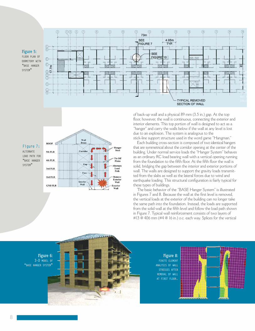
of back-up wall and a physical 89 mm (3.5 in.) gap. At the topfloor, however, the wall is continuous, connecting the exterior andinterior elements. This top portion of wall is designed to act as a“hanger” and carry the walls below if the wall at any level is lostdue to an explosion. The system is analogous to the stick-line support structure used in the word game “Hangman.”
Each building cross-section is composed of two identical hangersthat are symmetrical about the corridor opening at the center of thebuilding. Under normal service loads the “Hanger System” behavesas an ordinary RC load bearing wall with a vertical opening runningfrom the foundation to the fifth floor. At the fifth floor the wall issolid, bridging the gap between the interior and exterior portions ofwall. The walls are designed to support the gravity loads transmit-ted from the slabs as well as the lateral forces due to wind andearthquake loading. This structural configuration is fairly typical forthese types of buildings.
The basic behavior of the “BASE Hanger System” is illustratedin Figures 7 and 8. Because the wall at the first level is removed,the vertical loads at the exterior of the building can no longer takethe same path into the foundation. Instead, the loads are supportedfrom the solid wall at the fifth level and follow the load path shownin Figure 7. Typical wall reinforcement consists of two layers of#13 @ 406 mm (#4 @ 16 in.) o.c. each way. Splices for the vertical
Figure 5:FLOOR PLAN OF
DORMITORY WITH
“BASE HANGER
SYSTEM”
8
Figure 2KHOBAR TOWE
SAUDI ARABI
EXPERIENCE
SIGNIFICANT
TO THE FACA
BUT NO PRO
COLLAPSE
Figure 8:FINITE ELEMENT
ANALYSIS OF WALL
STRESSES AFTER
REMOVAL OF WALL
AT FIRST FLOOR.
Figure 6:3-D MODEL OF
“BASE HANGER SYSTEM”
Figure 7:ALTERNATE
LOAD PATH FOR
“BASE HANGER
SYSTEM”

Figure 9:WALL
REINFORCEMENT
AT FIRST
FLOOR OF
“BASE HANGER
SYSTEM”
wall reinforcement are staggered at 1219mm (4 ft.) o.c., and continuous hangerreinforcement (Dywidag Threadbars)and tie-off plates are added to help sup-port the slabs and distribute the tensionstresses introduced into the wall. At thevery top of the wall an additional (2) -#19 (#6) horizontal bars are added toresist the flexural stresses in the deepcantilever member.
In order to fully separate the interiorand exterior portions of the wall, a physical 76 mm (3 in.) gap runs theheight of the wall up to the fifth floor. In addition to the gap, a 610mm (2 ft.)long by 89mm (3.5 in.) wide section ofexpanded polystyrene is sandwichedwithin the concrete. The polystyrene is added to act as a “fuse” that helps dissipate the energy from the blast loadbefore it reaches the interior wall (See Figures 9 and 10).
Although not required by the DoDStandards, the BASE Hanger Systemremains within the elastic range ofbehavior. A maximum vertical deflectionof approximately 13 mm (0.5 in.) wascalculated using cracked section properties of the concrete. In addition,the inherent redundancy in the “BASEHanger System” actually allows morethan one wall to be removed withoutprogressive collapse. It is important tonote that the security provided by the“BASE Hanger System” was achievedwith a mere premium of roughly 3% ofthe overall construction cost of thestructure. Furthermore, the “BASEHanger System” did not have anyimpact on the architectural integrity of the project.
Concrete and Secure Buildings: Progressive Collapse9
Progressive Collapse Scenario:
Mitigation Approach:
Key Design Considerations:
Cost/Architectural Impact:
Removal of 3m length of interior load-bearing wall.
Alternate load path provided by deep cantilevered wall members (i.e. “BASE Hanger System”).
Continuity of vertical reinforcing steel to transfer tension stresses.Physical separation of “interior” and “exterior”portions of wall.
Roughly 3% increase in structural cost/no architectural impact.
2:ERS, IA.D
T DAMAGE
ADE, OGRESSIVE
Figure 10:DETAIL OF
SEPARATION BETWEEN
INTERIOR AND
EXTERIOR PORTION OF
WALLS.

At the ends of the building (last two bays), the slab thickness is increased to165mm (6.5 in.) for progressive collapse mitigation. The main partition walls run in the transverse direction and are spaced at approximately 3.7 m (12 ft.).The RC walls in the longitudinal direction are located primarily along the corridor. Because of the modular layout of the units, the RC slab behaves primarily as a one-way system between the transverse walls and more as a two-way system at the central corridor.
The unique layout and architectural features of this building required theremoval of (1) several columns at the front entrance and (2) portions of the load-bearing exterior walls at both ends of the structure. Because the bay spansin this building are relatively short, the floorslabs are capable of providing an alternate load path primarily through bending. As indicated in Figure 11, theamount of reinforcing steel in the end bays of the building needed to be increasedin specific areas. For practical purposes, the slab thickness was also increased by13 mm (0.5 in.) in these locations to accommodate the additional reinforcingsteel.
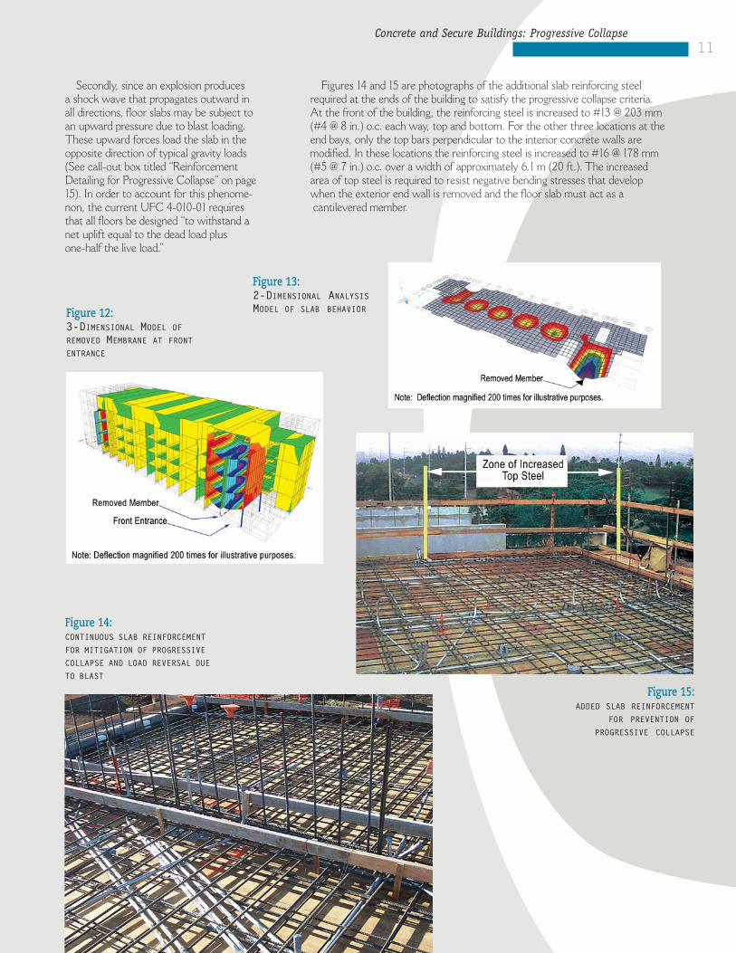
After removal of an external column, the floor slabs are designed to span over the removed member without experiencing collapse (See Figures 12 and 13).The enhancements to the building are distributed uniformly over the height ofthe structure, similar to re design Option 1 in Figure 4. For the particular building geometry and progressive collapse criteria, this proved a very efficientsolution. Yes, the floor slabs needed to be thickened and additional slab reinforcingsteel added. However this work was limited to isolated areas at the ends of the building and had negligible impact on the overall cost of the structure.
The typical slab reinforcement is #13 @ 203 mm (#4 @ 12 in.) o.c. each way top and bottom. The reinforcing steel is continuous in both directions andlap splices are staggered a minimum of 1217 mm (4 ft.). Continuity of the slabreinforcing steel is important for a number of reasons.
First, with continuous (or properly spliced) reinforcing steel and adequateanchorage into supports or adjacent members tensile membrane behavior candevelop. It has been shown that the ultimate capacity and the response limit of RC slabs can be greatly enhanced by membrane action. Although tensilemembrane behavior will most probably be accompanied by severe damage, thislevel of performance is acceptable if collapse is prevented.
Removal of Exterior Member (RC Slab Strengthening)The building structure for this secondexample is fairly similar to the dormitorybuilding discussed in the previous section.For a number of reasons, however, the progressive collapse analysis and mitigationapproach is significantly different in thisexample. First, based on the request forproposal (RFP) criteria, only an externalexplosive threat needed to be considered.Unlike with the “BASE Hanger System”,no portion of the interior transverse wallsneeded to be removed. This removal criterion is consistent with the latest version of the DoD Minimum AT/FPStandards (UFC 4-010-01). Secondly,because of architectural constraints, thewalls at the front entrance to the buildingcould not be made continuous to the foundation. These discontinuous walls aretherefore supported on exterior columns (or narrow widths of wall). The progressivecollapse review included an independentanalysis for the removal of each of thesecolumns.
Similar to the previous example, this dormitory structure is also five stories inheight with overall plan dimensions of 56m(184 ft.) x 17m (56 ft.) (See Figure 11). The typical floor framing consists of 152mm(6 in.) thick cast-in-place RC slabs support-ed by 152mm (6 in.) thick load-bearing concrete partition walls.
10
Progressive Collapse Scenario:
Mitigation Approach:
Key Design Considerations:
Cost/Architectural Impact:
Removal of exterior wall/column members at ends of building.
Alternate load path provided by reinforced concrete slab.
Increase thickness (i.e. 13mm)of floor slab at ends of building. Provide additionalslab reinforcing steel at ends of building.
Roughly 3% increase in structural cost/no architectural impact.
Figure 11:FLOOR PLAN OF DORMITORY WITH
ADDED SLAB REINFORCING STEEL
Concrete and Secure Buildings: Progressive Collapse11
Secondly, since an explosion produces a shock wave that propagates outward inall directions, floor slabs may be subject toan upward pressure due to blast loading.These upward forces load the slab in theopposite direction of typical gravity loads(See call-out box titled “ReinforcementDetailing for Progressive Collapse” on page15). In order to account for this phenome-non, the current UFC 4-010-01 requiresthat all floors be designed “to withstand a net uplift equal to the dead load plus one-half the live load.”
Figure 14:CONTINUOUS SLAB REINFORCEMENT
FOR MITIGATION OF PROGRESSIVE
COLLAPSE AND LOAD REVERSAL DUE
TO BLAST
Figure 15:ADDED SLAB REINFORCEMENT
FOR PREVENTION OF
PROGRESSIVE COLLAPSE
Figure 13:2-DIMENSIONAL ANALYSISMODEL OF SLAB BEHAVIORFigure 12:
3-DIMENSIONAL MODEL OF
REMOVED MEMBRANE AT FRONT
ENTRANCE
Figures 14 and 15 are photographs of the additional slab reinforcing steelrequired at the ends of the building to satisfy the progressive collapse criteria. At the front of the building, the reinforcing steel is increased to #13 @ 203 mm(#4 @ 8 in.) o.c. each way, top and bottom. For the other three locations at theend bays, only the top bars perpendicular to the interior concrete walls are modified. In these locations the reinforcing steel is increased to #16 @ 178 mm(#5 @ 7 in.) o.c. over a width of approximately 6.1 m (20 ft.). The increased area of top steel is required to resist negative bending stresses that develop when the exterior end wall is removed and the floor slab must act as acantilevered member.

12
Existing Mid-Rise Building(Progressive Collapse and Seismic Design)
To demonstrate this point, the authors performed a study of a 12-story reinforced concrete moment frame building that wasdesigned to the seismic provisions of the 1991 Uniform BuildingCode (UBC)16. It was demonstrated that based on the GSA criteria, progressive collapse is unlikely to occur with the prescribedcolumn removal. The seismic detailing of the reinforcing steel in the exterior moment frames allows for load reversal in the beamsspanning over the removed column. For a more detailed discussion,see the article entitled, “Preventing Progressive Collapse inConcrete Buildings,” Concrete International (November 2003)17.
An efficient and cost-effective structure can often be achievedby designing one system to simultaneously provide resistance tomultiple hazards (i.e., seismic, wind, and progressive collapse). This concept is clearly illustrated in the aforementioned ConcreteInternational article.
Another project completed by the authors, the major renovationof a 16-story mid-rise dormitory for the DoD, demonstrates howgood seismic detailing in RC structures can also help mitigate progressive collapse. One of the requirements of UFC 4-010-01 is that the implementation of the AT/FP standards, including the mitigation of progressive collapse, is mandatory for “all DoD building renovations, modifications, repairs, and restorations wherethose costs exceed 50% of the replacement cost of the building.”As with seismic retrofits, upgrading an existing building for progressive collapse mitigation can be both a technically challenging and costly process. For this reason, it is important to model the as-built conditions of the existing structure as completely and accurately as possible. In many instances,a more refined analysiscan be the difference between finding that a building meets the criteria versus recommending a costly and unnecessary retrofit.
A preliminary security analysis of the existing structure revealeda number of locations that appeared susceptible to progressive collapse. One area of concern was a narrow section of exteriorload-bearing wall that occurs in approximately ten locations aroundthe perimeter of the building (See Figure 16). In the case that thiswall is removed, an alternate load path needs to be provided for thegravity loads previously supported by this member. One potentialalternate load path that is readily apparent is through the RC floorslabs. If the RC slabs at each floor level can support the load overthe removed wall as a cantilevered member, progressive collapsecan be prevented. Unfortunately, the floor slabs are only designedto resist gravity loads and, therefore, do not have adequatestrength or the proper detailing required to act as cantileveredmembers.
Upon review of these results, it appeared that some type ofstrengthening would be required to meet the progressive collapse
Buildings designed with an adequate level of continuity, redundancy, and/or energy dissipation capacity — typical of buildings in seismic regions — have an inherent ability to develop alternative load paths and better mitigate progressive collapse.
Figure 16:PROPOSED PROGRESSIVE COLLAPSE
MITIGATION OPTION FOR
EXISTING MID-RISE BUILDING.

Progressive Collapse Scenario:
Mitigation Approach:
Key Design Considerations:
Cost/Architectural Impact:
Removal of existing load-bearing RC wall.
Option 1: Add interior walls solely for progressive collapse mitigation.
Option 2: Existing seismic link beam provides alternate load path.
Option 1: Labor intensive process to infill existing openings.
Option 2: Define existing conditions and provide refined analysis.
Option 1: Roughly $750,000/infillexisting openings.
Option 2: No cost impact/No aesthetic impact.
criteria. One proposal, as indicated inFigure 16, was to infill the existing opening between the exterior walls and the interior load-bearing walls withconcrete. The new RC wall would becast-in-place and tied to the existing concrete with epoxy dowels. In the casethat a portion of the exterior wall is lostduring an extreme event, the new concrete wall behaves as a deep cantilever member transferring anyunsupported loads back into the interiorwall. Although this is a technically soundoption, the existing conditions and themagnitude of the retrofit made it a verydifficult and costly solution.
As with most retrofit projects, one ofthe most difficult tasks is determining thedetails of the existing structural framing.A comprehensive review of the originalstructural drawings indicated a deep cast-in-place roof parapet around theperimeter of the building. Interestingly, in certain locations this beam was fairlylarge, 610mm (2 ft.) wide x 1829mm (6 ft.) deep, and heavily reinforced. Uponfurther investigation it was determinedthat this parapet was actually a “link”beam used to tie together adjacent concrete walls for lateral load resistance.Although not originally intended to resistprogressive collapse, it was demonstratedthrough a 3-dimensional finite elementanalysis that this “link” beam provides anadequate alternate load path if the wall in question is removed (See Figure 16).
This project indirectly illustrates both the importance of “good” seismicdetailing and the potential benefits ofhaving a structural system that is capableof resisting multiple hazards. True, a“multi-hazard” approach that includedprogressive collapse was not consideredfor the original design of this building.However, the current progressive collapse analysis demonstrates the efficiency that can be achieved if the“multi-hazard” approach is used. Without the deep upturned roof beam at the perimeter of the building, an expensive and potentially intrusive retrofit would have been required tomeet the progressive collapse criteria.
Figure 17:EXISTING
ALTERNATE
LOAD PATH
FOR MISSING
WALL SCENARIO
Concrete and Secure Buildings: Progressive Collapse13

Detailing for Structural Integrity
Although the examples presented in thisBulletin describe Department of Defenseprojects, it is important to note that the general design philosophies are applicable to all buildings. For the design of any RCstructure, engineers should be aware of the concepts of redundancy, continuity, and energy dissipation. Although not asexplicit as in the DoD standard or the GSA guidelines, ACI 318 does address the prevention of progressive collapse.
ACI 318 includes provisions for enhancingthe overall integrity of a structure underunforeseen loading conditions. Section 7.13 -Requirements for structural integrity of ACI318-02 represents an in direct approach todealing with progressive collapse. This isemphasized in the Commentary to Section7.13 that states, “It is the intent of this section of the code to improve the redundancyand ductility in structures so that in the eventof damage to a major supporting element or an abnormal loading event, the resultingdamage may be confined to a relatively small area…”
The provisions of Section 7.13 provide a number of rather simple detailing requirements for the reinforcing steel thathelp tie the structure together to provideresistance to progressive collapse. In the2002 code, the use of mechanical or weldedsplices for splicing reinforcement is now permitted to meet the structural integrityrequirements. Also in 2002 the provisions for the stirrups enclosing the continuity steel were revised. The code requires eitherU-stirrups with no less than 135-deg hooksaround the continuous top steel or one-piececlosed stirrups. This change was adopted toeliminate the use of two-piece closed stirrupsbecause the top crosstie is ineffective inrestraining the top continuous bars frompulling out of the top of the beam. Table 3and Figure 18 provide a summary of the ACI requirements for structural integrity.
For the design of any RC structure,engineers should be aware of the concepts of redundancy, continuity,and energy dissipation.
ACI 318-02 STRUCTURAL INTEGRITY REQUIREMENTS
Member Section Reinforcement Requirements1 Splice Location andAnchorage Requirements
Joist 7.13.2.1
One continuous bottom bar. Splice steel at or near support. Provide standardhook at non-continuoussupport.
Table 3:
Continuous top bars; 1/6 of steel required for negative moment at support (2 bars min.)
Splice steel at mid-span.Provide standard hook atnon-continuous support.
PerimeterBeam
7.13.2.2&
7.13.2.3Continuous bottom bars; 1/4 of steel required for positive moment at mid-span (2 bars min.)
Splice steel at or nearsupport. Provide standardhook at non-continuoussupport and at change inbeam depth.
All continuity steel shall beenclosed by U-stirrups orone-piece closed stirrups.
U-stirrups and one-piececlosed stirrups shall have hooks no less than 135-deg.
Beam(otherthan
perimeter)
7.13.2.4
When stirrups, as definedfor perimeter beams arenot provided, 1/4 of bottombars required for positivemoment at mid-span shallbe continuous (2 bars min.)
Splice steel at or nearsupport. Provide standardhook at non-continuoussupport and at change inbeam depth.
Two-WaySlab
7.13.2.5
All bottom bars with column strip in ea.direction shall be continuous. At least 2 barsshall pass through column.
Splice steel at or nearsupport per Fig 13.3.8.Provide standard hook atnon-continuous support.
Figure 18:PERIMETER BEAM REINFORCEMENT DETAILING PER ACI 318-02
STRUCTURAL INTEGRITY REQUIREMENTS
14
*All splices to provide continuity shall be Class A tension lap splices,or mechanical or welded splices satisfying 12.14.3.

One key aspect in designing for progressive collapse resistance in reinforced concrete structures is the proper structural detailing of reinforcing steel. Since this design dealswith extreme events, it is often assumed that the structure will deform well into the inelastic range. Special consideration must be given to reinforcement continuity, lap slices and anchorage so that the assumed alternate load paths are indeed provided.Continuity of slab reinforcement is an important aspect not only when designing for progressive collapse, but also when designing for the upward pressures occurring due to a blast scenario.
Reinforcement Detailing for Progressive Collapse
DETAIL FOR GRAVITY LOAD DETAIL FOR CONTINUITY AND PROGRESSIVE COLLAPSE
GRAV
ITYLOADS
BLAST
LOADING
PROG
RESS
IVE
COLL
APSE
NEG. MOMENTREGION
PLACEMENT OF LONG. REBAR FOLLOWS MOMENT DISTRIBUTION
*NOTE: STRUCTURAL INTEGRITY STEEL ASMAY BE REQ’D. BY ACI 318 NOT SHOWN.
POS. MOMENTREGION
NEG. MOMENT REGION
CLOSELY SPACEDSTIRRUPS
POS. MOMENTREGION
CONT.TOP &BOT.REBAR
NEG. MOMENT REGIONINCREASED NEG.MOMENT AS MEMBERMUST SPAN TWOBAYS
POS. MOMENTREGION
LOSS OFPRIMARY SUPPORT
POTENTIAL FORSUDDEN, BRITTLEFAILURE
LACK OF CONT.BOt. REBAR
Alternate Load Path Not Provided
NEG.MOMENT REGION CLOSELY SPACED STIRRUPS ENHANCEDUCTILITY
CONT.BOT.REBAR PROVIDES POS.MOMENT CAPACITY
LOSS OFPRIMARYSUPPORT
POS. MOMENTREGION
Alternate Load Path Provided
POS. MOMENTREGION
NEG. MOMENTREGION
NO REBAR TO RESISTLOAD REVERSAL
BLASTBLAST
Member Cannot Resist Upward Forces
CONT. REBAR RESISTSLOAD REVERSAL
BLAST
Member Can Resist Upward Forces
POS. MOMENTREGION
NEG.MOMENTREGION
CLOSELY SPACED STIRRUPS ENHANCE DUCTILITY
BLAST
Concrete and Secure Buildings: Progressive Collapse15

ASCE 7-02 Minimum Design Loads for Buildings and Other Structures,American Society of Civil Engineers, Reston ,VA, 2002.
FEMA – 277, The Oklahoma City Bombing: Improving BuildingPerformance Through Multi-Hazard Mitigation, Federal EmergencyManagement Agency, August 1996.
ACI 318, Building Code Requirements for Structural Concrete andCommentary, American Concrete Institute, Farmington Hills, MI, 1989.
Unified Facilities Criteria (UFC) 4-010-01, Department of Defense MinimumAntiterrorism Standards for Buildings, Department of Defense, October 2003.
Department of Defense Interim AT/FP Construction Standards, Guidance onStructural Requirements, Department of Defense, March 2001.
Unified Facilities Criteria (UFC) 4-012-06, Design of Buildings to ResistProgressive Collapse – Draft, Department of Defense, February 2004.
Progressive Collapse Analysis and Design Guidelines for New Federal OfficeBuildings and Major Modernization Projects, General ServicesAdministration, June 2003.
ACI 318, Building Code Requirements for Structural Concrete, AmericanConcrete Institute, Farmington Hills, MI, 2002.
The Building Regulations, Stationery Office, England 1992.
National Building Code of Canada, National Research Council of Canada, 1995.
Structural Commentaries (Part 4), NCA, National Research Council of Canada, 1995.
Army TM5-855-1, Air Force AFPAM 32-1147 (I), Navy NAVFAC P-1080,and DSWA DAHSCWEMAN-97, Design and Analysis of HardenedStructures to Conventional Weapons Effects, August 1998.
FEMA-273, NEHRP Guidelines for the Seismic Rehabilitation of Buildings,Federal Emergency Management Agency, Oct. 1997.
Department of Defense, Interim Antiterrorism/Force Protection ConstructionStandards, Department of Defense, December 1999.
Department of Defense, Interim Construction Standards, Progressive CollapseDesign Guidance, Department of Defense, April 2000.
Baldridge, S. and Humay F., “Preventing Progressive Collapse in Concrete Buildings”, Concrete International, Vol. 25, No. 11, November 2003, pp. 73–79.
Uniform Building Code (UBC), International Conference of Building Officials, Whittier, CA, 1991.
Funding for production of this CRSI Structural Bulletinwas provided by the California Field Iron WorkersAdministrative Trust, A Union Trust Fund.
The existing standards and guidelines for the mitigation of progressive collapse discussed in this Bulletin providegood tools for dealing with typical, fairly “regular”buildings. Unfortunately many of today’s buildings are not very “regular” and may be difficult to directly analyzewith these documents. Furthermore, there may be some disagreement among members of the engineeringcommunity as to the “exact” methodology that should beadopted for progressive collapse. With regard to differingopinion, no matter what approach is used, basic conceptssuch as continuity, redundancy, and energy dissipation arekey properties that will enhance the performance of anybuilding. Understanding these concepts will help designersdevelop a confidence for how a building behaves. Althoughthe authors understand the importance of sophisticated computer software, they also believe that the most powerful computer is no substitute for having a “goodengineering understanding” of structural behavior.
As illustrated in the referenced examples, the monolithicnature of cast-in-place reinforced concrete structuresmake the material inherently well suited for preventingprogressive collapse. Typically, enhanced continuity, redundancy, and energy dissipation can all be readilyachieved with simple modifications and attention to structural detailing of reinforcement. Progressive collapse is a design criterion that should be considered as early as possible in the design process.
A good understanding of concepts, such as alternateload paths, will help in the selection and configuration ofthe structural system. If done properly, the mitigation ofprogressive collapse in RC structures does not significantlyimpact the overall cost of a project.
Conclusions References
NOTICE TO READERSThis Bulletin is intended as a medium for free exchange of structural design ideasamong practicing Engineers. The ideas so expressed are the authors’. Publicationdoes not constitute endorsement by CRSI except as a meriting serious consideration.Readers are encouraged to submit discussion which may corroborate, contradict,limit, expand or improve application of the original papers. Submit discussions to:David P. Gustafson, Technical Director, Concrete Reinforcing Steel Institute, 933 N.Plum Grove Road, Schaumburg, IL 60173
Steven M. Baldridge, P.E., S.E. is President of Baldridge &Associates Structural Engineering, Inc., Honolulu, HI. Hereceived his BS from the University of Wisconsin, Madison, WI, and his MS from the University of Texas, Austin, TX. Mr. Baldridge has over 20 years experience and is a member of numerous professional societies including his appointment as a Director of Applied Technology Council (ATC). He has been a leader and innovator in addressing AT/FP requirements for both new and existing buildings.
Francis K. Humay, PhD, S.E. is an Associate with Baldridge and Associates Structural Engineering, Inc., Honolulu, HI. He received his BS from the University of Illinois at Urbana-Champaign; his MS from Stanford University, Stanford, CA;and his PhD from Rice University, Houston, TX. He has been extensively involved with military projects requiring the application of AT/FP and progressive collapse mitigation. In addition, he volunteers as a structural specialist for the Hawaii State Civil Defense US&R team.
ABOUT THE AUTHORS
933 N. Plum Grove Road • Schaumburg, Illinois 60173-4758Phone: 847-517-1200 • Fax: 847-517-1206 • Website: www.crsi.org
C O N C R E T E R E I N F O R C I N G S T E E L IN S T I T U T E