the sportplane builder - freea.moirier.free.fr/train d'atterrissage/train tricycle/train... ·...
TRANSCRIPT

GEAR RETRACTIONDETAILS
THESPORTPLANEBUILDER
By Antom (TonyI BmgelisEAA Detiignee Program Advisor
8509 Greenflint LaneAustin, Texas 78759
E YOU DECIDE to equip your airplane with aretractable gear, no blank piece of paper, no tablecloth,or napkin will ever again be safe from your sketchesand doodles of retractable gear details. I dare say thatby the time the gear construction is underway you willhave become thoroughly familiar with the theory of fold-ing landing gear mechanisms. After that, all that re-mains is the job of changing theory to substance by con-structing it and making it work smoothly and consis-tently (ha!). Simple paper sketches often fail to conveythe complexity of construction, alignment and adjust-ment. This is uniquely true when you undertake to de-velop a retractable gear installation in an airplane orig-inally designed for a fixed gear.
Modifying an airplane that you had no part in de-signing must never be taken lightly. Sure, a few build-ers have successfully done so, but even most of themexpress doubts that they would ever again attempt sucha conversion. They say it is not worth the effort; thatyou would often find yourself rebuilding as much as 50percent of the structure, and with each part made andinstalled, some other part would have to be moved, re-moved or redesigned . . . all of which in turn forced stillother changes. Weeks would often stretch into monthsand what had originally seemed to be a simple under-taking drags out for a year or more . . . sometimes withdisappointing results. Sounds discouraging, doesn't it?But, let's take an objective look and see what is reallyinvolved in building a retractable gear installation; andthen, you decide for yourself.
The Gear LegsRetractable gear legs (struts) are no different than
those used in fixed gear installations. I've seen oleostruts, slab spring gear legs, Wittman whip-rod legs,and welded steel tube truss gear legs all successfullymodified for retraction. So, the type of gear leg usedshould not, of itself, present an insurmountable conver-sion problem to a determined builder.
Far better than building the entire gear would bethe acquisition and adaptation of stock gear legs (com-plete with the retraction mechanism) removed fromsome demised type-certificated aircraft. Since a lot ofmachine shop work would ordinarily go into a retract-able gear, this acquisition would eliminate most of thatexpensive work.
Builders, being an innovative lot, have cannibalizedand used assemblies from aircraft like the Culver, Nav-ion, the Piper Arrow and others. This approach, how-ever, is frought with difficulties and can sometimes re-sult in a botched-up structure much less a botched-uplanding gear weighing more, and costing much more,than if the builder had stayed with the designer's origi-nal plans.
40 MARCH 1980
The view is from the front of the spar. The gear is down andthe lock (A) is not yet engaged. Retraction lever is againstthe stop bracket (B), a little more adjusting is needed here.
Note that this is a rear view of the gear position shown inphoto #1. To the left is the heavy garage door spring whichhelps in raising the gear. On the right is the worm gear as-sembly with the torque tube running to the cockpit manualretract ratchet.
The Jack PointsSometime during construction you have to decide
where to install three external jack points. Yes sir! Twojack points are not enough, not for a retractable gearairplane. The three jack points are as necessary as arethree special (tall) jacks which will be used henceforthto provide the means for raising the aircraft highenough to clear the landing gear for retraction testing,not only during construction but later for the annual in-spections.
You may even have to modify three regular jacks sothat the aircraft can be raised high enough.

If the jack points are not properly located on the air-craft, you might have to attach weights to the tail-endor tie it down to keep the airplane from tilting . . . it alldepends on the location of the main jack points. Re-member too, retraction tests will have to be performedat least annually.
The TrunnionsIn order to make a gear leg retractable, its upper end
must be attached to some sort of a trunnion. Unlike theattachment bracket which immobilizes the fixed gear legto the structure, the trunnion provides the support andpivot axis necessary in a retractable installation. Atrunnion suspends the gear, usually between the mainspar and an auxiliary spar.
You might get lucky and locate a couple of stocktrunnion castings which could be adapted to the gearlegs you will be using, otherwise you will have to fabri-cate your own. Anyway, not all aircraft ut i l ize cast-a l u m i n u m trunnions . . . some, l ike the BeechcraftBonanza, stay with the sturdy built-up welded steel tubetrusses. Constructing this type structure is well withinthe capabilities of the average builder.
Some designs incorporate a large tube welded to theupper gear leg. It serves as a trunnion and pivot axis forthe gear leg. This suspension method is often used inlightweight retractables, but because only one end of theinstallation is supported, it can result in unusual loadsbeing imposed on the spar. Not only is a large holethrough the spar necessary to accommodate it ... thespar and the adjoining structure must be beefy enoughto take the landing and taxiing stresses. If your spar de-sign cannot accommodate such a large hole, or if thehole must be drilled too close to the top or bottom edgesof the spar, a failed spar could be the future consequence. . . and what if that should happen in flight? Certainly,a careful calculation should first be made to determine ifthe spar can handle this type of installation.
Let me interject a note of caution by saying, no build-er should attempt to install a retractable gear that re-quires modification of essential structure without firstworking a stress analysis for the change. Of course, eachbuilder must evaluate his own qualifications in this re-gard if he intends to decide on his own whether or nothis changes will weaken the structure.
If welding is necessary to modify the attachmentarea of the gear legs, there will always be the risk thatthe oleo mechanism could become damaged or distorted.On the other hand, shock struts utilizing coil springs in-stead of oleos are less sensitive to the effects of distor-tion from welding. Nevertheless, the welds must be goodand the distortion must be controlled within acceptablelimits. The alignment of each attachment point is al-ways critical because some gear installations cannotbe adjusted for toe-in or toe-out once completed and in-stalled.
Shock Struts and ScissorsSince any good retractable gear will have some shock
absorbing capability, this provision can sometimes re-sult in conflicting measurements. For example, the gearlegs will ordinarily measure longer when retracted thanwhen under load on the ground. The wheel-well dimen-sions and even their shape and location should take thisinto account. Don't let your first retraction test surpriseyou with a gear that won't fit into the wheel wells.
The primary function of a scissors assembly is tohold the wheel in correct alignment and to keep it fromswiveling like a bar stool.
The scissors may be positioned as necessary duringconstruction to keep them from protruding when re-
This is a front view of the gear in the partially retracted posi-tion. (A) and (B) make up the down lock assembly. (C) is theheavy reinforcement plate for the spar. (F) is the swivel axisfor the retraction linkage and (D) is the trunnion axis. Gearinstallation requires a large hole through the spar.
A rear view of the partially raised gear as shown in Photo#3. (F) torque tube to cockpit ratchet. (A) is the worm gearassembly, (C) lever bolted to the trunnion is connected tothe heavy spring to ease retraction chore. (B) is the rearreinforcement plate for the spar/gear assembly.
Here is a pair of side mounted scissors. Note the externalrebound spring arrangement on the opposite side of thestrut.
tracted, or from interfering with any of the aircraftstructure. Scissors do not have to be located in front orback of the strut. A number of aircraft have themsituated on one side or other. This determination, how-ever, will have to be made prior to the jigging and weld-ing.
SPORT AVIATION 41
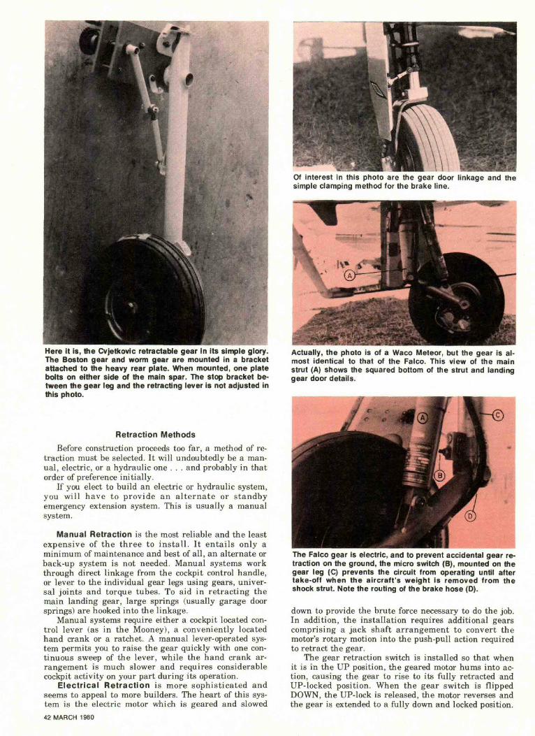
Here it is, the Cvjetkovic retractable gear in Its simple glory.The Boston gear and worm gear are mounted in a bracketattached to the heavy rear plate. When mounted, one platebolts on either side of the main spar. The stop bracket be-tween the gear leg and the retracting lever is not adjusted inthis photo.
Retraction MethodsBefore construction proceeds too far, a method of re-
traction must be selected. It will undoubtedly be a man-ual, electric, or a hydraulic one . . . and probably in thatorder of preference initially.
If you elect to build an electric or hydraulic system,you will have to provide an alternate or standbyemergency extension system. This is usually a manualsystem.
Manual Retraction is the most reliable and the leastexpensive of the three to install. It entails only aminimum of maintenance and best of all, an alternate orback-up system is not needed. Manual systems workthrough direct linkage from the cockpit control handle,or lever to the individual gear legs using gears, univer-sal joints and torque tubes. To aid in retracting themain landing gear, large springs (usually garage doorsprings) are hooked into the linkage.
Manual systems require either a cockpit located con-trol lever (as in the Mooney), a conveniently locatedhand crank or a ratchet. A manual lever-operated sys-tem permits you to raise the gear quickly with one con-tinuous sweep of the lever, while the hand crank ar-rangement is much slower and requires considerablecockpit activity on your part during its operation.
Electrical Retraction is more sophisticated andseems to appeal to more builders. The heart of this sys-tem is the electric motor which is geared and slowed42 MARCH I960
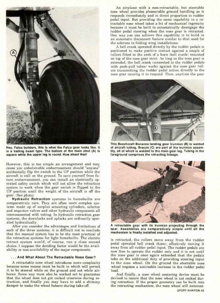
Of interest in this photo are the gear door linkage and thesimple clamping method for the brake line.
Actually, the photo is ot a waco Meteor, but the gear is al-most identical to that of the Falco. This view of the mainstrut (A) shows the squared bottom of the strut and landinggear door details.
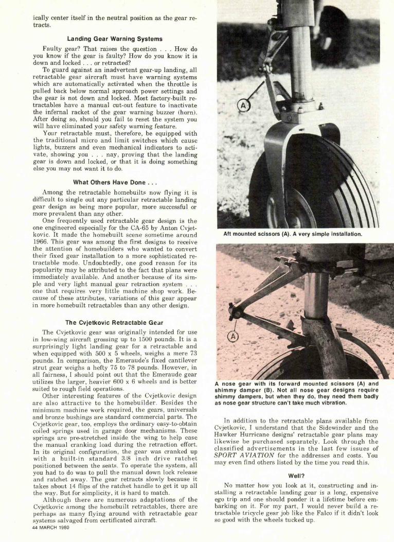
The Falco gear is electric, and to prevent accidental gear re-traction on the ground, the micro switch (B), mounted on thegear leg (C) prevents the circuit from operating until aftertake-off when the aircraft's weight is removed from theshock strut. Note the routing of the brake hose (D).
down to provide the brute force necessary to do the job.In addition, the installation requires additional gearscomprising a jack shaft arrangement to convert themotor's rotary motion into the push-pull action requiredto retract the gear.
The gear retraction switch is installed so that whenit is in the UP position, the geared motor hums into ac-tion, causing the gear to rise to its fully retracted andUP-locked position. When the gear switch is flippedDOWN, the UP-lock is released, the motor reverses andthe gear is extended to a fully down and locked position.
Hey, Falco builders, this is what the Falco gear looks like. Itis a trailing beam type. The bottom of the main strut (A) issquare while the upper leg is round. How about that!
However, this is too simple an arrangement and maycause you unbelievable embarrassment should "anyone"accidentally flip the switch to the UP position while theaircraft is still on the ground. To save yourself from fu-ture embarrassment, you can install an electrically op-erated safety switch which will not allow the retractionsystem to work when the gear switch is flipped to theUP position until the weight of the aircraft is off thegear. (See photo)
Hydraulic Retraction systems in homebuilts arecomparatively rare. They are often more complex sys-tems made up of surplus actuating cylinders, selectorand sequence valves and other hydraulic components allinterconnected with tubing. In hydraulic retraction gearsystems, the downlocks and uplocks are ordinarily oper-ated hydraulically.
After you consider the advantages and limitations ofeach of the three systems, it is difficult not to concludethat the manual system has to be the most practical ofthe retraction systems for light homebuilts. The electricretract system would, of course, run a close secondchoice. I suppose the deciding factor would be the avail-ability or non-availability of the major components.
. . . And What About The Retractable Nose Gear?A retractable nose wheel introduces more complexity
because some means must be built in which will permitit to be steered while on the ground and not while air-borne. Some way must also be worked out to guaranteethat the wheel does not get cocked crosswise during re-traction, and finally you may have to add a shimmydamper to make the wheel behave during take-off.
An airplane with a non-retractable, but steerablenose wheel provides pleasurable ground handling as itresponds immediately and in direct proportion to rudderpedal input. But providing the same capability in a re-tractable nose wheel takes a bit of mechanical ingenuitybecause it must be built to automatically disengage therudder pedal steering when the nose gear is retracted.One way you can achieve this capability is to build inan automatic disconnect feature similar to that used forthe ailerons in folding wing installations.
A bell crank operated directly by the rudder pedals ispositioned to make positive contact against a couple ofrollers fitted to the ends of a horn (bell crank) mountedon top of the nose gear strut. As long as the nose gear isextended, the bell crank (connected to the rudder pedalswith push-pull tubes) works against the nose gear roll-ers transmitting the rudder pedal action directly to thenose gear causing it to respond. Then, anytime the gear
•XThis Beechcraft Bonanza landing gear trunnion (B) is weldedof aircraft tubing. Braces (C) are part of the trunnion assem-bly, all of which is welded to the main gear leg. Tubing in theforeground comprises the retracting linkage.
A retractable gear with its trunnion projecting through thespar. Assemblies are comparatively simple until all themechanism is finally installed and adjusted.
is retracted, the rollers move away from the rudderpedal operated bell crank (horn), effectively moving itaway from all rudder pedal input. The rudder pedals arenow free to operate the rudder only and it is not untilthe nose gear is once again extended that the pedalstake on the additional duty of providing steering inputto the nose wheel. On the ground the steerable nosewheel imposes a noticeable increase in the rudder pedalload.
And finally, a nose wheel centering device must bedevised to insure that the nose wheel is not cocked dur-ing retraction. If the proper geometry can be built intothe retracting mechanism, the nose wheel will automat-
SPORT AVIATION 43
ically center itself in the neutral position as the gear re-tracts.
Landing Gear Warning SystemsFaulty gear? That raises the question . . . How do
you know if the gear is faulty? How do you know it isdown and locked . . . or retracted?
To guard against an inadvertent gear-up landing, allretractable gear aircraft must have warning systemswhich are automatically activated when the throttle ispulled back below normal approach power settings andthe gear is not down and locked. Most factory-built re-tractables have a manual cut-out feature to inactivatethe infernal racket of the gear warning buzzer (horn).After doing so, should you fail to reset the system youwill have eliminated your safety warning feature.
Your retractable must, therefore, be equipped withthe traditional micro and limit switches which causelights, buzzers and even mechanical indicators to acti-vate, showing you . . . nay, proving that the landinggear is down and locked, or that it is doing somethingelse you may not want it to do.
What Others Have Done . . .Among the retractable homebuilts now flying it is
difficult to single out any particular retractable landinggear design as being more popular, more successful ormore prevalent than any other.
One frequently used retractable gear design is theone engineered especially for the CA-65 by Anton Cvjet-kovic. It made the homebuilt scene sometime around1966. This gear was among the first designs to receivethe attention of homebuilders who wanted to converttheir fixed gear installation to a more sophisticated re-tractable mode. Undoubtedly, one good reason for itspopularity may be attributed to the fact that plans wereimmediately available. And another because of its sim-ple and very light manual gear retraction system . . .one that requires very little machine shop work. Be-cause of these attributes, variations of this gear appearin more homebuilt retractables than any other design.
The Cvjetkovic Retractable GearThe Cvjetkovic gear was originally intended for use
in low-wing aircraft grossing up to 1500 pounds. It is asurprisingly light landing gear for a retractable andwhen equipped with 500 x 5 wheels, weighs a mere 73pounds. In comparison, the Emeraude's fixed cantileverstrut gear weighs a hefty 75 to 78 pounds. However, inall fairness, I should point out that the Emeraude gearutilizes the larger, heavier 600 x 6 wheels and is bettersuited to rough field operations.
Other interesting features of the Cvjetkovic designare also attractive to the homebuilder. Besides theminimum machine work required, the gears, universalsand bronze bushings are standard commercial parts. TheCvjetkovic gear, too, employs the ordinary easy-to-obtaincoiled springs used in garage door mechanisms. Thesesprings are pre-stretched inside the wing to help easethe manual cranking load during the retraction effort.In its original configuration, the gear was cranked upwith a bu i l t - in standard 3/8 inch dr ive ratchetpositioned between the seats. To operate the system, allyou had to do was to pull the manual down lock releaseand ratchet away. The gear retracts slowly because ittakes about 14 flips of the ratchet handle to get it up allthe way. But for simplicity, it is hard to match.
Although there are numerous adaptations of theCvjetkovic among the homebuilt retractables, there areperhaps as many flying around with retractable gearsystems salvaged from certificated aircraft.44 MARCH 1980
Aft mounted scissors (A). A very simple installation.
A nose gear with its forward mounted scissors (A) andshimmy damper (B). Not all nose gear designs requireshimmy dampers, but when they do, they need them badlyas nose gear structure can't take much vibration.
In addition to the retractable plans available fromCvjetkovic, I understand that the Sidewinder and theHawker Hurricane designs' retractable gear plans maylikewise be purchased separately. Look through theclassified advertisements in the last few issues ofSPORT AVIATION for the addresses and costs. Youmay even find others listed by the time you read this.
Well?No matter how you look at it, constructing and in-
stalling a retractable landing gear is a long, expensiveego trip and one should ponder it a lifetime before em-barking on it. For my part, I would never build a re-tractable tricycle gear job like the Falco if it didn't lookso good with the wheels tucked up.