the sinuous antenna a dual polarized element for wideband ... · the sinuous antenna a dual...
TRANSCRIPT
NATIONAL RADIO ASTRONOMY OBSERVATORYGreen Bank, West Virginia
ELECTRONICS DIVISION INTERNAL REPORTNO. 301
THE SINUOUS ANTENNA A DUAL POLARIZEDELEMENT FOR WIDEBAND PHASED ARRAY FEED
APPLICATION
K. S. SainiR. F. Bradley
February 13, 1996

The Sinuous Antenna A dual polarized
element for wideband phased array feedapplication
Kamaljeet Singh Saini Richard F. Bradley
February 13, 1996
1 IntroductionTypical radioastronomy applications require wideband antenna elements to pro-vide large observable radio spectrum without the need to change feeds. Polar-ization measurements require the antenna to possess the capability of distin-guishing between two orthogonal senses of polarization(preferably linear.) in thereceived signal. Some other conventional applications, like the direction findingsystems, require similar antennas. The sinuous l antenna element described hereis one such element, suited to these kinds of applications. It is compact, hasa good E- and H- plane radiation pattern congruence, and possesses an inputimpedance which is essentially independent of frequency. Also, its phase centershows little variation over the designed band of operation. Few other candidateelements possess all these properties satisfying the requirements for similar andrelated applications.
As will be described later, the circumferential nature of current distribution,arising out of the physical geometrical shape of the element. ensures a good E-and H- plane pattern uniformity, while the self complimentary two-dimensionalstructure guarantees a frequency independent input impedance. This is impor-tant in achieving an efficient power transfer to free space over the entire bandof operation.
The sinuous element described here was designed for the 1.0GHz - 2.5GHzfrequency band. Simulated and experimental results of the antenna performanceare presented.
1 First conceived by R. H. Du Hamel, "Dual Polarized Sinuous Antennas." European PatentApplication 019 8578, filed Feb. 19, 1986. (U.S. Patent 703,042, Feb. 19, 1985.)
1
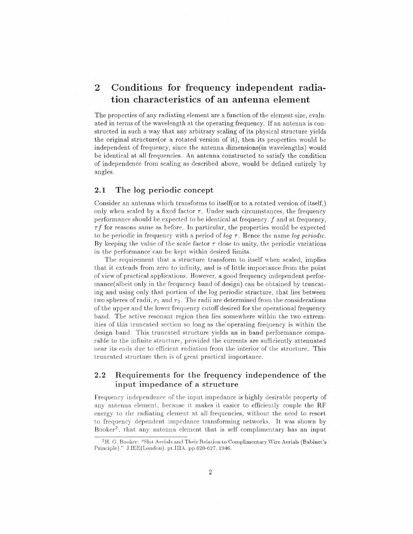
Conditions for frequency independent radia-tion characteristics of an antenna element
The properties of any radiating element are a function of the element size, evalu-ated in terms of the wavelength at the operating frequency. If an antenna is con-structed in such a way that any arbitrary scaling of its physical structure yieldsthe original structure(or a rotated version of it), then its properties would beindependent of frequency, since the antenna dimensions(in wavelengths) wouldbe identical at all frequencies. An antenna constructed to satisfy the conditionof independence from scaling as described above, would be defined entirely byangles.
2.1 The log periodic concept
Consider an antenna which transforms to itself(or to a rotated version of itself,)only when scaled by a fixed factor T. Under such circumstances, the frequencyperformance should be expected to be identical at frequency. f and at frequency,Tf for reasons same as before. In particular, the properties would be expectedto be periodic in frequency with a period of log T. Hence the name log periodic.
By keeping the value of the scale factor T close to unity, the periodic variationsin the performance can be kept within desired limits.
The requirement that a structure transform to itself when scaled, impliesthat it extends from zero to infinity, and is of little importance from the pointof view of practical applications. However, a good frequency independent perfor-mance(albeit only in the frequency band of design) can be obtained by truncat-ing and using only that portion of the log periodic structure, that lies betweentwo spheres of radii, r i and To. The radii are determined from the considerationsof the upper and the lower frequency cutoff desired for the operational frequencyband. The active resonant region then lies somewhere within the two extrem-ities of this truncated section so long as the : operating frequency is within thedesign band. This truncated structure yields an in band performance compa-rable to the infinite structure, provided the currents are sufficiently attenuatednear its ends due to efficient radiation from the interior of the structure. Thistruncated structure then is of great practical importance.
2.2 Requirements for the frequency independence of theinput impedance of a structure
Frequency independence of the input impedance is highly desirable property ofany antenna element, because it makes it easier to efficiently couple the RFenergy to the radiating element at all frequencies, without the need to resortto frequency dependent impedance transforming networks. It was shown byBooker' , that any antenna element that is self complimentary has an input
H . G. Booker: "Slot. Aerials and Their Relation to Complimentary Wire Aerials (Babinet'sPrinciple)." JJEE(London), pt.IIIA. pp.620-627, 1946.
2

impedance, which is not a function of frequency. A self complimentary struc-ture does not guarantee a frequency independent radiation pattern, but if alog periodic antenna is constructed to be self complimentary, then the elementwill exhibit a periodic variation in the radiation characteristics, while havinga constant input impedance. As stated earlier the periodic variation of theradiation characteristics could be made small by assigning to r(the log periodicscale factor,) a value close to unity. Such a structure would have a frequencyindependent radiation pattern and input impedance. This is the underlyingdesign philosophy followed to design the sinuous element.
3 Design, fabrication and assembly of the shm-ous antenna
The requirement of dual polarization dictates the need to have two equivalentstructures, each catering to one sense of polarization. This is done by firstgenerating one set of "arms" to achieve a linear polarization, and then addinganother set of arms, similar to the first one. but rotated through 90 0 , to providethe orthogonal polarization sense. It has to be ensured that the two sets of"arms" do not intersect each other, and the geometry of the structure confirmsto the log periodic principles, and is self complimentary as well. We began bytracing out the sinuous curve.
3.1 Generating the sinuous curve
The log periodic structure is considered to be composed of "cells", with each cellbeing a scaled version of its predecessor. The -cells - of the sinuous structurewere generated from the sinuous curve, which is defined by the equation providedby R. H. Du Hamel et. al.'
= (-1)P ap sin
180 ln(r/Rp)
ln(Tp)
where, 7, cb are the polar coordinates of the curve. for the p-th cell. Cell-icorresponds to the outermost cell, with radius R 1 . Therefore, Rp+ i < < R.
In general, Rp = 72, 1 To adhere to the log periodic design philosophy,
op and 7-p are constants. The sinuous curve obtained from this equation formedthe basis for creating the sinuous "arm" (see figure la) as described below.
3.2 Creating the sinuous pattern
The sinuous curve obtained above was swept through an angle + 6 about itsaxis to generate one sinuous arm(see figure lb.) This arm was then copied after
3 The design equations of the sinuous antenna are laid out in detail in the Antenna En-gineering Handbook (III Ed.), Chapter 14, Frequency Independent Antennas by R. H. DuHamel and J. P. Scherer, edited by Richard C. Johnson. Mc Craw Hill Publishers.
(1)
3

COVPLETED FOUR ARM FINAL ANTENNA REAL ZATION1 PATTERN PATTER
SINUOUS CURVE ONE "ARM FORMED BY SWEEPINGTHE SINUOUS CURVE T-ROUGH ±22.5*
HATCHED AREACUT AWAY
2. 5''
2. 5"
Figure-1

rotation through 180' about the origin. This created one dipole. This structurewas now copied after rotation through 90
0 about the origin, to get the desired
dual dipole(and hence dual polarization) sinuous antenna.This procedure was executed with the aid of Autocad. An Autolisp program
(Appendix A) was written to compute and draw the sinuous curve based on theabove equations and rules, given the design parameters: T, R 1 and the inner pat-tern radius. The basic curve, thus obtained, was subsequently manipulated asalready described to create the required artwork for printed circuit board(PCB)fabrication (see figure lc d.)
3.3 The self complimentary sinuous pattern and calcula-tion of the input impedance
A sinuous structure was generated as outlined above with the following designparameters: a = 45°, R 1 = 2.5 inches and T = 0.75. A self complimentarystructure was ensured by setting 6 = 22.5'. Figure lc d show the completedpattern with these design parameters. Notice that the actual artwork generatedhas the -stubs" occurring at the outer periphery(corresponding to the nextlarger cell of the sinuous pattern,) trimmed off. This was done because theseappendages, being of a resonant wavelength at about 1.5GHz, disturbed theradiation from the actual resonant cell at this frequency, and caused a distortionin the beam pattern shape.
As shown by Booker, an N-arm, self complimentary structure has a balancedinput impedance of each arm pair given by:
607r c?sin A17
where Al is the mode number. When fed in mode-1, a four arm structurewill therefore present an input impedance of 267Q. The actual impedance issomewhat lower owing to the feed structure at the center.
3.4 Construction and assembly
The sinuous element, as defined by the artwork, was fabricated on a 10mil thickpolyester substrate. A small hole was cut out at the center, to pass the antennafeed terminals to the balun behind. This antenna PCB disc was next attached toa 1" thick styrofoam disc of equal diameter. The styrofoam disc had a threadedteflon insert attached into the other face to hold the hollow cylindrical G-10glass epoxy rod. The balun passed through the support rod and styrofoam disc,and through the hole in the center of the antenna PCB, connected to the feedterminals. The whole assembly was itself fixed to a reflecting backplane by thesupport rod with the aid of a mounting ring assembly.
Zm (2)
5

3.5 Frequency coverage
For a sinuous structure, the active resonant region lies at a radius given by
r = 4( + (3)
where, a and 5 are in radians. The resonant radii at various frequencies for thechosen design parameters are tabulated below, based on the above relation.
Freq.(GH ) Resonant Radius(inch)
1.0 2.51.2 2.11.4 1.81.6 1.61.8 1.42.0 1.22.5 1.1
Thus the 5 inch diameter element designed above, covers the entire 1.0GHz- 2.5GHz band as desired.
4 The feed structureTo match the 50Q unbalanced source to the balanced impedance presented bythe element, a "tapered stripline" balun was used. A Klopfenstein 4 impedancetaper profile was used, and the ground plane was tapered simultaneously toprovide the required transition from a balanced line to an unbalanced line. Thebalun used was designed to transform a 1402 balanced impedance to a 502unbalanced impedance. The use of a 1409. balun with an antenna that presentsabout 240Q impedance, was resulted in sotne impedance mismatch. and anexpected standing wave ratio(SWR) of about 1.7 .
4.1 Balun designThe Klopfenstein impedance taper is defined by:
1/7-2 Z(z) = —
2 177(Z,ZL ) +
F,cosh A
A 2 0(2zIL — 1, A)
where 0 < < L and I' m = F o lcosh A. F„, being the maximum permissiblereflection coefficient in the passband of the taper, and F, = Themodified Bessel function o(x. A) was computed using the technique providedby Grossberg 5 . The required impedance profile to match 140Q to 50Q was
4 R. W. Klopfenstein,"A Transmission Line Taper of Improved Design," Proc. IRE. Vol.44,pp.31-15, January 1956.
5 1\4. A. Grossberg,"Extremely Rapid computation of the Klopfenstein Impedance Taper",Proc. IEEE, Vol.56, pp.1629-1630, September 1968.
(4)
6

subsequently computed. The trackwidth profile was subsequently computednumerically, using the HP-High Frequency Structure Simulator (HESS) softwarefor a 62mi1 FR-4 Glass Epoxy substrate, ( 7, = 4.8 (Appendix B.)
The balun was fabricated after preparing an artwork based on the the abovecalculations. An SMA connector soldered to the 50Q end, formed the test andmeasurement port.
Subsequently, a better match was obtained by redesigning the balun onsimilar lines for 240Q impedance using a 125mi1 FR-4 Glass Epoxy substrate,E l . = 4.8 (Appendix B.) This balun was not available at the time of the exper-iment, and so all the subsequent antenna measurements were made using the140Q balun constructed as described above.
4.2 Balun performance
To check the performance of the balun, the balanced end was terminated witha 140Q chip resistor, and return loss was measured at the 509. port, using avector network analyzer. The return loss was found to be better than -20dB in1.0GHz to 2.0G-Hz frequency band.
The modified balun had a return loss of better than -18dB in the samefrequency range, when terminated with a 2402 resistive network.
5 Element performanceThis section presents the simulated as well as experimental performance resultsof one sinuous antenna element mounted in front of a reflecting backplane(toget a unidirectional beam), and fed by a tapered stripline balun as constructedabove.
5.1 HFSS simulation
The antenna element consisting of the sinuous structure and the tapered balunwere entered into the HFSS 6 to get an estimate of the expected radiation pat-tern. Owing to computing constraints, the structure consisted of only one pairof arms corresponding to one sense of polarization, instead of the usual two.This deprived the property of self complimentary symmetry from the structureand could lead to a non constant value for the input impedance. and some vari-ation of beam shape in the simulated results. The sinuous pattern was modeledusing 100mil long line segments, instead of the finer resolution used in generat-ing the artwork for actual PCB fabrication, to reduce the mesh complexity. The"arms" were fed by equally excited coaxial lines, whose lengths were differentby 180' at 1.0GHz, to simulate balanced excitation of the antenna structure.The radiation pattern plot at 1.0GHz is shown in figure 2. The 3dB beamwidthturns out to be about 80°.
6 HP's High Frequency Structure Simulator, Release 3.10 was used to carry out thesimulations.
7

x Y
Mag. E—field (dB) vs. Theta (degrees), at 1000 MHz0
- 2
- 3 -
-4
CD-5
- -
- 7 -
-8 -Z1 ..-
- 9
- 10-MILLI!! 1 1 1 , 1 1 1 1 l ,_111,1t11.1 1 1 , 1 1 , 1 t 1 1 1 1 1 , 1 1 1 1
0 11.25 22.5 33.75 45 56.25 67.5 78.75 90
Theta (degrees)
ec.6.uma

5.2 Experimental results
5.2.1 Radiation pattern
Measurements were carried out by using the sinuous test antenna as the receiveelement on the test range 7 . The transmit antenna was an L-band horn(designband of 1.3GHz - 1.7GHz), fed by a CW carrier from a signal generator. Thereceived signal from the test antenna was compared against a sample of thetransmitted signal using a phase-amplitude measurement system. The receiveantenna was rotated in azimuth, and the received signal strength was recordedas a function of the azimuthal position to yield the required radiation patternfor the test antenna. Care was taken to ensure that the axis of rotation of thetest antenna coincided with its phase center, to avoid filling up nulls in thebeam pattern, if any. This adjustment required the test antenna to be movedalong the radial axis towards(or away from) the transmitting horn, till the phasevariation -was contained within ±4' for azimuthal positions ranging from —45'to +45°. Measurements were made by rotating the test antenna both in itsE-plane and H-plane, at 1.0, 1.2, 1.4, 1.6, 1.8 and 2.0GHz. The :3dB beamwidthwas 80°, in close agreement with the predicted value. (See figure 3.)
5.2.2 Polarization wobble and cross-polarization rejection
The polarization wobble was measured by turning the polarization of the trans-mit horn, and locating its orientation for the sharply defined minima in thereceived signal strength as a function of frequency in the 1.0GHz - 2GHz band.The polarization wobble was +5° in this frequency range. The cross-polarizationrejection was better than -25dB throughout the band. See figure 4.)
5.2.3 SWR measurements
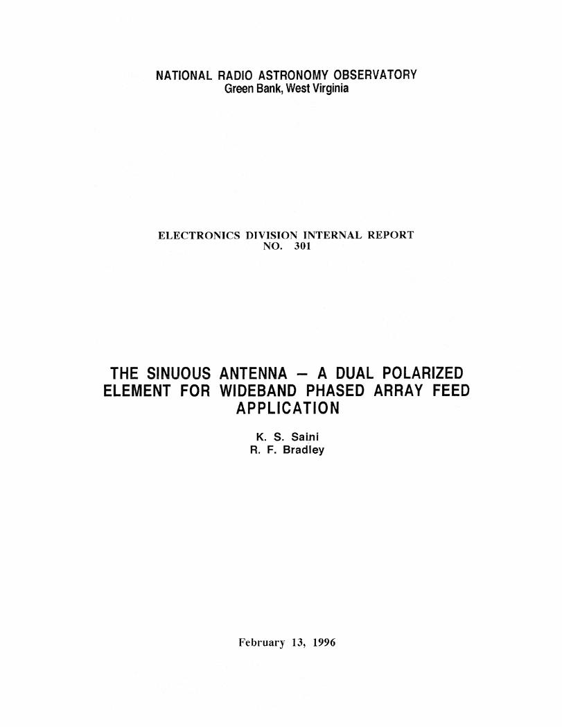
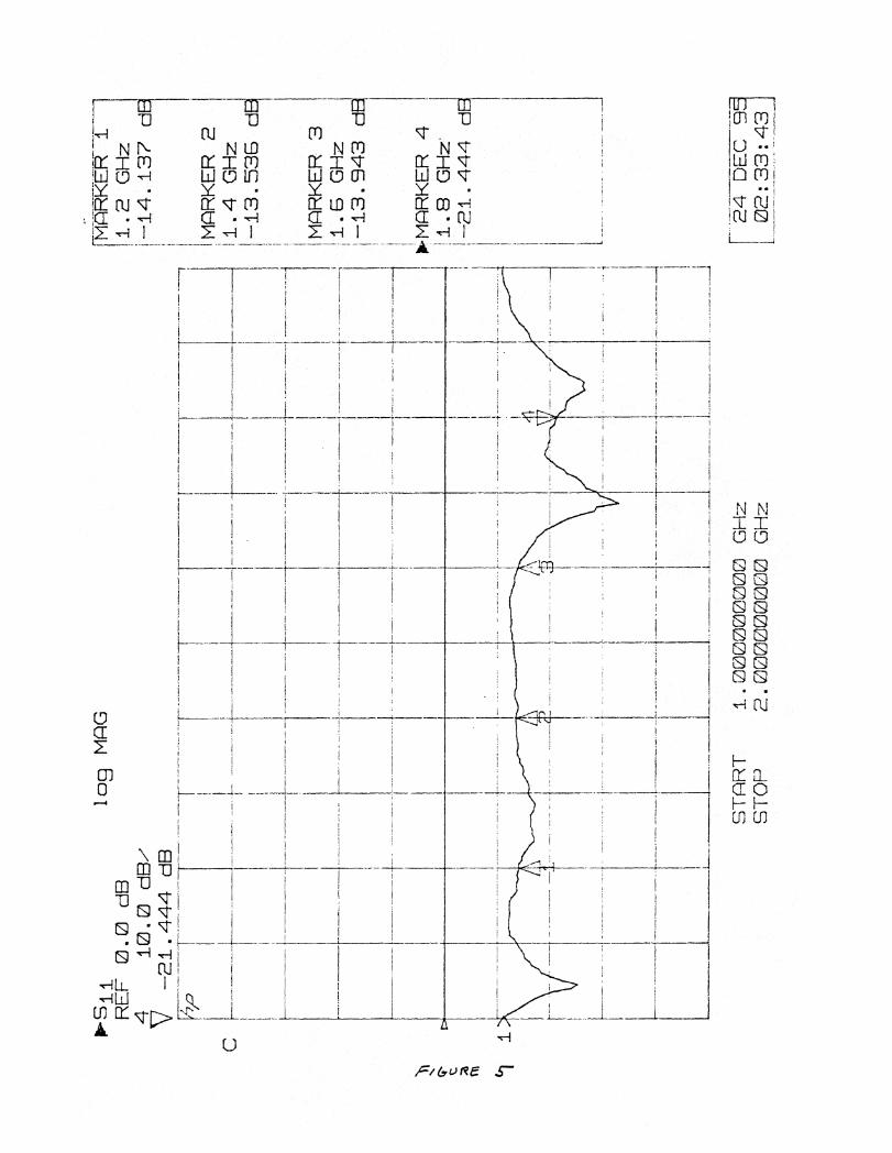
SWR measurements were made using a vector network analyzer, connected atthe input of the balun, in a single port configuration. The measured SIVE.was about 1.5 without the metallic backplane, and in the range of 1.8 - 2.0with it close to the theoretically expected value of 1.7 for the balun used.The placement of the backplane introduced a reactive component in the inputimpedance. (See figure 5.)
6 Conclusion
Antennas are impedance matching devices. that transform the impedance ofthe RF source to that of free space. To be useful, they should be capableof achieving this transformation over the entire band of operation(frequencyindependent input impedance.) A high bandwidth system therefore requiresa wideband antenna. Additionally, the radiation pattern should be same at
7 Measurements were carried out at the antenna test facility of the National Radio Astron-omy Observatory, Green Bank, West Virginia.
9

50 100 -100 100-100 -50 0Azimuth (degrees)
50-50 0Aztr- -th (degrees)
1.8 GHz 2.3 GHz
1.4 GHz .6 GHz
-5
-10
-15
-20
-25
-30
-10
-1
-15
-20
-25
-30
-50 0 50Azimuth (degrees)
-35
-35-40 ^
-45 -40-100 100100 50-100 -50 0
Azim_ ,.h (degrees)
^
-10
-15
-20
-25
-30
-35
-40
45
t_
^
1
%,11
-a
-10
-15
-20
-25
-30
-35
-40
-45
-50
-
-
-
711
t-
-5
-10
-15
-20
-25
-30
-35
1.0 GHz
-5
-10
-15
-20
-25
-30
-35
-40
-45
-50
1.2 GHz
-40
1
1
X
I
,
.." "
•
'
I
^
-100 -50 0 50 100 -100 -50 0 50 100Azimuth (degrees) (degrees)
Figure-3
10

Cross polarization measurements
1.2 1.4 1.6Frequency (GHz)
Polarization wobble
1.2 1.4 1.6 1.8 2Frequency (GHz)
Figure-4
11
MAR
KER
2. G
Hz
13.5
3B d
9
MAR
KER
3. G
GH
z-1
3.9
43 d
01 -MAR
KER
41.
9 G
Hz
-21.4
44 d
STAR
Ti C
i100
0000
C/J1
GHz
STO
P2.
0000
0000
0 G
Hz
22 17- 15
EC (3
1L
02:3
3:43
109
MPG
REF
0.0
dB
,410.0
dB,
V -
2i 444 d
B
(---N 4R1
..<1E
R i J
1 . 2
GHz
-14 i37 d
F—
-

all frequencies in the operation band. Further, some applications require theantenna to be polarized, while some require that the physical structure be assmall as possible. The ease of fabrication of the structure, should be viewed asan added advantage.
The sinuous antenna described above. has all these qualities, and should beparticularly useful for phased focal plane array applications.
7 AcknowledgementsWe would like to thank Dr.J. R. Fisher who made many suggestions to improvethe performance of the antenna. Most of his suggestions were incorporated intoour final design.
We also acknowledge the contributions of Donald G. Stone who preparedAutocad drawings and artworks for our designs, of Richard Hall and Danny E.Boyd who helped us in assembly and testing of the numerous prototypes of ourantenna elements, and of Garnet Taylor who fabricated most of the structuralcomponents for the assembly and mounting arrangement of the antenna.
13

Appendix: A
• Listing of the Autolisp routine.

,5
;;Autolisp routine to generate the basic sinuous curve, given the;;parameters:,,minimum radius -> radius of the inner circle that truncates the;;infinite pattern at the high frequency end.;;maximum radius -> radius of the outer circle that truncates the;;infinite pattern at the low frequency end.;;tau -> the log periodic cell scale factor.;;incremental step -> the lengths of straight line segments used;;to implement the curve.••,5
;;Donald G. Stone
(defun curve 0(prompt "Routine to draw the basic sinuous curve ") (terpri)(setq start (getpoint "Pick the start point ")) (terpri)(setq rl (getreal "Enter the minimum radius ")) (terpri)(setq r2 (getreal "Enter the maximum radius ")) (terpri)(setq s (getreal "Enter the incremental step ")) (terpri)(setq tau (getreal "Enter the value of tau ")) (terpri)
(while (< rl (- r2 s))(setq fl (* (/ pi 4) (sin (* pi (/ (log (/ rl r2)) (log tau))))))(setq x 1 (+ (* rl (cos fl)) (car start)))(setq yl (+ (* rl (sin fl)) (cadr start)))(setq rl (+ rl s))(setq f2 (* (/ pi 4) (sin (* pi (/ (log (I r 1 r2)) (log tau))))))(setq x2 (+ (* rl (cos f2)) (car start)))(setq y2 (+ (* rl (sin f2)) (cadr start)))(command "line"
(setq p (list xl y1))(setq p (list x2 y2))

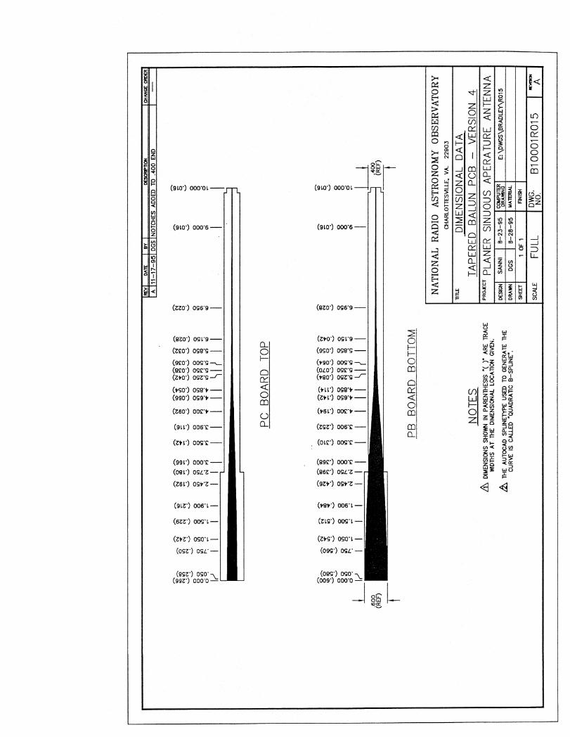
Appendix: B
*Mechanical details of the 50Q - 140Q balun (Version 2.)
(The drawing shows two baluns drawn back to back.This was done for the convenience of fabrication.)
Mechanical details of the 50Q - 240Q balun (Version 4.)
• Performance plot of the 50C2 - 240C2 balun.

1111
ED
IME
NS
ION
AL
DA
TA
N
Arn
mE
NN
OM
ON
■111
1111
1111
1111
1111
111
■-■
er)
1-■ u
l Pr
) Cs -
'F.-
4-
n o 0P-
42
8̀1 . 0
."
c cl
o" 5
.
hco
in 0,
1 co
inM
I M
I 0,1
C• I
v-
.—Z
C
s .")
. co.
co)
11111111
11■■
In r 2.
§( 1
qcv
in c
o ,-
hc( c1
(134 .
P!
Pe) .
;
1111
1111
111
0,1
0 0 0 ••
••:,
I A 0
3
71: I
I
PC
BO
AR
D T
OP
r 's
O15.
43
8(.1
.4),A
i cq
agi
A (
T, , ,5
3 54!
8 5
301
,...,.-00000000003 55
60`8
1000
0000
8,...
,_cv
PC
BO
AR
D B
OT
TO
M
NO
TE
S D
IMEN
SIO
NS
IN P
AREN
TH
ESIS
"0"
ARE
FRO
M T
HE
CEN
TER
UN
E O
F TH
E ARTW
ORK.
EACH
HALF
OF
TH
E VER
TIC
AL
DIM
ENSI
ON
S O
RIG
INATE
FRO
M T
HEI
R R
ESPE
CTI
VE
OU
TSID
E EN
D.
A TH
E A
UTO
CA
D S
PLIN
ETt'P
E U
SED
TO
GEN
ERA
TE T
HE
CU
RV
E IS
CA
LLED
"Q
UA
DR
ATI
C B
—SP
UN
E".
FIN
ISH
NA
TIO
NA
L R
AD
IO A
ST
RO
NO
MY
OB
SE
RV
AT
OR
YC
HA
RL
OT
TE
SVIL
LE
, VA
. 229
03
TA
PE
RE
D B
AL
UN
PC
B -
VE
RS
ION
2
PR
OJE
CT
SIN
UO
US
AP
ER
AT
UR
E A
NT
EN
NA
DE
SIG
NR.
BRA
DLE
Y3
-28
-94
CO
MPU
TE
RD
RA
WIN
GD
: \D
WG
S\B
RA
DL
EY
\R00
2
DR
AW
ND
GS
3-1
2-9
4
DW
G.
NO
. B
1 0
001 R
002
SHE
ET
1 O
F 1
SCA
LEFU
LL
MA
TER
IAL
TAPE
RED
SEC
TIO
NTA
PERED
SEC
TIO
N
F,r cy
iTcg
Fro ;§
Z-1 1= 4) '71
c4 (
4Ki 4 . 4,
4. 4
. 4, -4:
-4*-
4 1
4 KS
c•I c
•I
111
11
11
11
11
11
??1
1111
1111
1111
TAPE
RED
SEC
TIO
N
9.60
0
0
I
.400
(REF
)
Li
ITA
PERED
SEC
TIO
N
PB
BO
ARD
BO
TTO
M
1 .4
00
(RE
F)
RE
VD
AT
EB
YD
ES
CR
P1
ION
CH
AN
GE
OR
DE
R
A 11
-17-
95 D
GS
NO
TCH
ES A
DD
ED T
O .40
0 EN
D
e•-
■..
...
,..,
toCCill
:LiN
(0.4-
.-N
v-.--
.........
3 3
3....
.......
..N
.--
o 00 o o
cc?)1
10 i
on 0
o o
tr)
I('I
II
II
II
II
CO
N 0
3 (
0 N
coI')
if) 1
4 1rr)
00 000 0
§CO
000 0
In 1
0 0
inN
1'1
In 0
3 0
10 uti
I I
( 11I
I
...,
e-,
/....
LO
.--
.t O
CO
0N .4
-(7
)
N I
n.-
: 04
o 00
0 i
n °.
,0 "N ...
.-:,
o
N ....> §
•ri
0
PC B
OARD
TO
P
NA
TIO
NA
L R
AD
IOR
AD
IO A
ST
RO
NO
MY
OB
SE
RV
AT
OR
YCH
ARLO
TTES
VILL
E, V
A. 2
2903
NO
TES.
TIT
LED
IMEN
SIO
NAL
DATA
TAPERED
BALU
N P
CB —
VERSIO
N 4
4&
D
IME
NS
ION
S S
HO
WN
IN
PAR
ENTH
ESIS
"(
)AR
E T
RA
CE
WID
TH
S A
T T
HE
DIM
EN
SIO
NA
L L
OC
AT
ION
GIV
EN
.PR'
EcT
PL
AN
ER
SIN
UO
US
AP
ER
AT
UR
E A
NT
EN
NA
TH
E A
UT
OC
AD
SP
LIN
ET
YP
E U
SE
D T
O G
EN
ER
AT
E T
HE
DE
SIG
NSA
NN
I8-2
3-9
5C
OM
PU
TE
RD
RA
WIN
GE
: \D
WG
S \B
RA
D L
EY
\R01
5
CU
RV
E I
S C
AL
LE
D "
'QU
AD
RA
TIC
8-S
PL
INE
".D
RA
VA
4D
GS
8-2
8-9
5M
AT
ER
IAL
SH
EE
T1 O
F 1
FIN
ISH
DW
G.
B10
001R
015
NO
.SC
ALE
FULL

ARKE
R.!i
a GH
z-i
7.5
39 d
B
MARKER
21.4
GH
z-3
i.495 d
MARKER
'31.6
GH
2-2
9.4
64 d
,MARKER
41.8
GH
z-i
9.1
02 d
B
PPSii
REF 0
.0 d
B10.0
dB/
-i9.1
_02 d
B
109
MPG
SO
— 4
0 _
A, Z
A L
oos)
STPR
T 1.0
00000000 G
Hz
STO
P2.0
00000000 G
Hz
24 D
EC 9
5I
01:3
3:i
4
11 P