the simulation of indoor service range prediction of ...ijetch.org/papers/527-r3009.pdf · antennas...
TRANSCRIPT

Abstract—Wireless Radio Access Point (RAP) For Radio
Over Fiber (ROF) System is becoming an increasingly
important technology for the indoor wireless market. The
dynamic range requirements and optimum choice of laser are
identified for this application. A novel architecture based on the
radio over fiber application is proposed for indoor application,
which gives important benefits in terms of design, installation
and operation of the systems used. To meet increasing of user
bandwidth and wireless demands, the Wireless design based on
ROF technology has been proposed as a promising cost effective
solution. In this network, a central station (CS) is connected to
numerous RAP using an optical fiber to indoor connection. The
aim of this project is to predict the service range for RAP for
downlink transmission. The indoor RF front end consists of a
photodiode, bandpass filter (BPF), power amplifier (PA) and an
antenna which operating at 2.4GHz band. BPF is needed to
remove out the frequency from nonlinear effect of fiber and
pass through the signal at the operating frequency. The RF
front end components are modelled using S-Parameter
measured data from factory. Indoor picocells are used power
lower than 1 Watt (30 dBm) and service range of more than 100
meters.
Index Terms—Radio over fiber, radio access point,
optisystem.
I. INTRODUCTION
A key enabler for supporting very high data rates in
advanced networks is the reduction in cell size, which serves
two main purposes which are maintained the high SNR at the
receiver while limiting the transmit power to moderate levels
and limiting the number of users per cell [1][2]. Unlike wired
networks with dedicated connections to the user, a wireless
network consists of a shared bandwidth and cells with
multiple users. One solution to increasing the data rate is
through the use of a larger bandwidth and developing special
diversity antenna systems in a
multiple-input–multiple-output (MIMO) configuration [3].
However, the most effective way to improve the throughput
per user is to reduce the number of users per cell by designing
networks with a very small cell size. For indoor applications
with very high user density, a cell may only have a radius of a
few meters. Such systems are typically called picocellular
networks. By reducing the cell size, the number of radio
interfaces in the deployment area can be very high. In some
deployment scenarios, hundreds of antennas need to be
supported. This results in significant challenges for the wired
infrastructure that is required to connect the numerous
Manuscript received October 25, 2012; revised November 26, 2012.
The authors are with the University Kuala Lumpur British Malaysian
Institute, 53100 Gombak Selangor, Malaysia (e-mail:
antennas to a central control station.
The most effective and efficient way of providing this
coverage with good service quality is to place one or more
base stations at a central location inside the building and use a
distributed antenna system (DAS) transmission infrastructure
to distribute the wireless signals from the base stations to the
various antenna locations around the building [4]. Although
DASs can be constructed using coaxial cable, the preferred
option for larger installations is optical fiber cable. This is
due to the very high attenuation of coaxial cable, which
makes longer transmission spans impractical.
II. RELATED WORK
There are several projects that focusing on indoor radio
transmission performance. However, the objective and
method used is a little bit different. The first paper is a
prediction of propagation characteristics in indoor radio
communication environments by N. Yarkoni and N.
Blaunstein, 2006 [5]. This paper presented a semi empirical
and analytical model approach to predict the total path loss in
various indoor communication channel links by taking the
effects of fading floors and corridors respectively by
estimated the slow and fast fading caused by multipath and
diffraction phenomena. This paper proposed an unified
approach of comparison with the analytical Bertoni’s model
which are common method that used to calculated the link
budget in indoor environment. The result also comparable
with the measurement carried for different propagation
method along corridor and between floors that occurs in the
indoor environments for communication channels. The
second paper is ITU field strength prediction methods for
terrestrial point to area services by Rainer Grosskopf, 2007 [6]
develops propagation prediction and recommendations
providing information methods for various communication
services on the wotk carried out in International
Telecommunication Union (ITU) radiowave propagation
study group for terrestrial point to area services such as land
mobile services and terrestrial broadcasting services. This
paper cover propagation in the Very high Frequency (VHF)
and Ultra High Frequency (UHF) range, short range indoor
and outdoor services for frequency range from 1 to 100 GHz
and from point to multipoint services the the frequency range
from 3 to 60 GHz. The third paper is a coverage prediction
and optimization algorithms for indoor environments by
David Plets et al, 2012 [7] developed about a heuristic
algorithm for prediction of indoor wireless WiFi 802.11b/g
coverage. The measurements on a single floor of an office
building are performed to investigate the propagation
characteristics. The prediction method that used based on the
free space loss model for each environment to reduce the
The Simulation of Indoor Service Range Prediction of
Wireless Radio Access Point for Radio over Fiber System
Z. Kornain, M. A. Abu, and M. Y. Yacob
136
IACSIT International Journal of Engineering and Technology, Vol. 5, No. 1, February 2013
DOI: 10.7763/IJET.2013.V5.527
dependency of the test model based on the case with many
other models. The result of the algorithm to a wireless
network is discussed based on the site experiment. This
method proposed a physically accurate prediction of the path
loss model for different building types.
III. PROPOSED TECHNIQUE
The objective of this project is to design and simulate the
radio access point (RAP) for radio over fiber system (ROF)
and to predict the range of RAP for indoor application using
Optisystem software. This project mainly focused on the
design ROF using OptiSystem. Fig. 1 shows the flow chart of
this project process, which involve literature review study,
software study, and design study.
Fig. 1. Flow chart of the project process.
By starting of this project, the study the fiber optic system
needed to make more understanding on the optical system.
With more knowledge on this technologies can help in using
the program of OptiSystem to make suitable design for
generating optical microwave frequency and using
components. Besides that, the literature study on radio
frequency (RF) component also important to apply the
knowledge on designing suitable component. The final part is
to combine the two designs to make the combination of
optical signal to propagate by antenna designed. Thus the
simulation on the performance and usability need to be
considered.
In order to predict the service range, the Keenan-Motley
indoor channel equation has been used [8].
L= S + 10n.log (d) (1.0)
L: total propagation loss (dB), S: path loss at 1m from
transmitter (dB), n: power law index, d: distance between
transmitter and receiver (m)
where n=3; S= 21 + 20 log (f/1.7) dB; f in GHz
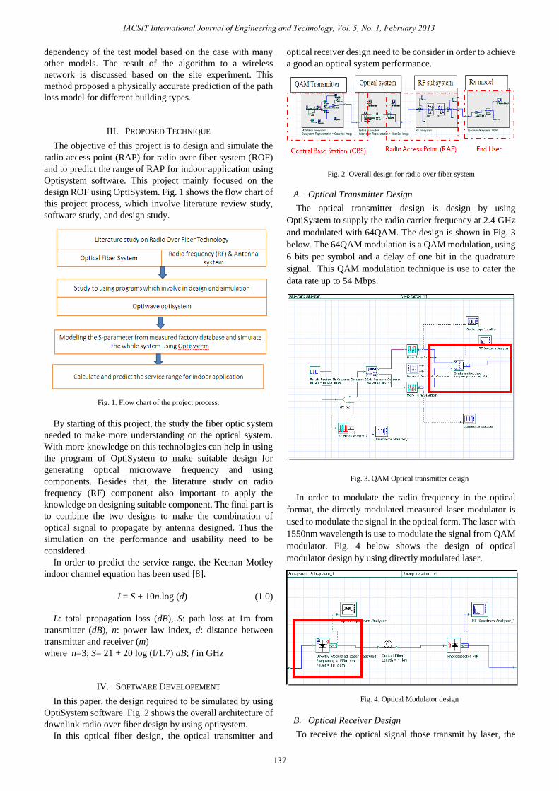
IV. SOFTWARE DEVELOPEMENT
In this paper, the design required to be simulated by using
OptiSystem software. Fig. 2 shows the overall architecture of
downlink radio over fiber design by using optisystem.
In this optical fiber design, the optical transmitter and
optical receiver design need to be consider in order to achieve
a good an optical system performance.
Fig. 2. Overall design for radio over fiber system
A. Optical Transmitter Design
The optical transmitter design is design by using
OptiSystem to supply the radio carrier frequency at 2.4 GHz
and modulated with 64QAM. The design is shown in Fig. 3
below. The 64QAM modulation is a QAM modulation, using
6 bits per symbol and a delay of one bit in the quadrature
signal. This QAM modulation technique is use to cater the
data rate up to 54 Mbps.
Fig. 3. QAM Optical transmitter design
In order to modulate the radio frequency in the optical
format, the directly modulated measured laser modulator is
used to modulate the signal in the optical form. The laser with
1550nm wavelength is use to modulate the signal from QAM
modulator. Fig. 4 below shows the design of optical
modulator design by using directly modulated laser.
Fig. 4. Optical Modulator design
B. Optical Receiver Design
To receive the optical signal those transmit by laser, the
137
IACSIT International Journal of Engineering and Technology, Vol. 5, No. 1, February 2013

optical receiver design needs to perform for this project.
Table I shows the design goal for optical receiver design.
TABLE I: OPTICAL RECEIVER SPECIFICATIONS
Optical Link
Length (KM) 0-150 KM
Fiber Loss 0.2 dB/KM
Fiber Dispersion Constant 16.75 ps/nm/km
Optical Receiver
Responsivity 1 A/W
Dark Current 10 nA
The design parameter is fetch from the literature review
that has been studied from the previous part. Fig. 5 below
show the connection between optical transmitter (laser) and
the photo detector that use to convert the optical signal into
the RF signal that will be used by the RF component.
Fig. 5. Photo detector optical receiver design
C. BPF in Optisystem.
The s-2 parameters that obtain from the microwave office
will be used in this optisystem software. The signal from
photodiode RF form will be filtered by Pre-BPF and signal
from power amplifier will be filtered by post BPF. Fig. 6
below show the design of BPF in optisystem software.
Fig. 6. BPF design in optisystem.
D. Optisystem Power Amplifier
In optisystem software, the s2p block diagram of electrical
amplifier was used to model the power amplifier. This design
needs two power amplifiers because it’s hard to find one
power amplifier that can have a gain more than 60dB. Fig. 7
shows the design of power amplifier in optisystem software.
Fig. 7. Power amplifier block in optisystem
E. Antenna Block in Optisystem
Since in the optisystem software doesn’t have antenna
block representations, the 2 port s-parameter block will be
used to model the antenna in 2 port s-parameter [8]. Fig. 8
below shows the 2-port parameter antenna model.
Fig. 8. 2-port S2-parameter antenna model
V. APPLYING PROPOSED TECHNIQUE
This section will provide a write-up on how the simulation
is carried up including all assumptions used and how
important parameters are chosen. These sections also discuss
the simulations which are relevant to show the effectiveness
or superiority of the proposed technique.
From the Keenan-Motley indoor channel equation in the
section before, the attenuation at 100 meter is 84.14dB. Fig. 9
below shows the modelling of service range prediction.
Antenna is used in received mode.
138
IACSIT International Journal of Engineering and Technology, Vol. 5, No. 1, February 2013

VI. RESULT AND DISCUSSION
Since the objective of this project is to develop and
simulate the downlink radio access point (RAP) for radio
over fiber system (RoF) and to analyze the performance of
the RAP for downlink transmission using Optisystem
software, this section will show the result of simulation and
the output result from actual measured test board .Fig. 10
below shows the output after receive antenna. The spectrum
power after receive antenna for simulation part is -58.7 dBm.
Fig. 9. Indoor Path loss model in optisystem
Fig. 10. Simulation result of service range after 100m
Fig. 11 below shows the output after receive antenna. The
spectrum power after receive antenna for measured part is
-60.8 dBm.
Fig. 11. Spectrum result with measured component after 100m
Result for attenuation at minimum sensitivity which is -65
dBm is 90.44 dB. The maximum service range for simulation
part is 162.2 meter using Keenan Motley model.
Table II below shows the link budget of simulation result
based on output result for every part such as RF modulator,
laser, photodiode, filter, amplifier, transmit antenna and
received antenna.
TABLE II: THE LINK BUDGET OF SIMULATION RESULT
VII. CONCLUSIONS
Radio over fiber (RoF) is the device that proposes to
replace the conventional Radio Frequency (RF) electronic
equipments. The conventional devices need a lot of
electronic circuit to function as switch and hub, for multiple
access application. However the proposed RoF with only
simple components integrated will able to function as well as
the processing of switch and hub did by center server. In this
project, the target point is to replace the conventional radio
access point using currently. From the design which
presented at the design chapter, the RoF is shown by
OptiSystem software which integrated with the required
components, and tested under current radio access point
system. The design of RAP was successfully simulated using
Optisystem software. The front end consists of BPF, PA and
Antenna which used for the RoF technology. Those of
components are placed after the photodiode in the RAP. The
BPF is used for remove out the band interference of operating
frequency at WLAN 2.4 GHz band. While PA can be used
for increases the power level of the signal which satisfied for
the picocell application and the antenna is used to radiate the
signal. For the maximum service range, the simulation result
gives the maximum range of 162.2 meters. However, it’s
hard to find the measured component that has a good
S-parameter result because if the manufacturing design
constrains.
REFERENCES
-58.7 dBm
-60.8 dBm
From Tx
Antenna
139
IACSIT International Journal of Engineering and Technology, Vol. 5, No. 1, February 2013
[1] A. F. Molisch, Wireless Communications. Chichester, U.K.: Wiley,
2005.
[2] A. Goldsmith, Wireless Communications. Cambridge, U.K.:
Cambridge Univ. Press, 2005.
[3] A. J. Paulraj, D. A. Gore, R. U. Nabar, and H. Boelcskei, ―An overview
of MIMO communications—A key to gigabit wireless,‖ Proc. IEEE,
vol. 92, no. 2, pp. 198-218, Feb. 2004.
[4] In-Building Wireless Systems, AB1 Research, 2004.
[5] N. Yarkoni and N. Blaunstein, ―Prediction of propagation
characteristics in indoor radio communication environments,‖
Progress In Electromagnetics Research, vol. 59, pp. 151-174, 2006.
[6] R. Grosskopf, ―ITU Field-strength prediction methods for terrestrial
point to area services,‖ in Proc. of WFMN07, pp 63-67, 2007.
140
IACSIT International Journal of Engineering and Technology, Vol. 5, No. 1, February 2013
[7] D. Plets, W. Joseph, K. Vanhecke, E. Tanghe, and L. Martens,
―Coverage prediction and optimization algorithms for indoor
environments,‖ EURASIP Journal on Wireless Communication and
Networking, pp. 1-23, 2012.
[8] B. Rodney, Microstrip Patch Antennas: A Designer's Guide,
Waterhouse, Springer, 2003.
[9] Electronics Manufactuers the Premier Industry Portal. [Online].
Available:
http://www.electronics-manufacturers.com/info/optoelectronics/pin-a
valanche-photodiode.html
[10] T. Prakoso, R. Ngah, T. A. Rahman, and M. A. Mualif, ―5.8 GHz
photonic antenna for point to point applications,‖ IEEE International
Rf and Microwave Conference Proceedings, pp. 131-134, 2008.
[11] Optisystem by Optiwave System, inc, 2008, Optiwave system inc.
[12] Serving the Radio Community Since. (1942). [Online]. Available:
http://www.universal-radio.com/catalog/cable/coaxperf.html
[13] I. Frigyes, ―Basic microwave properties of optical link,‖ in Hamed Al-
Raweshidy, Shozo Komaki. Radio over Fiber Technologies for Mobile
Communications Network: Artech House Inc., USA, 2002.
[14] T. M. Govern, ―A planar, balanced approach to increase transmitter
linearity,‖ Texas Instruments Appplication report, USA, 2005.
[15] A. J. Seeds, ―Photonic techniques for microwave frequency synthesis,‖
The 13th Annual Meeting of the Lasers and Electro-Optics Society,
LEOS 2000, vol. 1, pp. 72-73, 2000
[16] S. O. Kasap, ―Optoelectronics and photonics, principles and practices,‖
Prentice-Hall International, NJ, USA, 2001.
[17] I. Frigyes, ―Basic microwave properties of optical link,‖ in Hamed Al-
Raweshidy, Shozo Komaki. Radio over Fiber Technologies for Mobile
[18] A. J. Seeds, W. I. McMillan, C. R. Pescod, M. J. Wale, and W. S.
Birkmayer, ―Optical control of phased array antennas: A european
perspective,‖ IEEEMTT-S International Microwave Symposium Digest,
vol. 3, pp. 1343-1347, May 1990.
[19] A. J. Seeds and A. A. A. D. Salles, ―Optical control of microwave
semiconductor devices,‖ IEEE Transactions on Microwave Theory and
Techniques, vol. 38, no. 5, pp. 577-585, May 1990.