the s/eaf® continuous electric arc steelmaking...
TRANSCRIPT
MIL
LEN
NIU
M S
TEEL
201
3
42
The S/EAF® continuous electric arc steelmaking processThe new SMS Siemag S/EAF steelmaking process provides continuous steelmaking for up to a week at a time. DRI, scrap and hot metal are continuously fed with the furnace under power, providing stable and flat bath refining conditions. Benefits are higher productivity, lower capital and running costs, and improved environmental outcomes.
The electric arc furnace (EAF) is the core of an electric steelmaking plant and has a decisive impact on annual
production and energy costs. Normally, EAF operation is not continuous, but is interrupted by charging of scrap, changing the electrodes and tapping steel, but in order to shorten this expensive non-productive time, adequate technical solutions have to be available.
The ARCCESS® or steady EAF (S/EAF®) process is a new development from SMS Siemag, which allows continuous operation for up to a week, with a subsequent maintenance shift for mechanical maintenance and intermediate refractory
Authors: Thomas Germershausen and Jan BaderSMS Siemag AG
r Fig 1 Illustration of the S/EAF
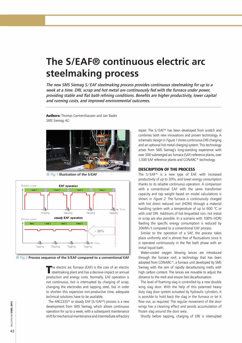
r Fig 2 Process sequence of the S/EAF compared to a conventional EAF
repair. The S/EAF® has been developed from scratch and combines both new innovations and proven technology. A schematic design in Figure 1 shows continuous DRI charging and an optional hot metal charging system. This technology arises from SMS Siemag’s long-standing experience with over 300 submerged-arc furnace (SAF) reference plants, over 1,300 EAF reference plants and CONARC® technology.
DESCRIPTION OF THE PROCESSThe S/EAF® is a new type of EAF, with increased productivity of up to 30%, and lower energy consumption thanks to its reliable continuous operation. A comparison with a conventional EAF with the same transformer capacity and tap weight based on model calculations is shown in Figure 2. The furnace is continuously charged with hot direct reduced iron (HDRI) through a material handling system with a temperature of up to 600 °C or with cold DRI. Additions of hot briquetted iron, hot metal or scrap are also possible. In a scenario with 100% HDRI feeding the specific energy consumption is reduced by 20kWh/t compared to a conventional EAF process.
Similar to the operation of a SAF, the process takes place uniformly and is almost free of fluctuations since it is operated continuously in the flat bath phase with an initial liquid bath.
Water-cooled oxygen blowing lances are introduced through the furnace roof, a technology that has been adopted from CONARC©, a furnace unit developed by SMS Siemag with the aim of rapidly decarburising melts with high carbon content. The lances are movable to adjust the distance to the melt and ensure fast decarburisation.
The level of foaming slag is controlled by a new double wing slag door. With the help of this patented heavy duty slag door system actuated by hydraulic cylinders, it is possible to hold back the slag in the furnace or let it flow out, as required. The regular movement of the door wings has a cleaning effect and avoids accumulation of frozen slag around the door area.
Shortly before tapping, charging of DRI is interrupted

STEELMAKING AND CASTING
MIL
LEN
NIU
M S
TEEL
201
3
43
three single transformers every 120° rather than a three-phase transformer. This provides very good symmetry of the secondary electrical system, and short distances of the high-voltage system can be realised.
The steady input of electrical energy and the flat-bath process prevent negative feedback on the electricity grid (eg, flickers), thus steelmakers can profit from cheaper costs for electric energy as they can arrange better conditions with power suppliers. Further advantages are the protection of the refractory lining and lower specific electrode consumption due to the very stable operating conditions. MS
CONTACT: [email protected]
Thomas Germershausen is Executive Vice President Metallurgical Plants and Jan Bader is General Manager Technical Sales Steelmaking Plants at SMS Siemag, Düsseldorf, Germany.
and the DRI from the reduction furnace is stored in the intermediate hopper at that time. This short period is used for superheating, and adjusting the aim carbon content.
The S/EAF is equipped with an eccentric bottom tapping (EBT) system and, compared to a conventional EAF, there is a much greater depth of liquid steel above the tap hole. Tilting of the furnace in a forward direction is not required and tapping is started by opening the EBT slide gate. Tapping can be performed with power-on because of these design features. During tapping, a slag displacement device similar to a refractory stopper rod, is dipped into the slag above the tap hole to inhibit slag carry-over.
Typically, 40% of liquid steel is retained for commencement of the next heat.
PLANT DESIGNWith the S/EAF, it is possible to realise a plant configuration that reduces investment and operating costs at the same time. Table 1 shows the essential calculated design data for an S/EAF compared with a conventional EAF with the same annual production capacity. Both cases represent 100% HDRI as charge material.
Thanks to continuous operation, an S/EAF® can be much smaller than a conventional EAF with the same annual production. The required crane capacity is reduced by almost 60% as the furnace vessel can be driven to a maintenance stand on a transport car, hence heavy-duty gantry cranes with elaborate building structures and foundations are not needed. This results in a reduced investment of 25% for foundations and steel construction.
Since the S/EAF® is not opened during operation, no roof hood for secondary gas collection is needed. Primary gases are directly exhausted through a furnace nozzle to a gas cleaning plant, which is also much smaller than an equivalent EAF. The furnace enclosure reduces noise and fugitive dust emissions and enables an optimsed design of the secondary ventilation system to be achieved. A schematic layout is shown in Figure 3.
The integrated energy recovery system further improves efficiency by utilising the thermal energy of the hot furnace off-gas (see Figure 4). The gas is routed through a steam generation unit to use the thermal energy in the most efficient way. Where the steam drives a turbine generator module for electric power generation, an average of 15MW can be recovered (for a 250t S/EAF®).
All components have been designed to allow continuous power-on operation for around a week. Uninterrupted operation is made possible by a patented system derived from SAF technology which allows the electrodes to be clamped and slipped continuously. When an electrode has been consumed, a fresh piece is easily joined on. All these operations take place with power-on. In contrast to conventional EAFs, the S/EAF high-voltage system has
EAF S/EAF® ∆ %Productivity, Mt/yr 2.2 2.2 Transformer capacity, MVA 250 200 -20Tapping weight, t 200 180 -10Vessel diameter, mm 10,500 8,700 -17Electrode diameter, mm 750 610 -19Tap-to-tap, min 41 38 -7Electrical energy, kWh/t 420 400 -5Crane capacity, t 450 190 -58
r Table 1 Comparison of key design aspects
q Fig 3 S/EAF® suction points
q Fig 4 S/EAF® with connected energy recovery system