the sdef programming system - ucsb computer …cappello/papers/articles/sde… · ·...
TRANSCRIPT
The SDEF Programming System
Bradley R. Engstrom and Peter R. Cappello∗
Department of Computer Science
University of California
Santa Barbara, CA 93106
Abstract
SDEF, a systolic array programming system, is presented. It is intended to provide 1) sys-
tolic algorithm researchers/developers with an executable notation, and 2) the software systems
community with a target notation for the development of higher level systolic software tools. The
design issues associated with such a programming system are identified. A spacetime representa-
tion of systolic computations is described briefly in order to motivate SDEF’s program notation.
The programming system treats a special class of systolic computations, called atomic systolic
computations, any one of which can be specified as a set of properties: the computation’s 1)
index set (S), 2) domain dependencies (D), 3) spacetime embedding (E), and nodal function (F).
These properties are defined and illustrated. SDEF’s user interface is presented. It comprises an
editor, a translator, a domain type database, and a systolic array simulator used to test SDEF
programs. The system currently runs on a Sun 3/50 operating under Unix and Xwindows. Key
design choices affecting this implementation are described. SDEF is designed for portability. The
problem of porting it to a Transputer array is discussed.
∗This work was supported by the Office of Naval Research under contracts N00014-84-K-0664 and N00014-85-K-0553.
1
1 Introduction
1.1 Systolic arrays
Systolic Arrays were first reported by Kung and Leiserson [?]. As originally conceived, systolic arrays
are special-purpose peripheral processor arrays implemented with VLSI technology. Such arrays use
only a small number of processor types, and have regular, nearest-neighbor interconnection patterns.
These characteristics reduce the cost of both their design and operation. Kung and Leiserson point
out [?],
The important feature common to all of our algorithms is that their data flows are very
simple and regular, and they are pipeline algorithms.
1.2 Programmable systolic arrays
While research concerning special-purpose systolic arrays still is ongoing, the view of systolic ar-
rays has broadened to include arrays of general-purpose processors. These arrays, which share the
regular interconnection structure of their special-purpose counterparts, are programmable. Exam-
ples of general-purpose systolic arrays include the Transputer1, the Warp [?], and the Matrix-1 [?].
General-purpose systolic arrays have spurred development of systolic programming languages. Rela-
tive to algorithmic and hardware development, work on tools for systolic software development is just
beginning. An explanation for this is given by Snyder [?].
Because systolic algorithms are commonly thought of as being directly implemented as
hardware arrays, writing systolic programs would appear to be an activity without need for
a programming environment. But the appearance is deceiving. There are many times when
one indeed does program systolic algorithms: when the systolic array is programmable,
during the design process (for simulation purposes) of hard-wired array implementations,
when a systolic algorithm is used on a general purpose parallel computer, or when one is
engaged in research on systolic algorithms.
Many efforts are being made to meet the need for systolic programming environments. Occam is
a concurrent programming language based on Hoare’s model of communicating sequential processes.
Occam produces code for Transputer arrays, also developed by INMOS. A Transputer is a general-
purpose processor which may be connected to up to four other Transputers using on-chip data links. At
Carnegie-Mellon University, the Warp project has developed a language, W2 [?], and its compiler and
run-time system in support of a high-speed programmable systolic array. W2 is syntactically similar
1Transputer and Occam are trademarks of INMOS, Ltd.
1
Description ofSystolic Algorithm
Description ofTarget Array
º
¹
·
¸
º
¹
·
¸
SDEF Translator
C Program
Host CCompiler
SDEF RuntimeLibrary
ExecutableCode
SDEF SystolicArray Simulator
º
¹
·
¸
º
¹
·
¸º
¹
·
¸
½½
½=
?
?
?
?
-
ZZ
Z~
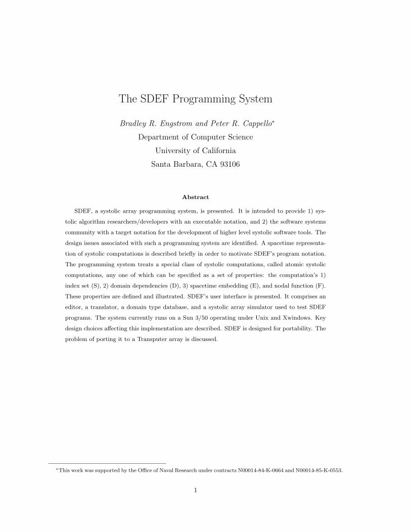
Figure 1: Overall structure of SDEF system.
to Pascal, but also provides interprocessor communication primitives based on message passing. Poker
[?] uses several program abstractions that unify parallel programming. The Poker environment has
been targeted to 1) the ChiP [?], 2) hypercubes [?], and 3) systolic arrays (Hearts [?]). Hearts, a
specialization of the Poker programming environment, integrates the process of specifying, compiling,
loading, and tracing systolic computations. Occam, W2, and Poker are significant achievements in
systolic array programming. These systems are intended to facilitate the production of executable
software for hardware arrays: they must provide a usable programming environment. Designers
of such systems must attend to such issues as the operating system and user interfaces, and the
interprocessor communication protocol.
1.3 The SDEF system
The SDEF system constitutes a programming environment for describing systolic algorithms. It
includes a notation for expressing systolic algorithms, a translator for the notation, and a systolic
array simulator with trace facilities.
The translator generates a C program that performs the computation specified by the SDEF
description. After being compiled, this C program can be run on the SDEF systolic array simulator.
Fig. ?? shows the overall structure of the SDEF environment.
An SDEF program specifies both the computation and communication requirements of a systolic
algorithm. The SDEF program also specifies how the systolic algorithm is to be ‘embedded’ in
2
spacetime [?]. This approach differs from that used by Occam, W2, and Hearts. These differences
are examined in § ??. The goals of the SDEF system are to:
• Increase the productivity of systolic algorithm researchers.
SDEF provides a notation for systolic computations that is precise and executable. Algorithms
can be communicated succinctly in a form that is suitable for independent testing and use by
others.
• Increase the productivity of systolic algorithm developers.
Data communication 1) between array processors, and 2) between peripheral processors and the
file system, is described implicitly in an SDEF program. The SDEF translator (and not the
user) creates a C program wherein all data communication is made explicit.
Reliability is enhanced because parts of SDEF programs are reusable, and because SDEF pro-
vides extensive trace facilities for testing algorithm descriptions.
• Support work by others on very high level systolic languages.
The SDEF notation is not intended to be the ultimate systolic programming language. Higher
level languages are contemplated. Indeed, some are under development. Chen’s Crystal [?], a
general framework for synthesizing parallel systems, can be specialized to systolic processing [?].
Delosme and Ipsen have started work on a system for producing optimal spacetime embedding
of affine recurrence equations [?]. The mapping a systolic computation onto an undersized array
has been addressed, for example, by Fortes and Moldovan [?, ?, ?], and Navarro, Llaberia, and
Valero [?]. There has been much research conducted into tools for analyzing [?, ?, ?, ?, ?, ?, ?, ?]
systolic algorithms, as well as synthesizing [?, ?, ?, ?, ?], and optimizing [?] them. SDEF does
not subsume these tools. Where automated, such tools can be connected to SDEF’s front-end:
SDEF can be used to express the results of the analyses, syntheses, and optimizations performed
by other tools.
2 Issues in Systolic Computation Specification
2.1 Systolic array programming
Before discussing the general issues of systolic programming, we examine the methods for program-
ming systolic arrays provided by W2 and Hearts. Since W2 is different from Hearts, and both are
different from SDEF, they provide a good basis for comparison.
3
2.1.1 W2
The language W2 was developed to program the Warp processor array. The user views the Warp
system as a linear array of identical processors which can communicate with their left and right
neighbors. Communication is based on message passing. The receive primitive has four parameters:
1) the direction from which the data is to be read, 2) the name of the channel, 3) the variable
to which the data is to be assigned, and 4) the name of an external variable from which to get
the data, if the receive is performed by a peripheral processor. Communication is explicit: It is
the programmer’s responsibility to ensure that data flows correctly, and that sends match receives.
Explicit communication is widely used in parallel programming systems. A well known example is
the send and receive primitives of Hoare’s CSP language.
2.1.2 Hearts
Hearts is a derivative of the Poker programming environment. Hearts provides an integrated set of
tools to create, run, trace, and debug systolic programs. The Hearts environment provides graphical
metaphors to simplify programming. Creating a Hearts program is a five-step process:
1. Create the communication structure
The programmer requests a one- or two-dimensional array of processors. Then, using the mouse
and keyboard, the programmer “draws” the communication links between processors, thus spec-
ifying the communication graph of the systolic array. Since the interconnection structure for
systolic arrays is usually regular, commands are available for specifying an iterative structure.
2. Write the nodal functions
Using a text editor, the programmer writes the sequential code that will run on each proces-
sor. The language used incorporates primitives to read and write data to a port (a named
communication path). There may be more than one nodal function.
3. Assign processes to processors
After writing one or more nodal functions each processor is assigned the function it is to execute.
Any actual parameters to the nodal function are entered at this time.
4. Assign port names to communication links
Communication links between processors are defined in the first step. In order to refer to them
in the nodal code, each link is given a name, known as the port name.
5. Assign stream names
Input and output at the periphery of the array requires data to be read or written to files. A
stream name associates file names with input and output ports. It also specifies the index of
4
data within the file that is to be associated with each port. Record boundaries can be located
because data item sizes must be fixed.
Both W2 and Hearts use explicit commands to pass messages. In Hearts, a graphical tool is used to
specify the communication structure and size of the array. Since the Warp has a fixed architecture, this
kind of tool is not needed in the Warp environment. Hearts obtains external data from the underlying
Unix file system; W2 uses a shared memory paradigm to access data on the host computer.
The differences in these two systems stem from differences in their goals. The W2 project is
working to create a very high speed parallel processing engine. The intent of the Hearts project is to
provide a programming environment that facilitates the creation of systolic programs.
2.2 Higher level notation
Hearts and W2 are examples of message-based programming: sends and receives are used to pass
messages. It is the programmer’s responsibility to coordinate processes so that sends and receives
match. This method is simple to understand, in principle, because the program mirrors the underlying
operational mechanisms. It also tends to result in efficient code. Message-based programming however
can be error prone, especially when the communication pattern is complex. Systolic algorithms and
applications are becoming increasingly complex. A higher level notation for programming systolic
arrays is needed to help programmers cope with this increased complexity.
2.3 Systolic programming issues
Many of the issues in systolic programming have analogues in sequential programming. The com-
plexity of parallel programming increases the importance of some of these issues, such as program
re-usability. This section, though not exhaustive, examines some of the important issues in the design
of a systolic programming environment:
• Interface issues
Operating system: The systolic programming system should provide the array programmer
with a natural interface to the operating system of the host computer.
External I/O: Usually in a systolic array, only the peripheral processors access the host or
external I/O devices. This complicates the programmed communication of data and pro-
gram to, and from, the systolic array. The programming system must enable the user to
handle gracefully this constraint on external communication. The environment should help
the user to ensure that data is ordered and formated correctly.
5
• Program issues The reason for creating a programming environment is to make programming
simpler (hence more reliable) and faster.
Creation/Modification: Specialized tools are needed to create and modify programs. Pro-
gramming systems, such as Poker, that provide a complete set of tools are essential.
Error detection: The systolic programming system should be designed to detect as many
program errors as possible, as soon as they are committed.
Testing: As systolic programs become more complex, the need for high-level testing and eval-
uation tools increases. A systolic programming environment should provide specialized
facilities for tracing and debugging systolic array programs.
Re-usability: Distinct systolic programs often have one or more components in common, such
as their communication pattern. In order to increase programmer productivity, the pro-
gramming language should provide for the re-use of common program components.
Efficiency: In systolic systems, just as in conventional systems, there is usually a tradeoff
between speed and ease of use. High level systolic languages typically incur more overhead
than low level languages. It is however generally accepted that the advantages of high level
languages justify their cost, except in extremely time critical applications.
3 Spacetime Representations
Programming in SDEF is based on a spacetime representation of systolic computations[?, ?]. This
section briefly introduces this idea.
3.1 Spacetime representation of systolic computations
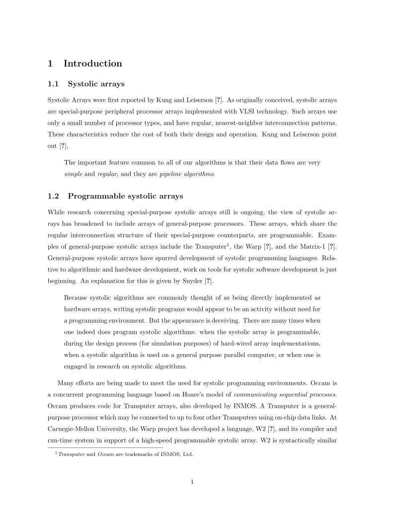
The following code fragment computes a matrix-vector product, y = Ax, for a 3 × 3 array A, and
vectors y and x.for i = 1 to 3 do
y[i] = 0;
for j = 1 to 3 do
y[i] = y[i] + A[i,j] * x[j]; /* inner product step */
end
end
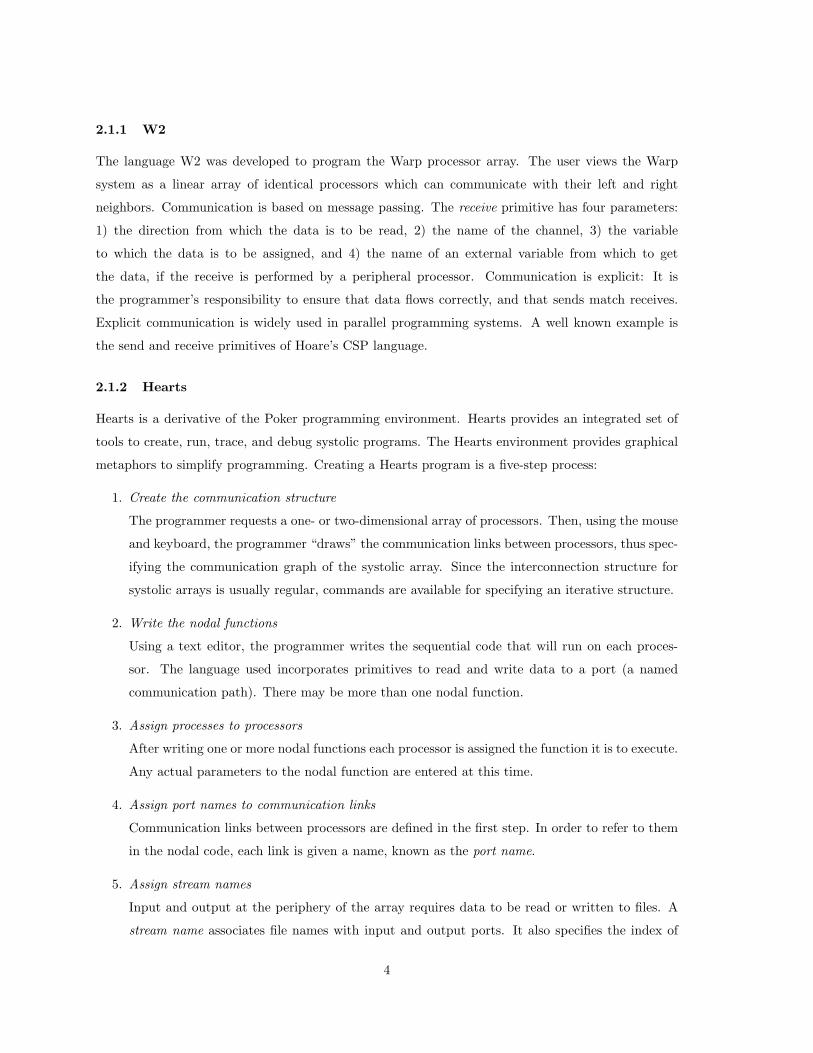
If we “unravel” the for loops we can represent the computation with respect to data usage. Such
a diagram, for the above code, is given in Fig. ??. The figure depicts the data dependence of each
inner product step (IPS). There is one IPS process for each entry in the A matrix. It is convenient to
6
¹¸
º·
¹¸
º·
¹¸
º·
¹¸
º·
¹¸
º·
¹¸
º·
¹¸
º·
¹¸
º·
¹¸
º·
6
6
6
6 6 6
66
6 6
6 6
-
-
- -
-
- -
-
-A11
A12
A13
A21
A22
A23
A31
A32
A33
Y1 Y2 Y3
X1
X2
X3
X1
X2
X3
X1
X2
X3
Figure 2: Data usage in matrix-vector product.
¹¸
º·`¹¸
º·
¹¸
º·
¹¸
º·
¹¸
º·
¹¸
º·
¹¸
º·
¹¸
º·
¹¸
º·
6
-
- - -
- - -
- - -
6
6
6
6 6 6
6
66
6 66
6
6
6
6
A11
A12
A13
A21
A22
A23
A31
A32
A33P3
P2
P1
Y1 Y2 Y3
X1
X2
X3
Time
Space
-
-
-
1 2 3
1
2
3
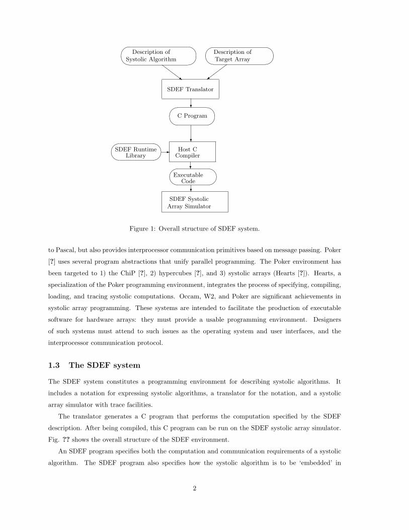
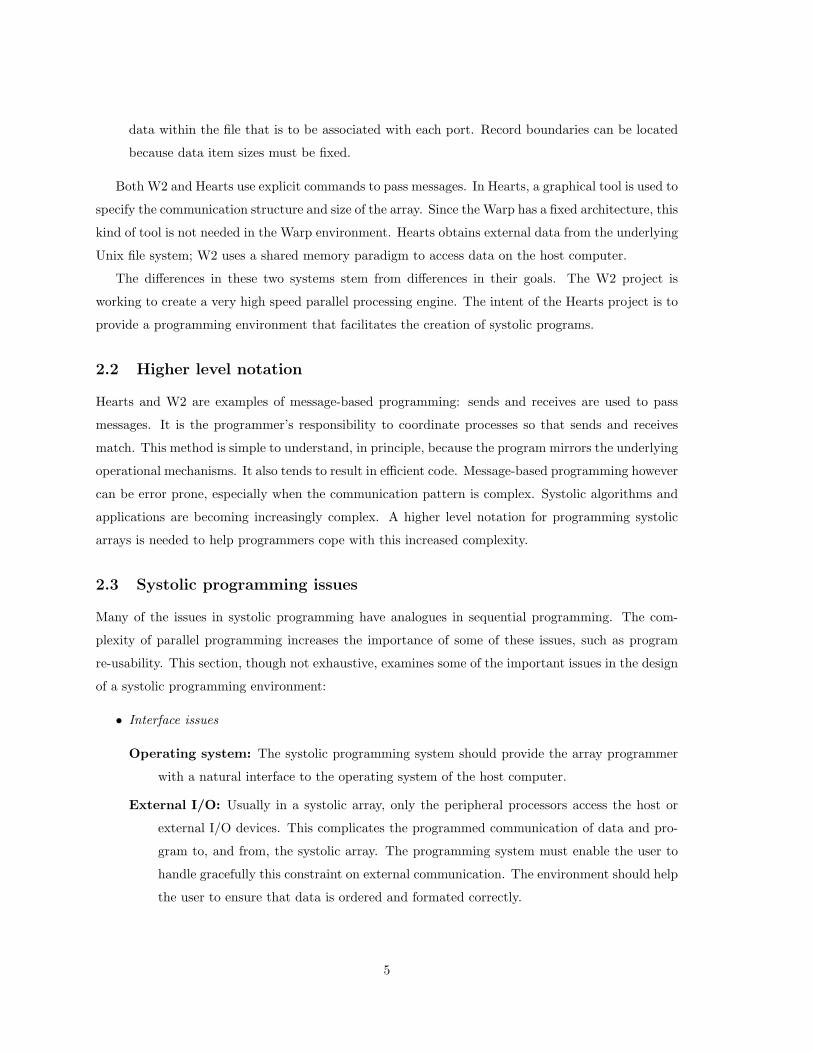
Figure 3: Spacetime representation of matrix-vector product.
associate each process with its corresponding A element index, which we refer to as its process index.
We can create another representation of matrix-vector product by using a spacetime diagram.
Similar to Fig. ??, this diagram depicts the data dependence (between inner product processes) in
space and time. A spacetime diagram of matrix-vector product is shown in Fig. ??. We refer to this
as the initial design for matrix-vector product. In this design, there are three processors, and three
time cycles. The value for yi is computed in cycle i. The diagram indicates that the three processes
associated with a y component are all performed during the same cycle. In fact, process(i,1) must
complete before process(i,2) starts, which in turn must complete before process(i,3) starts. In this
design, which would never be used, the time/cycle thus depends on the size of the matrix. Processor
P1 starts with an initial value of 0 for yi, then executes the IPS function (i.e., the inner product step)
using the values for x1 and Ai1 that it received. The result, the new value of yi, is passed to P2. The
final value of yi is output by P3.
The position of each node in spacetime (its process index) indicates where and when an IPS
7
¹¸
º·¹¸
º·¹¸
º·
¹¸
º·
¹¸
º·
¹¸
º·
¹¸
º·
¹¸
º·
¹¸
º·
6
6
6
6
6
6?
?
?
?
?
?
¡¡µ
¡¡µ
¡¡µ
¡¡µ
¡¡µ
¡¡µ@
@R
@@R
@@R
@@R
@@R
6
A11
A12
A13
A21
A22
A23
A31
A32
A33
Space
Time
P1
P2
P3
P4
P5
@@R
@@
@R
@@
@@R
@@@R
¡¡¡µ
¡¡
¡¡µ
¡¡¡µ
¡¡¡µ
¡¡¡µ
¡¡
¡¡µ
@@@R
@@
@@R
@@
@R
>
~
Y1 Y2
Y3
µ
RX1
X2 X3
Y3Y2
Y1X3
X2X1
-0 1 2 3 4 5 6 7 8
-2
-1
0
1
2
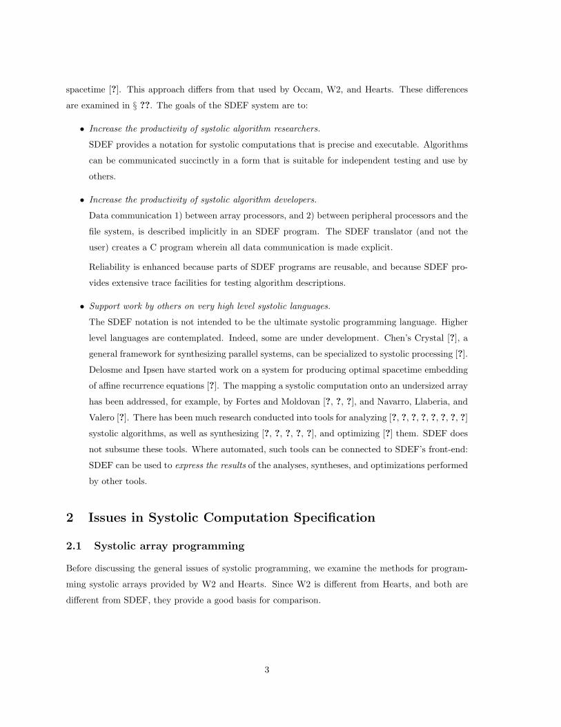
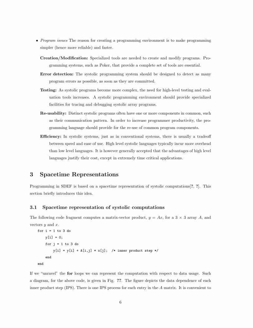
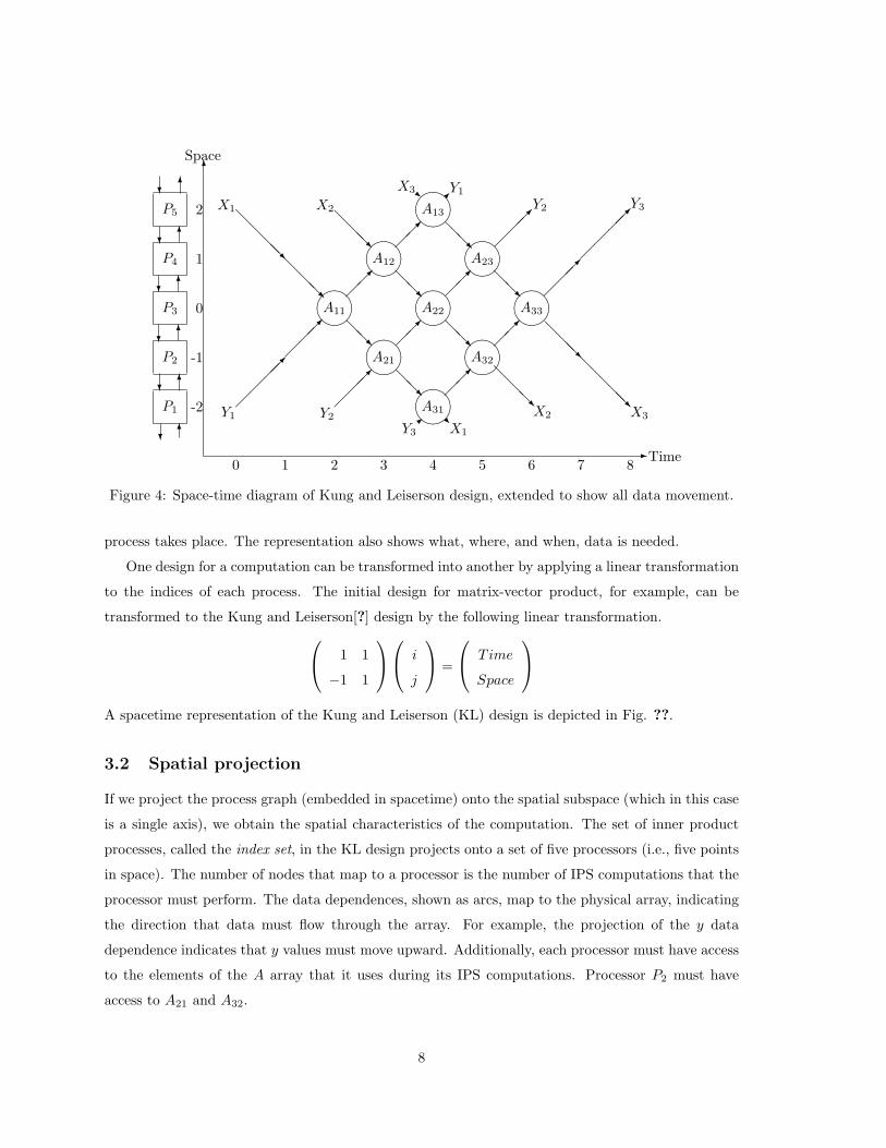
Figure 4: Space-time diagram of Kung and Leiserson design, extended to show all data movement.
process takes place. The representation also shows what, where, and when, data is needed.
One design for a computation can be transformed into another by applying a linear transformation
to the indices of each process. The initial design for matrix-vector product, for example, can be
transformed to the Kung and Leiserson[?] design by the following linear transformation. 1 1
−1 1
i
j
=
Time
Space
A spacetime representation of the Kung and Leiserson (KL) design is depicted in Fig. ??.
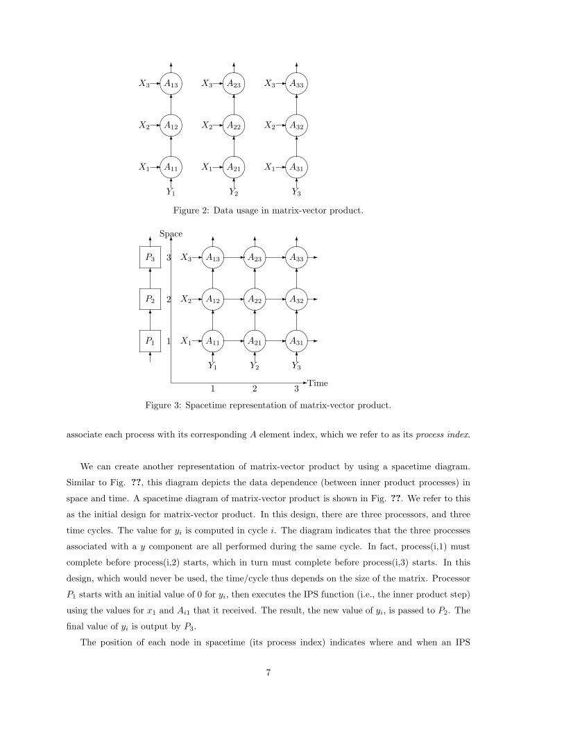
3.2 Spatial projection
If we project the process graph (embedded in spacetime) onto the spatial subspace (which in this case
is a single axis), we obtain the spatial characteristics of the computation. The set of inner product
processes, called the index set, in the KL design projects onto a set of five processors (i.e., five points
in space). The number of nodes that map to a processor is the number of IPS computations that the
processor must perform. The data dependences, shown as arcs, map to the physical array, indicating
the direction that data must flow through the array. For example, the projection of the y data
dependence indicates that y values must move upward. Additionally, each processor must have access
to the elements of the A array that it uses during its IPS computations. Processor P2 must have
access to A21 and A32.
8

3.3 Temporal projection
By projecting the process graph onto the temporal axis, we obtain the cycle in which each process
is executed. The first IPS process cycle (i.e., the node in the process graph with the smallest time
index) occurs in processor P3. The IPS function requires an x component, a y component, and an
element of A. The x and y values must be passed to this center processor by its immediate neighbors.
By extending the data arcs in spacetime, we create a schedule for data delivery from the peripheral
processors. This is given in Fig. ??, which portrays what each processor must do at each cycle. As
an example, the actions prescribed for the first three cycles are given in Fig. ??.
Cycle Actions
0 P5 read the value for x1 and passes it to P4.
P1 reads the value for y1 and passes it to P2.
1 P4 read the value for x1 and passes it to P3.
P2 reads the value for y1 and passes it to P3.
2 P5 reads x2 and passes it to P4.
P3 reads y1 from P2, reads x1 from P4 and executes an IPS.
The new y1 is passed to P4, and x1 is passed to P2.
P1 reads y2 and passes it to P2.
Figure 5: Processor actions during cycles 0,1 and 2.
3.4 Transforming computations
A systolic algorithm is realized by linearly embedding a cellular processes graph in spacetime. Different
linear maps result in systolic designs with different sets of processor arrays, communication patterns,
and relative communication rates. This mathematical mechanism is an important part of the SDEF
programming system.
4 Specifying a Systolic Computation Using SDEF
SDEF programs are based primarily on the spacetime representation introduced in Section ??. In
this section, we introduce the four properties used in SDEF to describe a systolic computation.
4.1 The properties of an atomic systolic computation
SDEF treats a subset of systolic computations. This subset is the one treated in the work of [?, ?, ?, ?].
The computational fragments informally correspond to computing uniform recurrence equations inside
9
¹¸
º·¹¸
º·¹¸
º·¹¸
º·¹¸
º·
¹¸
º·
¹¸
º·
¹¸
º·
¹¸
º·
¹¸
º·
¹¸
º·
¹¸
º·
¹¸
º·
¹¸
º·
¹¸
º·
1,1
1,2
1,3
1,4
1,5
2,2
2,3
2,4
2,5
3,3
3,4
3,5
4,4
4,5 5,56
- i
j
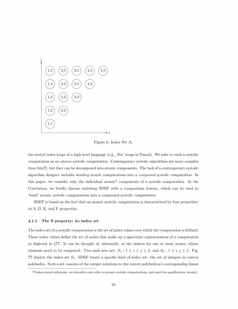
Figure 6: Index Set S1
the nested index loops of a high level language (e.g., ‘For’ loops in Pascal). We refer to such a systolic
computation as an atomic systolic computation. Contemporary systolic algorithms are more complex
than this[?], but they can be decomposed into atomic components. The task of a contemporary systolic
algorithm designer includes bonding atomic computations into a compound systolic computation. In
this paper, we consider only the individual atomic2 components of a systolic computation. In the
Conclusion, we briefly discuss enriching SDEF with a composition feature, which can be used to
‘bond’ atomic systolic computations into a compound systolic computation.
SDEF is based on the fact that an atomic systolic computation is characterized by four properties:
its S, D, E, and F properties.
4.1.1 The S property: its index set
The index set of a systolic computation is the set of index values over which the computation is defined.
These index values define the set of nodes that make up a spacetime representation of a computation
as depicted in §??. It can be thought of, informally, as the indices for one or more arrays, whose
elements need to be computed. Two such sets are: S1 : 1 ≤ i ≤ j ≤ 5, and S2 : 1 ≤ i, j ≤ 5. Fig.
?? depicts the index set S1. SDEF treats a specific kind of index set: the set of integers in convex
polyhedra. Such a set consists of the integer solutions to the convex polyhedron’s corresponding linear
2Unless stated otherwise, we hereafter only refer to atomic systolic computations, and omit the qualification ‘atomic.’
10
¾
?
¾¡
¡¡¡ª ?
x:(-1,0) x:(-1,0)
y:(0,-1) a:(0,-1)y:(-1,-1)
a:(0,0)
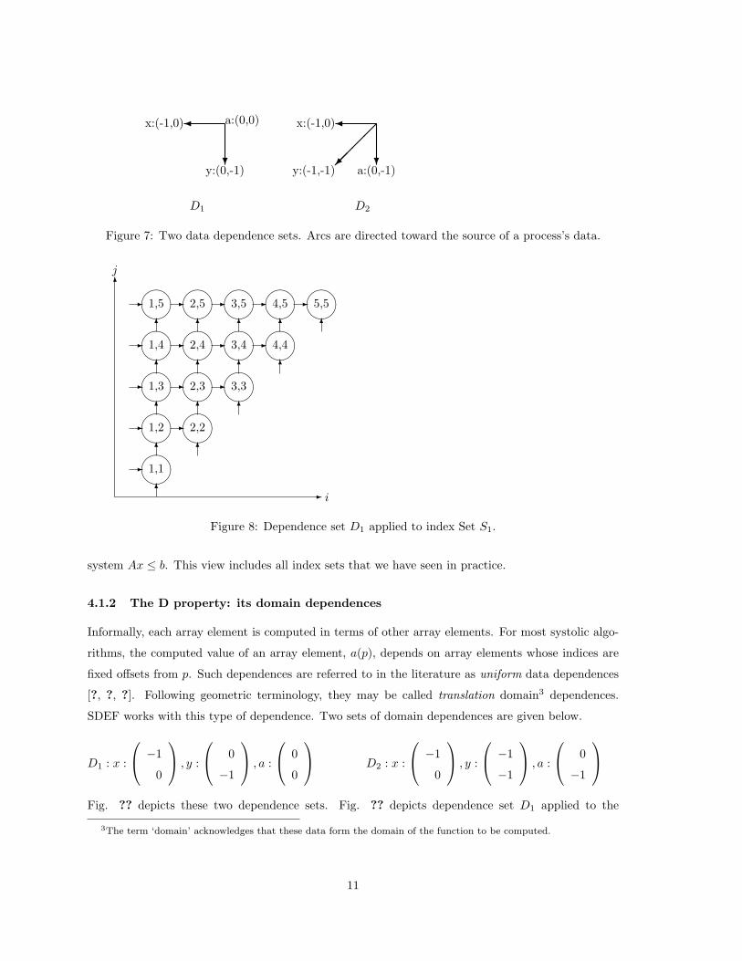
D1 D2
Figure 7: Two data dependence sets. Arcs are directed toward the source of a process’s data.
¹¸
º·¹¸
º·¹¸
º·¹¸
º·¹¸
º·
¹¸
º·
¹¸
º·
¹¸
º·
¹¸
º·
¹¸
º·
¹¸
º·
¹¸
º·
¹¸
º·
¹¸
º·
¹¸
º·
1,1
1,2
1,3
1,4
1,5
2,2
2,3
2,4
2,5
3,3
3,4
3,5
4,4
4,5 5,56
- i
j
-
-
-
-
-
- - - -
- - -
- -
-
6
6
6
6
6 6 6 6 6
66
6
6
6
6
Figure 8: Dependence set D1 applied to index Set S1.
system Ax ≤ b. This view includes all index sets that we have seen in practice.
4.1.2 The D property: its domain dependences
Informally, each array element is computed in terms of other array elements. For most systolic algo-
rithms, the computed value of an array element, a(p), depends on array elements whose indices are
fixed offsets from p. Such dependences are referred to in the literature as uniform data dependences
[?, ?, ?]. Following geometric terminology, they may be called translation domain3 dependences.
SDEF works with this type of dependence. Two sets of domain dependences are given below.
D1 : x :
−1
0
, y :
0
−1
, a :
0
0
D2 : x :
−1
0
, y :
−1
−1
, a :
0
−1
Fig. ?? depicts these two dependence sets. Fig. ?? depicts dependence set D1 applied to the
3The term ‘domain’ acknowledges that these data form the domain of the function to be computed.
11
index set S1. By convention, the data arcs are directed toward the process that uses the data. This
is the opposite direction of domain dependence vectors, which point to the source of the data, not its
destination.
4.1.3 The E property: its spacetime embedding
A process graph can be scheduled on an array of processors in many ways. One topic of systolic array
research is concerned with linear embeddings of these process graphs into spacetime. Different systolic
arrays in the literature often are just linear transformations of one another in spacetime[?, ?, ?, ?, ?, ?].
A guide to the literature concerned with such manipulations is given by Fortes and Wah[?]. Two
examples of spacetime embeddings are given below.
E1 :
1 1
−1 1
i
j
=
Time
Space
E2 :
1 1
1 0
0 1
i
j
=
Time
Space1
Space2
.
Figure ?? depicts a linear transformation of Fig. ??.
4.1.4 The F property: its process function
In an atomic systolic computation, all processes compute the same function. The function’s domain
can contain the process index. Apart from the process index, the function’s domain equals its co-
domain. We give below two different functions that have the same number of inputs and outputs.
F1(input:x,y,a:output:x’,y’,a’)
integer x, y, a;
{ x’ ← x; a’ ← a; y’ ← y + a × x; }
F2(input:x,y,a:output:x’,y’,a’)
char x, a; boolean y;
{ x’ ← x; a’ ← a; y’ ← y and (a == x); }The property values described above can be combined in a variety of ways. Five distinct designs
based on these property values are given below.
1. Upper triangular matrix-vector product: U = (S1, D1, E1, F1).
2. By changing the index space, we obtain a design for Full Matrix-Vector Product: M =
(S2, D1, E1, F1) 4.
3. By changing the domain dependences, we obtain a design for Polynomial Product (convolution):
C = (S2, D2, E1, F1).
4This bidirectional linear systolic array for computing matrix-vector product was first reported by Kung et al.[?]
12
4. By changing the function computed at each vertex, we obtain a design for String Pattern
Matching: S = (S2, D2, E1, F2).
5. By changing the spacetime embedding, we obtain a design for String Pattern Matching that is
completely pipelined, operating on a hexagonally-connected array: P = (S2, D2, E2, F2).
As the above examples illustrate, systolic computations that are different, nonetheless may share
some properties. A good systolic programming environment should facilitate the re-use of previously
established property values in the specification of a new systolic computation. Although the S,D,E
and F properties are largely independent, we note some weak interdependences:
• The dimension of the index space, dependence vectors, and embedding matrix all must agree.
• The number of domains must be equal to the number of arguments to the nodal function.
Distinct properties values thus can be readily substituted, resulting in distinct computations. The
S, D, and E properties are mathematical objects. Specifically, let C be an atomic systolic computation
of dimension d, and of function arity a. If C’s index space is the set of integers inside an m-sided
convex polygon, then its index space is characterized by a matrix S ∈ Zm×(d+1), where Z denotes
the integers. Each of its a domain dependences is a vector di ∈ Zd. If the dimension of spacetime
into which C is being embedded is l (l is typically 2 or 3), then its spacetime embedding is a matrix
E ∈ Zl×d.
4.2 Specifying the systolic array
SDEF’s target array is assumed to be a rectangular grid of orthogonally-connected processors. The
array’s size is specified as an ordered pair of integers (x, y), indicating that there are xy processors,
forming an x× y array. SDEF assumes that only peripheral processors have an I/O capability. The
I/O capability of these processors is expressed in terms of read and write capabilities for each bound-
ary of the array: left, right, top, and bottom. The capabilities that can be specified are: no capability,
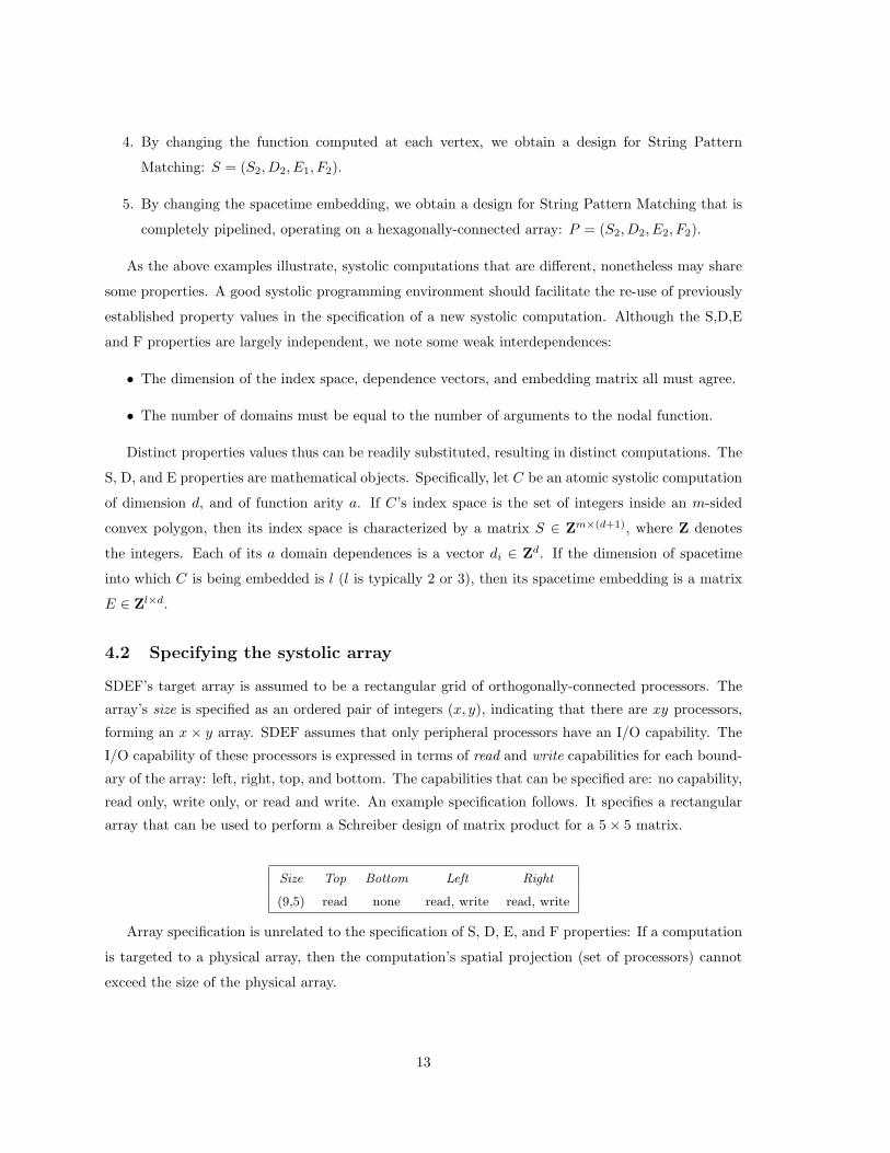
read only, write only, or read and write. An example specification follows. It specifies a rectangular
array that can be used to perform a Schreiber design of matrix product for a 5× 5 matrix.
Size Top Bottom Left Right
(9,5) read none read, write read, write
Array specification is unrelated to the specification of S, D, E, and F properties: If a computation
is targeted to a physical array, then the computation’s spatial projection (set of processors) cannot
exceed the size of the physical array.
13
4.3 Specifying the systolic computation
4.3.1 Specifying an S property
SDEF accommodates any index set that is the set of integers inside a convex polyhedron. Such a set
can be described as the integer solutions of a linear system Ax ≤ b. To specify such an index set, a
user first specifies the dimension of the computation (i.e., the number of independent indices). After
doing so, the the user can specify the A matrix and b vector that define the boundaries of the convex
polyhedron. In SDEF, these linear constraints are referred to as global constraints. In addition, a user
specifies orthohedral bounds. Orthohedral bounds specify lower and upper limits for an index (i.e., an
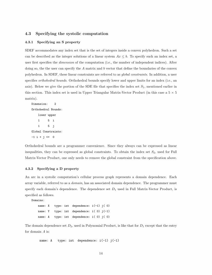
axis). Below we give the portion of the SDE file that specifies the index set S1, mentioned earlier in
this section. This index set is used in Upper Triangular Matrix-Vector Product (in this case a 5 × 5
matrix).Dimension: 2
Orthohedral Bounds:
lower upper
1 5 i
1 5 j
Global Constraints:
-1 i + j <= 0
Orthohedral bounds are a programmer convenience. Since they always can be expressed as linear
inequalities, they can be expressed as global constraints. To obtain the index set S2, used for Full
Matrix-Vector Product, one only needs to remove the global constraint from the specification above.
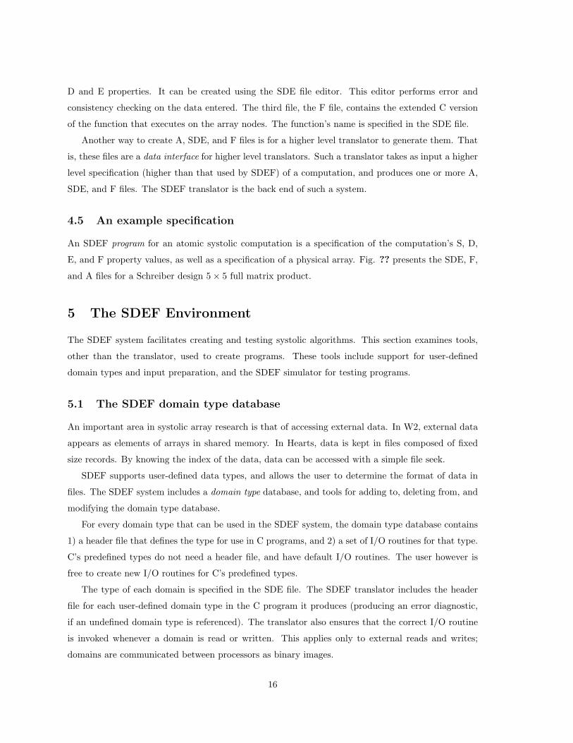
4.3.2 Specifying a D property
An arc in a systolic computation’s cellular process graph represents a domain dependence. Each
array variable, referred to as a domain, has an associated domain dependence. The programmer must
specify each domain’s dependence. The dependence set D1 used in Full Matrix-Vector Product, is
specified as follows.Domains:
name: X type: int dependence: i(-1) j( 0)
name: Y type: int dependence: i( 0) j(-1)
name: A type: int dependence: i( 0) j( 0)
The domain dependence set D2, used in Polynomial Product, is like that for D1 except that the entry
for domain A is:
name: A type: int dependence: i(-1) j(-1)
14

4.3.3 Specifying an E property
A computation’s spacetime embedding is specified as a matrix. The embedding map E1 used in the
Kung and Leiserson Matrix-Vector Product, for example, is specified as follows.Embedding: 1 1
-1 1
4.3.4 Specifying an F property
Function code is written in an SDEF-extended version of C. The idea of building on top of an existing
compiler for a sequential machine also has been used in the Poker programming environment [?]. The
C compiler is responsible for producing code for the target nodes, and for using their resources (e.g.,
registers, memory, and buffers) efficiently.
During each ‘computation cycle,’ the function code is invoked with its arguments. SDEF provides
two extensions to C: 1) prime notation, and 2) compiler-generated declarations. Prime notation
specifies the computed value of a domain. For example, the statement “Y ′ = Y + X + 1;” means
that the computed value of the domain Y is the argument value of Y plus the argument value of X
plus 1. Since data locations for Y ′ and Y are distinct, modification of one does not affect the other.
The SDEF translator translates domain references to internal data locations. The information in
these data locations is managed by code that is generated by the SDEF compiler. This code ensures
that data is moved between data locations and processors in the manner implied by the spacetime
embedding. Function code typically is only a small fraction of the program produced by the SDEF
translator.
For F1, mentioned earlier in this section, the user provides the following SDEF code.
F1(X,Y,A) { Y’ = Y + X * A; /* compute inner product step */ }
Variables Y’, Y, X, and A are not declared in the function code; the SDEF compiler inserts declarations
for all domains. The type of each domain is specified when the domain is specified. In SDEF notation,
a domain needs an explicit assignment statement only when it is modified by the function invocation.
As another example, the user provides the following code for F2 (the string pattern matching function).
F2(X,Y,W) { Y’ = Y && X == W; }
4.4 The specification environment
4.4.1 The SDE file
Property specifications are partitioned into 3 files. The A property, the array’s physical characteristics,
is specified in file A. The second file, the SDE file, contains the specification of a computation’s S,
15
D and E properties. It can be created using the SDE file editor. This editor performs error and
consistency checking on the data entered. The third file, the F file, contains the extended C version
of the function that executes on the array nodes. The function’s name is specified in the SDE file.
Another way to create A, SDE, and F files is for a higher level translator to generate them. That
is, these files are a data interface for higher level translators. Such a translator takes as input a higher
level specification (higher than that used by SDEF) of a computation, and produces one or more A,
SDE, and F files. The SDEF translator is the back end of such a system.
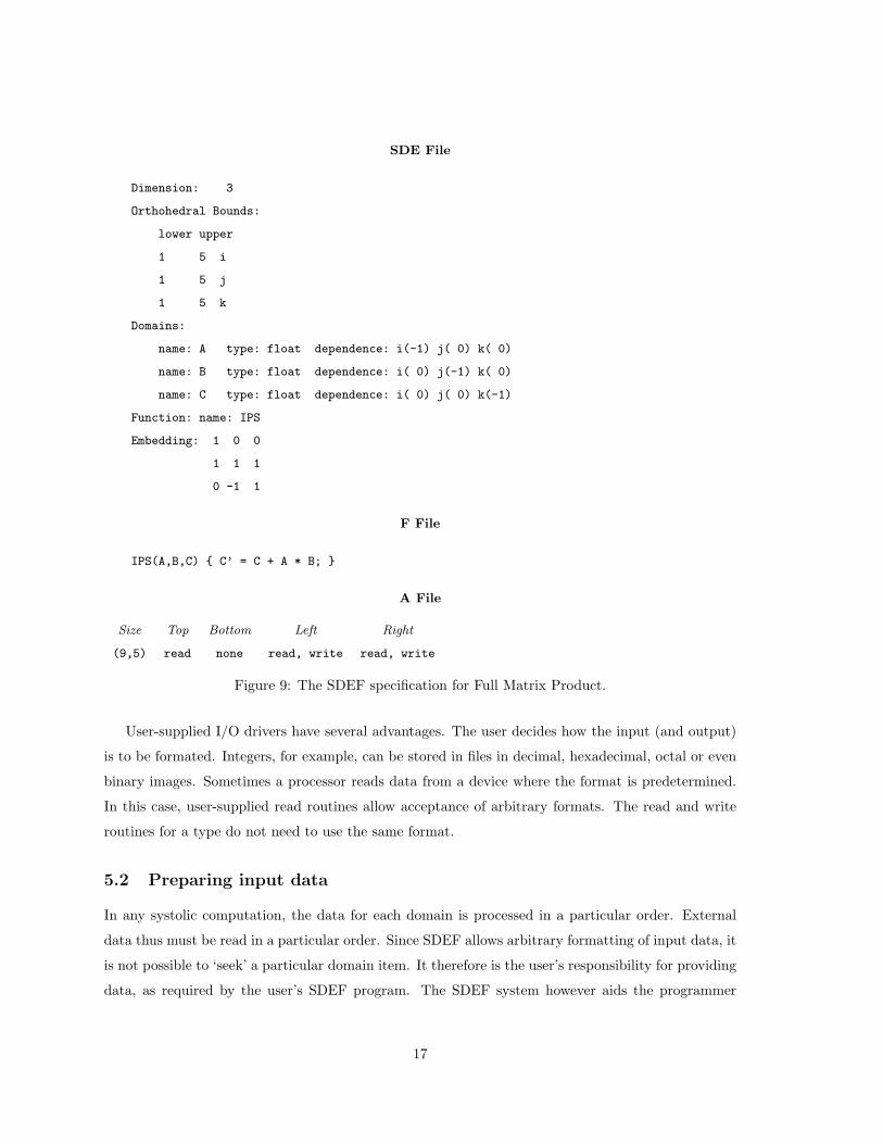
4.5 An example specification
An SDEF program for an atomic systolic computation is a specification of the computation’s S, D,
E, and F property values, as well as a specification of a physical array. Fig. ?? presents the SDE, F,
and A files for a Schreiber design 5× 5 full matrix product.
5 The SDEF Environment
The SDEF system facilitates creating and testing systolic algorithms. This section examines tools,
other than the translator, used to create programs. These tools include support for user-defined
domain types and input preparation, and the SDEF simulator for testing programs.
5.1 The SDEF domain type database
An important area in systolic array research is that of accessing external data. In W2, external data
appears as elements of arrays in shared memory. In Hearts, data is kept in files composed of fixed
size records. By knowing the index of the data, data can be accessed with a simple file seek.
SDEF supports user-defined data types, and allows the user to determine the format of data in
files. The SDEF system includes a domain type database, and tools for adding to, deleting from, and
modifying the domain type database.
For every domain type that can be used in the SDEF system, the domain type database contains
1) a header file that defines the type for use in C programs, and 2) a set of I/O routines for that type.
C’s predefined types do not need a header file, and have default I/O routines. The user however is
free to create new I/O routines for C’s predefined types.
The type of each domain is specified in the SDE file. The SDEF translator includes the header
file for each user-defined domain type in the C program it produces (producing an error diagnostic,
if an undefined domain type is referenced). The translator also ensures that the correct I/O routine
is invoked whenever a domain is read or written. This applies only to external reads and writes;
domains are communicated between processors as binary images.
16
SDE File
Dimension: 3
Orthohedral Bounds:
lower upper
1 5 i
1 5 j
1 5 k
Domains:
name: A type: float dependence: i(-1) j( 0) k( 0)
name: B type: float dependence: i( 0) j(-1) k( 0)
name: C type: float dependence: i( 0) j( 0) k(-1)
Function: name: IPS
Embedding: 1 0 0
1 1 1
0 -1 1
F File
IPS(A,B,C) { C’ = C + A * B; }
A File
Size Top Bottom Left Right
(9,5) read none read, write read, write
Figure 9: The SDEF specification for Full Matrix Product.
User-supplied I/O drivers have several advantages. The user decides how the input (and output)
is to be formated. Integers, for example, can be stored in files in decimal, hexadecimal, octal or even
binary images. Sometimes a processor reads data from a device where the format is predetermined.
In this case, user-supplied read routines allow acceptance of arbitrary formats. The read and write
routines for a type do not need to use the same format.
5.2 Preparing input data
In any systolic computation, the data for each domain is processed in a particular order. External
data thus must be read in a particular order. Since SDEF allows arbitrary formatting of input data, it
is not possible to ‘seek’ a particular domain item. It therefore is the user’s responsibility for providing
data, as required by the user’s SDEF program. The SDEF system however aids the programmer
17
by providing domain order templates for each domain. Such templates convey the order of domain
items by specifying the processor and cycle in which they are read. These files are computed by the
translator, based on the programmer’s specification of the index space and the spacetime embedding.
The domain order files can be used to ensure that either data in files is formated correctly, or data
from a device is generated in the proper order.
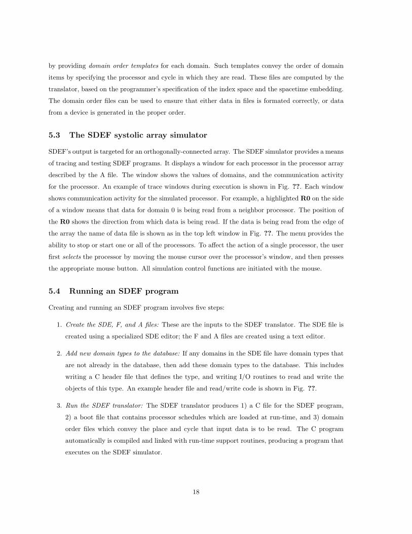
5.3 The SDEF systolic array simulator
SDEF’s output is targeted for an orthogonally-connected array. The SDEF simulator provides a means
of tracing and testing SDEF programs. It displays a window for each processor in the processor array
described by the A file. The window shows the values of domains, and the communication activity
for the processor. An example of trace windows during execution is shown in Fig. ??. Each window
shows communication activity for the simulated processor. For example, a highlighted R0 on the side
of a window means that data for domain 0 is being read from a neighbor processor. The position of
the R0 shows the direction from which data is being read. If the data is being read from the edge of
the array the name of data file is shown as in the top left window in Fig. ??. The menu provides the
ability to stop or start one or all of the processors. To affect the action of a single processor, the user
first selects the processor by moving the mouse cursor over the processor’s window, and then presses
the appropriate mouse button. All simulation control functions are initiated with the mouse.
5.4 Running an SDEF program
Creating and running an SDEF program involves five steps:
1. Create the SDE, F, and A files: These are the inputs to the SDEF translator. The SDE file is
created using a specialized SDE editor; the F and A files are created using a text editor.
2. Add new domain types to the database: If any domains in the SDE file have domain types that
are not already in the database, then add these domain types to the database. This includes
writing a C header file that defines the type, and writing I/O routines to read and write the
objects of this type. An example header file and read/write code is shown in Fig. ??.
3. Run the SDEF translator: The SDEF translator produces 1) a C file for the SDEF program,
2) a boot file that contains processor schedules which are loaded at run-time, and 3) domain
order files which convey the place and cycle that input data is to be read. The C program
automatically is compiled and linked with run-time support routines, producing a program that
executes on the SDEF simulator.
18

Figure 10: SDEF trace windows during execution.
19
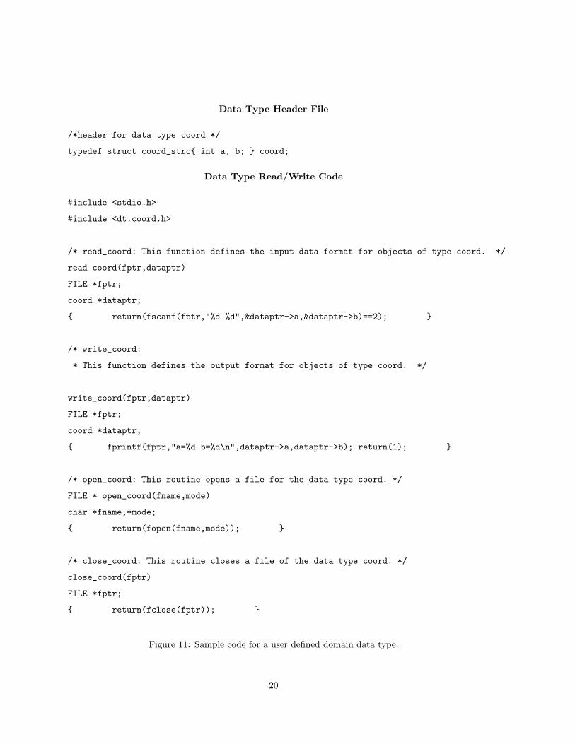
Data Type Header File
/*header for data type coord */
typedef struct coord_strc{ int a, b; } coord;
Data Type Read/Write Code
#include <stdio.h>
#include <dt.coord.h>
/* read_coord: This function defines the input data format for objects of type coord. */
read_coord(fptr,dataptr)
FILE *fptr;
coord *dataptr;
{ return(fscanf(fptr,"%d %d",&dataptr->a,&dataptr->b)==2); }
/* write_coord:
* This function defines the output format for objects of type coord. */
write_coord(fptr,dataptr)
FILE *fptr;
coord *dataptr;
{ fprintf(fptr,"a=%d b=%d\n",dataptr->a,dataptr->b); return(1); }
/* open_coord: This routine opens a file for the data type coord. */
FILE * open_coord(fname,mode)
char *fname,*mode;
{ return(fopen(fname,mode)); }
/* close_coord: This routine closes a file of the data type coord. */
close_coord(fptr)
FILE *fptr;
{ return(fclose(fptr)); }
Figure 11: Sample code for a user defined domain data type.
20
4. Create the input data files: Using the domain order files created by the translator, the user
creates files containing the actual data. The format of the data is determined by the I/O
routines for the data type in the domain type database. The order of stream data types is
determined by order of use during computation. Statics and initial register values are booted
at run-time. Their order is determined by the shape of the processor array, as given in the A
file.
5. Test the program using the SDEF simulator: Running the program on the simulator allows the
user to interactively monitor the program. The SDEF simulator automatically boots internal
tables and control files.
6 An Implementation of the SDEF System
6.1 The translator
The SDEF translator takes the A, SDE and F files as input and produces a C program to be run on
the processors of the systolic array.
The translator creates sequential code and control data, which, when executed, reproduces the
communication and computation structures described by the SDEF program. In this section, we
discuss some of the details of generating such a program.
6.1.1 Communication types
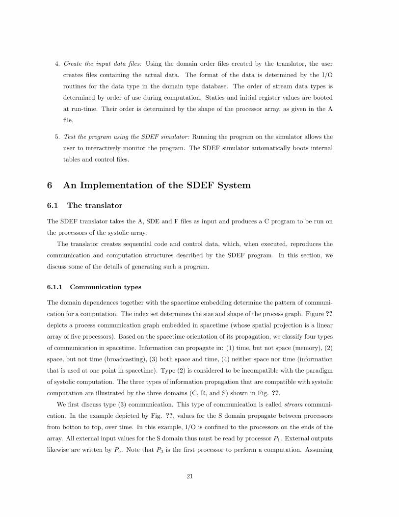
The domain dependences together with the spacetime embedding determine the pattern of communi-
cation for a computation. The index set determines the size and shape of the process graph. Figure ??
depicts a process communication graph embedded in spacetime (whose spatial projection is a linear
array of five processors). Based on the spacetime orientation of its propagation, we classify four types
of communication in spacetime. Information can propagate in: (1) time, but not space (memory), (2)
space, but not time (broadcasting), (3) both space and time, (4) neither space nor time (information
that is used at one point in spacetime). Type (2) is considered to be incompatible with the paradigm
of systolic computation. The three types of information propagation that are compatible with systolic
computation are illustrated by the three domains (C, R, and S) shown in Fig. ??.
We first discuss type (3) communication. This type of communication is called stream communi-
cation. In the example depicted by Fig. ??, values for the S domain propagate between processors
from botton to top, over time. In this example, I/O is confined to the processors on the ends of the
array. All external input values for the S domain thus must be read by processor P1. External outputs
likewise are written by P5. Note that P3 is the first processor to perform a computation. Assuming
21
-
¹¸
º·¹¸
º·¹¸
º·
¹¸
º·
¹¸
º·
¹¸
º·
¹¸
º·
¹¸
º·
¹¸
º·
6
6
6
6
6
6
¡¡µ
¡¡µ
¡¡µ
¡¡µ
¡¡µ
¡¡µ
6
C
C
C
C
C
C
C
C
C
Space
Time
P1
P2
P3
P4
P5
¡¡µ
¡¡µ
¡¡µ
S
S
S
- - -
- -
-
- -
-
R
R
R
R
R
Figure 12: A process graph embedded in spacetime whose spatial projection is a linear array of five
processors.
that the nodal function needs all three domains, this processor must wait for an initial S value to be
passed from P1. After a computation completes, results for domain S also need to be passed to P5 to
be written externally.
Type (1) communication, exemplified by domain R, is realized with a register. Registers are used
to realize domain dependences that have no spatial dependence, only a temporal one. The translator
detects this type of communication, generating the code to save and restore register values between
invocations of the nodal function.
Type (4) communication is called static ‘communication.’ Domain A is of this type. In static
communication, information propagates in neither space nor time. Such a piece of information can
be viewed as a constant embedded in spacetime.
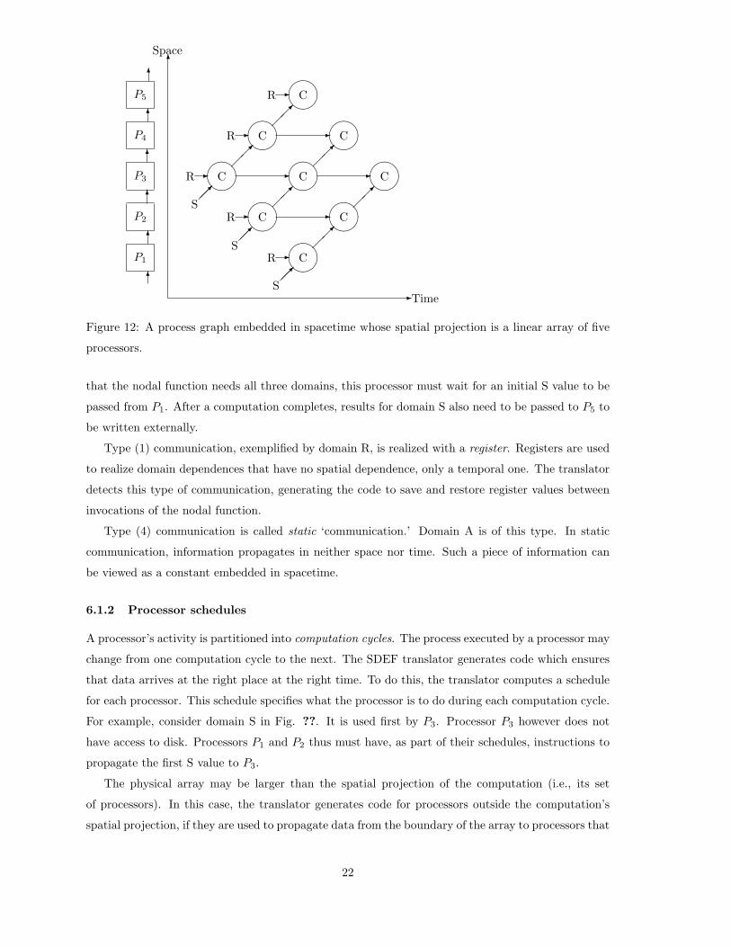
6.1.2 Processor schedules
A processor’s activity is partitioned into computation cycles. The process executed by a processor may
change from one computation cycle to the next. The SDEF translator generates code which ensures
that data arrives at the right place at the right time. To do this, the translator computes a schedule
for each processor. This schedule specifies what the processor is to do during each computation cycle.
For example, consider domain S in Fig. ??. It is used first by P3. Processor P3 however does not
have access to disk. Processors P1 and P2 thus must have, as part of their schedules, instructions to
propagate the first S value to P3.
The physical array may be larger than the spatial projection of the computation (i.e., its set
of processors). In this case, the translator generates code for processors outside the computation’s
spatial projection, if they are used to propagate data from the boundary of the array to processors that
22

participate in the computation. No code is generated for processors that have neither communication
nor computation tasks.
At present, the translator requires that the size of the physical array be at least as large as the
spatial projection of the embedded computation. That is, the translator does not automatically solve
the ‘partitioning’ problem for the user. Several systematic mapping techniques that solve this problem
are under consideration for inclusion into the SDEF system. In the meantime, extant research (see,
e.g., [?, ?, ?]) can be incorporated as a front-end to SDEF.
In addition to data propagation, a schedule includes information about whether the data comes
from a neighbor or from an external source. It also indicates when a function invocation is to occur
using the data obtained by the processor. When a function invocation occurs, the code generated
by the translator ensures that the nodal function is passed the correct domain values for all types of
domains: stream, register and static. After the nodal function is invoked, the modified domains are
propagated in spacetime as required by the user-specified spacetime embedding (E).
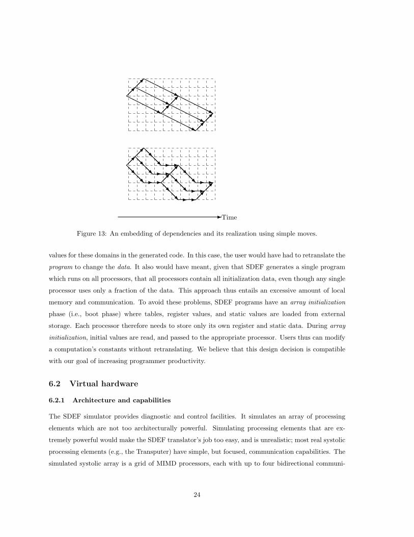
6.1.3 Translation data dependences
The SDEF translator processes dependence vectors that are not simply single steps in time and
space. A dependence can, for instance, specify that a domain value be communicated from a point
two units away in space, and three away in time. SDEF assumes an architecture in which each
processor can only send messages to its nearest neighbors. A dependence that requires a movement of
two spatial units over a period of three time units is converted to a sequence of physically realizable
communications called simple moves. A simple move is one where data moves 0 or 1 unit in space
in exactly one unit of time. Figure ?? depicts a spacetime embedding of a process graph, and the
resulting embedding after the embedded domain dependences have been realized as simple moves.
Each domain is propagated via a sequence of t stages, where t is the time component of its embedded
domain dependence vector. In order to realize an embedded domain dependence as a sequence of
simple moves, it is necessary and sufficient that∑d−1
i=1 si ≤ t, where the domain dependence, after
embedding in a d-dimensional spacetime, is of the form (t s1 s2 · · · sd−1)T , and where si is a spatial
component; t its time component.
6.1.4 Processor data
As depicted in Fig. ??, values for the S domain must be read from external storage. Data for stream
domains are read at run-time from edge processors. Data values for register and static domains are
stored internally by each virtual processor. There are many ways that SDEF could have been designed
to provide these values. This is especially problematical since, as in this example, all processors may
not have external read/write capability. The translator could have been designed to embed initial
23
HHHHHHjHHHHHHj
HHHHHHjHHHHHHj
HHHHHHjHHHHHHj
¡¡µ¡¡µ
¡¡µ¡¡µ
¡¡µ¡¡µ
@@R@@R - -
@@R@@R - -
@@R@@R - -
@@R@@R - -
@@R@@R - -
@@R@@R - -
¡¡µ¡¡µ
¡¡µ¡¡µ
¡¡µ¡¡µ
-Time
Figure 13: An embedding of dependencies and its realization using simple moves.
values for these domains in the generated code. In this case, the user would have had to retranslate the
program to change the data. It also would have meant, given that SDEF generates a single program
which runs on all processors, that all processors contain all initialization data, even though any single
processor uses only a fraction of the data. This approach thus entails an excessive amount of local
memory and communication. To avoid these problems, SDEF programs have an array initialization
phase (i.e., boot phase) where tables, register values, and static values are loaded from external
storage. Each processor therefore needs to store only its own register and static data. During array
initialization, initial values are read, and passed to the appropriate processor. Users thus can modify
a computation’s constants without retranslating. We believe that this design decision is compatible
with our goal of increasing programmer productivity.
6.2 Virtual hardware
6.2.1 Architecture and capabilities
The SDEF simulator provides diagnostic and control facilities. It simulates an array of processing
elements which are not too architecturally powerful. Simulating processing elements that are ex-
tremely powerful would make the SDEF translator’s job too easy, and is unrealistic; most real systolic
processing elements (e.g., the Transputer) have simple, but focused, communication capabilities. The
simulated systolic array is a grid of MIMD processors, each with up to four bidirectional communi-
24
m
m
m
mmm
m
m
m
m n m±°²¯ n Linear Array
Processor Grid
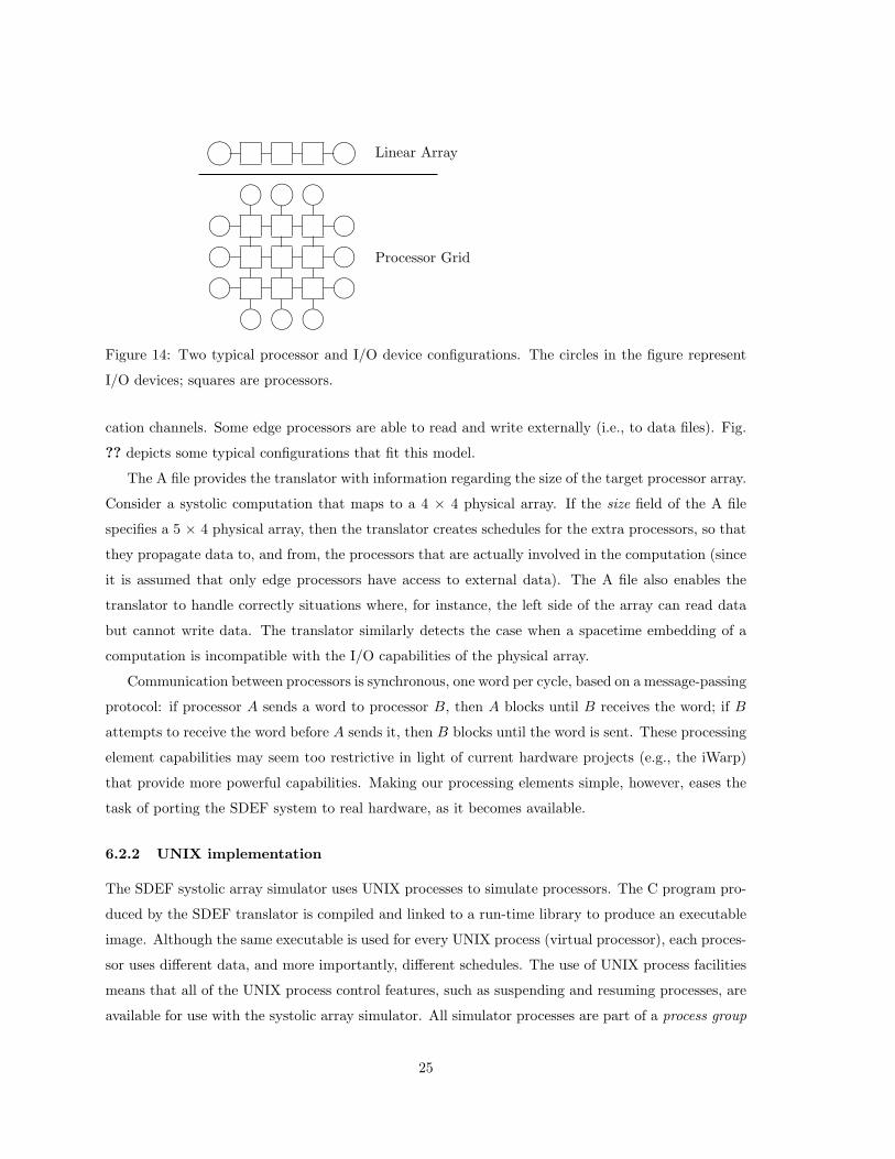
Figure 14: Two typical processor and I/O device configurations. The circles in the figure represent
I/O devices; squares are processors.
cation channels. Some edge processors are able to read and write externally (i.e., to data files). Fig.
?? depicts some typical configurations that fit this model.
The A file provides the translator with information regarding the size of the target processor array.
Consider a systolic computation that maps to a 4 × 4 physical array. If the size field of the A file
specifies a 5 × 4 physical array, then the translator creates schedules for the extra processors, so that
they propagate data to, and from, the processors that are actually involved in the computation (since
it is assumed that only edge processors have access to external data). The A file also enables the
translator to handle correctly situations where, for instance, the left side of the array can read data
but cannot write data. The translator similarly detects the case when a spacetime embedding of a
computation is incompatible with the I/O capabilities of the physical array.
Communication between processors is synchronous, one word per cycle, based on a message-passing
protocol: if processor A sends a word to processor B, then A blocks until B receives the word; if B
attempts to receive the word before A sends it, then B blocks until the word is sent. These processing
element capabilities may seem too restrictive in light of current hardware projects (e.g., the iWarp)
that provide more powerful capabilities. Making our processing elements simple, however, eases the
task of porting the SDEF system to real hardware, as it becomes available.
6.2.2 UNIX implementation
The SDEF systolic array simulator uses UNIX processes to simulate processors. The C program pro-
duced by the SDEF translator is compiled and linked to a run-time library to produce an executable
image. Although the same executable is used for every UNIX process (virtual processor), each proces-
sor uses different data, and more importantly, different schedules. The use of UNIX process facilities
means that all of the UNIX process control features, such as suspending and resuming processes, are
available for use with the systolic array simulator. All simulator processes are part of a process group
25
and thus can be manipulated as a whole. There is also a master process which handles input from
the user, and can start and stop virtual processors on command. The disadvantage of using UNIX
processes is that there are a limited number of them. In the current implementation, the process
limit is over 50. Since systolic algorithms scale, testing can be done on a small array. This UNIX
limitation thus has not been too restrictive. Interprocess communication is done using UNIX sockets.
External data is read and written using UNIX files. Each simulator process has a window associated
with it that displays internal data, and communication activity. Due to limited screen space, the
largest array that currently can be displayed is a 6× 6 grid. The use of display windows is optional;
the simulator can be used without them.
6.3 Portability
Consider what is necessary to retarget the SDEF translator, and to port the run-time system, to
an INMOS Transputer system. A Transputer system consists of a host computer connection to an
array of processors. Each processor has four I/O channels that can be used to link them. The
INMOS system provides a Transputer C compiler, and a library of routines used for I/O and inter-
Transputer communication. The SDEF translator would run on the host computer, and does not
need to be modified; all system-dependent features are encapsulated in SDEF library routines. The
code generated by the translator references routines in this interface library.
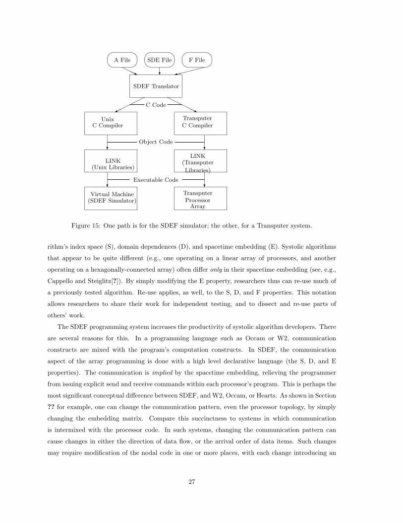
To port SDEF to a Transputer environment, the SDEF run-time system needs to be modified
in two places. First, the UNIX calls that spawn processes and establish connections between them
are replaced by calls to the Transputer library routines providing these services. Second, the send
and receive calls between processors are changed from UNIX socket calls to Transputer library calls.
Figure ?? depicts the paths for creating programs for the SDEF simulator, and for a Transputer array.
The SDEF system reduces the translator’s dependence on particular hardware capabilities by 1)
using C as the target language for the translator, and 2) encapsulating hardware-specific code. These
measures enhance SDEF’s portability. Although the translator is relatively hardware independent,
the run-time system needs to be tailored to each implementation; the run-time system displays trace
information, and maintains the view of the array as an orthogonally-connected mesh.
7 Conclusions
The SDEF programming system increases the productivity of systolic algorithm researchers. Having
a mathematical basis, SDEF provides a notation for specifying atomic systolic computations that is
succinct, precise, and executable. The communication requirements are specified in terms of the algo-
26
¶
µ
³
´
¶
µ
³
´
¶
µ
³
´»»»»»9HHHj ?
©©©©©¼
HHHHHj
?
? ?
?
C Code
Object Code
Executable Code
A File SDE File F File
SDEF Translator
UnixC Compiler
TransputerC Compiler
LINK(Unix Libraries)
LINK(Transputer
Libraries)
Virtual Machine(SDEF Simulator)
TransputerProcessor
Array
Figure 15: One path is for the SDEF simulator; the other, for a Transputer system.
rithm’s index space (S), domain dependences (D), and spacetime embedding (E). Systolic algorithms
that appear to be quite different (e.g., one operating on a linear array of processors, and another
operating on a hexagonally-connected array) often differ only in their spacetime embedding (see, e.g.,
Cappello and Steiglitz[?]). By simply modifying the E property, researchers thus can re-use much of
a previously tested algorithm. Re-use applies, as well, to the S, D, and F properties. This notation
allows researchers to share their work for independent testing, and to dissect and re-use parts of
others’ work.
The SDEF programming system increases the productivity of systolic algorithm developers. There
are several reasons for this. In a programming language such as Occam or W2, communication
constructs are mixed with the program’s computation constructs. In SDEF, the communication
aspect of the array programming is done with a high level declarative language (the S, D, and E
properties). The communication is implied by the spacetime embedding, relieving the programmer
from issuing explicit send and receive commands within each processor’s program. This is perhaps the
most significant conceptual difference between SDEF, and W2, Occam, or Hearts. As shown in Section
?? for example, one can change the communication pattern, even the processor topology, by simply
changing the embedding matrix. Compare this succinctness to systems in which communication
is intermixed with the processor code. In such systems, changing the communication pattern can
cause changes in either the direction of data flow, or the arrival order of data items. Such changes
may require modification of the nodal code in one or more places, with each change introducing an
27
opportunity for error. The reliability of an SDEF program’s communication is enhanced both by its
declarative expression as high level properties, and by the user’s ability to re-use previously tested
property values. Indeed, the clean separation of communication programming from node computation
programming enhances the reliability of both.
Like W2 and Hearts, SDEF provides a set of specialized tools for creating and modifying systolic
array programs. The SDEF translator provides high level error detection. For example, it detects
spacetime embeddings that cannot be executed due to I/O or size restrictions on the physical array.
Users also are provided with a domain type database that is extensible. The translator helps users to
create domain input files that are consistent with the specified index space and spacetime embedding.
The SDEF systolic array simulator is built on top of UNIX’s process features, which are available
to the user through the simulator. The simulator allows users to quickly and easily trace their systolic
programs, inspecting their program’s actual communication and computation characteristics. Each
simulated processor can be started or stopped as desired, allowing observation of each I/O action
and domain value. We may investigate using a light-weight process system for our next generation
simulator because such systems may provide more speed and control.
As with sequential languages there is a tradeoff between ease of use (i.e., human productivity)
and run-time efficiency. An SDEF program incurs more overhead than a carefully hand-coded one.
But SDEF provides a notation that is hardware-independent and compact, yet executable. Moreover,
the SDEF notation can support work by others on very high level systolic programming systems.
The S, D, E, and F properties constitute an interface, not only between a human user and the
SDEF translator, but also between a higher level system and the SDEF translator. There may be
considerable advantage in doing so. For example, the SDEF translator creates the code to support
external I/O from a declarative specification of the S, D, and E properties. A higher level language
thus need only provide these properties, avoiding much detailed and complicated I/O scheduling. In
this way, SDEF facilitates further software tool development for systolic array programming. One
such tool might be a spacetime embedding optimizer, such as has been investigated by Li and Wah[?].
Future work is contemplated in two areas. First, the SDEF programming system is designed
for portability. All hardware-dependent code is encapsulated into a small call library. The system
is especially portable to a Transputer environment. Indeed, one reason that arrays in SDEF are
orthogonally-connected is to keep them compatible with the Transputer. The SDEF translator gener-
ates C code, and there is a C compiler for the Transputer. The SDEF translator, consequently, does
not need to be modified to port the SDEF run-time system to a Transputer array.
Secondly, the programming system can be generalized with respect to the class of systolic com-
putations that it treats. SDEF properties are to an atomic systolic computation, as atomic systolic
computations are to a compound systolic computation. They are valuable ways to package its re-
28

usable parts. Incorporating a composition capability thus is a natural enhancement to SDEF. Such
a capability would permit atomic systolic computations to be bonded together, and reshaped with
spacetime embeddings that are appropriate to the context of a complex computation.
References
[1] Allen, K. R., and R. P. Pargas, “On Compiling Loop Algorithms onto Systolic Arrays,”
TR #85-11-18, Clemson University, Dept. of Computer Science, 1985.
[2] Annaratone, M., E. Arnould, R. Cohen, T. Gross, H-T Kung, M. Lam, O. Mensil-
cioglu, K. Sarocky, J. Senko, and J Webb, “Architecture of Warp,” Proc. COMPCON,
Spring 1987.
[3] Bruegge, B., C. Chang, R. Cohen, T. Gross, M. Lam, P. Lieu, A. Noaman, and D.
Yam, “Programming Warp,” Proc. COMPCON, Spring 1987.
[4] Cappello, P. R., VLSI Architectures for Digital Signal Processing, Princeton University, Ph.D.
Dissertation, Princeton, NJ, Oct. 1982.
[5] Cappello, P. R. and K. Steiglitz, “Unifying VLSI Array Design with Linear Transforma-
tions of Space-Time,” in Advances in Computing research, VLSI Theory, ed. F. P. Preparata,
vol. 2, pp. 23-65, JAI Press, Inc., Greenwich, CT, 1984.
[6] Chen, M. C., “Synthesizing Systolic Designs,” Proc. Sec. Int. Symp. VLSI Technology, Systems,
and Applications, p. 209-215, Taipai, May 1985.
[7] Chen, M. C., “A Parallel Language and Its Compilation to Muliprocessor Machines,” J. Parallel
and Distributed Computing, Dec. 1986.
[8] Delosme, J. M. and I. C. F. Ipsen, “Systolic Array Synthesis: Computability and Time
Cones,” Yale/DCS/RR-474, May 1986.
[9] Fisher, A. L., H-T Kung , L. M. Monier, Y. Dohi, “The Architecture of a Programmable
Systolic Chip,” Journal VLSI and Computer Systems, 1(2):153-169, 1984.
[10] Fortes, J. A. B. and D. I. Moldovan, “Parallelism detection and algorithm transformation
techniques useful for VLSI architecture design;” J. Parallel Distrib. Comput., May 1985.
[11] Fortes, J. A. B., K. S. Fu, and B. W. Wah, “Systematic Approaches to the Design of
Algorithmically Spcified Systolic Arrays,” Proc. Int. Conf. on Acoustics, Speech, and Signal
Processing, pp. 300-303, Tampa, 1985.
[12] Foulser, D. E., and R. Schreiber, “The Saxpy Matrix-1: A General-Purpose Systolic Com-
puter,” IEEE Computer, 20(7):35-43, June 1987.
29
[13] Huang, C. H. and C. Lengauer, “An incremental mechanical development of systolic solu-
tions to the algebraic path problem,” TR-86-28, Univ. of Texas, Dept. Computer Science, Austin,
Dec. 1986.
[14] Kapauan, A., K. Y. Wang, D. Gannon, J. Cuny, and L. Snyder, “The Pringle: and
experimental system for parallel algorithm and software testing,” Proc Int. Conf. on Parallel
Processing, 1984.
[15] Karp, R. M., R.E. Miller, and S. Winograd, “Properties of a Model for Parallel Compu-
tations: Determinace, Termination, Queueing,” SIAM J. Appl. Math., 14:1390-1411, 1966.
[16] Karp, R. M., R.E. Miller, and S. Winograd, “The Organization of Computations for
Uniform Recurrence Equations, ” J. of the Assoc. for Comput. Machinery, 14:563-590, 1967.
[17] Kung, H-T and C. E. Leiserson, “Algorithms for VLSI Processor Arrays,” in Introduction
to VLSI Systems, Addison-Wesley Publishing Co., Menlo Park, CA, 1980.
[18] Kung, S-Y, K. S. Arun, R. J. Gal-Ezer, and D. V. B. Rao, “Wavefront array processor:
Language, Architecture and Applications”, IEEE Trans. on Computers, C-31(11), May 1973.
[19] Kung, S-Y, “On Supercomputing with Systolic/Wavefront Array Processors,” Proc. IEEE,
1984.
[20] Li, G. J. and B. W. Wah, “The Design of Optimal Systolic Algortihms,” IEEE Trans. on
Computers, C-34(1):66-77, 1985.
[21] Moldovan, D. I., “On the Analysis and synthesis fo VLSI algorithms,” IEEE Trans. Comput.,
C-31:1121-1126, Nov. 1982.
[22] Moldovan, D. I., “On the Design of Algorithms for VLSI Systolic Arrays, ” Proc. IEEE,
71(1):113-120, Jan 1983.
[23] Moldovan, D. I. and J. A. B. Fortes, “Partitioning and Mapping Algorithms into Fixed
Systolic Arrays,” IEEE Trans. on Computers, C-35:1-12, 1986.
[24] Moldovan, D. I., “ADVIS: A software Package for the Design of Systolic Arrays,” IEEE Trans.
Computer-Aided Design, CAD-6(1):33-40, Jan. 1987.
[25] Navarro, J. J., J. M. Llaberia, and M. Valero “Partitioning: An Essential Step in Map-
ping Algorithms Into Systolic Array Processors,” IEEE Computer, 20(7):77-89, June 1987.
[26] Quinton, P., “Automatic synthesis of systolic arrays from uniform recurrent equations,” Proc.
11th Ann. Symp. on Computer Architecture, pp. 208-214, 1984.
[27] Rao, S. K., “Regular Iterative Algorithms and Their Implementation on Processor Arrays,”
Ph.D. Dissertation, Stanford University, Stanford, October 1985.
[28] Snyder, L., “Parallel programming and the poker programming environment,” Computer,
17(7):27-36, July 1984.
30
[29] Snyder, L., “A Dialect of the Poker Programming Environment Specialized for Systolic Com-
putation,” Proc. Int. Workshop on Systolic Arrays, Univ. of Oxford, July 1986.
[30] Snyder, L. and D. Socha, “Poker on the Cosmic Cube: The First Retargetable Parallel
Programming Language and Environment,” Proc Int. Conf. on Parallel Processing, pp. 628-635,
St. Charles, IL, August 1986.
31