the right filter. right now. - semrock - the standard in
TRANSCRIPT
2011 Master Catalog
The Standard in Optical Filters for Life Sciences, Lasers & Optical Systems
The Right Filter.Right Now.
Fluorescence Filters
Raman Spectroscopy Filters
Laser Analytical Instrumentation Filters
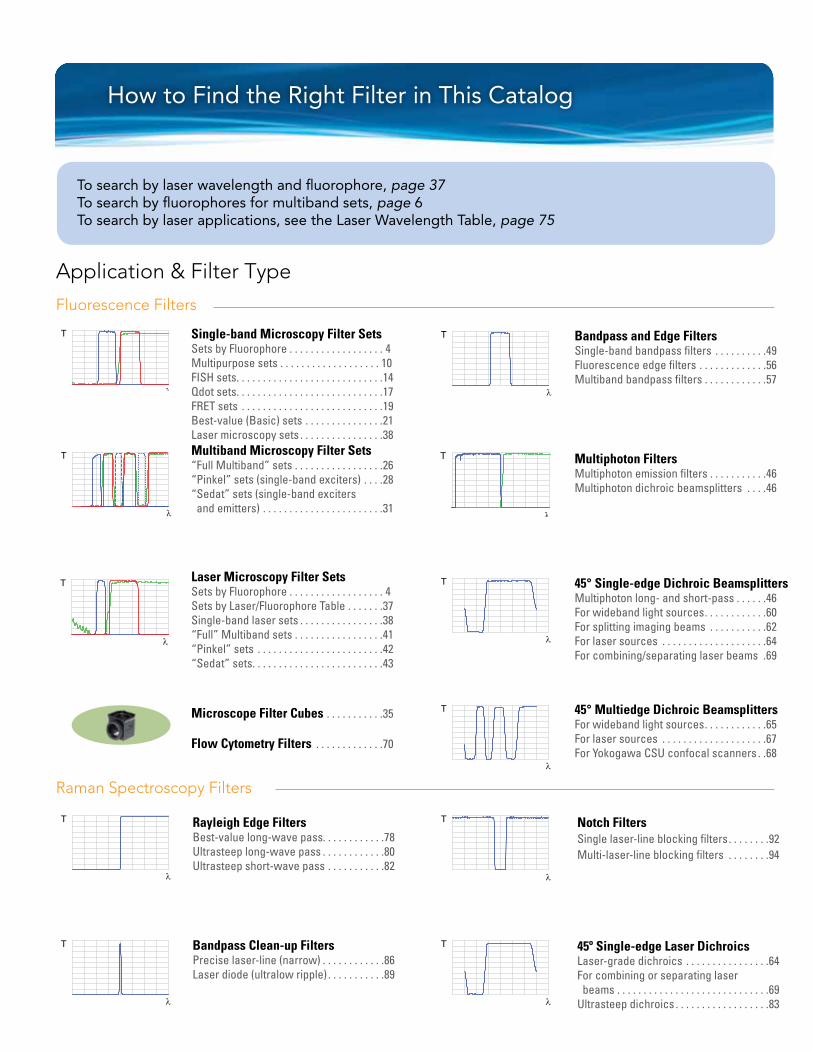
How to Find the Right Filter in This Catalog
Single-band Microscopy Filter SetsSets by Fluorophore . . . . . . . . . . . . . . . . . . 4Multipurpose sets . . . . . . . . . . . . . . . . . . . 10FISH sets. . . . . . . . . . . . . . . . . . . . . . . . . . . .14Qdot sets. . . . . . . . . . . . . . . . . . . . . . . . . . . .17FRET sets . . . . . . . . . . . . . . . . . . . . . . . . . . .19 Best-value (Basic) sets . . . . . . . . . . . . . . .21Laser microscopy sets . . . . . . . . . . . . . . . .38Multiband Microscopy Filter Sets“Full Multiband” sets . . . . . . . . . . . . . . . . .26“Pinkel” sets (single-band exciters) . . . .28“Sedat” sets (single-band exciters and emitters) . . . . . . . . . . . . . . . . . . . . . . .31
Laser Microscopy Filter SetsSets by Fluorophore . . . . . . . . . . . . . . . . . . 4 Sets by Laser/Fluorophore Table . . . . . . .37Single-band laser sets . . . . . . . . . . . . . . . .38“Full” Multiband sets . . . . . . . . . . . . . . . . .41“Pinkel” sets . . . . . . . . . . . . . . . . . . . . . . . .42“Sedat” sets. . . . . . . . . . . . . . . . . . . . . . . . .43
Microscope Filter Cubes . . . . . . . . . . .35
Flow Cytometry Filters . . . . . . . . . . . . .70
T
λ
T
λ
T
λ
T
λ
T
λ
Application & Filter Type
To search by laser wavelength and fluorophore, page 37To search by fluorophores for multiband sets, page 6To search by laser applications, see the Laser Wavelength Table, page 75
T
λ
T
λ
T
λ
T
λ
T
λ
T
λ
Bandpass and Edge FiltersSingle-band bandpass filters . . . . . . . . . .49Fluorescence edge filters . . . . . . . . . . . . .56Multiband bandpass filters . . . . . . . . . . . .57
Multiphoton FiltersMultiphoton emission filters . . . . . . . . . . .46Multiphoton dichroic beamsplitters . . . .46
45° Single-edge Dichroic BeamsplittersMultiphoton long- and short-pass . . . . . .46 For wideband light sources. . . . . . . . . . . .60For splitting imaging beams . . . . . . . . . . .62For laser sources . . . . . . . . . . . . . . . . . . . .64For combining/separating laser beams .69
45° Multiedge Dichroic BeamsplittersFor wideband light sources. . . . . . . . . . . .65For laser sources . . . . . . . . . . . . . . . . . . . .67For Yokogawa CSU confocal scanners . .68
Rayleigh Edge FiltersBest-value long-wave pass. . . . . . . . . . . .78 Ultrasteep long-wave pass . . . . . . . . . . . .80Ultrasteep short-wave pass . . . . . . . . . . .82
Bandpass Clean-up FiltersPrecise laser-line (narrow) . . . . . . . . . . . .86Laser diode (ultralow ripple) . . . . . . . . . . .89
Notch FiltersSingle laser-line blocking filters. . . . . . . .92Multi-laser-line blocking filters . . . . . . . .94
45º Single-edge Laser DichroicsLaser-grade dichroics . . . . . . . . . . . . . . . .64For combining or separating laser beams . . . . . . . . . . . . . . . . . . . . . . . . . . . . .69Ultrasteep dichroics . . . . . . . . . . . . . . . . . .83
Fluorescence Filters
Raman Spectroscopy Filters
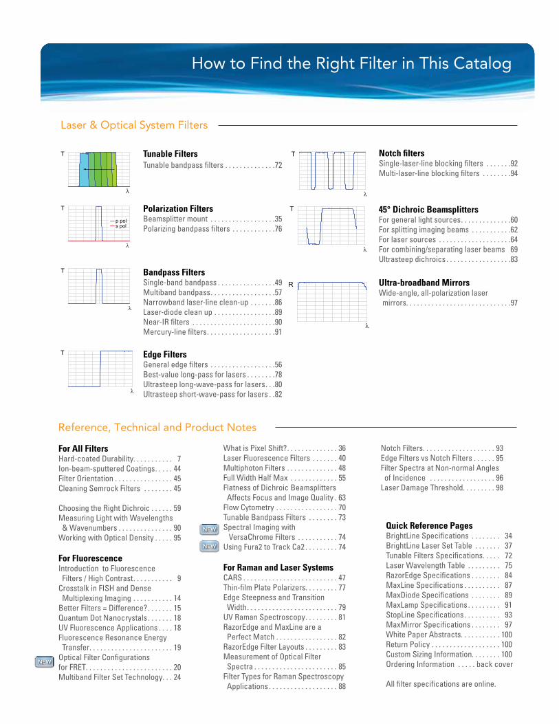
How to Find the Right Filter in This Catalog
Reference, Technical and Product Notes
For All FiltersHard-coated Durability. . . . . . . . . . . 7Ion-beam-sputtered Coatings. . . . . 44 Filter Orientation . . . . . . . . . . . . . . . . 45 Cleaning Semrock Filters . . . . . . . . 45
Choosing the Right Dichroic . . . . . . 59Measuring Light with Wavelengths & Wavenumbers . . . . . . . . . . . . . . . 90Working with Optical Density . . . . . 95
For FluorescenceIntroduction to Fluorescence Filters / High Contrast. . . . . . . . . . . 9Crosstalk in FISH and Dense Multiplexing Imaging . . . . . . . . . . . 14Better Filters = Difference?. . . . . . . 15Quantum Dot Nanocrystals . . . . . . . 18UV Fluorescence Applications . . . . 18Fluorescence Resonance Energy Transfer. . . . . . . . . . . . . . . . . . . . . . . 19Optical Filter Configurations for FRET. . . . . . . . . . . . . . . . . . . . . . . . 20Multiband Filter Set Technology. . . 24
What is Pixel Shift?. . . . . . . . . . . . . . 36Laser Fluorescence Filters . . . . . . . 40Multiphoton Filters . . . . . . . . . . . . . . 48Full Width Half Max . . . . . . . . . . . . . 55Flatness of Dichroic Beamsplitters Affects Focus and Image Quality . 63Flow Cytometry . . . . . . . . . . . . . . . . . 70Tunable Bandpass Filters . . . . . . . . 73Spectral Imaging with VersaChrome Filters . . . . . . . . . . . 74Using Fura2 to Track Ca2 . . . . . . . . . 74
For Raman and Laser Systems CARS . . . . . . . . . . . . . . . . . . . . . . . . . . 47Thin-film Plate Polarizers. . . . . . . . . 77Edge Steepness and Transition Width. . . . . . . . . . . . . . . . . . . . . . . . . 79UV Raman Spectroscopy. . . . . . . . . 81RazorEdge and MaxLine are a Perfect Match . . . . . . . . . . . . . . . . . 82RazorEdge Filter Layouts . . . . . . . . . 83Measurement of Optical Filter Spectra . . . . . . . . . . . . . . . . . . . . . . . 85 Filter Types for Raman Spectroscopy Applications . . . . . . . . . . . . . . . . . . . 88
Laser & Optical System Filters
T
λ
T
λ
T
λ
T
λ
R
λ
T
λ
Tunable FiltersTunable bandpass filters . . . . . . . . . . . . . .72
Polarization FiltersBeamsplitter mount . . . . . . . . . . . . . . . . . .35 Polarizing bandpass filters . . . . . . . . . . . .76
Bandpass FiltersSingle-band bandpass . . . . . . . . . . . . . . . .49Multiband bandpass. . . . . . . . . . . . . . . . . .57 Narrowband laser-line clean-up . . . . . . .86Laser-diode clean up . . . . . . . . . . . . . . . . .89Near-IR filters . . . . . . . . . . . . . . . . . . . . . . .90Mercury-line filters. . . . . . . . . . . . . . . . . . .91
Edge FiltersGeneral edge filters . . . . . . . . . . . . . . . . . .56Best-value long-pass for lasers . . . . . . . .78 Ultrasteep long-wave-pass for lasers. . .80Ultrasteep short-wave-pass for lasers . .82
Notch filtersSingle-laser-line blocking filters . . . . . . .92Multi-laser-line blocking filters . . . . . . . .94
45° Dichroic BeamsplittersFor general light sources. . . . . . . . . . . . . .60For splitting imaging beams . . . . . . . . . . .62For laser sources . . . . . . . . . . . . . . . . . . . .64For combining/separating laser beams 69Ultrasteep dichroics . . . . . . . . . . . . . . . . . .83
Ultra-broadband MirrorsWide-angle, all-polarization laser mirrors. . . . . . . . . . . . . . . . . . . . . . . . . . . . .97
T
λ
p pols pol
Quick Reference PagesBrightLine Specifications . . . . . . . . 34BrightLine Laser Set Table . . . . . . . 37Tunable Filters Specifications. . . . . 72Laser Wavelength Table . . . . . . . . . 75RazorEdge Specifications . . . . . . . . 84MaxLine Specifications . . . . . . . . . . 87MaxDiode Specifications . . . . . . . . 89MaxLamp Specifications . . . . . . . . . 91StopLine Specifications . . . . . . . . . . 93MaxMirror Specifications . . . . . . . . 97White Paper Abstracts. . . . . . . . . . . 100Return Policy . . . . . . . . . . . . . . . . . . . 100Custom Sizing Information. . . . . . . . 100Ordering Information . . . . . back cover
All filter specifications are online.
Notch Filters. . . . . . . . . . . . . . . . . . . . 93 Edge Filters vs Notch Filters . . . . . . 95Filter Spectra at Non-normal Angles of Incidence . . . . . . . . . . . . . . . . . . 96Laser Damage Threshold. . . . . . . . . 98
NEW
NEW
NEW

Superior Performance
The Standard in Optical Filters for Life Sciences, Lasers & Optical Systems
Semrock successfully combines the most sophisticated and modern ion-beam-sputtering deposition systems, renowned for their stability, with its own proprietary deposition control technology, unique predictive algorithms, process improve-ments, and volume manufacturing capability. The result is optical filters of unsurpassed performance that set the standard for the Biotech and Analytical Instrumentation industries. These filters are so exceptional that they are patented and award-winning. We never stop innovating.
Semrock’s no burn-out optical filters are all made with ion-beam sputtering and our exclusively single-substrate construction for the highest transmission on the market. And steeper edges, precise wavelength accuracy, and carefully optimized blocking mean better contrast and faster measurements – even at UV wavelengths.
300 320 4600
10
20
30
40
50
60
70
80
90
100
Tran
smis
sio
n (%
)
Wavelength (nm)
340 360 400 440380 420
Measured UVfilter spectrum
250 300 5000
10
20
30
40
50
60
70
80
90
100
Tran
smis
sio
n (%
)
Wavelength (nm)
350 400 450
Measured UVfilter spectrum
44
New Website - New Features!
Order directly online!
Easier to find New or Red Tag clearance items
Improved Sales Support
Expanded Technical Information
Volume Custom Filter Request Form
www.semrock.com [email protected] 1-866-SEMROCK
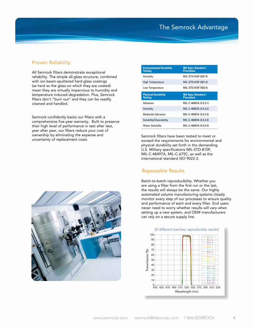
Proven Reliability
All Semrock filters demonstrate exceptional reliability. The simple all-glass structure, combined with ion-beam-sputtered hard glass coatings (as hard as the glass on which they are coated) mean they are virtually impervious to humidity and temperature induced degradation. Plus, Semrock filters don’t “burn out” and they can be readily cleaned and handled.
Semrock confidently backs our filters with a comprehensive five-year warranty. Built to preserve their high level of performance in test after test, year after year, our filters reduce your cost of ownership by eliminating the expense and uncertainty of replacement costs.
The Standard in Optical Filters for Life Sciences, Lasers & Optical Systems
55www.semrock.com [email protected] 1-866-SEMROCK
Repeatable Results
The Semrock Advantage
Batch-to-batch reproducibility. Whether you are using a filter from the first run or the last, the results will always be the same. Our highly automated volume manufacturing systems closely monitor every step of our processes to ensure quality and performance of each and every filter. End users never need to worry whether results will vary when setting up a new system, and OEM manufacturers can rely on a secure supply line.
0
10
20
30
40
50
60
70
80
90
100
Tran
smis
sio
n (%
)
Wavelength (nm)
20 different batches; reproducible results!
470450430 510 550 590 630490 530 570 610
Run 1Run 2Run 3Run 4Run 5Run 6Run 7Run 8Run 9Run 10Run 11Run 12Run 13Run 14Run 15Run 16Run 17Run 18
Run 20Run 19
Environmental Durability Testing
Mil Spec Standard / Procedure
Humidity MIL-STD-810F (507.4)
High Temperature MIL-STD-810F (501.4)
Low Temperature MIL-STD-810F (502.4)
Physical Durability Testing
Mil Spec Standard / Procedure
Adhesion MIL-C-48497A (4.5.3.1)
Humidity MIL-C-48497A (4.5.3.2)
Moderate Abrasion MIL-C-48497A (4.5.3.3)
Solubility/Cleanability MIL-C-48497A (4.5.4.2)
Water Solubility MIL-C-48497A (4.5.5.3)
Semrock filters have been tested to meet or exceed the requirements for environmental and physical durability set forth in the demanding U.S. Military specifications MIL-STD-810F, MIL-C-48497A, MIL-C-675C, as well as the international standard ISO 9022-2.

www.semrock.com [email protected] 1-866-SEMROCK
Laser Line
Laser Type
Prominent Applications Pg 76 Pg 80 Pg 86 Pg 89 Pg 92 Pg 78 Pg 64 Pg 69 Pg 97
224.3 HeAg gas Raman l
248.6 NeCu gas Raman l l
257.3 Doubled Ar-ion gas Raman l
266.0 Quadrupled DPSS Raman l l
325.0 HeCd gas Raman l l
355.0 Tripled DPSS Raman l l l
363.8 Ar-ion gas Raman l l l
~ 375 Diode Fluorescence (DAPI) l l l l
~ 405 Diode Fluorescence (DAPI) l l l l l l l
~ 440 Diode Fluorescence (CFP) l l l l
441.6 HeCd gas Raman, Fluorescence (CFP) l l l l l
457.9 Ar-ion gas Fluorescence (CFP) l l l l l
~ 470 Diode Fluorescence (GFP) l l l l
473.0 Doubled DPSSFluorescence (GFP), Raman l l l l l
488.0 Ar-ion gasRaman, Fluorescence (FITC, GFP) l l l l l l l
~ 488 Doubled OPS Fluorescence (FITC, GFP) l l l l l
491.0 Doubled DPSS Fluorescence (FITC, GFP) l l l l l
514.5 Ar-ion gas Raman, Fluorescence (YFP) l l l l l l l
515.0 Doubled DPSS Fluorescence (YFP) l l l l l
532.0 Doubled DPSS Raman, Fluorescence l l l l l l l l
543.5 HeNe gas Fluorescence (TRITC, Cy3) l l l
561.4 Doubled DPSSFluorescence (RFP, Texas Red®) l l l l l l l
568.2 Kr-ion gasFluorescence (RFP, Texas Red) l l l l l l
593.5 Doubled DPSSFluorescence (RFP, Texas Red) l l l l l
594.1 HeNe gasFluorescence (RFP, Texas Red) l l l l l
632.8 HeNe gas Raman, Fluorescence (Cy5) l l l l l l l l
~ 635 Diode Fluorescence (Cy5) l l l l l l
647.1 Kr-ion gas Fluorescence (Cy5) l l l l l l
664.0 Doubled DPSS Raman l l
671.0 Doubled DPSSRaman, Fluorescence (Cy5.5, Cy7) l l
780.0 EC diode Raman l l l l
~ 785 Diode Raman l l l
785.0 EC Diode Raman l l l l l l
~ 808 Diode DPSS pumping, Raman l l l l
830.0 EC diode Raman l l l
976.0 EC diode Raman l l l
980.0 EC diode Raman l l l
1047.1 DPSS Raman l l l
1064.0 DPSS Raman l l l l
1319.0 DPSS Raman l
Laser Wavelength Reference Table
Key: Diode = semiconductor diode laser EC diode = wavelength-stablized external-cavity diode laser DPSS = diode-pumped solid-state laser OPS = optically pumped semiconductor laser Doubled, Tripled, Quadrupled = harmonic frequency upconversion using nonlinear optics
Razor
Edge
® (LW
P)
Polariz
ation
Filte
rs
Max
Line®
Max
Diode™
StopLin
e®
Edge
Basic™
BrightL
ine®
La
ser D
ichro
ics
Max
Mirr
or®
Laser Waveleng
th Reference Tab
le
Lase
rMUX™
75
www.semrock.com [email protected] 1-866-SEMROCK
Every Semrock filter is hard-coated for durable performance.Five-year warranty.
Po
lari
zati
on
Filt
ers
76
Polarization Filters
Nominal Laser Wavelength
Wavelength Range for AOI = 45°± 0.5°
AOI Range for Nominal Laser Wavelength
OD 2 Avg. PolarizationBlocking Range[1]
OD 6 S-Pol Blocking Range
OD 6 P-PolBlocking Range Part Number Price
405 nm 400 – 410 nm 41° – 51° 300 – 332 nm490 – 1100 nm 320 – 516 nm 332 – 388 nm
422 – 490 nm PBP01-405/10-25x36 $795
532 nm 518 – 541 nm 38° – 52° 300 – 418 nm664 – 1100 nm 400 – 695 nm 418 – 502 nm
557 – 664 nm PBP01-529/23-25x36 $795
640 nm 628.5 – 650 nm 40.5° – 51° 300 – 511 nm795 – 1100 nm 488 – 840 nm 511 – 602 nm
675 – 795 nm PBP01-639/21-25x36 $795
1064 nm 1038 – 1081 nm 39° – 51° 300 – 851 nm1307 – 1750 nm 720 – 1393 nm 851 – 996 nm
1120 – 1307 nm PBP01-1059/43-25x36 $895
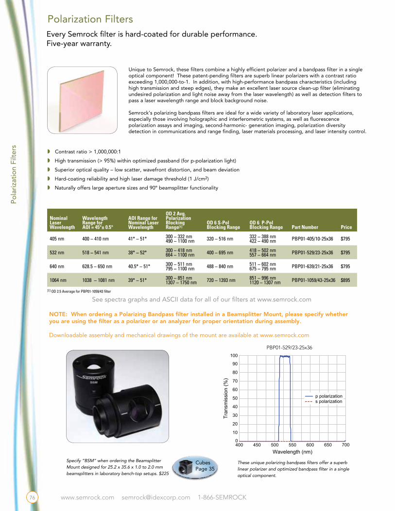
Unique to Semrock, these filters combine a highly efficient polarizer and a bandpass filter in a single optical component! These patent-pending filters are superb linear polarizers with a contrast ratio exceeding 1,000,000-to-1. In addition, with high-performance bandpass characteristics (including high transmission and steep edges), they make an excellent laser source clean-up filter (eliminating undesired polarization and light noise away from the laser wavelength) as well as detection filters to pass a laser wavelength range and block background noise.
Semrock’s polarizing bandpass filters are ideal for a wide variety of laboratory laser applications, especially those involving holographic and interferometric systems, as well as fluorescence polarization assays and imaging, second-harmonic- generation imaging, polarization diversity detection in communications and range finding, laser materials processing, and laser intensity control.
w Contrast ratio > 1,000,000:1
w High transmission (> 95%) within optimized passband (for p-polarization light)
w Superior optical quality – low scatter, wavefront distortion, and beam deviation
w Hard-coating reliability and high laser damage threshold (1 J/cm2)
w Naturally offers large aperture sizes and 90º beamsplitter functionality
See spectra graphs and ASCII data for all of our filters at www.semrock.com
Specify “BSM” when ordering the Beamsplitter Mount designed for 25.2 x 35.6 x 1.0 to 2.0 mm beamsplitters in laboratory bench-top setups. $225
These unique polarizing bandpass filters offer a superb linear polarizer and optimized bandpass filter in a single optical component.
450400 500 550 6000
10
20
30
40
50
60
70
80
90
100
Tran
smis
sion
(%)
Wavelength (nm)700650
s polarizationp polarization
NOTE: When ordering a Polarizing Bandpass filter installed in a Beamsplitter Mount, please specify whether you are using the filter as a polarizer or an analyzer for proper orientation during assembly.
Downloadable assembly and mechanical drawings of the mount are available at www.semrock.com
[1] OD 2.5 Average for PBP01-1059/43 filter
Cubes Page 35
PBP01-529/23-25x36
www.semrock.com [email protected] 1-866-SEMROCK
Polarization Filters
Property Value Comments
Guaranteed Transmission > 95% p-polarized light
Contrast 1,000,000:1 Ratio of transmission through two identical aligned polarizers to transmission through same pair of crossed polarizers
Blocking See table on page 76
Nominal Angle of Incidence 45° AOI tolerance (See table on page 76)
Laser Damage Threshold 1 J/cm2 @ 532 nm 10 ns pulse width P-pol (See page 98)
Substrate Material Ultra-low autofluorescence fused silica
Dimensions & Tolerance 25.2 mm x 35.6 mm x 2.0 mm ± 0.1 mm Mount option on page 35
Clear Aperture ≥ 85% Ellipitcal, for all optical specifications
Transmitted Wavefront Error < λ/4 RMS at λ = 633 nm Peak-to-valley error < 5 x RMS
Beam Deviation ≤ 10 arc seconds Measured per inch
Surface Quality 40-20 scratch-dig Measured within clear aperture
OrientationCoating (Text) towards from light For use as a polarizer
Coating (Text) away light For use as an analyzer
Common Specifications
Thin-film Plate Polarizers
A “polarizer” transmits a single state of polarization of light while absorbing, reflecting, or deviating light with the orthogo-nal state of polarization. Applications include fluorescence polarization assays and imaging, second-harmonic-generation imaging, polarization diversity detection in communications and rangefinding, and laser materials processing, to name a few. Polarizers are characterized by the “contrast ratio,” or the ratio of the transmission through a pair of identical aligned polar-izers to the transmission through the same pair of crossed polarizers. Contrast ratios typically vary from about 100:1 to as large as 100,000:1.
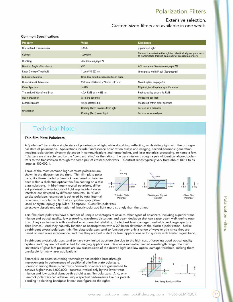
Three of the most common high-contrast polarizers are shown in the diagram on the right. Thin-film plate polar-izers, like those made by Semrock, are based on interfer-ence within a dielectric optical thin-film coating on a thin glass substrate. In birefringent crystal polarizers, differ-ent polarization orientations of light rays incident on an interface are deviated by different amounts. In “Glan” calcite polarizers, extinction is achieved by total internal reflection of s-polarized light at a crystal-air gap (Glan-laser) or crystal-epoxy gap (Glan-Thompson). Glass film polarizers selectively absorb one orientation of linearly polarized light more strongly than the other.
Thin-film plate polarizers have a number of unique advantages relative to other types of polarizers, including superior trans-mission and optical quality, low scattering, wavefront distortion, and beam deviation that can cause beam walk during rota-tion. They can be made with excellent environmental reliability, the highest laser damage thresholds, and large aperture sizes (inches). And they naturally function as beamsplitters with a 90º beam deviation of the blocked polarization. Unlike birefringent crystal polarizers, thin-film plate polarizers tend to function over only a range of wavelengths since they are based on multiwave interference, and thus they are best suited for laser applications or for systems with limited signal band.
Birefringent crystal polarizers tend to have very limited aperture size due to the high cost of growing good optical-quality crystals, and they are not well suited for imaging applications. Besides a somewhat limited wavelength range, the main limitations of glass film polarizers are low transmission of the desired light and low optical damage threshold, making them unsuitable for many laser applications.
Semrock’s ion beam sputtering technology has enabled breakthrough improvements in performance of traditional thin-film plate polarizers. Foremost among these is contrast – Semrock polarizers are guaranteed to achieve higher than 1,000,000:1 contrast, rivaled only by the lower-trans-mission and low optical damage-threshold glass film polarizers. And, only Semrock polarizers can achieve unique spectral performance like our patent-pending “polarizing bandpass filters” (see figure on the right).
s & p p onlys & p p only
Thin-film PlatePolarizer
Birefringent CrystalPolarizer
Polarizing Bandpass Filter
Glass FilmPolarizer
s only
s & pp only
s onlys & p
s & p
s & p p only
s only
Tps
λ
s & p p onlys & p p only
Thin-film PlatePolarizer
Birefringent CrystalPolarizer
Polarizing Bandpass Filter
Glass FilmPolarizer
s only
s & pp only
s onlys & p
s & p
s & p p only
s only
Tps
λ
Technical Note
Po
larization Filters
Extensive selection.Custom-sized filters are available in one week.
77
www.semrock.com [email protected] 1-866-SEMROCK
EdgeBasic™ Long Wave Pass Filters B
est-
valu
e E
dg
e Fi
lter
s
EdgeBasic long-wave-pass filters offer a superb combination of performance and value for applications in Raman spectroscopy and fluorescence imaging and measurements. This group of filters is ideal for specific Raman applications that do not require measuring the smallest possible Raman shifts, yet demand exceptional laser-line blocking and high transmission over a range of Raman lines.
Nominal Laser Wavelength
Laser Wavelength Range
Passband Part Number Priceλ short λ long405 nm 400.0 nm 410.0 nm 421.5 – 900.0 nm BLP01-405R-25 $325
458 nm 439.0 nm 457.9 nm 470.0 – 900.0 nm BLP01-458R-25 $325
488 nm 486.0 nm 491.0 nm 504.7 – 900.0 nm BLP01-488R-25 $325
515 nm 505.0 nm 515.0 nm 529.4 – 900.0 nm BLP01-514R-25 $325
532 nm 532.0 nm 532.0 nm 546.9 – 900.0 nm BLP01-532R-25 $325
561 nm 561.0 nm 568.0 nm 583.9 – 900.0 nm BLP01-561R-25 $325
594 nm 593.5 nm 594.1 nm 610.6 – 900.0 nm BLP01-594R-25 $325
635 nm 632.8 nm 642.0 nm 660.0 – 1200.0 nm BLP01-635R-25 $325
785 nm 780.0 nm 790.0 nm 812.1 – 1200.0 nm BLP01-785R-25 $325
w Deep laser-line blocking – for maximum laser rejection (OD > 6)
w Extended short-wavelength blocking – for high-fidelity fluorescence imaging
w High signal transmission – to detect the weakest signals (> 98% typical)
w Proven no burn-out durability – for lasting and reliable performance
w For the ultimate performance, upgrade to state-of-the-art RazorEdge® Raman filters (see page 80)
Property Value Comments
Edge Steepness (typical) 1.5% of λlong Measured from OD 6 to 50%
Blocking at Laser Wavelengths OD > 6 from 80% of λshort to λlongOD > 5 from 270 nm to 80% of λshort
OD = – log10 (transmission)
Transition Width < 2.5% of λlong From λlong to the 50% transmission wavelength
Guaranteed Transmission > 93% Averaged over the passband
Typical Transmission > 98% Averaged over the passband
Minimum Transmission > 90% Over the passband
Angle of Incidence 0.0° ± 2.0° Range for above optical specifications
Cone Half Angle < 5° Rays uniformly distributed about 0°
Angle Tuning Range – 0.3% of Laser Wavelength Wavelength “blue shift” increasing angle from 0° to 8°
Substrate Material Low-autofluorescence optical quality glass
Clear Aperture > 22 mm
Outer Diameter 25.0 + 0.0 / – 0.1 mm Black-anodized aluminum ring
Overall Thickness 3.5 ± 0.1 mm Black-anodized aluminum ring
Beam Deviation < 10 arc seconds
Surface Quality 60-40 scratch-dig
Filter Orientation Arrow on ring indicates preferred direction of propagation of light
78
Common Specifications
See spectra graphs and ASCII data for all of our filters at www.semrock.com
Every Semrock filter is hard-coated for durable performance.Five-year warranty.
www.semrock.com [email protected] 1-866-SEMROCK
Product Note
Edge Steepness and Transition Width
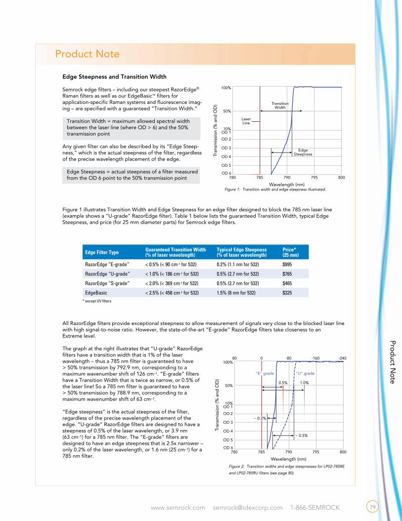
Semrock edge filters – including our steepest RazorEdge® Raman filters as well as our EdgeBasic™ filters for application-specific Raman systems and fluorescence imag-ing – are specified with a guaranteed “Transition Width.”
Transition Width = maximum allowed spectral width between the laser line (where OD > 6) and the 50% transmission point
Any given filter can also be described by its “Edge Steep-ness,” which is the actual steepness of the filter, regardless of the precise wavelength placement of the edge.
Edge Steepness = actual steepness of a filter measured from the OD 6 point to the 50% transmission point
Figure 1 illustrates Transition Width and Edge Steepness for an edge filter designed to block the 785 nm laser line (example shows a “U-grade” RazorEdge filter). Table 1 below lists the guaranteed Transition Width, typical Edge Steepness, and price (for 25 mm diameter parts) for Semrock edge filters.
All RazorEdge filters provide exceptional steepness to allow measurement of signals very close to the blocked laser line with high signal-to-noise ratio. However, the state-of-the-art “E-grade” RazorEdge filters take closeness to an Extreme level.
The graph at the right illustrates that “U-grade” RazorEdge filters have a transition width that is 1% of the laser wavelength – thus a 785 nm filter is guaranteed to have > 50% transmission by 792.9 nm, corresponding to a maximum wavenumber shift of 126 cm–1. “E-grade” filters have a Transition Width that is twice as narrow, or 0.5% of the laser line! So a 785 nm filter is guaranteed to have > 50% transmission by 788.9 nm, corresponding to a maximum wavenumber shift of 63 cm–1.
“Edge steepness” is the actual steepness of the filter, regardless of the precise wavelength placement of the edge. “U-grade” RazorEdge filters are designed to have a steepness of 0.5% of the laser wavelength, or 3.9 nm (63 cm–1) for a 785 nm filter. The “E-grade” filters are designed to have an edge steepness that is 2.5x narrower – only 0.2% of the laser wavelength, or 1.6 nm (25 cm–1) for a 785 nm filter.
Product N
ote
780 790785 795 800OD 6
OD 5
OD 4
OD 3
OD 2
OD 110%
50%
TransitionWidth
LaserLine
EdgeSteepness
100%
Tran
smis
sio
n (%
and
OD
)
Wavelength (nm)
Edge Filter Type Guaranteed Transition Width(% of laser wavelength)
Typical Edge Steepness(% of laser wavelength)
Price* (25 mm)
RazorEdge “E-grade” < 0.5% (< 90 cm-1 for 532) 0.2% (1.1 nm for 532) $995
RazorEdge “U-grade” < 1.0% (< 186 cm-1 for 532) 0.5% (2.7 nm for 532) $765
RazorEdge “S-grade” < 2.0% (< 369 cm-1 for 532) 0.5% (2.7 nm for 532) $465
EdgeBasic < 2.5% (< 458 cm-1 for 532) 1.5% (8 nm for 532) $325* except UV filters
Figure 1: Transition width and edge steepness illustrated.
780 790785 795 800
80 -800 -160 -240
OD 6
OD 5
OD 4
OD 3
OD 2
OD 110%
50%
~ 0.5%
0.5% 1.0%
100%
Tran
smis
sio
n (%
and
OD
)
Wavelength (nm)
Wavenumber Shift from 785 nm (cm–1)
~ 0.2%
“E” grade “U” grade
Figure 2: Transition widths and edge steepnesses for LP02-785RE
and LP02-785RU filters (see page 80).
79

www.semrock.com [email protected] 1-866-SEMROCK
Ram
an E
dg
e Fi
lter
s
Every Semrock filter is hard-coated for durable performance.Five-year warranty.
RazorEdge® Long Wave Pass Raman Edge Filters
w The steepest edge filters on the market − RazorEdge E-grade filters (See just how steep on page 79)
w For long-wave-pass edge filtersfor normal incidence, see below
w Forshort-wave-pass edge filtersfor normal incidence, see page 82
w Forultrasteep 45° beamsplitters,see page 83
w For a suitably matched laser-line filter,see page 86
Semrock stocks an unsurpassed selection of the highest performance edge filters available for Raman Spectroscopy, with edge wave-lengths from 224 to 1319 nm. Now you can see the weakest signals closer to the laser line than you ever have before. With their deep laser-line blocking, ultra-wide and low-ripple passbands, proven hard-coating reliability, and high laser damage threshold, they offer performance that lasts. U.S. Patent No. 7,068,430 and pending.
[1] See pages 79 and 90 for more informationon transition width and wavenumbers
Laser Line
Transition Width [1] Passband Part Number Price
224.3 nm < 1920 cm–1 235.0-505.9 nm LP02-224R-25 $995
248.6 nm < 805 cm–1 261.0-560.8 nm LP02-248RS-25 $995
257.3 nm < 385 cm–1 < 762 cm–1
263.0-580.4 nm 265.5-580.4 nm
LP02-257RU-25 LP02-257RS-25
$995 $545
266.0 nm < 372 cm–1 < 737 cm–1
272.4-600.0 nm 275.0-600.0 nm
LP02-266RU-25 LP02-266RS-25
$995 $545
325.0 nm < 305 cm–1
< 603 cm–1329.2-733.1 nm 332.5-733.1 nm
LP03-325RU-25 LP03-325RS-25
$765 $465
355.0 nm < 140 cm–1
< 279 cm–1
< 552 cm–1
357.3-800.8 nm359.6-800.8 nm 363.2-800.8 nm
LP02-355RE-25LP02-355RU-25 LP02-355RS-25
$995$765 $465
363.8 nm < 272 cm–1
< 539 cm–1368.5-820.6 nm 372.2-820.6 nm
LP02-364RU-25 LP02-364RS-25
$765 $465
441.6 nm < 224 cm–1
< 444 cm–1447.3-996.1 nm 451.8-996.1 nm
LP02-442RU-25 LP02-442RS-25
$765 $465
457.9 nm < 216 cm–1
< 428 cm–1463.9-668.4 nm 468.4-668.4 nm
LP02-458RU-25 LP02-458RS-25
$765 $465
473.0 nm < 209 cm–1
< 415 cm–1479.1-1066.9 nm 483.9-1066.9 nm
LP02-473RU-25 LP02-473RS-25
$765 $465
488.0 nm < 102 cm–1
< 203 cm–1
< 402 cm–1
491.2-1100.8 nm 494.3-1100.8 nm 499.2-1100.8 nm
LP02-488RE-25LP02-488RU-25 LP02-488RS-25
$995 $765 $465
514.5 nm < 97 cm–1
< 192 cm–1
< 381 cm–1
517.8-1160.5 nm 521.2-1160.5 nm 526.3-1160.5 nm
LP02-514RE-25 LP02-514RU-25 LP02-514RS-25
$995 $765 $465
532.0 nm < 90 cm–1
< 186 cm–1
< 369 cm–1
535.4-1200.0 nm 538.9-1200.0 nm 544.2-1200.0 nm
LP03-532RE-25LP03-532RU-25 LP03-532RS-25
$995$765 $465
561.4 nm < 176 cm–1
< 349 cm–1568.7-1266.3 nm 574.0-1266.3 nm
LP02-561RU-25LP02-561RS-25
$765$465
568.2 nm < 174 cm–1
< 345 cm–1575.6-1281.7 nm 581.3-1281.7 nm
LP02-568RU-25 LP02-568RS-25
$765 $465
632.8 nm < 79 cm–1
< 156 cm–1
< 310 cm–1
636.9-1427.4 nm 641.0-1427.4 nm 647.4-1427.4 nm
LP02-633RE-25 LP02-633RU-25 LP02-633RS-25
$995 $765 $465
25 mm Diameter
Laser Line
Transition Width [1] Passband Part Number Price
664.0 nm < 149 cm–1
< 295 cm–1672.6-1497.7 nm 679.3-1497.7 nm
LP02-664RU-25 LP02-664RS-25
$765 $465
780.0 nm < 127 cm–1
< 251 cm–1790.1-1759.4 nm 797.9-1759.4 nm
LP02-780RU-25 LP02-780RS-25
$765 $465
785.0 nm < 63 cm–1
< 126 cm–1
< 250 cm–1
790.1-1770.7 nm 795.2-1770.7 nm 803.1-1770.7 nm
LP02-785RE-25LP02-785RU-25 LP02-785RS-25
$965$765 $465
808.0 nm < 123 cm–1
< 243 cm–1818.5-1822.6 nm 826.6-1822.6 nm
LP02-808RU-25 LP02-808RS-25
$765 $465
830.0 nm < 119 cm–1
< 236 cm–1840.8-1872.2 nm 849.1-1872.2 nm
LP02-830RU-25 LP02-830RS-25
$765 $465
980.0 nm < 101 cm–1
< 200 cm–1992.7-2000.0 nm 1002.5-2000.0 nm
LP02-980RU-25 LP02-980RS-25
$765 $465
1064.0 nm < 93 cm–1
< 184 cm–11077.8-2000.0 nm 1088.5-2000.0 nm
LP02-1064RU-25 LP02-1064RS-25
$765 $465
1319.0 nm < 75 cm–1
< 149 cm–11336.1-2000.0 nm 1349.3-2000.0 nm
LP02-1319RU-25LP02-1319RS-25
$765$465
The spectral response of an S-grade filter is located anywhere between the red and green lines below. The spectral response of a U-grade filter is located anywhere between the red and blue lines below.
0%
50%
100%
530 532 534 536 538 540 542 544 546 548 550
Laser Line
U-grade Most Blueshifted
U-grade Most Redshifted
S-grade Most Redshifted
NEW
80
www.semrock.com [email protected] 1-866-SEMROCK
Technical Note
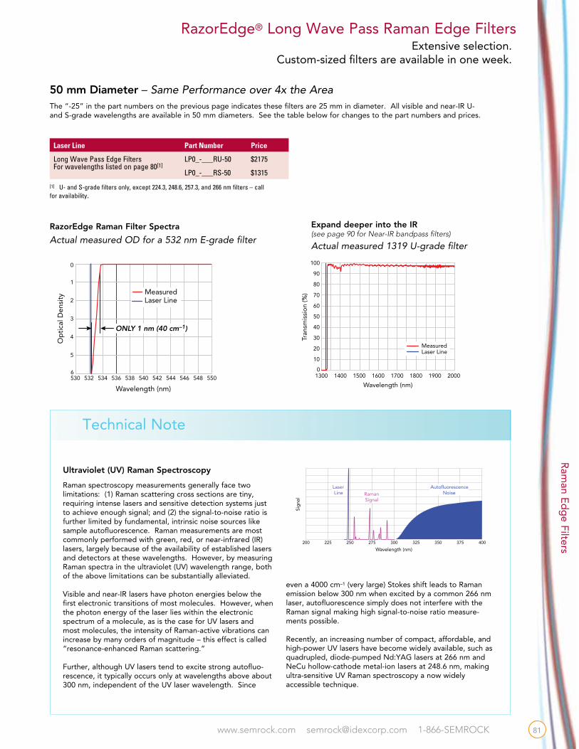
50 mm Diameter – Same Performance over 4x the Area
[1] U- and S-grade filters only, except 224.3, 248.6, 257.3, and 266 nm filters – call for availability.
The “-25” in the part numbers on the previous page indicates these filters are 25 mm in diameter. All visible and near-IR U- and S-grade wavelengths are available in 50 mm diameters. See the table below for changes to the part numbers and prices.
Laser Line Part Number Price
Long Wave Pass Edge FiltersFor wavelengths listed on page 80[1]
LP0_-___RU-50 $2175
LP0_-___RS-50 $1315
RazorEdge® Long Wave Pass Raman Edge Filters
RazorEdge Raman Filter Spectra
Ultraviolet (UV) Raman Spectroscopy
Raman spectroscopy measurements generally face two limitations: (1) Raman scattering cross sections are tiny, requiring intense lasers and sensitive detection systems just to achieve enough signal; and (2) the signal-to-noise ratio is further limited by fundamental, intrinsic noise sources like sample autofluorescence. Raman measurements are most commonly performed with green, red, or near-infrared (IR) lasers, largely because of the availability of established lasers and detectors at these wavelengths. However, by measuring Raman spectra in the ultraviolet (UV) wavelength range, both of the above limitations can be substantially alleviated.
Visible and near-IR lasers have photon energies below the first electronic transitions of most molecules. However, when the photon energy of the laser lies within the electronic spectrum of a molecule, as is the case for UV lasers and most molecules, the intensity of Raman-active vibrations can increase by many orders of magnitude – this effect is called “resonance-enhanced Raman scattering.”
Further, although UV lasers tend to excite strong autofluo-rescence, it typically occurs only at wavelengths above about 300 nm, independent of the UV laser wavelength. Since
even a 4000 cm–1 (very large) Stokes shift leads to Raman emission below 300 nm when excited by a common 266 nm laser, autofluorescence simply does not interfere with the Raman signal making high signal-to-noise ratio measure-ments possible.
Recently, an increasing number of compact, affordable, and high-power UV lasers have become widely available, such as quadrupled, diode-pumped Nd:YAG lasers at 266 nm and NeCu hollow-cathode metal-ion lasers at 248.6 nm, making ultra-sensitive UV Raman spectroscopy a now widely accessible technique.
Sig
nal
Wavelength (nm)200 225 250 275 300 325 350 375 400
LaserLine Raman
Signal
AutofluorescenceNoise
530 538534 546536532 542540 548544 5506
5
4
3
2
0
1
Op
tica
l Den
sity
Wavelength (nm)
ONLY 1 nm (40 cm–1)
Measured
530 538534 546536532 542540 548544 5506
5
4
3
2
0
1
Op
tica
l Den
sity
Wavelength (nm)
Steepest Edge Filters
ONLY 1 nm (40 cm–1)
Real Data!
RazorEdge® 532 nm filter
Laser Line
Actual measured OD for a 532 nm E-grade filter
Expand deeper into the IR(see page 90 for Near-IR bandpass filters)
Actual measured 1319 U-grade filter
1300 1400 18000
10
20
30
40
50
60
70
80
90
100
Tran
smis
sio
n (%
)
Wavelength (nm)1600 1700
Laser Line Measured
1500 1900 2000
Ram
an Ed
ge Filters
Extensive selection. Custom-sized filters are available in one week.
81
www.semrock.com [email protected] 1-866-SEMROCK
Ram
an E
dg
e Fi
lter
s
Every Semrock filter is hard-coated for durable performance.Five-year warranty.
RazorEdge® Short Wave Pass Raman Edge Filters
400 550500450 600 650 700 7500
10
20
30
40
50
60
70
80
90
100
Tran
smis
sio
n (%
)
Wavelength (nm)
Laser Line Measured
Actual measured data from a 632.8 nm RazorEdge filter
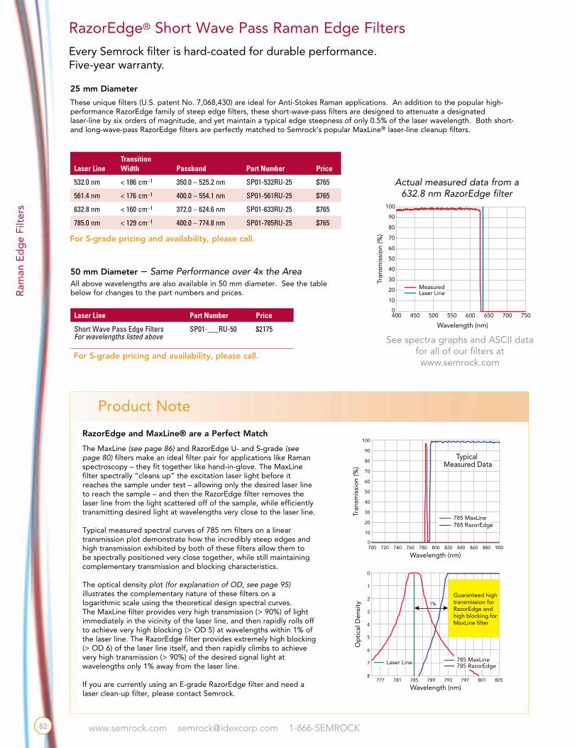
These unique filters (U.S. patent No. 7,068,430) are ideal for Anti-Stokes Raman applications. An addition to the popular high-performance RazorEdge family of steep edge filters, these short-wave-pass filters are designed to attenuate a designated laser-line by six orders of magnitude, and yet maintain a typical edge steepness of only 0.5% of the laser wavelength. Both short- and long-wave-pass RazorEdge filters are perfectly matched to Semrock’s popular MaxLine® laser-line cleanup filters.
25 mm Diameter
50 mm Diameter – Same Performance over 4x the AreaAll above wavelengths are also available in 50 mm diameter. See the table below for changes to the part numbers and prices.
Laser LineTransition Width Passband Part Number Price
532.0 nm < 186 cm–1 350.0 – 525.2 nm SP01-532RU-25 $765
561.4 nm < 176 cm–1 400.0 – 554.1 nm SP01-561RU-25 $765
632.8 nm < 160 cm–1 372.0 – 624.6 nm SP01-633RU-25 $765
785.0 nm < 129 cm–1 400.0 – 774.8 nm SP01-785RU-25 $765
Laser Line Part Number Price
Short Wave Pass Edge FiltersFor wavelengths listed above
SP01-___RU-50 $2175
RazorEdge and MaxLine® are a Perfect Match
The MaxLine (see page 86) and RazorEdge U- and S-grade (see page 80) filters make an ideal filter pair for applications like Raman spectroscopy – they fit together like hand-in-glove. The MaxLine filter spectrally “cleans up” the excitation laser light before it reaches the sample under test – allowing only the desired laser line to reach the sample – and then the RazorEdge filter removes the laser line from the light scattered off of the sample, while efficiently transmitting desired light at wavelengths very close to the laser line.
Typical measured spectral curves of 785 nm filters on a linear transmission plot demonstrate how the incredibly steep edges and high transmission exhibited by both of these filters allow them to be spectrally positioned very close together, while still maintaining complementary transmission and blocking characteristics.
The optical density plot (for explanation of OD, see page 95) illustrates the complementary nature of these filters on a logarithmic scale using the theoretical design spectral curves. The MaxLine filter provides very high transmission (> 90%) of light immediately in the vicinity of the laser line, and then rapidly rolls off to achieve very high blocking (> OD 5) at wavelengths within 1% of the laser line. The RazorEdge filter provides extremely high blocking (> OD 6) of the laser line itself, and then rapidly climbs to achieve very high transmission (> 90%) of the desired signal light at wavelengths only 1% away from the laser line.
If you are currently using an E-grade RazorEdge filter and need a laser clean-up filter, please contact Semrock.
Tran
smis
sio
n (%
)
Wavelength (nm)700 720 740 760 780 800 820 840 860 880 9000
10
20
30
40
50
60
70
80
90
100
785 RazorEdge 785 MaxLine
777 781 785 789 793 797 801 8058
7
6
5
4
3
2
1
0
Op
tica
l Den
sity
Wavelength (nm)
Laser Line
Guaranteed hightransmission forRazorEdge andhigh blocking forMaxLine filter
785 RazorEdge785 MaxLine
1%
Typical Measured Data
82
See spectra graphs and ASCII data for all of our filters at www.semrock.com
Product Note
For S-grade pricing and availability, please call.
For S-grade pricing and availability, please call.
www.semrock.com [email protected] 1-866-SEMROCK
RazorEdge Dichroic™ Beamsplitters
Laser LineTransition Width Passband
25 mm Mounted Part Number Price
Unmounted Part Number Price
488.0 nm < 203 cm–1
< 402 cm–1494.3 - 756.4 nm 499.2 - 756.4 nm
LPD01-488RU-25 LPD01-488RS-25
$545 $375
LPD01-488RU-25x36x1.1 LPD01-488RS-25x36x1.1
$765 $465
514.5 nm < 192 cm–1 < 381 cm–1
521.2 - 797.5 nm526.3 - 797.5 nm
LPD01-514RU-25LPD01-514RS-25
$545 $375
LPD01-514RU-25x36x1.1 LPD01-514RS-25x36x1.1
$765 $465
532.0 nm < 186 cm–1
< 369 cm–1538.9 - 824.8 nm 544.2 - 824.8 nm
LPD01-532RU-25 LPD01-532RS-25
$545 $375
LPD01-532RU-25x36x1.1 LPD01-532RS-25x36x1.1
$765 $465
632.8 nm < 156 cm–1
< 310 cm–1641.0 - 980.8 nm 647.4 - 980.8 nm
LPD01-633RU-25 LPD01-633RS-25
$545 $375
LPD01-633RU-25x36x1.1 LPD01-633RS-25x36x1.1
$765 $465
785.0 nm < 126 cm–1
< 250 cm–1795.2 -1213.8 nm 803.1 - 1213.8 nm
LPD01-785RU-25 LPD01-785RS-25
$545 $375
LPD01-785RU-25x36x1.1 LPD01-785RS-25x36x1.1
$765 $465
830.0 nm < 119 cm–1
< 236 cm–1840.8 - 1286.5 nm849.1 - 1286.5 nm
LPD01-830RU-25LPD01-830RS-25
$545 $375
LPD01-830RU-25x36x1.1 LPD01-830RS-25x36x1.1
$765 $465
1064.0 mm < 93 cm–1
< 184 cm–11077.8 - 1650.8 nm 1088.5 - 1650.8 nm
LPD01-1064RU-25 LPD01-1064RS-25
$545 $375
LPD01-1064RU-25x36x1.1 LPD01-1064RS-25x36x1.1
$765 $465
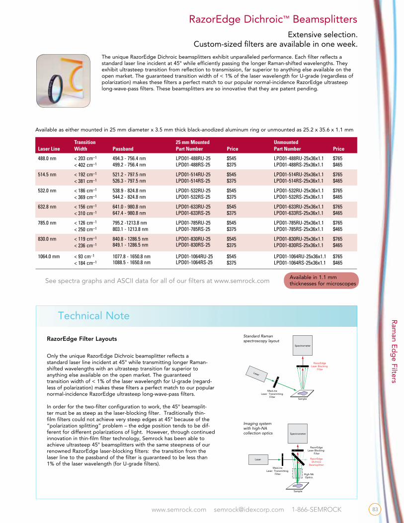
Available as either mounted in 25 mm diameter x 3.5 mm thick black-anodized aluminum ring or unmounted as 25.2 x 35.6 x 1.1 mm
The unique RazorEdge Dichroic beamsplitters exhibit unparalleled performance. Each filter reflects a standard laser line incident at 45° while efficiently passing the longer Raman-shifted wavelengths. They exhibit ultrasteep transition from reflection to transmission, far superior to anything else available on the open market. The guaranteed transition width of < 1% of the laser wavelength for U-grade (regardless of polarization) makes these filters a perfect match to our popular normal-incidence RazorEdge ultrasteep long-wave-pass filters. These beamsplitters are so innovative that they are patent pending.
RazorEdge Filter Layouts
Only the unique RazorEdge Dichroic beamsplitter reflects astandard laser line incident at 45° while transmitting longer Raman-shifted wavelengths with an ultrasteep transition far superior to anything else available on the open market. The guaranteed transition width of < 1% of the laser wavelength for U-grade (regard-less of polarization) makes these filters a perfect match to our popular normal-incidence RazorEdge ultrasteep long-wave-pass filters.
In order for the two-filter configuration to work, the 45° beamsplit-ter must be as steep as the laser-blocking filter. Traditionally thin-film filters could not achieve very steep edges at 45° because of the “polarization splitting” problem – the edge position tends to be dif-ferent for different polarizations of light. However, through continued innovation in thin-film filter technology, Semrock has been able to achieve ultrasteep 45° beamsplitters with the same steepness of our renowned RazorEdge laser-blocking filters: the transition from the laser line to the passband of the filter is guaranteed to be less than 1% of the laser wavelength (for U-grade filters).
Laser
Spectrometer
Sample
RazorEdgeLaser Blocking
Filter
MaxLineLaser Transmitting
Filter
Spectrometer
Laser RazorEdgeDichroic
Beamsplitter
RazorEdgeLaser Blocking
Filter
Sample
High-NAOptics
MaxLineLaser Transmitting
Filter
Standard Raman spectroscopy layout
Laser
Spectrometer
Sample
RazorEdgeLaser Blocking
Filter
MaxLineLaser Transmitting
Filter
Spectrometer
Laser RazorEdgeDichroic
Beamsplitter
RazorEdgeLaser Blocking
Filter
Sample
High-NAOptics
MaxLineLaser Transmitting
Filter
Imaging system with high-NA collection optics
83
See spectra graphs and ASCII data for all of our filters at www.semrock.com
Technical Note
Available in 1.1 mm thicknesses for microscopes
Ram
an Ed
ge Filters
Extensive selection. Custom-sized filters are available in one week.

www.semrock.com [email protected] 1-866-SEMROCK
Ram
an E
dg
e Fi
lter
s
Dichroic Beamsplitter Specifications
RazorEdge® Common Specifications
[1] For small angles (in degrees), the wavelength shift near the laser wavelength is Dl (nm) = – 5.0 x 10⁻⁵ x lL x q2 and the wavenumber shift is D(wavenumbers) (cm–1) = 500 x q2 / lL, where lL (in nm) is the laser wavelength. See Wavenumbers Techincal Note on page 90.
RazorEdge SpecificationsProperties apply to all long-wave-pass and short-wave-pass edge filters unless otherwise noted
Property Specification Comment
Edge Steepness (typical)
“E-grade” 0.2% of laser wavelength Measured from OD 6 to 50%; Up to 0.8% for 248-300 nm filters and 3.3% for 224 nm filter“U- & S-grades” 0.5% of laser wavelength
Blocking at Laser Wavelength > 6 OD OD = – log10 (transmission)
Transition Width
“E-grade” < 0.5% of laser wavelengthMeasured from laser wavelength to 50% transmission wavelength; < 4.5% for 224 nm filter“U-grade” < 1% of laser wavelength
“S-grade” < 2% of laser wavelength
Guaranteed Passband Transmission > 93% Except > 90% for 224 - 325 nm filters; Averaged over the Passband (Passband wavelengths on page 80 for LWP and page 82 for SWP filters)Typical Passband Transmission > 98%
Angle of Incidence 0.0° ± 2.0° Range for above optical specifications
Cone Half Angle < 5° Rays uniformly distributed about 0°
Angle Tuning Range [1] – 0.3% of Laser Wavelength (-1.6 nm or + 60 cm-1 for 532 nm) Wavelength “blue shift” attained by increasing angle from 0° to 8°
Laser Damage Threshold 0.5 J/cm2 @ 266 nm 1 J/cm2 @ 532 nm
10 ns pulse widthTested for 266 and 532 nm filters only (see page 98)
Clear Aperture > 22 mm (or > 45 mm)
Outer Diameter 25.0 + 0.0 / – 0.1 mm (or 50.0 + 0.0 /-0.1 nm) Black-anodized aluminum ring
Overall Thickness 3.5 ± 0.1 mm Black-anodized aluminum ring (thickness measured unmounted)
Beam Deviation < 10 arc seconds
Property Specification Comment
Edge Steepness (typical)0.5% of laser wavelength(2.5 nm or 90 cm-1 for 532 nm filter)
Measured from 5% to 50% transmission for light with average polarization
Transition Width“U-grade” < 1% of laser wavelength Measured from laser wavelength to 50% transmission wavelength for light with
average polarization“S-grade” < 2% of laser wavelength
Reflection at Laser Wavelength > 98% (s-polarization)> 90% (p-polarization)
Average Passband Transmission > 93% Averaged over the Passband (Passband wavelengths detailed on page 83)
Dependence of Wavelength on Angle of Incidence (Edge Shift) 0.35% / degree Linear relationship valid between about 40° & 50°
Cone Half Angle (for non-collimated light) < 0.5° Rays uniformly distributed and centered at 45°
Size of Round Dichroics
Clear Aperture ≥ 22 mm
Outer Diameter 25.0 + 0.0 / – 0.1 mm Black-anodized aluminum ring
Overall Thickness 3.5 ± 0.1 mm Black-anodized aluminum ring
Size of Rectangular Dichroics
Clear Aperture > 80% Elliptical
Size 25.2 mm x 35.6 mm ± 0.1 mm
Unmounted Thickness 1.05 ± 0.05 mm
Wedge Angle < 20 arc seconds
Flatness Reflection of a collimated, gaussian laser beam with waist diameter up to 3 mm causes less than one Rayleigh Range of focal shift after a focusing lens.
Property Specification Comment
Coating Type “Hard” ion-beam-sputtered
Reliability and Durability Ion-beam-sputtered, hard-coated technology with epoxy-free, single-substrate construction for unrivaled filter life. RazorEdge filters are rigorously tested and proven to MIL-STD-810F and MIL-C-48497A environmental standards.
Transmitted Wavefront Error < λ/ 4 RMS at λ = 633 nm Peak-to-valley error <5 x RMS measured within clear aperture
Surface Quality 60-40 scratch-dig
Temperature Dependence < 5 ppm / °C
Substrate Material Ultra-low autofluorescence fused silica (NBK7 or equivalent for LP01 filters)
Filter Orientation For mounted filters, arrow on ring indicates preferred direction of propagation of transmitted light. For rectangular dichroics, reflective coating side should face toward light source and sample.
General Specifications (all RazorEdge filters)
84

www.semrock.com [email protected] 1-866-SEMROCK
Measurement of Optical Filter Spectra
Due to limitations of standard metrology techniques, the measured spectral characteristics of thin-film interference filters are frequently not determined accurately, especially when there are steep and deep edges. The actual blocking provided by an optical filter is determined not only by its designed spectrum, but also by physical imperfections of the filter, such as pinholes generated during the thin-film coating process, dirt and other surface defects, or flaws in the filter mounting. Generally commercially available spectrophotometers are used to measure the transmission and OD spectral performance of optical filters. However, these instruments can have significant limitations when the optical filters have high edge steepness and/or very deep blocking.
As a result of these limitations, three main discrepancies appear between an actual filter spectrum and its measured representation (see Fig. 1). The first discrepancy is the “rounding” of sharp spectral features. This effect results from the non-zero bandwidth of the spectrophotometer probe beam. The second measurement discrepancy arises from limited sensitivity of the spectrophotometer. The third discrepancy is unique to measurements of very steep transitions from high blocking to high transmission, and is referred to as a “sideband measurement artifact.” This artifact arises from the non-monochromatic probe beam that also has weak sidebands at wavelengths outside of its bandwidth.
Semrock utilizes different measurement approaches to evaluate filter spectra. As an example, Figure 2 shows five measured spectra of the steep edge of an “E-grade” RazorEdge® filter that is guaranteed to block a laser line at 532 nm with OD > 6 and transition to high transmission within 0.5% of the laser wavelength (by 534.7 nm). The measured spectra are overlaid on the design spectrum of the filter (blue line). As observed in this figure, choice of a particular measurement instrument and technique greatly influences the measured spectrum of a filter. Measurement method “A” in this graph is from a custom-built spectrophotometer. This measurement uses instrument settings – such as short detector integration time and low resolution – that are optimized for very rapid data collection from a large number of sample filters during thin-film filter manufacturing process. However this method has poor sensitivity and resolution. Measurement method “B” uses a standard commercial spectrophotometer (Perkin Elmer Lambda 900 series). All of the discrepancies between the actual filter spectrum and the measured spectrum as noted above are apparent in this measurement. Measurement methods “C” and “D” utilize the same custom-built spectrophotometer from method “A.” The basic principle of operation of this spectrophotometer is shown in Fig. 3. This instrument uses a low-noise CMOS camera (i.e., detector array) capable of measuring a wide range of wavelengths simultaneously. Measurement method “C” uses instrument settings (primarily integration time and resolution) designed to provide enhanced measurement of the steep and deep edge. However, the “sideband measurement artifact” is still apparent. Measurement method “D” is a modification of method “C” that applies additional filtering to remove this artifact. Method “E” shows the results of a very precise measurement made with a carefully filtered 532 nm laser and angle tuning of the filter itself. Experimentally acquired transmission vs. angle data is converted into transmission vs. wavelength results, using a theoretical model. Clearly, this measurement method comes closest to the actual design curve; however it is not as suitable for quality assurance of large volumes of filters.
In summary, it is important to understand the measurement techniques used to generate optical filter spectra, as these techniques are not perfect. Use of the appropriate measurement approach for a given filter or application can reduce errors as well as over-design of experiments and systems that use filters, thus optimizing performance, results, and even filter cost. For additional information on this topic visit our website: www.semrock.com
Technical No
te
Technical Note
Figure 1: Measurement artifacts observed using a commmercial spectrophotometer.
Figure 2: Design and measurement spectra of the same filter (specified in Fig. 1) using different measurement approaches as explained in the text.
double monochromator
sample(filter)
filter wheel
broadband light
camera
Figure 3: A custom-built spectrophotom-eter that enables faster and more accurate measurements
85

www.semrock.com [email protected] 1-866-SEMROCK
w Highest laser-line transmission – stop wasting expensive laser light
w Steepest edges – perfect match to RazorEdge® U-grade filters (see page 80)
w Ideal complement to StopLine® deep notch filters for fluorescence and other applications (see page 92)
w Hard dielectric coatings for proven reliability and durability
w For diode lasers, use our MaxDiode™ Laser Clean-up filters (see page 89)
Semrock MaxLine Laser-line Filters have an unprecedented high transmission exceeding 90% at the laser line, while rapidly rolling off to an optical density (OD) > 5 at wavelengths differing by only 1% from the laser wavelength, and OD > 6 at wavelengths differing by only 1.5% from the laser wavelength. U.S. patent No. 7,119,960.
MaxLine® Laser-line Filters
735 745 755 765 775 785 795 805 815 825 8350
10
20
30
40
50
60
70
80
90
100
Measured Design
Tran
smis
sio
n (%
)
Wavelength (nm)
Measured Design
Instrument Noise Limit
735 745 755 765 775 785 795 805 815 825 8356
5
4
3
2
1
0
Op
tica
l Den
sity
Wavelength (nm)
These graphs demonstrate the outstanding performance of the 785 nm MaxLine laser-line filter, which has transmission guaranteed to exceed 90% at the laser line and OD > 5 blocking less than 1% away from the laser line. Note the excellent agreement with the design curves.
WavelengthGuaranteed Transmission
Typical Bandwidth
OD 5 Blue Range (nm)
OD 6 Blue Range (nm)
OD 6 Red Range (nm)
OD 5 Red Range (nm)
12.5 mm Diameter Part Number
25 mm DiameterPart Number
248.6 nm > 40% 1.7 nm 228.2-246.1 228.7-244.9 252.3-273.5 251.1-279.9 LL01-248-12.5 LL01-248-25
266.0 nm > 55% 1.9 nm 242.8-263.3 244.7-262.0 270.0-292.6 268.7-302.2 LL01-266-12.5 LL01-266-25
325.0 nm > 80% 1.2 nm 291.0-321.8 299.0-320.1 329.9-357.5 328.3-380.7 LL01-325-12.5 LL01-325-25
355.0 nm > 80% 1.3 nm 314.8-351.5 326.6-349.7 360.3-390.5 358.6-422.5 LL01-355-12.5 LL01-355-25
363.8 nm > 85% 1.4 nm 321.7-360.2 334.7-358.3 369.3-400.2 367.4-435.0 LL01-364-12.5 LL01-364-25
372.0 nm > 85% 1.4 nm 328.1-368.3 342.0-366.4 377.6-409.2 375.7-446.8 LL01-372-12.5 LL01-372-25
441.6 nm > 90% 1.7 nm 381.0-437.2 406.3-435.0 448.2-485.8 446.0-551.1 LL01-442-12.5 LL01-442-25
457.9 nm > 90% 1.7 nm 393.1-453.3 421.3-451.0 464.8-503.7 462.5-576.7 LL01-458-12.5 LL01-458-25
488.0 nm > 90% 1.9 nm 415.1-483.1 449.0-480.7 495.3-536.8 492.9-625.3 LL01-488-12.5 LL01-488-25
491.0 nm > 90% 1.9 nm 417.2-486.1 451.7-483.6 498.4-540.1 495.9-630.3 LL01-491-12.5 LL01-491-25
514.5 nm > 90% 2.0 nm 434.1-509.4 473.3-506.8 522.2-566.0 519.6-669.5 LL01-514-12.5 LL01-514-25
532.0 nm > 90% 2.0 nm 446.5-526.7 489.4-524.0 540.0-585.2 537.3-699.4 LL01-532-12.5 LL01-532-25
543.5 nm > 90% 2.1 nm 454.6-538.1 500.0-535.3 551.7-597.9 548.9-719.5 LL01-543-12.5 LL01-543-25
561.4 nm > 90% 2.1 nm 467.0-555.8 516.5-553.0 569.8-617.5 567.0-751.2 LL02-561-12.5 LL02-561-25
568.2 nm > 90% 2.2 nm 471.7-562.5 522.7-559.7 576.7-625.0 573.9-763.4 LL01-568-12.5 LL01-568-25
632.8 nm > 90% 2.4 nm 515.4-626.5 582.2-623.3 642.3-696.1 639.1-884.7 LL01-633-12.5 LL01-633-25
647.1 nm > 90% 2.5 nm 524.8-640.6 595.3-637.4 656.8-711.8 653.6-912.9 LL01-647-12.5 LL01-647-25
671.0 nm > 90% 2.6 nm 540.4-664.3 617.3-660.9 681.1-738.1 677.7-961.2 LL01-671-12.5 LL01-671-25
780.0 nm > 90% 3.0 nm 609.0-772.2 717.6-768.3 791.7-858.0 787.8-1201.8 LL01-780-12.5 LL01-780-25
785.0 nm > 90% 3.0 nm 612.0-777.2 722.2-773.2 796.8-863.5 792.9-1213.8 LL01-785-12.5 LL01-785-25
808.0 nm > 90% 3.1 nm 625.9-799.9 743.4-795.9 820.1-888.8 816.1-1033.5 LL01-808-12.5 LL01-808-25
830.0 nm > 90% 3.2 nm 639.1-821.7 763.6-817.6 842.5-913.0 838.3-1067.9 LL01-830-12.5 LL01-830-25
976.0 nm > 90% 3.7 nm 722.2-966.2 897.9-961.4 990.6-1073.6 985.8-1325.2 LL01-976-12.5 LL01-976-25
980.0 nm > 90% 3.7 nm 724.4-970.2 901.6-965.3 994.7-1078.0 989.8-1332.6 LL01-980-12.5 LL01-980-25
1047.1 nm > 90% 4.0 nm 963.3-1036.6 963.3-1031.4 1062.8-1151.8 1057.6-1398.6 LL01-1047-12.5 LL01-1047-25
1064.0 nm > 90% 4.0 nm 978.9-1053.4 978.9-1048.0 1080.0-1170.4 1074.6-1428.9 LL01-1064-12.5 LL01-1064-25
Price $295 $590
Ultr
avio
let
Visi
ble
Nea
r-In
frar
ed
Lase
r-lin
e Fi
lter
s
Every Semrock filter is hard-coated for durable performance.Five-year warranty.
86
www.semrock.com [email protected] 1-866-SEMROCK
Laser-line Filters
Extensive selection. Custom-sized filters are available in one week.
200 300 400 500 600 700 800 900 1000
266.
024
8.6
441.
645
7.9
488.
0
514.
5
532.
054
3.5
561.
456
8.2
632.
864
7.1
785.
0
808.
0
830.
0
980.
0
1047
.1
1064
.0
0
20
40
60
80
100
Tran
smis
sio
n (%
)
Wavelength (nm)
1100
363.
837
2.0
355.
0
325.
0
671.
0
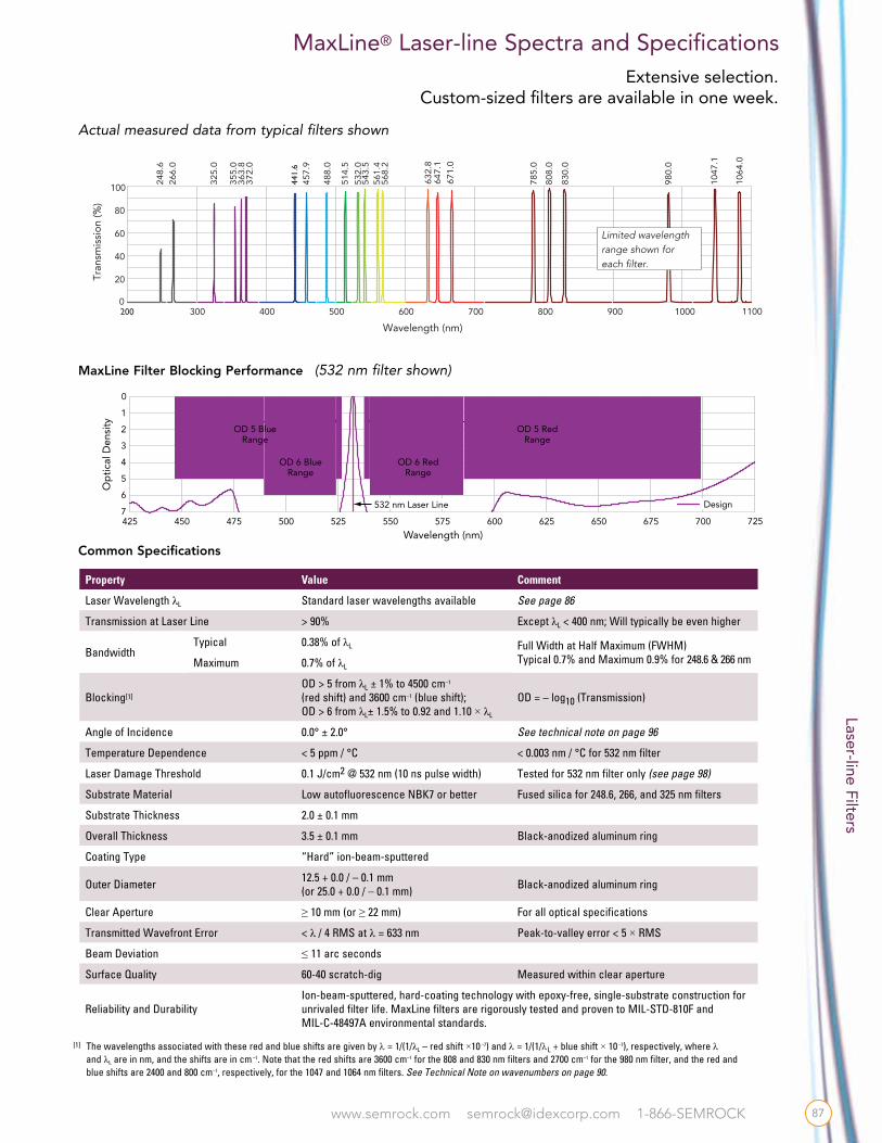
MaxLine® Laser-line Spectra and Specifications
[1] The wavelengths associated with these red and blue shifts are given by l = 1/(1/λL – red shift ×10 –7) and l = 1/(1/lL + blue shift × 10 –7), respectively, where l and λL are in nm, and the shifts are in cm –1. Note that the red shifts are 3600 cm–1 for the 808 and 830 nm filters and 2700 cm–1 for the 980 nm filter, and the red and blue shifts are 2400 and 800 cm–1, respectively, for the 1047 and 1064 nm filters. See Technical Note on wavenumbers on page 90.
Actual measured data from typical filters shown
MaxLine Filter Blocking Performance (532 nm filter shown)
475425 525 575 625 675500450 550 600 650 700
6
7
5
4
3
2
1
0
Op
tica
l Den
sity
Wavelength (nm)
Design532 nm Laser Line
725
OD 5 RedRange
OD 5 BlueRange
OD 6 BlueRange
OD 6 RedRange
Limited wavelength range shown foreach filter.
Property Value Comment
Laser Wavelength λL Standard laser wavelengths available See page 86
Transmission at Laser Line > 90% Except λL < 400 nm; Will typically be even higher
BandwidthTypical 0.38% of λL Full Width at Half Maximum (FWHM)
Typical 0.7% and Maximum 0.9% for 248.6 & 266 nmMaximum 0.7% of λL
Blocking[1]
OD > 5 from λL ± 1% to 4500 cm–1
(red shift) and 3600 cm–1 (blue shift);OD > 6 from λL± 1.5% to 0.92 and 1.10 × λL
OD = – log10 (Transmission)
Angle of Incidence 0.0° ± 2.0° See technical note on page 96
Temperature Dependence < 5 ppm / °C < 0.003 nm / °C for 532 nm filter
Laser Damage Threshold 0.1 J/cm2 @ 532 nm (10 ns pulse width) Tested for 532 nm filter only (see page 98)
Substrate Material Low autofluorescence NBK7 or better Fused silica for 248.6, 266, and 325 nm filters
Substrate Thickness 2.0 ± 0.1 mm
Overall Thickness 3.5 ± 0.1 mm Black-anodized aluminum ring
Coating Type “Hard” ion-beam-sputtered
Outer Diameter 12.5 + 0.0 / – 0.1 mm (or 25.0 + 0.0 / – 0.1 mm) Black-anodized aluminum ring
Clear Aperture ≥ 10 mm (or ≥ 22 mm) For all optical specifications
Transmitted Wavefront Error < λ / 4 RMS at λ = 633 nm Peak-to-valley error < 5 × RMS
Beam Deviation ≤ 11 arc seconds
Surface Quality 60-40 scratch-dig Measured within clear aperture
Reliability and DurabilityIon-beam-sputtered, hard-coating technology with epoxy-free, single-substrate construction for unrivaled filter life. MaxLine filters are rigorously tested and proven to MIL-STD-810F and MIL-C-48497A environmental standards.
Common Specifications
87
www.semrock.com [email protected] 1-866-SEMROCK
Filter Types for Raman Spectroscopy Applications
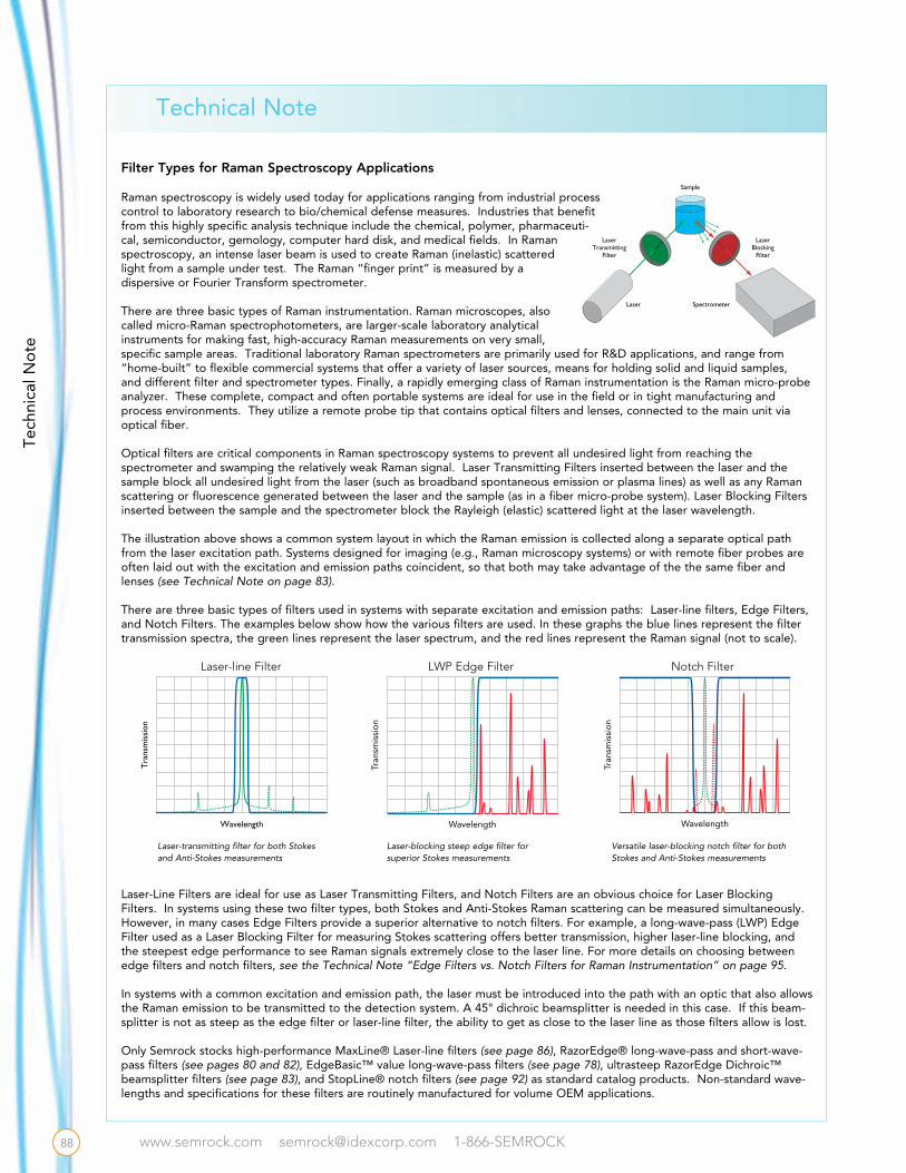
Raman spectroscopy is widely used today for applications ranging from industrial process control to laboratory research to bio/chemical defense measures. Industries that benefit from this highly specific analysis technique include the chemical, polymer, pharmaceuti-cal, semiconductor, gemology, computer hard disk, and medical fields. In Raman spectroscopy, an intense laser beam is used to create Raman (inelastic) scattered light from a sample under test. The Raman “finger print” is measured by a dispersive or Fourier Transform spectrometer.
There are three basic types of Raman instrumentation. Raman microscopes, also called micro-Raman spectrophotometers, are larger-scale laboratory analytical instruments for making fast, high-accuracy Raman measurements on very small, specific sample areas. Traditional laboratory Raman spectrometers are primarily used for R&D applications, and range from “home-built” to flexible commercial systems that offer a variety of laser sources, means for holding solid and liquid samples, and different filter and spectrometer types. Finally, a rapidly emerging class of Raman instrumentation is the Raman micro-probe analyzer. These complete, compact and often portable systems are ideal for use in the field or in tight manufacturing and process environments. They utilize a remote probe tip that contains optical filters and lenses, connected to the main unit via optical fiber.
Optical filters are critical components in Raman spectroscopy systems to prevent all undesired light from reaching the spectrometer and swamping the relatively weak Raman signal. Laser Transmitting Filters inserted between the laser and the sample block all undesired light from the laser (such as broadband spontaneous emission or plasma lines) as well as any Raman scattering or fluorescence generated between the laser and the sample (as in a fiber micro-probe system). Laser Blocking Filters inserted between the sample and the spectrometer block the Rayleigh (elastic) scattered light at the laser wavelength.
The illustration above shows a common system layout in which the Raman emission is collected along a separate optical path from the laser excitation path. Systems designed for imaging (e.g., Raman microscopy systems) or with remote fiber probes are often laid out with the excitation and emission paths coincident, so that both may take advantage of the the same fiber and lenses (see Technical Note on page 83).
There are three basic types of filters used in systems with separate excitation and emission paths: Laser-line filters, Edge Filters, and Notch Filters. The examples below show how the various filters are used. In these graphs the blue lines represent the filter transmission spectra, the green lines represent the laser spectrum, and the red lines represent the Raman signal (not to scale).
Laser-Line Filters are ideal for use as Laser Transmitting Filters, and Notch Filters are an obvious choice for Laser Blocking Filters. In systems using these two filter types, both Stokes and Anti-Stokes Raman scattering can be measured simultaneously. However, in many cases Edge Filters provide a superior alternative to notch filters. For example, a long-wave-pass (LWP) Edge Filter used as a Laser Blocking Filter for measuring Stokes scattering offers better transmission, higher laser-line blocking, and the steepest edge performance to see Raman signals extremely close to the laser line. For more details on choosing between edge filters and notch filters, see the Technical Note “Edge Filters vs. Notch Filters for Raman Instrumentation” on page 95.
In systems with a common excitation and emission path, the laser must be introduced into the path with an optic that also allows the Raman emission to be transmitted to the detection system. A 45° dichroic beamsplitter is needed in this case. If this beam-splitter is not as steep as the edge filter or laser-line filter, the ability to get as close to the laser line as those filters allow is lost.
Only Semrock stocks high-performance MaxLine® Laser-line filters (see page 86), RazorEdge® long-wave-pass and short-wave-pass filters (see pages 80 and 82), EdgeBasic™ value long-wave-pass filters (see page 78), ultrasteep RazorEdge Dichroic™ beamsplitter filters (see page 83), and StopLine® notch filters (see page 92) as standard catalog products. Non-standard wave-lengths and specifications for these filters are routinely manufactured for volume OEM applications.
Tra
nsm
issi
on
Wavelength
Laser-line Filter
Tran
smis
sio
n
Wavelength
LWP Edge Filter
Laser-transmitting filter for both Stokes and Anti-Stokes measurements
Laser-blocking steep edge filter for superior Stokes measurements
Tran
smis
sio
n
Wavelength
Notch Filter
Versatile laser-blocking notch filter for both Stokes and Anti-Stokes measurements
Sample
SpectrometerLaser
LaserBlocking
Filter
LaserTransmitting
Filter
Technical Note
88
Tech
nica
l No
te
88
www.semrock.com [email protected] 1-866-SEMROCK
Actual measured data shown
500 700600400
405 439 473 640
0
20
40
60
80
100
Tran
smis
sio
n (%
)
Wavelength (nm)350 450 550 650
375
750 800
785
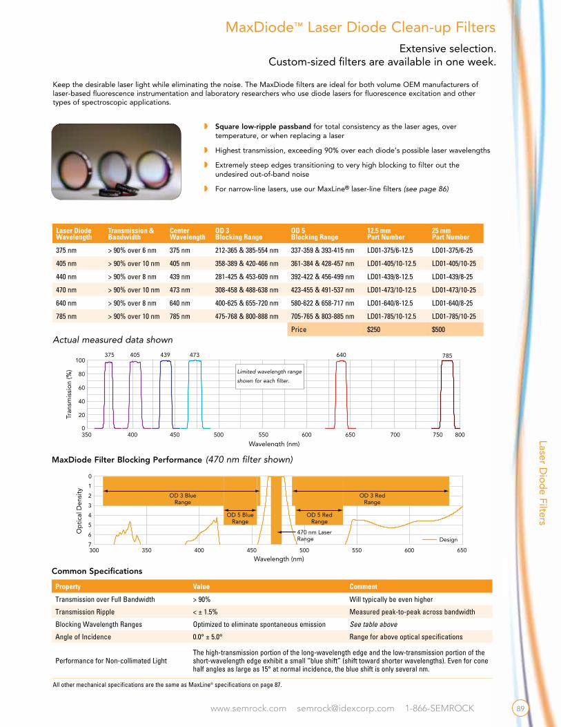
w Square low-ripple passband for total consistency as the laser ages, over temperature, or when replacing a laser
w Highest transmission, exceeding 90% over each diode’s possible laser wavelengths
w Extremely steep edges transitioning to very high blocking to filter out the undesired out-of-band noise
w For narrow-line lasers, use our MaxLine® laser-line filters (see page 86)
Keep the desirable laser light while eliminating the noise. The MaxDiode filters are ideal for both volume OEM manufacturers of laser-based fluorescence instrumentation and laboratory researchers who use diode lasers for fluorescence excitation and other types of spectroscopic applications.
MaxDiode™ Laser Diode Clean-up Filters
Common Specifications
600
Wavelength (nm)
470 nm LaserRange
OD 3 RedRange
OD 3 BlueRange
OD 5 BlueRange
OD 5 RedRange
Design
400300 500 600450350 550 650
6
7
5
4
3
2
1
0
Op
tica
l Den
sity
MaxDiode Filter Blocking Performance (470 nm filter shown)
All other mechanical specifications are the same as MaxLine® specifications on page 87.
Limited wavelength range
shown for each filter.
Laser Diode Wavelength
Transmission & Bandwidth
Center Wavelength
OD 3Blocking Range
OD 5Blocking Range
12.5 mm Part Number
25 mm Part Number
375 nm > 90% over 6 nm 375 nm 212-365 & 385-554 nm 337-359 & 393-415 nm LD01-375/6-12.5 LD01-375/6-25
405 nm > 90% over 10 nm 405 nm 358-389 & 420-466 nm 361-384 & 428-457 nm LD01-405/10-12.5 LD01-405/10-25
440 nm > 90% over 8 nm 439 nm 281-425 & 453-609 nm 392-422 & 456-499 nm LD01-439/8-12.5 LD01-439/8-25
470 nm > 90% over 10 nm 473 nm 308-458 & 488-638 nm 423-455 & 491-537 nm LD01-473/10-12.5 LD01-473/10-25
640 nm > 90% over 8 nm 640 nm 400-625 & 655-720 nm 580-622 & 658-717 nm LD01-640/8-12.5 LD01-640/8-25
785 nm > 90% over 10 nm 785 nm 475-768 & 800-888 nm 705-765 & 803-885 nm LD01-785/10-12.5 LD01-785/10-25
Price $250 $500
Property Value Comment
Transmission over Full Bandwidth > 90% Will typically be even higher
Transmission Ripple < ± 1.5% Measured peak-to-peak across bandwidth
Blocking Wavelength Ranges Optimized to eliminate spontaneous emission See table above
Angle of Incidence 0.0° ± 5.0° Range for above optical specifications
Performance for Non-collimated LightThe high-transmission portion of the long-wavelength edge and the low-transmission portion of the short-wavelength edge exhibit a small “blue shift” (shift toward shorter wavelengths). Even for cone half angles as large as 15° at normal incidence, the blue shift is only several nm.
Laser Dio
de Filters
89
Extensive selection. Custom-sized filters are available in one week.

www.semrock.com [email protected] 1-866-SEMROCK
Every Semrock filter is hard-coated for durable performance.Five-year warranty.
Near Infrared Bandpass Filters
When speaking of a “shift” from a first known wavelength λ1 to a second known wavelength λ2, the resulting wave-length shift ∆λ is given by
whereas the resulting wavenumber shift ∆w is given by
When speaking of a known wavenumber shift ∆w from a first known wavelength λ1, the resulting second wavelength λ2 is given by
Note that when the final wavelength λ2 is longer than the initial wavelength λ1, which corresponds to a “red shift,” in the above equations ∆w < 0, consistent with a shift toward smaller values of w. However, when the final wavelength λ2 is shorter than the initial wavelength λ1, which corresponds to a “blue shift,” ∆w > 0, consistent with a shift toward larger values of w.
The “color” of light is generally identified by the distribution of power or intensity as a function of wavelength λ. For example, visible light has a wavelength that ranges from about 400 nm to just over 700 nm. However, sometimes it is convenient to describe light in terms of units called “wavenumbers,” where the wavenumber w is typically measured in units of cm-1 (“inverse centimeters”) and is simply equal to the inverse of the wavelength:
In applications like Raman spectroscopy, often both wave-length and wavenumber units are used together, leading to potential confusion. For example, laser lines are generally identified by wavelength, but the separation of a particular Raman line from the laser line is generally given by a “wavenumber shift” ∆w, since this quantity is fixed by the molecular properties of the material and independent of which laser wavelength is used to excite the line.
Measuring Light with Wavelengths and Wavenumbers
300200 500400 600
Wavelength (nm)
Wavenumbers (cm-1)
700
VisibleUV Near-UV
800 1000900 1100 1200
33,33350,000 20,00025,000 16,667 14,286 12,500 10,00011,111 9,091 8,333
Near-IR
For graphs, ASCII data and blocking information, go to www.semrock.com
Center Wavelength
Transmission & Bandwidth
NominalFull-width,Half-Maximum
OD 5Blocking Range
OD 6Blocking Range Part Number Price
1535 nm > 90% over 3 nm 6.8 nm 850 – 1519 nm1550 – 1750 nm
1412 – 1512 nm1558 – 1688 nm NIR01-1535/3-25 $395
1550 nm > 90% over 3 nm 8.8 nm 850 – 1534 nm1565 – 1750 nm
1426 – 1526 nm1573 – 1705 nm NIR01-1550/3-25 $395
1570 nm > 90% over 3 nm 8.9 nm 850 – 1554 nm1585 – 1750 nm
1444 – 1546 nm1593 – 1727 nm NIR01-1570/3-25 $395
LDT specification = 1J/cm2 @1570 nm (10ns pulse width)
Semrock’s industry-leading ion-beam-sputtering manufacturing is now available for making optical filters with precise spectral features (sharp edges, passbands, etc.) at near-IR wavelengths, with features out to ~ 1700 nm, and high transmission to wave-lengths > 2000 nm. The bandpass filters on this page are ideal as laser source clean-up filters and as detection filters which pass particular laser wavelengths and virtually eliminate background over the full InGaAs detector range (850 – 1750 nm). They are optimized for the most popular “retina-safe” lasers in the 1.5 μm wavelength range, where maximum permissible eye exposures are much higher than in the visible or at the 1.06 μm neodymium line. Applications include laser radar, remote sensing, range-finding, and laser-induced breakdown spectroscopy (LIBS).
Except for the transmission, bandwidth, and blocking specifications listed above, all other specifications are identical to MaxLine® specifications on page 87.
15101500 1520 1540 1560 15801530 1550 1570 15900
10
20
30
40
50
60
70
80
90
100
Tran
smis
sion
(%)
Wavelength (nm)1600
1535 1550 1570
DesignSpectra
Near-IR bandpass filters are a good match for Er-doped fiber and Er-doped glass lasers at 1535 nm, r-doped fiber and InGaAsP semiconductor lasers at 1550 nm, and Nd:YAG-pumped optical parametric oscillators (OPO’s) at 1570 nm.
Technical Note
90
NIR
Ban
dp
ass
Filt
ers
www.semrock.com [email protected] 1-866-SEMROCK
MaxLamp™ Mercury Line Filters
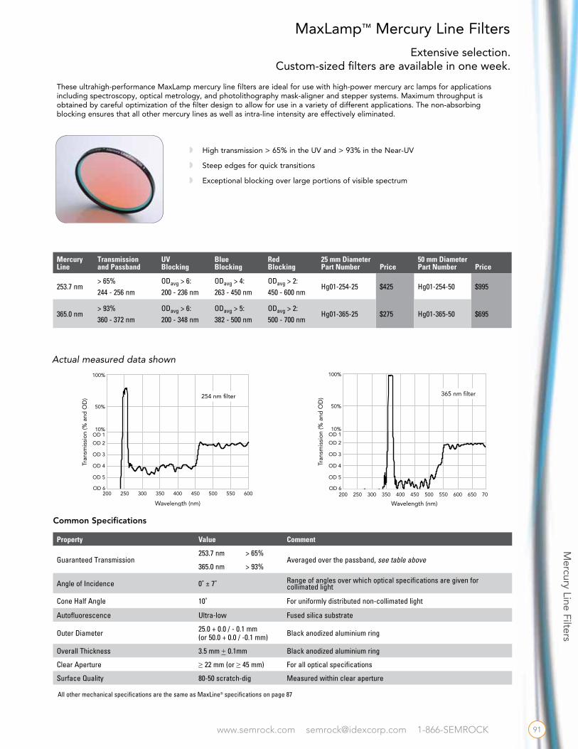
These ultrahigh-performance MaxLamp mercury line filters are ideal for use with high-power mercury arc lamps for applications including spectroscopy, optical metrology, and photolithography mask-aligner and stepper systems. Maximum throughput is obtained by careful optimization of the filter design to allow for use in a variety of different applications. The non-absorbing blocking ensures that all other mercury lines as well as intra-line intensity are effectively eliminated.
w High transmission > 65% in the UV and > 93% in the Near-UV
w Steep edges for quick transitions
w Exceptional blocking over large portions of visible spectrum
Common Specifications
Property Value Comment
Guaranteed Transmission253.7 nm > 65%
Averaged over the passband, see table above365.0 nm > 93%
Angle of Incidence 0˚ ± 7˚ Range of angles over which optical specifications are given for collimated light
Cone Half Angle 10˚ For uniformly distributed non-collimated light
Autofluorescence Ultra-low Fused silica substrate
Outer Diameter 25.0 + 0.0 / - 0.1 mm (or 50.0 + 0.0 / -0.1 mm) Black anodized aluminium ring
Overall Thickness 3.5 mm + 0.1mm Black anodized aluminium ring
Clear Aperture ≥ 22 mm (or ≥ 45 mm) For all optical specifications
Surface Quality 80-50 scratch-dig Measured within clear aperture
Mercury Line
Transmission and Passband
UVBlocking
Blue Blocking
Red Blocking
25 mm Diameter Part Number Price
50 mm Diameter Part Number Price
253.7 nm> 65% 244 - 256 nm
ODavg > 6: 200 - 236 nm
ODavg > 4: 263 - 450 nm
ODavg > 2: 450 - 600 nm
Hg01-254-25 $425 Hg01-254-50 $995
365.0 nm> 93% 360 - 372 nm
ODavg > 6: 200 - 348 nm
ODavg > 5: 382 - 500 nm
ODavg > 2: 500 - 700 nm
Hg01-365-25 $275 Hg01-365-50 $695
Actual measured data shown
200 300250 400350 450 600OD 6
OD 5
OD 4
OD 3
OD 2
OD 110%
50%
100%
Tran
smis
sio
n (%
and
OD
)
Wavelength (nm)
500 550
254 nm filter
600OD 6
OD 5
OD 4
OD 3
OD 2
OD 110%
50%
100%
Tran
smis
sio
n (%
and
OD
)
550200 300250 400350 450
Wavelength (nm)
650 700500
365 nm filter
All other mechanical specifications are the same as MaxLine® specifications on page 87
Mercury Line Filters
91
Extensive selection. Custom-sized filters are available in one week.

www.semrock.com [email protected] 1-866-SEMROCK
No
tch
Filt
ers
Every Semrock filter is hard-coated for durable performance.Five-year warranty.
StopLine deep notch filters rival the performance of holographic notch filters but in a less expensive, more convenient, and more reliable thin-film filter format (U.S. Patents No. 7,123,416 and pending). These filters are ideal for applications including Raman spectroscopy, laser-based fluorescence instruments, and biomedical laser systems.
w The stunning StopLine E-grade notch filters offer high transmission over ultra-wide passbands (UV to 1600 nm)w Deep laser-line blocking for maximum laser rejection (OD > 6)w High laser damage threshold and proven reliabilityw Rejected light is reflected, for convenient alignment and best stray-light controlw Multi-notch filters are available for blocking multiple laser lines (see page 94)
Semrock introduced a breakthrough invention in thin-film optical filters: our StopLine “E-grade” thin-film notch filters have ultrawide passbands with deep and narrow laser-line blocking. Unheard of previously in a thin-film notch filter made with multiple, discrete layers, these new patent-pending notch filters attenuate the laser wavelength with OD > 6 while passing light from the UV well into the near-infrared (1600 nm). They are especially suited for optical systems addressing multiple regions of the optical spectrum (e.g., UV, Visible, and Near-IR), and for systems based on multiple detection modes (e.g., fluorescence, Raman spectroscopy, laser-induced breakdown spectroscopy, etc.).
StopLine® Single-notch Filters
Wavelength Passband RangeTypical 50% Notch Bandwidth Laser-line Blocking Part Number Price
405.0 nm 330.0 – 1600.0 nm 9 nm OD > 6 NF03-405E-25 $795
488.0 nm 350.0 – 1600.0 nm 14 nm OD > 6 NF03-488E-25 $795
514.5 nm 350.0 – 1600.0 nm 16 nm OD > 6 NF03-514E-25 $795
532.0 nm 350.0 – 1600.0 nm 399.0 – 709.3 nm
17 nm17 nm
OD > 6 OD > 6
NF03-532E-25NF01-532U-25
$795$625
561.4 nm 350.0 – 1600.0 nm 19 nm OD > 6 NF03-561E-25 $795
594.1 nm 350.0 – 1600.0 nm 22 nm OD > 6 NF03-594E-25 $795
632.8 nm 350.0 – 1600.0 nm 25 nm OD > 6 NF03-633E-25 $795
658.0 nm 350.0 – 1600.0 nm 27 nm OD > 6 NF03-658E-25 $795
785.0 nm 350.0 – 1600.0 nm 39 nm OD > 6 NF03-785E-25 $795
808.0 nm 350.0 – 1600.0 nm 41 nm OD > 6 NF03-808E-25 $795
New!
550350 750 1150950 1350 16007
6
5
4
3
2
1
0
Op
tica
l Den
sity
Wavelength (nm)
500490 510 530520 540 550 560 570 5807
6
5
4
3
2
1
0
Op
tica
l Den
sity
Wavelength (nm)
550350 750 1150950 1350 16007
6
5
4
3
2
1
0
Op
tica
l Den
sity
Wavelength (nm)
500490 510 530520 540 550 560 570 5807
6
5
4
3
2
1
0
Op
tica
l Den
sity
Wavelength (nm)
Looking for a 1064 nm notch filter? Try the NF03-532/1064E on page 94.
NF03-532ETypical Measured Data
NF03-561ETypical Measured Data
92
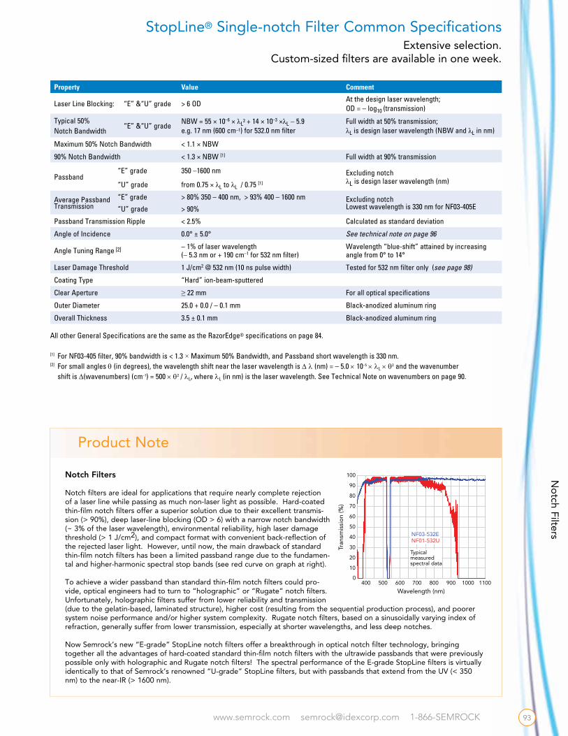
www.semrock.com [email protected] 1-866-SEMROCK
Notch Filters
Notch filters are ideal for applications that require nearly complete rejection of a laser line while passing as much non-laser light as possible. Hard-coated thin-film notch filters offer a superior solution due to their excellent transmis-sion (> 90%), deep laser-line blocking (OD > 6) with a narrow notch bandwidth (~ 3% of the laser wavelength), environmental reliability, high laser damage threshold (> 1 J/cm2), and compact format with convenient back-reflection of the rejected laser light. However, until now, the main drawback of standard thin-film notch filters has been a limited passband range due to the fundamen-tal and higher-harmonic spectral stop bands (see red curve on graph at right).
To achieve a wider passband than standard thin-film notch filters could pro-vide, optical engineers had to turn to “holographic” or “Rugate” notch filters. Unfortunately, holographic filters suffer from lower reliability and transmission (due to the gelatin-based, laminated structure), higher cost (resulting from the sequential production process), and poorer system noise performance and/or higher system complexity. Rugate notch filters, based on a sinusoidally varying index of refraction, generally suffer from lower transmission, especially at shorter wavelengths, and less deep notches.
Now Semrock’s new “E-grade” StopLine notch filters offer a breakthrough in optical notch filter technology, bringing together all the advantages of hard-coated standard thin-film notch filters with the ultrawide passbands that were previously possible only with holographic and Rugate notch filters! The spectral performance of the E-grade StopLine filters is virtually identically to that of Semrock’s renowned “U-grade” StopLine filters, but with passbands that extend from the UV (< 350 nm) to the near-IR (> 1600 nm).
StopLine® Single-notch Filter Common Specifications
All other General Specifications are the same as the RazorEdge® specifications on page 84.
[1] For NF03-405 filter, 90% bandwidth is < 1.3 × Maximum 50% Bandwidth, and Passband short wavelength is 330 nm. [2] For small angles q (in degrees), the wavelength shift near the laser wavelength is D l (nm) = – 5.0 × 10⁻⁵ × lL × q2 and the wavenumber shift is D(wavenumbers) (cm–1) = 500 × q2 / lL, where lL (in nm) is the laser wavelength. See Technical Note on wavenumbers on page 90.
Property Value Comment
Laser Line Blocking: “E” &“U” grade > 6 ODAt the design laser wavelength; OD = – log10 (transmission)
Typical 50% Notch Bandwidth
“E” &“U” gradeNBW = 55 × 10–6 × λL2 + 14 × 10–3 ×λL – 5.9e.g. 17 nm (600 cm–1) for 532.0 nm filter
Full width at 50% transmission; λL is design laser wavelength (NBW and λL in nm)
Maximum 50% Notch Bandwidth < 1.1 × NBW
90% Notch Bandwidth < 1.3 × NBW [1] Full width at 90% transmission
Passband“E” grade 350 –1600 nm Excluding notch
λL is design laser wavelength (nm)“U” grade from 0.75 × λL to λL / 0.75 [1]
Average Passband Transmission
“E” grade > 80% 350 – 400 nm, > 93% 400 – 1600 nm Excluding notch Lowest wavelength is 330 nm for NF03-405E“U” grade > 90%
Passband Transmission Ripple < 2.5% Calculated as standard deviation
Angle of Incidence 0.0° ± 5.0° See technical note on page 96
Angle Tuning Range [2] – 1% of laser wavelength (– 5.3 nm or + 190 cm–1 for 532 nm filter)
Wavelength “blue-shift” attained by increasing angle from 0° to 14°
Laser Damage Threshold 1 J/cm2 @ 532 nm (10 ns pulse width) Tested for 532 nm filter only (see page 98)
Coating Type “Hard” ion-beam-sputtered
Clear Aperture ≥ 22 mm For all optical specifications
Outer Diameter 25.0 + 0.0 / – 0.1 mm Black-anodized aluminum ring
Overall Thickness 3.5 ± 0.1 mm Black-anodized aluminum ring
500 600400 700 900800 1000 11000
10
20
30
40
50
60
70
80
90
100
Tran
smis
sio
n (%
)
Wavelength (nm)
NF01-532UNF03-532E
Typicalmeasuredspectral data
500490 510 530520 540 550 560 570 5807
6
5
4
3
2
1
0
Op
tica
l Den
sity
Wavelength (nm)
NF03-532E
Typicalmeasuredspectral data
Product Note
Extensive selection. Custom-sized filters are available in one week.
No
tch Filters
93
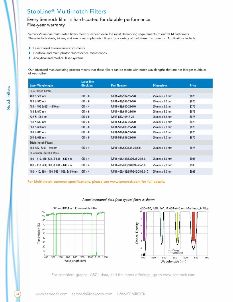
www.semrock.com [email protected] 1-866-SEMROCK
Laser WavelengthsLaser-line Blocking Part Number Dimensions Price
Dual-notch Filters
488 & 532 nm OD > 6 NF01-488/532-25x5.0 25 mm x 5.0 mm $875
488 & 543 nm OD > 6 NF01-488/543-25x5.0 25 mm x 5.0 mm $875
486 − 490 & 631 − 640 nm OD > 4 NF01-488/635-25x5.0 25 mm x 5.0 mm $775
488 & 647 nm OD > 6 NF01-488/647-25x5.0 25 mm x 5.0 mm $875
532 & 1064 nm OD > 6 NF03-532/1064E-25 25 mm x 3.5 mm $875
543 & 647 nm OD > 6 NF01-543/647-25x5.0 25 mm x 5.0 mm $875
568 & 638 nm OD > 6 NF01-568/638-25x5.0 25 mm x 5.0 mm $875
568 & 647 nm OD > 6 NF01-568/647-25x5.0 25 mm x 5.0 mm $875
594 & 638 nm OD > 6 NF01-594/638-25x5.0 25 mm x 5.0 mm $875
Triple-notch Filters
488, 532, & 631-640 nm OD > 4 NF01-488/532/635-25x5.0 25 mm x 5.0 mm $875
Quadruple-notch Filters
400 − 410, 488, 532, & 631 − 640 nm OD > 4 NF01-405/488/532/635-25x5.0 25 mm x 5.0 mm $995
400 − 410, 488, 561, & 631 − 640 nm OD > 4 NF01-405/488/561/635-25x5.0 25 mm x 5.0 mm $995
400− 410, 488 − 490, 555 − 559, & 640 nm OD > 4 NF01-405/488/557/640-25x5.0-D 25 mm x 5.0 mm $995
w Laser-based fluorescence instrumentsw Confocal and multi-photon fluorescence microscopes
w Analytical and medical laser systems
Semrock’s unique multi-notch filters meet or exceed even the most demanding requirements of our OEM customers. These include dual-, triple-, and even quadruple-notch filters for a variety of multi-laser instruments. Applications include:
Actual measured data from typical filters is shown
DesignMeasured
Opt
ical
Den
sity
Wavelength (nm)400 450 500 550 600 7006
5
4
3
2
1
0
650
400-410, 488, 561, & 631-640 nm Multi-notch Filter
For complete graphs, ASCII data, and the latest offerings, go to www.semrock.com.
StopLine® Multi-notch Filters
Our advanced manufacturing process means that these filters can be made with notch wavelengths that are not integer multiples of each other!
For Multi-notch common specifications, please see www.semrock.com for full details.
500400 600 700 800 10000
10
20
30
40
50
60
70
80
90
100
900 1100
Tran
smis
sio
n (%
)
Wavelength (nm)1200
532 and1064 nm Dual-notch Filter
94
No
tch
Filt
ers
Every Semrock filter is hard-coated for durable performance.Five-year warranty.
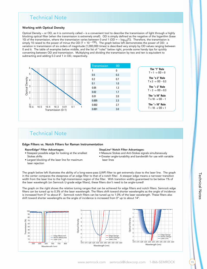
www.semrock.com [email protected] 1-866-SEMROCK
Technical Note
Technical Note
Working with Optical Density
Optical Density – or OD, as it is commonly called – is a convenient tool to describe the transmission of light through a highly blocking optical filter (when the transmission is extremely small). OD is simply defined as the negative of the logarithm (base 10) of the transmission, where the transmission varies between 0 and 1 (OD = – log10(T)). Therefore, the transmission is simply 10 raised to the power of minus the OD (T = 10 – OD). The graph below left demonstrates the power of OD: a variation in transmission of six orders of magnitude (1,000,000 times) is described very simply by OD values ranging between 0 and 6. The table of examples below middle, and the list of “rules” below right, provide some handy tips for quickly converting between OD and transmission. Multiplying and dividing the transmission by two and ten is equivalent to subtracting and adding 0.3 and 1 in OD, respectively.
The “1” RuleT = 1 → OD = 0
The “x 2” RuleT x 2 → OD – 0.3
The “÷ 2” RuleT ÷ 2 → OD + 0.3
The “x 10” RuleT x 10 → OD – 1
The “÷ 10” RuleT ÷ 10 → OD + 1
Op
tica
l Den
sity
Transmission (0-1) 1E-6 1E-5 1E-4 1E-3 10
1
2
3
4
5
6
0.10.01
610 615 620 625 630 635 640 645 650 655 6608
7
6
5
4
3
2
1
0
Op
tica
l Den
sity
Wavelength (nm)
Edge DesignNotch DesignLaser Line
610 615 620 625 630 635 640 645 650 655 6608
7
6
5
4
3
2
1
0
Op
tica
l Den
sity
Wavelength (nm)
Edge DesignNotch DesignLaser Line
550 600 650 700 750 8000
10
20
30
40
50
60
70
80
90
100
Tran
smis
sio
n (%
)
Wavelength (nm)
Edge MeasuredNotch MeasuredLaser Line
610 615 620 625 630 635 640 645 650 655 6608
7
6
5
4
3
2
1
0
Op
tica
l Den
sity
Wavelength (nm)
Edge DesignNotch DesignLaser Line
610 615 620 625 630 635 640 645 650 655 6608
7
6
5
4
3
2
1
0
Op
tica
l Den
sity
Wavelength (nm)
Edge DesignNotch DesignLaser Line
550 600 650 700 750 8000
10
20
30
40
50
60
70
80
90
100
Tran
smis
sio
n (%
)
Wavelength (nm)
Edge MeasuredNotch MeasuredLaser Line 610 615 620 625 630 635 640 645 650 655 660
8
7
6
5
4
3
2
1
0
Op
tica
l Den
sity
Wavelength (nm)
Edge DesignNotch DesignLaser Line
610 615 620 625 630 635 640 645 650 655 6608
7
6
5
4
3
2
1
0
Op
tica
l Den
sity
Wavelength (nm)
Edge DesignNotch DesignLaser Line
550 600 650 700 750 8000
10
20
30
40
50
60
70
80
90
100
Tran
smis
sio
n (%
)
Wavelength (nm)
Edge MeasuredNotch MeasuredLaser Line
Edge Filters vs. Notch Filters for Raman Instrumentation
RazorEdge® Filter Advantages:• Steepest possible edge for looking at the smallest Stokes shifts • Largest blocking of the laser line for maximum laser rejection
StopLine® Notch Filter Advantages:• Measure Stokes and Anti-Stokes signals simultaneously • Greater angle-tunability and bandwidth for use with variable
laser lines
The graph below left illustrates the ability of a long-wave-pass (LWP) filter to get extremely close to the laser line. The graph in the center compares the steepness of an edge filter to that of a notch filter. A steeper edge means a narrower transition width from the laser line to the high-transmission region of the filter. With transition widths guaranteed to be below 1% of the laser wavelength (on Semrock U-grade edge filters), these filters don’t need to be angle-tuned!
The graph on the right shows the relative tuning ranges that can be achieved for edge filters and notch filters. Semrock edge filters can be tuned up to 0.3% of the laser wavelength. The filters shift toward shorter wavelengths as the angle of incidence is increased from 0° to about 8°. Semrock notch filters can be tuned up to 1.0% of the laser wavelength. These filters also shift toward shorter wavelengths as the angle of incidence is increased from 0° up to about 14°.
Technical No
tes
Transmission OD1 0
0.5 0.3
0.2 0.7
0.1 1.0
0.05 1.3
0.02 1.7
0.01 2.0
0.005 2.3
0.002 2.7
0.001 3.0
95

www.semrock.com [email protected] 1-866-SEMROCK
Technical Note
Filter Spectra at Non-normal Angles of Incidence
Many of the filters in this catalog (with the exception of dichroic beamsplitters, polarization, and the MaxMirror®) are optimized for use with light at or near normal incidence. However, for some applications it is desirable to understand how the spectral properties change for a non-zero angle of incidence (AOI).
There are two main effects exhibited by the filter spectrum as the angle is increased from normal:1. the features of the spectrum shift to shorter wavelengths;2. two distinct spectra emerge – one for s-polarized light and one for p-polarized light.
As an example, the graph at the right shows a series of spectra derived from a typical RazorEdge long-wave-pass (LWP) filter design. Because the designs are so similar for all of the RazorEdge filters designed for normal incidence (see page 65), the set of curves in the graph can be applied approximately to any of the filters. Here the wavelength λ is compared to the wavelength λ0 of a particular spectral feature (in this case the edge location) at normal incidence. As can be seen from the spec-tral curves, as the angle is increased from normal incidence the filter edge shifts toward shorter wavelengths and the edges associated with s- and p-polarized light shift by different amounts. For LWP filters, the edge associated with p-polarized light shifts more than the edge associated with s-polarized light, whereas for short-wave-pass (SWP) filters the opposite is true. Because of this polarization splitting, the spectrum for unpolarized light demonstrates a “shelf” near the 50% transmission point when the splitting significantly exceeds the edge steepness. However, the edge steepness for polarized light remains very high.
The shift of almost any spectral feature can be approximately quantified by a simple model of the wavelength λ of the feature vs. angle of incidence θ, given by the equation:
where neff is called the effective index of refraction, and λ0 is the wave-length of the spectral feature of interest at normal incidence. Different shifts that occur for different spectral features and different filters are described by a different effective index. For the RazorEdge example above, the shift of the 90% transmission point on the edge is described by this equation with neff = 2.08 and 1.62 for s- and p-polarized light, respectively.
Other types of filters don’t necessarily exhibit such a marked difference in the shift of features for s- and p-polarized light. For example, the middle graph shows a series of spectra derived from a typical MaxLine laser-line filter design curve (see page 72). As the angle is increased from normal incidence, the center wavelength shifts toward shorter wavelengths and the bandwidth broadens slightly for p-polarized light while narrowing for s-polarized light. The center wavelength shifts are described by the above equation with neff = 2.19 and 2.13 for s- and p-polarized light, respectively. The most striking feature is the decrease in transmission for s-polarized light, whereas the transmission remains quite high for p-polarized light. As another example, the graph at the right shows a series of spectra derived from a typical E-grade StopLine notch filter design curve (see page 77). As the angle is increased from normal incidence, the notch center wavelength shifts to shorter wavelengths; however, the shift is greater for p-polarized light than it is for s-polarized light. The shift is described by the above equation with neff = 1.71 and 1.86 for p- and s-polarized light, respectively. Further, whereas the notch depth and bandwidth both decrease as the angle of incidence is increased for p-polarized light, in contrast the notch depth and bandwidth increase for s-polarized light. Note that it is possible to optimize the design of a notch filter to have a very deep notch even at a 45° angle of incidence.
0.88 0.90 0.92 0.94 0.96 0.98 1.00 1.02 1.04 1.06 1.080
10
20
30
40
50
60
70
80
90
100
Tran
smis
sio
n (%
)Relative Wavelength (λ/λ0)
0°
10° s
10° avg
10° p
30° s
30° avg
30° p
45° s
45° avg
45° p
RazorEdge™ Design Spectra vs. AOI
Op
tica
l Den
sity
Relative Wavelength (λ/λ0)
0.88 0.90 0.92 0.94 0.96 0.98 1.00 1.02 1.04 1.06 1.087
6
5
4
3
2
1
0
0°
10° s
10° avg
10° p
30° s
30° avg
30° p
45° s
45° avg
45° p
RazorEdge® Design Spectra vs. AOI
0.88 0.90 0.92 0.94 0.96 0.98 1.00 1.02 1.04 1.06 1.08
Op
tical
Den
sity
Relative Wavelength (λ/λ0)
0°
10° s
10° avg
10° p
30° s
30° avg
30° p
45° s
45° avg
45° p
StopLine® E-grade Design Spectra vs. AOI
8
6
7
5
4
3
2
1
0
StopLine® E Grade Design Spectra vs. AOI
= l(q) 0l 1–(sinq/neff)2
0.88 0.90 0.92 0.94 0.96 0.98 1.00 1.02 1.04 1.06 1.080
10
20
30
40
50
60
70
80
90
100
Tran
smis
sio
n (%
)
Relative Wavelength (λ/λ0)
0°
10° s
10° avg
10° p
30° s
30° avg
30° p
45° s
45° avg
45° p
MaxLine® Design Spectra vs. AOI
96
Tech
nica
l No
te
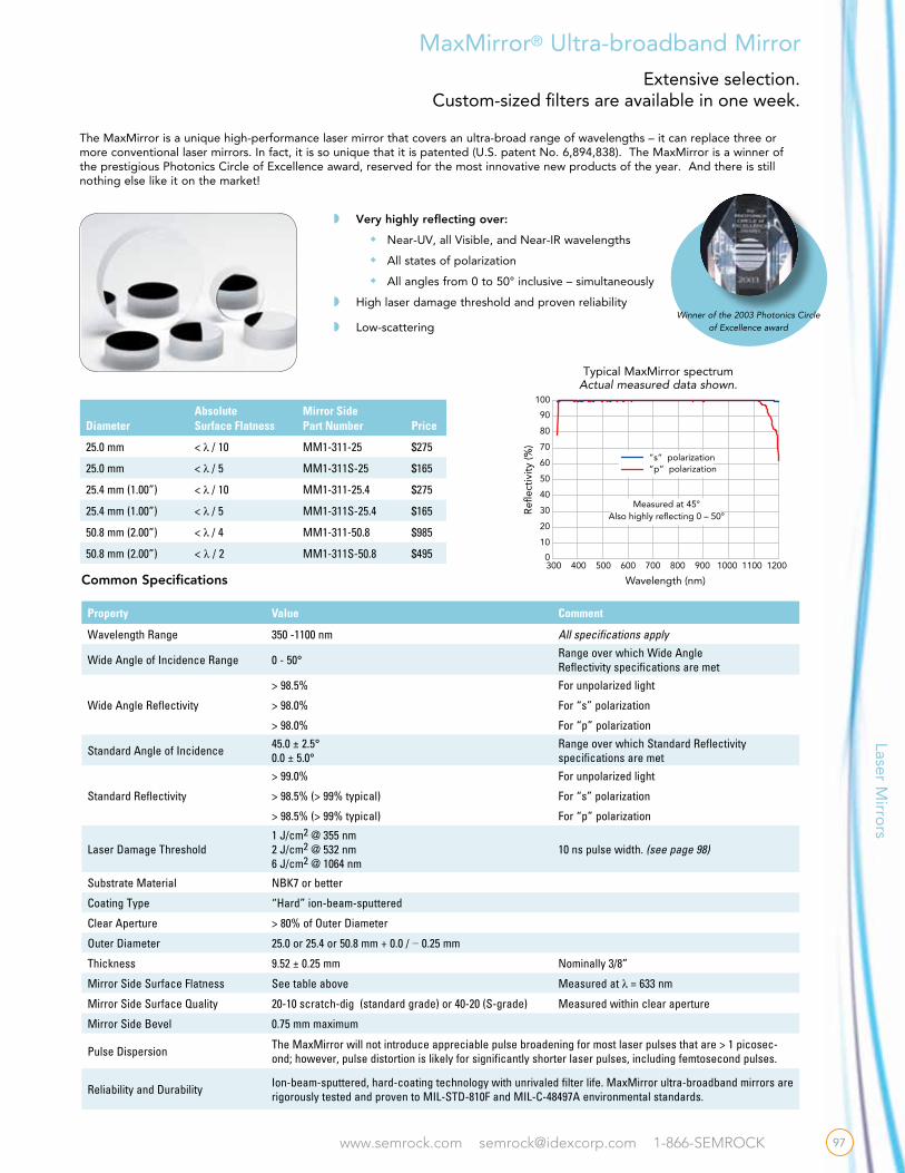
www.semrock.com [email protected] 1-866-SEMROCK
w Very highly reflecting over:
w Near-UV, all Visible, and Near-IR wavelengths
w All states of polarization
w All angles from 0 to 50° inclusive – simultaneously
w High laser damage threshold and proven reliability
w Low-scattering
0
10
20
30
40
50
60
70
80
90
100
Refl
ecti
vity
(%)
Wavelength (nm)
300 400 500 600 700 800 900 1000 1100 1200
“s” polarization“p” polarization
Measured at 45°Also highly reflecting 0 – 50°
Typical MaxMirror spectrumActual measured data shown.
The MaxMirror is a unique high-performance laser mirror that covers an ultra-broad range of wavelengths – it can replace three or more conventional laser mirrors. In fact, it is so unique that it is patented (U.S. patent No. 6,894,838). The MaxMirror is a winner of the prestigious Photonics Circle of Excellence award, reserved for the most innovative new products of the year. And there is still nothing else like it on the market!
MaxMirror® Ultra-broadband Mirror
Winner of the 2003 Photonics Circle of Excellence award
Property Value Comment
Wavelength Range 350 -1100 nm All specifications apply
Wide Angle of Incidence Range 0 - 50° Range over which Wide Angle Reflectivity specifications are met
Wide Angle Reflectivity
> 98.5% For unpolarized light
> 98.0% For “s” polarization
> 98.0% For “p” polarization
Standard Angle of Incidence 45.0 ± 2.5° 0.0 ± 5.0°
Range over which Standard Reflectivity specifications are met
Standard Reflectivity
> 99.0% For unpolarized light
> 98.5% (> 99% typical) For “s” polarization
> 98.5% (> 99% typical) For “p” polarization
Laser Damage Threshold1 J/cm2 @ 355 nm2 J/cm2 @ 532 nm6 J/cm2 @ 1064 nm
10 ns pulse width. (see page 98)
Substrate Material NBK7 or better
Coating Type “Hard” ion-beam-sputtered
Clear Aperture > 80% of Outer Diameter
Outer Diameter 25.0 or 25.4 or 50.8 mm + 0.0 / − 0.25 mm
Thickness 9.52 ± 0.25 mm Nominally 3/8”
Mirror Side Surface Flatness See table above Measured at λ = 633 nm
Mirror Side Surface Quality 20-10 scratch-dig (standard grade) or 40-20 (S-grade) Measured within clear aperture
Mirror Side Bevel 0.75 mm maximum
Pulse Dispersion The MaxMirror will not introduce appreciable pulse broadening for most laser pulses that are > 1 picosec-ond; however, pulse distortion is likely for significantly shorter laser pulses, including femtosecond pulses.
Reliability and Durability Ion-beam-sputtered, hard-coating technology with unrivaled filter life. MaxMirror ultra-broadband mirrors are rigorously tested and proven to MIL-STD-810F and MIL-C-48497A environmental standards.
DiameterAbsolute Surface Flatness
Mirror Side Part Number Price
25.0 mm < λ / 10 MM1-311-25 $275
25.0 mm < λ / 5 MM1-311S-25 $165
25.4 mm (1.00”) < λ / 10 MM1-311-25.4 $275
25.4 mm (1.00”) < λ / 5 MM1-311S-25.4 $165
50.8 mm (2.00”) < λ / 4 MM1-311-50.8 $985
50.8 mm (2.00”) < λ / 2 MM1-311S-50.8 $495
Common Specifications
Laser Mirro
rs
97
Extensive selection. Custom-sized filters are available in one week.
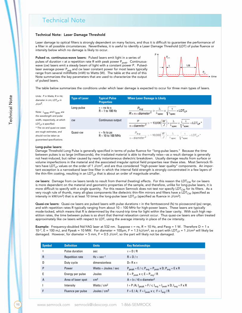
www.semrock.com [email protected] 1-866-SEMROCK
Technical Note
Tech
nica
l No
te
98
Symbol Definition Units Key Relationships
τ Pulse duration sec τ = D / R
R Repetition rate Hz = sec-1 R = D / τ
D Duty cycle dimensionless D= R x τ
P Power Watts = Joules / sec Ppeak = E / τ; Pavg = Ppeak x D; Pavg = E x R
E Energy per pulse Joules E = Ppeak x τ; E = Pavg / R
A Area of laser spot cm2 A = (π / 4) x diameter2
I Intensity Watts / cm2 I = P /A; Ipeak = F / τ; Iavg = Ipeak x D; Iavg = F x R
F Fluence per pulse Joules / cm2 F = E / A; F = Ipeak x τ; F = Iavg / R
Technical Note: Laser Damage Threshold
Laser damage to optical filters is strongly dependent on many factors, and thus it is difficult to guarantee the performance of a filter in all possible circumstances. Nevertheless, it is useful to identify a Laser Damage Threshold (LDT) of pulse fluence or intensity below which no damage is likely to occur.
Pulsed vs. continuous-wave lasers: Pulsed lasers emit light in a series of pulses of duration t at a repetition rate R with peak power Ppeak. Continuous-wave (cw) lasers emit a steady beam of light with a constant power P. Pulsed-laser average power Pavg and cw laser constant power for most lasers typically range from several milliWatts (mW) to Watts (W). The table at the end of this Note summarizes the key parameters that are used to characterize the output of pulsed lasers.
The table below summarizes the conditions under which laser damage is expected to occur for three main types of lasers.
Units: P in Watts; R in Hz;
diameter in cm; LDTLP in
J/cm2.
Note: lspec and tspec are
the wavelength and pulse
width, respectively, at which
LDTLP is specified.
* The cw and quasi-cw cases
are rough estimates, and
should not be taken as
guaranteed specifications.
Long-pulse lasers: Damage Threshold Long Pulse is generally specified in terms of pulse fluence for “long-pulse lasers.” Because the time between pulses is so large (milliseconds), the irradiated material is able to thermally relax—as a result damage is generally not heat-induced, but rather caused by nearly instantaneous dielectric breakdown. Usually damage results from surface or volume imperfections in the material and the associated irregular optical field properties near these sites. Most Semrock fil-ters have LDTLP values on the order of 1 J/cm2, and are thus considered “high-power laser quality” components. An impor-tant exception is a narrowband laser-line filter in which the internal field strength is strongly concentrated in a few layers of the thin-film coating, resulting in an LDTLP that is about an order of magnitude smaller.
cw lasers: Damage from cw lasers tends to result from thermal (heating) effects. For this reason the LDTCW for cw lasers is more dependent on the material and geometric properties of the sample, and therefore, unlike for long-pulse lasers, it is more difficult to specify with a single quantity. For this reason Semrock does not test nor specify LDTCW for its filters. As a very rough rule of thumb, many all-glass components like dielectric thin-film mirrors and filters have a LDTCW (specified as intensity in kW/cm2) that is at least 10 times the long-pulse laser LDTLP (specified as fluence in J/cm2).
Quasi-cw lasers: Quasi-cw lasers are pulsed lasers with pulse durations t in the femtosecond (fs) to picosecond (ps) range, and with repetition rates R typically ranging from about 10 – 100 MHz for high-power lasers. These lasers are typically mode-locked, which means that R is determined by the round-trip time for light within the laser cavity. With such high rep-etition rates, the time between pulses is so short that thermal relaxation cannot occur. Thus quasi-cw lasers are often treated approximately like cw lasers with respect to LDT, using the average intensity in place of the cw intensity.
Example: Frequency-doubled Nd:YAG laser at 532 nm. Suppose t = ns, R = 10 Hz, and Pavg = 1 W. Therefore D = 1 x 10⁻⁷, E = 100 mJ, and Ppeak = 10 MW. For diameter = 100μm, F = 1.3 kJ/cm2, so a part with LDTLP = 1 J/cm2 will likely be damaged. However, for diameter = 5 mm, F = 0.5 J/cm2, so the part will likely not be damaged.
time
PPpeak
1/R
Pavg
Type of Laser Typical Pulse Properties
When Laser Damage is Likely
Long-pulse t ~ ns to sR ~ 1 to 100 Hz
cw Continuous output
Quasi-cw t ~ fs to psR ~ 10 to 100 MHz
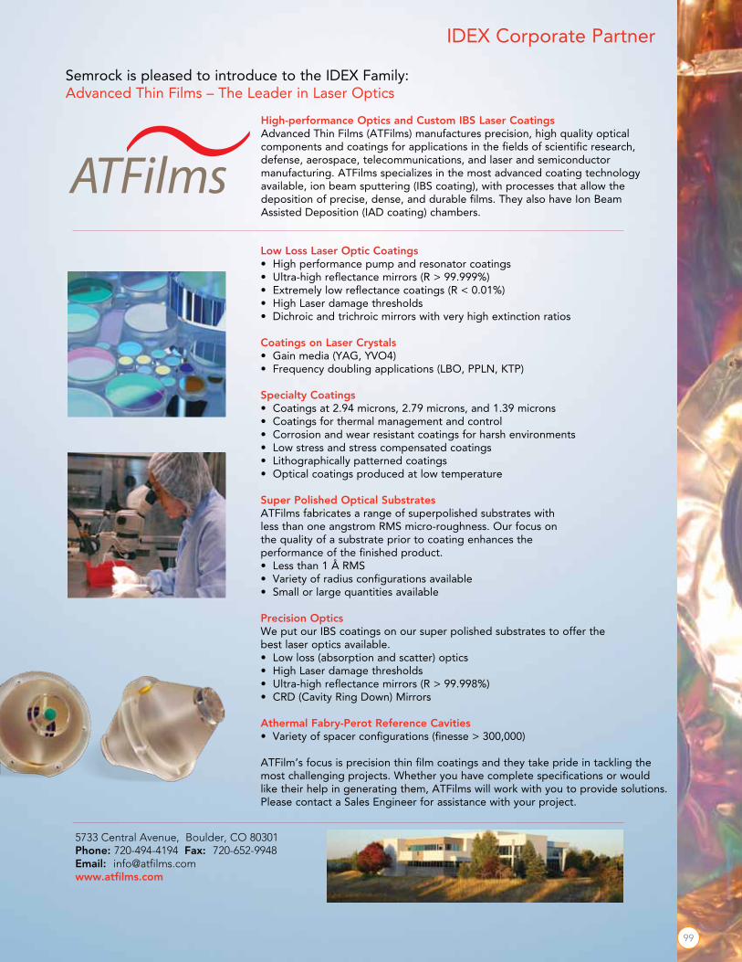
www.semrock.com [email protected] 1-866-SEMROCK
Semrock is pleased to introduce to the IDEX Family: Advanced Thin Films – The Leader in Laser Optics
High-performance Optics and Custom IBS Laser CoatingsAdvanced Thin Films (ATFilms) manufactures precision, high quality optical components and coatings for applications in the fields of scientific research, defense, aerospace, telecommunications, and laser and semiconductor manufacturing. ATFilms specializes in the most advanced coating technology available, ion beam sputtering (IBS coating), with processes that allow the deposition of precise, dense, and durable films. They also have Ion Beam Assisted Deposition (IAD coating) chambers.
IDEX Corporate Partner
5733 Central Avenue, Boulder, CO 80301Phone: 720-494-4194 Fax: 720-652-9948Email: [email protected]
Low Loss Laser Optic Coatings• High performance pump and resonator coatings • Ultra-high reflectance mirrors (R > 99.999%) • Extremely low reflectance coatings (R < 0.01%) • High Laser damage thresholds • Dichroic and trichroic mirrors with very high extinction ratios
Coatings on Laser Crystals• Gain media (YAG, YVO4)• Frequency doubling applications (LBO, PPLN, KTP)
Specialty Coatings• Coatings at 2.94 microns, 2.79 microns, and 1.39 microns • Coatings for thermal management and control • Corrosion and wear resistant coatings for harsh environments• Low stress and stress compensated coatings • Lithographically patterned coatings • Optical coatings produced at low temperature
Super Polished Optical SubstratesATFilms fabricates a range of superpolished substrates with less than one angstrom RMS micro-roughness. Our focus on the quality of a substrate prior to coating enhances the performance of the finished product.• Less than 1 Å RMS • Variety of radius configurations available • Small or large quantities available
Precision OpticsWe put our IBS coatings on our super polished substrates to offer the best laser optics available.• Low loss (absorption and scatter) optics• High Laser damage thresholds• Ultra-high reflectance mirrors (R > 99.998%) • CRD (Cavity Ring Down) Mirrors
Athermal Fabry-Perot Reference Cavities• Variety of spacer configurations (finesse > 300,000)
ATFilm’s focus is precision thin film coatings and they take pride in tackling the most challenging projects. Whether you have complete specifications or would like their help in generating them, ATFilms will work with you to provide solutions. Please contact a Sales Engineer for assistance with your project.
99
www.semrock.com [email protected] 1-866-SEMROCK
Optical Filters for Laser-basedFluorescence Microscopes
Flatness of Dichroic Beamsplitters Affects Focus & Image Quality
Super-resolution Microscopy
Lasers are increasingly and advanta-geously replacing broadband light sources for many fluorescence imaging applications. However, fluorescence applications based on lasers impose new constraints on imaging systems and their components. For example, optical filters used confocal and Total Internal Reflection Fluorescence (TIRF) microscopes have specific require-ments that are unique compared to those filters used in broadband light source based instruments.
Dichroic beamsplitters are now used as “image-splitting” elements for many applications, such as live-cell imaging and FRET, in which both the transmitted and reflected signals are imaged onto a camera. The optical quality of such dichroics is critical to achieving high-quality images, especially for the reflected light. If the beamsplitter is not sufficiently flat then significant optical aberrations may be introduced and the imaging may be severely compromised.
The latest incarnation of the modern fluorescence microscope has led to a paradigm shift. This wave is about breaking the diffraction limit first proposed in 1873 by Ernst Abbe and the implications of this development are profound. This new technology, called super-resolution microscopy, allows for the visualization of cellularsamples with a resolution similar to that of an electron microscope, yet it retains the advantages of an optical fluorescence microscope.
Semrock VersaChrome®
The First Widely Tunable Thin-film Optical Filters
Fluorescent Proteins: Theory, Applications and Best Practices
Spectral Imaging with VersaChrome®
Many optical systems can benefit from tunable filters with the spectral and two-dimensional imaging performance characteristics of thin-film filters and the center wavelength tuning speed and flexibility of a diffraction grating.
There are now dozens of fluorescent proteins that differ in spectral char-acteristics, environmental sensitivity, photostability, and other parameters. The history and development is dis-cussed, along with what they are and how they work. Applications of fluo-rescent proteins are covered, as are considerations for optical systems.
Spectral imaging with linear unmixing is necessary in multicolor fluorescence imaging when fluorophore spectra are highly overlapping. Tunable fluo-rescence filters now enable spectral imaging with all the advantages of thin-film filters, including high trans-mission with steep spectral edges and high out-of-band blocking.
Semrock White Paper Abstract LibraryFull downloadable versions are available on our website.
Five Year Warranty:Be confident in your filter purchase with our comprehensive five-year warranty. Built to preserve their high level of performance in test after test, year after year, our filters reduce your cost of ownership by eliminating the expense and uncertainty of replacement costs.
30 Day Return Policy:If you are not completely satisfied with your catalog purchase simply request an RMA number with our online form.
The completed form must be received by Semrock within 30 days from the date of shipment. Terms apply only to standard catalog products and sizes and returns totaling less than $3000. Returns must be received by Semrock within 10 business days of granting the RMA. All returns are subject to Semrock approval and a 25% restocking fee.
Rapid Custom-sizing Service:Semrock has refined its manufacturing process for small volumes of custom-sized parts to allow rapid turn-around. Most catalog items are available in a wide range of circular or rectangular custom sizes in less than one week. Please contact us directly to discuss your specific needs.
NEW NEW
Whi
te P
aper
Ab
stra
cts
100