the rf-flasher utility sw package - user manual
TRANSCRIPT
IntroductionThis document describes the RF-Flasher Utility SW package (STSW-BNRGFLASHER) which provides the Flasher Utility PCapplication.
The RF-Flasher Utility is a standalone PC application, which allows the BlueNRG-1, BlueNRG-2 and BlueNRG-LP Bluetooth lowenergy systems-on-chip Flash to be read, mass erased, written and programmed.
Besides, it currently supports interface to the BlueNRG-LP, BlueNRG-1, BlueNRG-2 Flash through UART mode using theinternal device UART bootloader. It also currently supports interface to the BlueNRG-LP, BlueNRG-1, BlueNRG-2 Flash throughSWD mode by using the standard SWD interface through standard HW programming/debugging tools (CMSIS-DAP, ST-Link/V2and J-Link).
Finally, it also allows a MAC address to be stored on a specific Flash location selected by the user on both UART and SWDmode.
The RF-Flasher SW package also provides a standalone flasher launcher utility which allows the flash programming, reading,mass erase and memory content verification. The flasher launcher utility requires a PC DOS window only.
Note: The RF term currently refers to the BlueNRG-LP, BlueNRG-1 and BlueNRG-2 devices. Any specific difference ishighlighted whenever it is needed.
The RF-Flasher utility SW package
UM2406
User manual
UM2406 - Rev 7 - October 2021For further information contact your local STMicroelectronics sales office.
www.st.com
1 Getting started
This section describes all system requirements to run the RF-Flasher Utility PC application, as well as the relativeSW package installation procedure.
1.1 System requirementsThe RF-Flasher Utility has the following minimum requirements:• PC with Intel® or AMD® processor running one of the following Microsoft® operating systems:
– Windows 10– Windows 7
• At least 128 MB of RAM• USB ports• 40 MB of free hard disk space• Adobe Acrobat Reader 6.0 or later
Note: Recommended display scale and settings are up to 125%
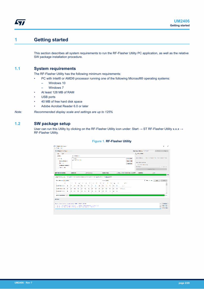
1.2 SW package setupUser can run this Utility by clicking on the RF-Flasher Utility icon under: Start → ST RF-Flasher Utility x.x.x →RF-Flasher Utility.
Figure 1. RF-Flasher Utility
UM2406Getting started
UM2406 - Rev 7 page 2/28
2 Toolbar interface
In the toolbar section of the RF-Flasher - Utility main window, user can perform the following operations:• Load an existing .bin or .hex (Intel extended) file (from File menu: open file.. option)• Save the current memory image in a .bin File (from File menu: save file as option). The start address and the
size of the memory section to be saved to file are selectable from the ‘Device Memory’ tab• Close an existing .bin or .hex file (from File menu: close file option)• Set ST Link frequency (from Tools menu: Settings... option)• Enable or disable log files creation in UART/SWD modality (from Tools menu: Settings... option). If log files
are saved, it is possible to set the level of debug information to save (for SWD only). All log files will besaved under path: {Installation Path}\ST\RF-Flasher Utility x.x.x\Logs\”
• Mass erase (from Tools menu: mass erase option)• Verify Flash content (from Tools menu: verify flash content option)• Get application version (from Help menu: about option)• Flash (from Tools menu: Flash option)• Erase device sectors (from Tools menu: Erase Pages...option)• Compare the device memory with the selected image file (from Tools menu: Compare Device Memory with
a file option). The two image files are displayed on "Compare Device Memory to File" tab and the relateddifferences are highlighted in red
• Compare two files (from Tools menu, Compare two files... option)• Read bootloader section (only SWD mode)• Read OTP area (only SWD mode)
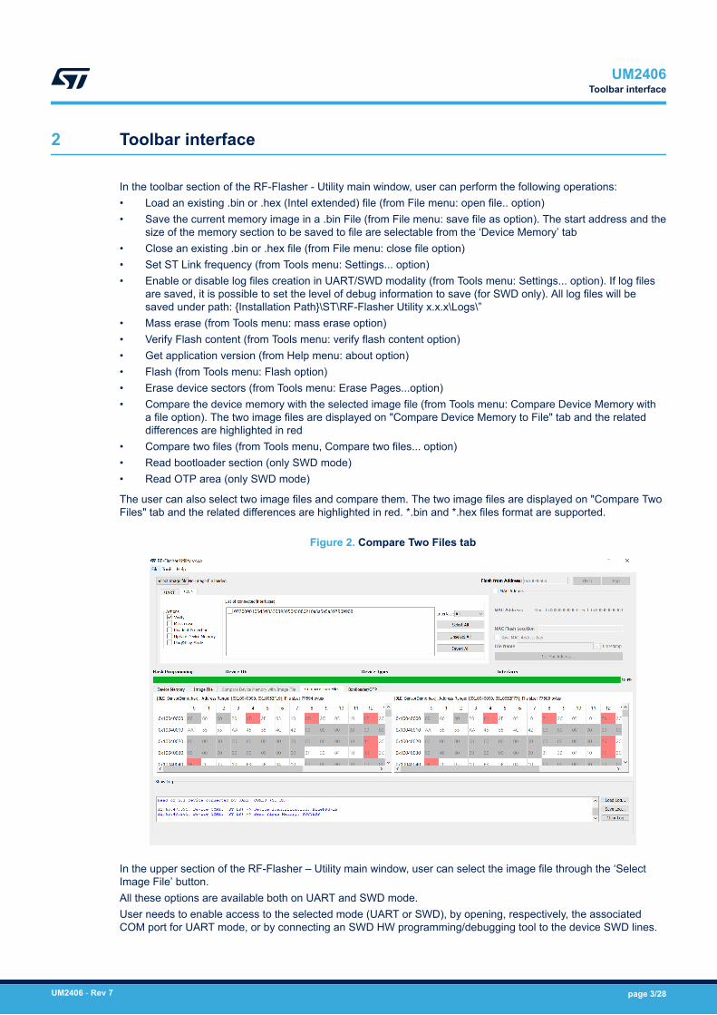
The user can also select two image files and compare them. The two image files are displayed on "Compare TwoFiles" tab and the related differences are highlighted in red. *.bin and *.hex files format are supported.
Figure 2. Compare Two Files tab
In the upper section of the RF-Flasher – Utility main window, user can select the image file through the ‘SelectImage File’ button.All these options are available both on UART and SWD mode.User needs to enable access to the selected mode (UART or SWD), by opening, respectively, the associatedCOM port for UART mode, or by connecting an SWD HW programming/debugging tool to the device SWD lines.
UM2406Toolbar interface
UM2406 - Rev 7 page 3/28

3 UART main window
In the UART main window tab of the RF-Flasher Utility main window, user can select the COM port to be used tointerface the device through the 'List of COM Ports' section.The serial baudrate used for the RF device evaluation board is 460800 bps.
Figure 3. Flasher Utility UART main window
3.1 UART mode: how to runImage file selectionUse the ‘Select Image File’ button on the main page (or the File> Open File... option or clicking on Image Filetab) to load an existing .bin or .hex file. The full path of the selected file appears next to the button and the ‘Flash’button becomes active at the end of file loading.The 'List of COM Ports' tab displays all the connected devices on PC USB ports. The 'Select All', Unselect All' and"Invert All' buttons allow to define which connected devices (all, none or some of them) should be the target of theutility operations. This allows to perform same operation (i.e. Flash programming) on multiple devices.By default, the ‘Mass erase’ option on "Actions" section is not checked, and only the required memory pages areerased and written with the file content. When this option is checked, the memory Flash phase is preceded by afull mass erase.The ‘Verify’ option forces a check to ensure that the memory content has been written correctly.Check the ‘Update Device Memory’ option to update the ‘Device Memory’ table after an operation on Flashmemory.The readout protection option enables the readout protection of the device after flash programming.Check the "Auto Baudrate' option only if an HW reset is performed on the board in order to force the 'AutoBaudrate' operation. By default, the 'Auto Baudrate' option is not checked.‘Image File’ tabThe selected file name, size and parsed contents to be flashed to the device memory can be viewed in the ‘ImageFile’ tab.
UM2406UART main window
UM2406 - Rev 7 page 4/28
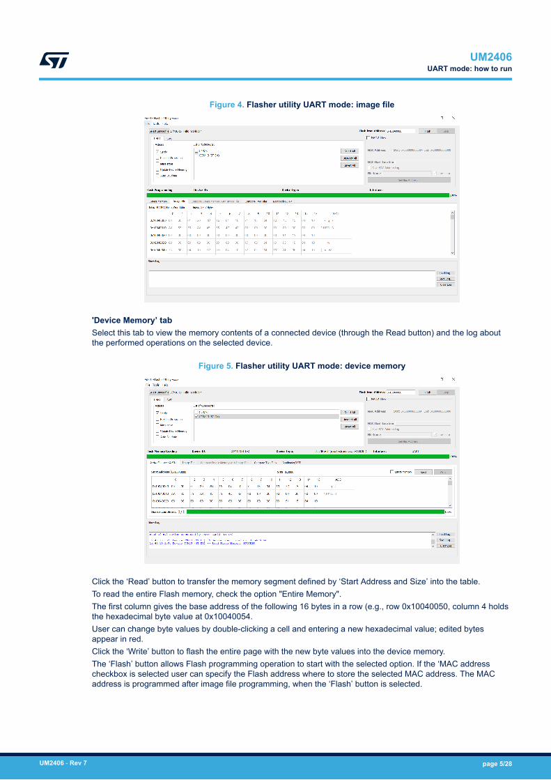
Figure 4. Flasher utility UART mode: image file
'Device Memory’ tabSelect this tab to view the memory contents of a connected device (through the Read button) and the log aboutthe performed operations on the selected device.
Figure 5. Flasher utility UART mode: device memory
Click the ‘Read’ button to transfer the memory segment defined by ‘Start Address and Size’ into the table.To read the entire Flash memory, check the option "Entire Memory".The first column gives the base address of the following 16 bytes in a row (e.g., row 0x10040050, column 4 holdsthe hexadecimal byte value at 0x10040054.User can change byte values by double-clicking a cell and entering a new hexadecimal value; edited bytesappear in red.Click the ‘Write’ button to flash the entire page with the new byte values into the device memory.The ‘Flash’ button allows Flash programming operation to start with the selected option. If the ‘MAC addresscheckbox is selected user can specify the Flash address where to store the selected MAC address. The MACaddress is programmed after image file programming, when the ‘Flash’ button is selected.
UM2406UART mode: how to run
UM2406 - Rev 7 page 5/28
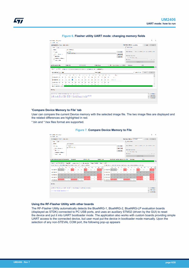
Figure 6. Flasher utility UART mode: changing memory fields
'Compare Device Memory to File’ tabUser can compare the current Device memory with the selected image file. The two image files are displayed andthe related differences are highlighted in red.*.bin and *.hex files format are supported.
Figure 7. Compare Device Memory to File
Using the RF-Flasher Utility with other boardsThe RF-Flasher Utility automatically detects the BlueNRG-1, BlueNRG-2, BlueNRG-LP evaluation boards(displayed as STDK) connected to PC USB ports, and uses an auxiliary STM32 (driven by the GUI) to resetthe device and put it into UART bootloader mode. The application also works with custom boards providing simpleUART access to the connected device, but user must put the device in bootloader mode manually. Upon theselection of any non-STEVAL COM port, the following pop-up appears
UM2406UART mode: how to run
UM2406 - Rev 7 page 6/28

Figure 8. Flasher Utility UART mode: UART ‘Comport Setting’ pop-up
When this pop-up appears, user must set the BlueNRG-LP pin PA10 high and perform a reset cycle of theBlueNRG-LP device (keeping the PA10 high) or must set the BlueNRG-1, BlueNRG-2 pin DIO7 high and reset theBlueNRG-1, BlueNRG-2 device (keeping the DIO7 high); the device should now be in bootloader mode.User can also set a preferred baudrate for the UART in the pop-up window and then press OK to return to theGUI.
Note: User must avoid resetting the device while using the RF-Flasher Utility unless the "ComPort Setting" pop-up isactive. If the device is reset, user must toggle the COM port to use the Flasher Utility again.
Note: When custom boards are used by providing UART access to the BlueNRG-1, BlueNRG-2, BlueNRG-LP devicesthrough a USB FTDI interface, user should double check the latency associated to the USB FTDI PC driverallowing the connected port as an USB Virtual COM to be recognized. On typical USB-FTDI PC driver, justdouble check the related device USB driver settings from Properties, Port Settings, Advanced and make surelatency timer value is set to 1 ms. This setting is strongly recommended in order to speed up the Flashoperations on custom boards.
UM2406UART mode: how to run
UM2406 - Rev 7 page 7/28
4 SWD main window
In order to use the SWD main window tab of the RF-Flasher Utility main window, user must connect SWD HWprogramming/debugging tool to the device SWD lines (BlueNRG-1, BlueNRG-2, BlueNRG-LP devices).The following SWD HW programming/debugging interfaces are supported, assuming that the selected HW andrelated SW tool supports the connected device:1. CMSIS-DAP2. ST-Link/V23. J-Link
Note: To use the J-Link as a debug adapter, the USB driver needs to be changed from the J-Link driver to WinUSB.This can be easily done by using the tool HYPERLINK Zadig ("https://zadig.akeo.ie/") as follows:• Select the J-Link from the device list, the "WinUSB" as driver and then click "Install Driver" to install the
WinUSB driver.• Refer to HYPERLINK JLink OpenOCD web page ("https://wiki.segger.com/OpenOCD") for more
information.• WARNING: Once the J-Link USB driver has been replaced, no SEGGER software from the J-Link software
package is able to communicate with J-Link anymore. To use SEGGER J-Link software again, the USBdriver needs to be switched back to its default.
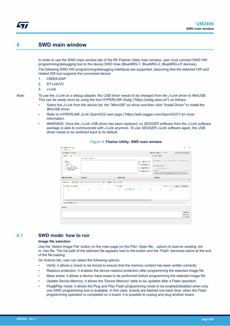
Figure 9. Flasher Utility: SWD main window
4.1 SWD mode: how to runImage file selectionUse the ‘Select Image File’ button on the main page (or the File> Open file... option) to load an existing .binor .hex file. The full path of the selected file appears next to the button and the ‘Flash’ becomes active at the endof the file loading.On Actions tab, user can select the following options:• Verify: it allows a check to be forced to ensure that the memory content has been written correctly• Readout protection: it enables the device readout protection after programming the selected image file• Mass erase: it allows a device mass erase to be performed before programming the selected image file• Update Device Memory: it allows the 'Device Memory' table to be updated after a Flash operation• Plug&Play mode: it allows the Plug and Play Flash programming mode to be enabled/disabled when only
one SWD programming tool is available. In this case, boards are flashed one each time: when the Flashprogramming operation is completed on a board, it is possible to unplug and plug another board.
UM2406SWD main window
UM2406 - Rev 7 page 8/28
By default, the ‘Mass erase’ option beside the ‘Flash’ button is not checked, and only the required memory pagesare erased and written with the file content.The ' List of connected interfaces' tab displays all the connected SWD interfaces (CMSIS-DAP, ST-Link/V2 andJ-Link).User can also select which specific SWD HW interface must be displayed through the 'Interface' field.The 'Select All', Unselect All' and "Invert All' buttons allow to define which connected SWD interfaces (all, noneor some of them) should be the target of the utility operations. This allows to perform same operation (i.e. Flashprogramming) on multiple devices.‘Flash’ button allows Flash programming operation to start with the selected option. If the ‘MAC address’checkbox is selected user can specify the Flash address where to store the selected MAC address. The MACaddress is programmed after image file programming, when the ‘Flash’ button is selected.‘Image File’ tabThe selected file name, size and parsed contents to be flashed to device memory can be viewed in the ‘ImageFile’ tab‘Device Memory’ tabSelect this tab to view the memory contents of a connected device and the log about the performed operationson the selected device. To view the memory contents of a connected device, it is necessary to select the 'Read'button on the "Device Memory" tab.
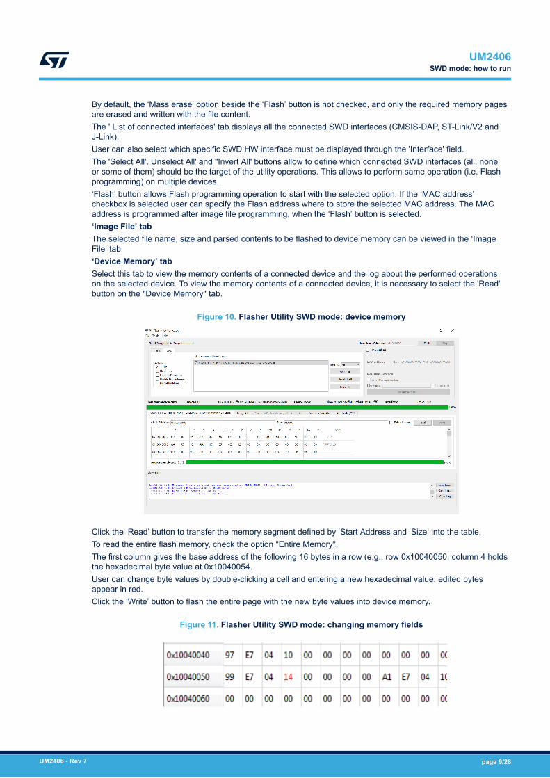
Figure 10. Flasher Utility SWD mode: device memory
Click the ‘Read’ button to transfer the memory segment defined by ‘Start Address and ‘Size’ into the table.To read the entire flash memory, check the option "Entire Memory".The first column gives the base address of the following 16 bytes in a row (e.g., row 0x10040050, column 4 holdsthe hexadecimal byte value at 0x10040054.User can change byte values by double-clicking a cell and entering a new hexadecimal value; edited bytesappear in red.Click the ‘Write’ button to flash the entire page with the new byte values into device memory.
Figure 11. Flasher Utility SWD mode: changing memory fields
UM2406SWD mode: how to run
UM2406 - Rev 7 page 9/28
Note: 'Compare Device Memory to File' is also supported on SWD mode with same features as described inSection 3.1 UART mode: how to run.
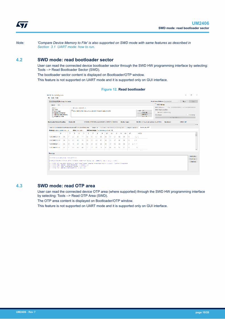
4.2 SWD mode: read bootloader sectorUser can read the connected device bootloader sector through the SWD HW programming interface by selecting:Tools --> Read Bootloader Sector (SWD).The bootloader sector content is displayed on Bootloader/OTP window.This feature is not supported on UART mode and it is supported only on GUI interface.
Figure 12. Read bootloader
4.3 SWD mode: read OTP areaUser can read the connected device OTP area (where supported) through the SWD HW programming interfaceby selecting: Tools --> Read OTP Area (SWD).The OTP area content is displayed on Bootloader/OTP window.This feature is not supported on UART mode and it is supported only on GUI interface.
UM2406SWD mode: read bootloader sector
UM2406 - Rev 7 page 10/28
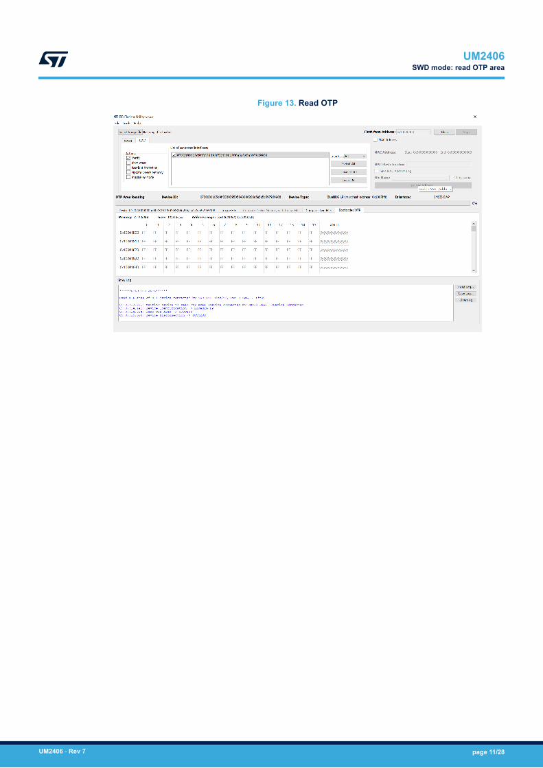
Figure 13. Read OTP
UM2406SWD mode: read OTP area
UM2406 - Rev 7 page 11/28
5 SWD Plug&Play programming mode
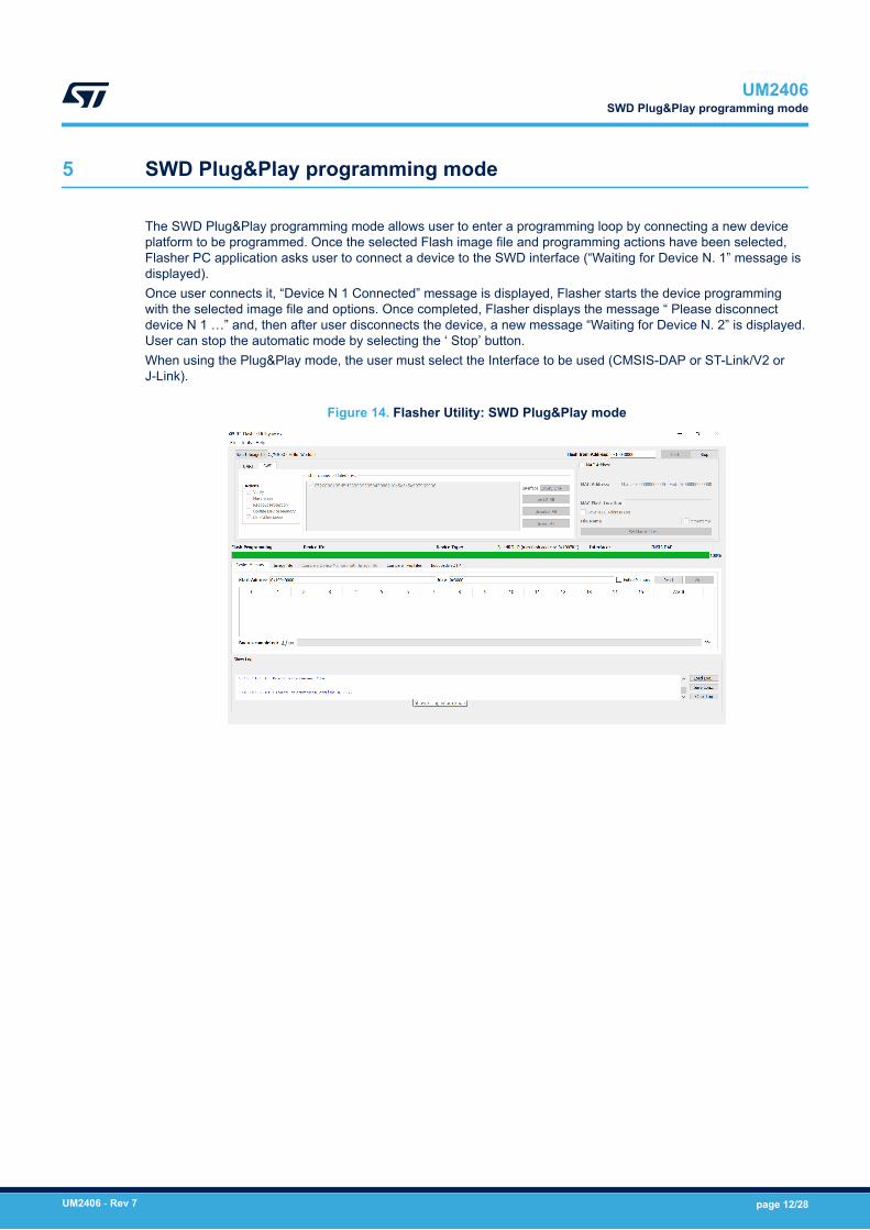
The SWD Plug&Play programming mode allows user to enter a programming loop by connecting a new deviceplatform to be programmed. Once the selected Flash image file and programming actions have been selected,Flasher PC application asks user to connect a device to the SWD interface (“Waiting for Device N. 1” message isdisplayed).Once user connects it, “Device N 1 Connected” message is displayed, Flasher starts the device programmingwith the selected image file and options. Once completed, Flasher displays the message “ Please disconnectdevice N 1 …” and, then after user disconnects the device, a new message “Waiting for Device N. 2” is displayed.User can stop the automatic mode by selecting the ‘ Stop’ button.When using the Plug&Play mode, the user must select the Interface to be used (CMSIS-DAP or ST-Link/V2 orJ-Link).
Figure 14. Flasher Utility: SWD Plug&Play mode
UM2406SWD Plug&Play programming mode
UM2406 - Rev 7 page 12/28

6 MAC address programming
MAC address programming section allows the MAC address and the specific device Flash location to be selectedto store MAC address.User can choose to enable on not the MAC address programming by selecting the ‘MAC address’ checkbox.Flash location is set through the ‘MAC Flash location’ field.‘Set MAC address’ button allows to select MAC address as follow:1. Check ‘Range’ and provide the ‘Start Address’ on related field: this is the MAC address to be stored on the
first connected device.– It is possible to set incremental steps starting from the ‘Start address’ value, by entering the number of
boards to be flashed on Num. Boards tab, or by entering the ‘End Address’ value:◦ If automatic mode has been selected on Actions tab, the selected MAC address list is used during
the automatic programming operations, otherwise only one device is programmed with the ‘StartAddress’ field.
2. User can provide the list of MAC addresses to be used through an input file:– Check ‘File’ and select the input text file through the ‘Load File’ field– If automatic mode has been selected on Actions tab, the selected MAC address list is used during the
automatic programming operations, otherwise only the first address is used for a single programmingoperation.
The ‘Save MAC Address log’ check box allows the list of used MAC addresses to be stored on a file enteredthrough the ‘File Name’ field.As already highlighted, MAC Address programming can be combined with the automatic programming mode. Foreach connected device, the image file is programmed followed by the MAC address programming. The numberof selected MAC addresses (incremental addresses list size or input file size) triggers the automatic programmingoperations end. Each programmed MAC address is displayed on the Log window.MAC address programming is supported on both UAR and SWD mode.
Figure 15. Flasher Utility: MAC address selection
UM2406MAC address programming
UM2406 - Rev 7 page 13/28
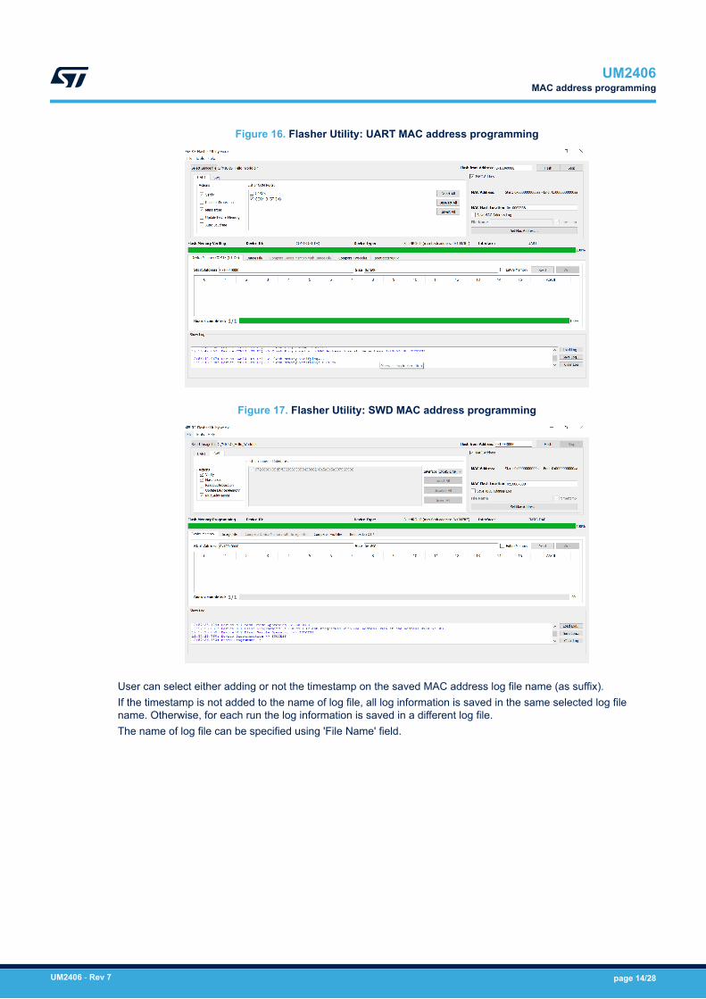
Figure 16. Flasher Utility: UART MAC address programming
Figure 17. Flasher Utility: SWD MAC address programming
User can select either adding or not the timestamp on the saved MAC address log file name (as suffix).If the timestamp is not added to the name of log file, all log information is saved in the same selected log filename. Otherwise, for each run the log information is saved in a different log file.The name of log file can be specified using 'File Name' field.
UM2406MAC address programming
UM2406 - Rev 7 page 14/28

7 RF-Flasher launcher utility
The RF-Flasher launcher is a standalone utility allowing the RF-Flasher Utility commands to be run without usingthe RF-Flasher Utility GUI tool.A DOS command window is required and both UART and SWD modes are supported (*.bin and *.hex imagefiles).The RF-Flasher launcher utility (RF-Flasher_Launcher.exe) is included on the RF-Flasher Utility softwarepackage within the folder "Application"."Release folder" on the RF-Flasher Utility SW package start menu (ST RF-Flasher Utility x.x.x) allows directaccess to the "Application" folder.
7.1 RequirementsIn order to use the RF-Flasher launcher utility on a specific device, the following prerequisites must be addressed:• UART mode: the BlueNRG-1, BlueNRG-2 and BlueNRG-LP platform must be connected to a PC USB port• SWD mode: an SWD HW programming/debugging tool must be connected to the BlueNRG-1, BlueNRG-2,
BlueNRG-LP SWD lines.
Note: Using the option -l, all operation steps are tracked in log files stored on "Logs" folder, which is created within theRF-Flasher Utility software package, "Application" folder.
7.2 RF-Flasher launcher utility optionsIn order to use the RF-Flasher launcher utility on a specific device, a Windows DOS shell must be opened anduser has to launch the related RF-Flasher_Launcher.exe with proper command and options (type –h to getthe list of all supported options):RF-Flasher_Launcher.exe -h:usage: RF-Flasher Launcher [-h] [-v]{flash,read,mass_erase,verify_memory,erase_pages,uart,swd}RF-Flasher Launcher version x.x.x.optional arguments:-h, --help show this help message and exit-v, --version show program's version number and exitcommands:{flash,read,mass_erase,verify_memory,erase_pages, uart, swd}flash: Programs a flash memoryread: Reads a flash memorymass_erase: Erases a flash memoryverify_memory Verifies the content of a BlueNRG-x device with a fileerase_pages Erase one or more pages from a Flash memoryuart: Shows all connected COM ports (UART mode)swd: Shows all devices connected by SWD interface: ST-LINK/V2, CMSIS-DAP, J-Link (SWD mode)
7.3 RF-Flasher launcher utility: UART, SWD modesThe RF-Flasher launcher utility supports two operating modes:• UART mode (just connect the selected device to a PC USB port)• SWD mode (just connect the selected BlueNRG-1, BlueNRG-2, BlueNRG-LP(1) device SWD lines to a SWD
programming/debugging tool.
1. It is natively available on the BlueNRG-LP, STEVAL-IDB01xVx kits. User must just connect the STEVAL kit to a PC USBport.
UM2406RF-Flasher launcher utility
UM2406 - Rev 7 page 15/28
RF-Flasher launcher utility: command uart for getting the list of all available COMx ports (which devices areconnected to the PC USB ports):RF-Flasher_Launcher.exe uartCONNECTED PORT = COM194 (ST DK), COM160 (ST DK)RF-Flasher launcher utility: command swd to get the list of all available connected SWD HW programming/debugging tools:RF-Flasher_Launcher.exe swdCONNECTED BY ST-Link/V2 = NO ST-Link/V2 CONNECTEDCONNECTED BY CMSIS-DAP (serial number of CMSIS-DAP interfaces):1) 07200001066fff333231545043084259a5a5a5a5979699082) 07200001066dff383930545043205830a5a5a5a5979699083) 07200001066dff333231545043084255a5a5a5a597969908CONNECTED BY J-Link = NO J-Link CONNECTED
7.4 RF-Flasher launcher utility: flash commandIn order to use the RF-Flasher launcher utility for programming a specific device flash memory, the flashcommand is available (type –h for getting the list of all supported options):>RF-Flasher_Launcher.exe flash -hflash command usage:RF-Flasher_Launcher.exe flash [-h] [-address START_ADDRESS][-f[FILE_BLUENRG_1,FILE_BLUENRG_2,FILE_BLUENRG_LP ][-erase] [-verify] [-rp] [-mac] [-mac_address MAC_ADDRESS][-mac_log_file MAC_LOG_FILE][-mac_start MAC_START_ADDRESS |-mac_file MAC_FILE_ADDRESS](-all | -d DEVICE_ID) [-verbose{1,2,3}] [-l](-UART | -SWD) [-frequency {5,15,25,50,100,125,240,480,900,1800,4000}]flash command optional arguments:• -h, –help Show this help message and exit• -address START_ADDRESS, –address START_ADDRESS Start Adress• -f [FILE_BLUENRG_1,FILE_BLUENRG_2, FILE_BLUENRG_LP], –fileToFlash
[FILE_BLUENRG_1,FILE_BLUENRG_2, FILE_BLUENRG_LP]File .bin or .hex to flash for the BlueNRG-1, BlueNRG-2, BlueNRG-LP devices
• -erase, –erase Enable Mass Erase option• -verify Enable Verify option• -rp, –readout_protection Enable ReadOut Protection option• -mac, –mac Enable Mac Address option• -all, --all All connected devices (COM port in UART mode; ST-Link/V2 ID, CMSIS-DAP ID, J-link ID in
SWD mode)• -d DEVICE_ID, --device DEVICE_ID. Set ID of HW tool used for the connection: COM port (UART
mode); ST-Link/V2 ID, CMSIS-DAP ID, J-Link ID (SWD mode)• -l, –log Log data• -UART, –uart UART mode. For custom board put it in bootloader mode (DIO7 high while performing a
reset cycle of the BlueNRG-1/2 or PA10 high while resetting device for BlueNRG-LP) before performing theoperation
• -SWD, –swd SWD mode• -mac_address MAC_ADDRESS Flash Location where storing the Bluetooth public address• -mac_log_file MAC_LOG_FILE, -ml MAC_LOG_FILE Files containing the log of stored/used MAC
Addresses and not stored/not used MAC addresses• -mac_start MAC_START_ADDRESS, -ms MAC_START_ADDRESS First MAC Address• -mac_file MAC_FILE_ADDRESS, -mf MAC_FILE_ADDRESS File containing the list of MAC addresses• frequency {5,15,25,50,100,125,240,480,900,1800,4000}, --frequency
{5,15,25,50,100,125,240,480,900,1800,4000} Set frequency value (only for SWD modality)
UM2406RF-Flasher launcher utility: flash command
UM2406 - Rev 7 page 16/28

• verbose {1,2,3}, --verbose {1,2,3} Increase output verbosity, set debug level to 3 (only for SWDmodality and log data)
Note: 1. If UART mode is selected, the device must be connected to a PC USB COM port and the –UART optionmust be used. If more than one device is connected to PC USB ports, the –all option allows all of themto be selected or user must specify each COM port with the –d option.
2. If SWD mode is selected, SWD HW programming/debugging tool must be connected to the selecteddevice SWD lines and it is necessary to specify the -swd option. If more than one device is connected toPC by SWD interface, the –all option allows all of them to be selected or user must specify each interfacewith the –d option.
3. The binary file to be loaded is specified with –f option. If user must program the BlueNRG-1, BlueNRG-2and BlueNRG-LP devices with related different binary files, on same programming session, the user canspecify the related binary images following this order: the BlueNRG-1, BlueNRG-2, BlueNRG-LP.RF-Flasher_Launcher.exe flash -UART -all-f "C:\{user_path}\BlueNRG-1_2 DK3.2.2\Firmware\BlueNRG1_Periph_Examples\Micro\Hello_World\BlueNRG-1\Micro_Hello_World.bin"-f "C:\{user_path}\BlueNRG-1_2 DK3.2.2\Firmware\BlueNRG1_Periph_Examples\Micro\Hello_World\BlueNRG-2\Micro_Hello_World.bin" –l-f "C:{user_path}\BlueNRG-LP DK 1.1.0\Firmware\Peripheral_Examples\Examples_MIX\MICRO\MICRO_Hello_World\Micro_Hello_World.bin"The first file is programmed on connected the BlueNRG-1 devices; the second file is programmed onconnected BlueNRG-2 devices, the third file is programmed on connected BlueNRG-LP devices
4. If –f option is not used, the binary images files specified on Application/config_file.conf are used:#Image file for BlueNRG_1 deviceBLUENRG_1 = “user_path”/bluenrg_1_binary_file.hex#Image file for BlueNRG_2 deviceBLUENRG_2 = “user_path”/bluenrg_2_binary.hex#Image file for BlueNRG_LP device BLUENRG_LP = “user_path”/bluenrg_lp_binary.hex
User must specify the full binary image path for each device.
7.5 RF-Flasher launcher utility: read commandIn order to use the RF-Flasher launcher utility for reading a specific device flash memory, the read command isavailable (type –h for getting the list of all supported option):RF-Flasher_Launcher.exe read –hread command usage:RF-Flasher_Launcher.exe read [-h] [-address START_ADDRESS][-size SIZE] [-s] (-all |-d DEVICE_ID)(-UART | -SWD) [-verbose{1,2,3}] [-l][-frequency {5,15,25,50,100,125,240,480,900,1800,4000}]
UM2406RF-Flasher launcher utility: read command
UM2406 - Rev 7 page 17/28
read command optional arguments:• -h, –help Show this help message and exit• -address START_ADDRESS, –address START_ADDRESS Start Address• -size SIZE, –size SIZE Size of memory flash to read• -s, –show Show the flash memory after a read operation• frequency {5,15,25,50,100,125,240,480,900,1800,4000}, --frequency
{5,15,25,50,100,125,240,480,900,1800,4000} Set frequency value (only for SWD modality)• -all, --all All connected devices (COM port in UART mode;ST-Link/V2 ID, CMSIS-DAP ID, J-Link ID in
SWD mode)• -d DEVICE_ID, --device DEVICE_ID. Set ID of HW tool used for the connection: COM port (UART
mode); ST-Link/V2 ID, CMSIS-DAP ID, J-Link ID (SWD mode)• -UART, –uart UART mode• -SWD, –swd SWD mode• -verbose Increase output verbosity (only for SWD mode and log data)• -l, –log Log data• -verbose {1,2,3}, --verbose {1,2,3} Increase output verbosity, set debug level to 3 (only for
SWD modality and log data)
Note: 1. If UART mode is selected, the device must be connected to a PC USB COM port and the –UART optionmust be used. If more than one device is connected to PC USB ports, the –all option allows all of themto be selected or user must specify each COM port with the –d option
2. If SWD mode is selected, an SWD HW programming/debugging tool must be connected to the selecteddevice SWD lines and it is necessary to specify the -swd option. If more than one device is connectedto PC by SWD interface, the –all option allows all of them to be selected or the user must specify eachinterface with the –d option.
7.6 RF-Flasher launcher utility: mass erase commandIn order to use the RF-Flasher launcher utility to perform a specific device flash mass erase, the mass_erasecommand is available (type –h to get the list of all supported options):RF-Flasher_Launcher.exe mass_erase –hmass_erase command usage:RF-Flasher_Launcher.exe mass_erase [-h] [-s] (-all | -d DEVICE_ID)(-UART | -SWD)[-verbose{1,2,3}] [-l][-frequency {5,15,25,50,100,125,240,480,900,1800,4000}]mass_erase command optional arguments:• -h, –help Show this help message and exit• -s, –show Show memory flash after a mass erase operation• -all, --all All connected devices (COM port in UART mode;ST-Link/V2 ID, CMSIS-DAP ID, J-Link ID in
SWD mode)• -d DEVICE_ID, --device DEVICE_ID. Set ID of HW tool used for the connection: COM port (UART
mode); ST-Link/V2 ID, CMSIS-DAP ID, J-Link ID (SWD mode)• -frequency {5,15,25,50,100,125,240,480,900,1800,4000}, --frequency
{5,15,25,50,100,125,240,480,900,1800,4000} Set frequency value (only for SWD modality)• -UART, –uart UART mode• -SWD, –swd SWD mode• -l, –log Log data• -verbose {1,2,3}, --verbose {1,2,3}Increase output verbosity, set debug level to 3 (for SWD
modality and log data only)
UM2406RF-Flasher launcher utility: mass erase command
UM2406 - Rev 7 page 18/28
Note: 1. If UART mode is selected, the device must be connected to a PC USB COM port and the –UART optionallows all of them to be selected. If more than one device is connected to PC USB ports, the –all optionmust be used or user must specify each COM port with the –d option.
2. If SWD mode is selected, an SWD HW programming/debugging tool must be connected to the selecteddevice SWD lines and it is necessary to specify the -swd option. If more than one device is connected toPC by SWD interface, the –all option allows all of them to be selected or user must specify each interfacewith the –d option.
7.7 RF-Flasher launcher utility: verify memory commandIn order to use the RF-Flasher launcher utility for verify a specific device flash memory content, theverify_memory command is available (type –h for getting the list of all supported option):RF-Flasher_Launcher.exe verify_memory –hverify_memory command usage:RF-Flasher_Launcher.exe verify_memory [-h] -f FLASH_VERIFY_FILE[-s][-addressSTART_ADDRESS](-all | -d DEVICE_ID) [-verbose{1,2,3}][-l] (-UART |-SWD)[-frequency{5,15,25,50,100,125,240,480,900,1800,4000}]verify_memory command optional arguments:• -h, –help Show this help message and exit• -f FLASH_VERIFY_FILE, –file FLASH_VERIFY_FILE File to use to verify flash memory• -s, –show Show memory flash after a verify operation• -address START_ADDRESS, –address START_ADDRESS Start Adress• -frequency {5,15,25,50,100,125,240,480,900,1800,4000}, --frequency
{5,15,25,50,100,125,240,480,900,1800,4000} Set frequency value (only for SWD modality)• -all, --all All connected devices (COM port in UART mode;ST-Link/V2 ID, CMSIS-DAP ID, J-Link ID in
SWD mode)• -d DEVICE_ID, --device DEVICE_ID. Set ID of HW tool used for the connection: COM port (UART
mode); ST-Link/V2 ID, CMSIS-DAP ID, J-Link ID (SWD mode)• -verbose {1,2,3}, --verbose {1,2,3} Increase output verbosity, set debug level to 3 (only for
SWD modality and log data)• -l, –log Log data in a txt file• -UART, –uart UART mode• -SWD, –swd SWD mode
Note: 1. If UART mode is selected, the device must be connected to a PC USB COM port and the –UART optionmust be used. If more than one device is connected to PC USB ports, the –all option allows all of themto be selected or user must specify each COM port with the –d option.
2. If SWD mode is selected, an SWD HW programming/debugging tool must be connected to the selecteddevice SWD lines and it is necessary to specify the -swd option. If more than one device is connected toPC by SWD interface, the –all option allows all of them to be selected or user must specify each interfacewith the –d option.
7.8 RF-Flasher launcher utility: erase pages commandIn order to use the RF-Flasher launcher utility for erase a specific device flash memory content page, theerase_pages command is available (type –h for getting the list of all supported option):RF-Flasher_Launcher.exe erase_pages –herase_pages command usage:RF-Flasher_Launcher.exe erase_pages [-h](-UART |-SWD)(-all | -d DEVICE_ID) [-l] [-verbose {1,2,3}] [-frequency{5,15,25,50,100,125,240,480,900,1800,4000}] [-s] -p pageserase_pages command optional arguments:• -h, –help Show this help message and exit• -UART, –uart UART mode
UM2406RF-Flasher launcher utility: verify memory command
UM2406 - Rev 7 page 19/28
• -SWD, –swd SWD mode• -all, --all All connected devices (COM port in UART mode;STlink/V2 ID, CMSIS-DAP ID, Jlink ID in
SWD mode)• -d DEVICE_ID, --device DEVICE_ID Set ID of HW tool used for the connection: COM port (UART
mode); STlink/V2 ID, CMSIS-DAP ID, Jlink ID (SWD mode)• -l, –log Log data in a txt file• -verbose {1,2,3}, --verbose {1,2,3} Increase output verbosity, set debug level to 3 (only for
SWD modality and log data)• -frequency {5,15,25,50,100,125,240,480,900,1800,4000}, --frequency
{5,15,25,50,100,125,240,480,900,1800,4000} Set frequency value (only for SWD modality)• -s, –show Show memory flash after a erase_pages operation• -p PAGES, --page PAGES List of pages to erase (it starts from 0)
Note: 1. If UART mode is selected, the device must be connected to a PC USB COM port and the –UART optionmust be used. If more than one device is connected to PC USB ports, the –all option allows all of them tobe selected or user must specify each COM port with the –d option.
2. If SWD mode is selected, an SWD HW programming/debugging tool must be connected to the selecteddevice SWD lines and it is necessary to specify the -swd option. If more than one device is connected toPC by SWD interface, the –all option allows all of them to be selected or user must specify each interfacewith the –d option.
UM2406RF-Flasher launcher utility: erase pages command
UM2406 - Rev 7 page 20/28
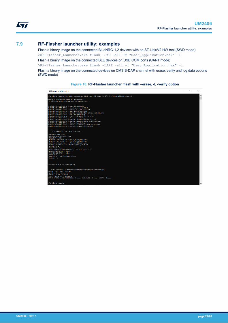
7.9 RF-Flasher launcher utility: examplesFlash a binary image on the connected BlueNRG-1,2 devices with an ST-Link/V2 HW tool (SWD mode)>RF-Flasher_Launcher.exe flash -SWD -all -f "User_Application.hex" –lFlash a binary image on the connected BLE devices on USB COM ports (UART mode)>RF-Flasher_Launcher.exe flash -UART –all -f "User_Application.hex" –lFlash a binary image on the connected devices on CMSIS-DAP channel with erase, verify and log data options(SWD mode)
Figure 18. RF-Flasher launcher, flash with –erase, -l, -verify option
UM2406RF-Flasher launcher utility: examples
UM2406 - Rev 7 page 21/28

8 List of acronyms
Table 1. List of acronyms
Term Meaning
BLE Bluetooth low energy
HW Hardware
RF Radio frequency
SW Software
SWD Serial wire debug UART
UART Universal asynchronous receiver-transmitter
USB Universal series bus
UM2406List of acronyms
UM2406 - Rev 7 page 22/28

Appendix A References
Table 2. Reference
Name Title
BlueNRG-1 datasheet Programmable Bluetooth® Low Energy wireless SoC
BlueNRG-2 datasheet Programmable Bluetooth® Low Energy wireless SoC
STSW-BNRGFLASHER Databrief for the RF-Flasher SW package
BlueNRG-LP datasheet Programmable Bluetooth® Low Energy wireless SoC
UM2406References
UM2406 - Rev 7 page 23/28
Revision history
Table 3. Document revision history
Date Version Changes
15-May-2018 1 Initial release.
03-Jul-2018 2
Updated Figure 1. BlueNRG-1, BlueNRG-2 Flasher Utility, Figure 2. FlasherUtility UART main window, Figure 3. Flasher utility UART mode: image file ,Figure 4. Flasher utility UART mode: device memory , Figure 5. Flasherutility UART mode: changing memory fields, Figure 7. Flasher Utility: SWDmain window, Figure 8. Flasher Utility SWD mode: device memory , Figure10. Flasher Utility: SWD automatic mode, Figure 11. Flasher utility: UARTautomatic mode, Figure 12. Flasher utility: UART automatic programming iscompleted and Figure 13. Flasher Utility: SWD MAC address selection.
Minor text changes throughout the document.
26-Feb-2019 3Updated the Section Introduction and Section 3.1 UART mode: how to run.
Added Section 8 Flasher launcher utility and all its sub sections.
09-Apr-2019 4Added reference to "Application folder" in Section 7 RF-Flasher launcherutility.
Updated Section 7.4 RF-Flasher launcher utility: flash command.
14-Jul-2020 5
Changed BlueNRG-1 and BlueNRG-2 to BlueNRG-X Flasher SW package
Added reference to BlueNRG-LP device.
Updated Figure 1. RF-Flasher Utility, Figure 3. Flasher Utility UARTmain window, Figure 5. Flasher utility UART mode: device memory ,Figure 6. Flasher utility UART mode: changing memory fields,Figure 9. Flasher Utility: SWD main window, Figure 10. Flasher Utility SWDmode: device memory , Figure 14. Flasher Utility: SWD Plug&Play mode,Figure 15. Flasher Utility: MAC address selection and Figure 18. RF-Flasherlauncher, flash with –erase, -l, -verify option
05-Dec-2020 6
Updated Section Introduction, Section 1.1 System requirements,Section 3.1 UART mode: how to run, Section 4 SWD mainwindow,Section 4.1 SWD mode: how to run, Section 7.1 Requirements,Section 7.2 RF-Flasher launcher utility options, Section 7.3 RF-Flasherlauncher utility: UART, SWD modes, Section 7.4 RF-Flasher launcherutility: flash command, Section 7.5 RF-Flasher launcher utility: readcommand, Section 7.6 RF-Flasher launcher utility: mass erase command,Section 7.7 RF-Flasher launcher utility: verify memory command.
Added Section 7.8 RF-Flasher launcher utility: erase pages command.
04-Oct-2021 7
Added Section 4.2 SWD mode: read bootloader sector andSection 4.3 SWD mode: read OTP area.
Updated the title, Section Introduction, Section 1 Getting started,Section 1.1 System requirements, Section 1.2 SW package setup,Section 2 Toolbar interface, Section 3 UART main window, Section 7 RF-Flasher launcher utility, Section 7.1 Requirements, Section 7.2 RF-Flasherlauncher utility options, Section 7.3 RF-Flasher launcher utility: UART,SWD modes, Section 7.4 RF-Flasher launcher utility: flash command,Section 7.5 RF-Flasher launcher utility: read command, Section 7.6 RF-Flasher launcher utility: mass erase command, Section 7.7 RF-Flasherlauncher utility: verify memory command, Section 7.8 RF-Flasherlauncher utility: erase pages command, Section 8 List of acronyms andSection Appendix A References.
UM2406
UM2406 - Rev 7 page 24/28

Date Version ChangesUpdated Figure 1. RF-Flasher Utility, Figure 2. Compare Two Filestab, Figure 3. Flasher Utility UART main window, Figure 4. Flasherutility UART mode: image file , Figure 5. Flasher utility UART mode:device memory , Figure 6. Flasher utility UART mode: changing memoryfields, Figure 7. Compare Device Memory to File, Figure 9. FlasherUtility: SWD main window, Figure 10. Flasher Utility SWD mode:device memory , Figure 16. Flasher Utility: UART MAC addressprogramming, Figure 17. Flasher Utility: SWD MAC address programming andFigure 18. RF-Flasher launcher, flash with –erase, -l, -verify option.
UM2406
UM2406 - Rev 7 page 25/28

Contents
1 Getting started . . . . . . . . . . . . . . . . . . . . . . . . . . . . . . . . . . . . . . . . . . . . . . . . . . . . . . . . . . . . . . . . . . . .2
1.1 System requirements . . . . . . . . . . . . . . . . . . . . . . . . . . . . . . . . . . . . . . . . . . . . . . . . . . . . . . . . . . . 2
1.2 SW package setup . . . . . . . . . . . . . . . . . . . . . . . . . . . . . . . . . . . . . . . . . . . . . . . . . . . . . . . . . . . . . 2
2 Toolbar interface . . . . . . . . . . . . . . . . . . . . . . . . . . . . . . . . . . . . . . . . . . . . . . . . . . . . . . . . . . . . . . . . . .3
3 UART main window. . . . . . . . . . . . . . . . . . . . . . . . . . . . . . . . . . . . . . . . . . . . . . . . . . . . . . . . . . . . . . . .4
3.1 UART mode: how to run. . . . . . . . . . . . . . . . . . . . . . . . . . . . . . . . . . . . . . . . . . . . . . . . . . . . . . . . . 4
4 SWD main window. . . . . . . . . . . . . . . . . . . . . . . . . . . . . . . . . . . . . . . . . . . . . . . . . . . . . . . . . . . . . . . . .8
4.1 SWD mode: how to run . . . . . . . . . . . . . . . . . . . . . . . . . . . . . . . . . . . . . . . . . . . . . . . . . . . . . . . . . 8
4.2 SWD mode: read bootloader sector . . . . . . . . . . . . . . . . . . . . . . . . . . . . . . . . . . . . . . . . . . . . . . 10
4.3 SWD mode: read OTP area. . . . . . . . . . . . . . . . . . . . . . . . . . . . . . . . . . . . . . . . . . . . . . . . . . . . . 10
5 SW automatic programming mode . . . . . . . . . . . . . . . . . . . . . . . . . . . . . . . . . . . . . . . . . . . . . . . .12
6 MAC address programming. . . . . . . . . . . . . . . . . . . . . . . . . . . . . . . . . . . . . . . . . . . . . . . . . . . . . . .13
7 RF-Flasher launcher utility . . . . . . . . . . . . . . . . . . . . . . . . . . . . . . . . . . . . . . . . . . . . . . . . . . . . . . . .15
7.1 Requirements . . . . . . . . . . . . . . . . . . . . . . . . . . . . . . . . . . . . . . . . . . . . . . . . . . . . . . . . . . . . . . . . 15
7.2 RF-Flasher launcher utility options . . . . . . . . . . . . . . . . . . . . . . . . . . . . . . . . . . . . . . . . . . . . . . . 15
7.3 RF-Flasher launcher utility: UART, SWD modes . . . . . . . . . . . . . . . . . . . . . . . . . . . . . . . . . . . . 15
7.4 RF-Flasher launcher utility: flash command. . . . . . . . . . . . . . . . . . . . . . . . . . . . . . . . . . . . . . . . 16
7.5 RF-Flasher launcher utility: read command . . . . . . . . . . . . . . . . . . . . . . . . . . . . . . . . . . . . . . . . 17
7.6 RF-Flasher launcher utility: mass erase command. . . . . . . . . . . . . . . . . . . . . . . . . . . . . . . . . . 18
7.7 RF-Flasher launcher utility: verify memory command. . . . . . . . . . . . . . . . . . . . . . . . . . . . . . . . 19
7.8 RF-Flasher launcher utility: erase pages command . . . . . . . . . . . . . . . . . . . . . . . . . . . . . . . . . 19
7.9 RF-Flasher launcher utility: examples . . . . . . . . . . . . . . . . . . . . . . . . . . . . . . . . . . . . . . . . . . . . 21
8 List of acronyms. . . . . . . . . . . . . . . . . . . . . . . . . . . . . . . . . . . . . . . . . . . . . . . . . . . . . . . . . . . . . . . . . .22
Appendix A References . . . . . . . . . . . . . . . . . . . . . . . . . . . . . . . . . . . . . . . . . . . . . . . . . . . . . . . . . . . . . .23
Revision history . . . . . . . . . . . . . . . . . . . . . . . . . . . . . . . . . . . . . . . . . . . . . . . . . . . . . . . . . . . . . . . . . . . . . . .24
UM2406Contents
UM2406 - Rev 7 page 26/28

List of figuresFigure 1. RF-Flasher Utility . . . . . . . . . . . . . . . . . . . . . . . . . . . . . . . . . . . . . . . . . . . . . . . . . . . . . . . . . . . . . . . . . . 2Figure 2. Compare Two Files tab . . . . . . . . . . . . . . . . . . . . . . . . . . . . . . . . . . . . . . . . . . . . . . . . . . . . . . . . . . . . . . 3Figure 3. Flasher Utility UART main window. . . . . . . . . . . . . . . . . . . . . . . . . . . . . . . . . . . . . . . . . . . . . . . . . . . . . . . 4Figure 4. Flasher utility UART mode: image file . . . . . . . . . . . . . . . . . . . . . . . . . . . . . . . . . . . . . . . . . . . . . . . . . . . . 5Figure 5. Flasher utility UART mode: device memory . . . . . . . . . . . . . . . . . . . . . . . . . . . . . . . . . . . . . . . . . . . . . . . . 5Figure 6. Flasher utility UART mode: changing memory fields . . . . . . . . . . . . . . . . . . . . . . . . . . . . . . . . . . . . . . . . . . 6Figure 7. Compare Device Memory to File . . . . . . . . . . . . . . . . . . . . . . . . . . . . . . . . . . . . . . . . . . . . . . . . . . . . . . . . 6Figure 8. Flasher Utility UART mode: UART ‘Comport Setting’ pop-up. . . . . . . . . . . . . . . . . . . . . . . . . . . . . . . . . . . . . 7Figure 9. Flasher Utility: SWD main window. . . . . . . . . . . . . . . . . . . . . . . . . . . . . . . . . . . . . . . . . . . . . . . . . . . . . . . 8Figure 10. Flasher Utility SWD mode: device memory . . . . . . . . . . . . . . . . . . . . . . . . . . . . . . . . . . . . . . . . . . . . . . . . 9Figure 11. Flasher Utility SWD mode: changing memory fields . . . . . . . . . . . . . . . . . . . . . . . . . . . . . . . . . . . . . . . . . . . 9Figure 12. Read bootloader . . . . . . . . . . . . . . . . . . . . . . . . . . . . . . . . . . . . . . . . . . . . . . . . . . . . . . . . . . . . . . . . . 10Figure 13. Read OTP . . . . . . . . . . . . . . . . . . . . . . . . . . . . . . . . . . . . . . . . . . . . . . . . . . . . . . . . . . . . . . . . . . . . . . 11Figure 14. Flasher Utility: SWD Plug&Play mode . . . . . . . . . . . . . . . . . . . . . . . . . . . . . . . . . . . . . . . . . . . . . . . . . . . 12Figure 15. Flasher Utility: MAC address selection. . . . . . . . . . . . . . . . . . . . . . . . . . . . . . . . . . . . . . . . . . . . . . . . . . . 13Figure 16. Flasher Utility: UART MAC address programming . . . . . . . . . . . . . . . . . . . . . . . . . . . . . . . . . . . . . . . . . . . 14Figure 17. Flasher Utility: SWD MAC address programming . . . . . . . . . . . . . . . . . . . . . . . . . . . . . . . . . . . . . . . . . . . 14Figure 18. RF-Flasher launcher, flash with –erase, -l, -verify option. . . . . . . . . . . . . . . . . . . . . . . . . . . . . . . . . . . . . . . 21
UM2406List of figures
UM2406 - Rev 7 page 27/28

IMPORTANT NOTICE – PLEASE READ CAREFULLY
STMicroelectronics NV and its subsidiaries (“ST”) reserve the right to make changes, corrections, enhancements, modifications, and improvements to STproducts and/or to this document at any time without notice. Purchasers should obtain the latest relevant information on ST products before placing orders. STproducts are sold pursuant to ST’s terms and conditions of sale in place at the time of order acknowledgement.
Purchasers are solely responsible for the choice, selection, and use of ST products and ST assumes no liability for application assistance or the design ofPurchasers’ products.
No license, express or implied, to any intellectual property right is granted by ST herein.
Resale of ST products with provisions different from the information set forth herein shall void any warranty granted by ST for such product.
ST and the ST logo are trademarks of ST. For additional information about ST trademarks, please refer to www.st.com/trademarks. All other product or servicenames are the property of their respective owners.
Information in this document supersedes and replaces information previously supplied in any prior versions of this document.
© 2021 STMicroelectronics – All rights reserved
UM2406
UM2406 - Rev 7 page 28/28