the quadruple mass filter: basic operating concepts · quadrupole mass analyzer for combined gas...
TRANSCRIPT

The Quadrupole Mass Filter: Basic Operating Concepts Philip E. Miller' and M. Bonner Denton University of Arizona, Tucson, AZ 85721
Quadrupole mass analyzers are now widely used in many areas of chemical analvsis. Althoueh nooularlv referred to as - . . quadrupole mass spectrometers, the mass-resolving proper- ties of such devices are reallv much more akin to those of a tunable variable handpass mass filter. Only ions within a narrow mass region (generally <I amu) are allowed to oass through the deiice. & electr&ically sweeping the position of the bandpass region, a quadrupole may be used to mimic the behavior of a mass spectrometer (see-~igure 1). Specifi- cally, the mass-resolving properties of quadrupoles result from an ion's intrinsic stability or instability within the device. In contrast, true mass spectrometers resolve ions hg dispersing ions in either space,-as in the case of a magnet& sector instrument (see Fig. 2), or in time, as in the case of a time-of-fliaht instrument (see Fie. 3).
~lthougK once considered by many to be only suitable for residual aas analvsis. todav auadruoole devices urobablv . . . produce more mass spectra than &y other typLof mass analyzer found in the chemical research or industrial labora- turs. High-performance quadrupole mass analyzers are now pruduced and mnrkrtrd by no less than a half dozen reoutn- ble manufacturers. ~ u r t h & , in applications where extr&nely high resolution data or exact mass measurements are not required, quadrupoles offer a number of significant advan- tages over more traditional mass analyzers.
The short distance between the ion source and the detec- tor (usually less than 15 cm) combined with the strong focus- ina orooerties of such devices make the auadruoole mass an&yzei useful a t comparatively high pressures 15 X 10-6 Torr). This feature has led to the widesuread use of the quadrupole mass analyzer for combined gas chromatogra- phy mass spectrometry (GC-MS) (I) and liquid chromato- graphy mass spectrometry (LC-MS) (2,3).
In contrast to magnetic and electric sector instrumenta- tion, quadrupoles resolve ions on the basis of their mass-to- charge ratio (mle), rather than on the basis of momentum or kinetic energy. Thus unit mass resolution may he preserved even when sampling ion populations which have wide veloci- ty distributions. This feature has proven to he useful in a number of practical situations including the coupling of the quadrupole mass analyzer with an inductively coupled plas- ma ion source (ICP-MS) (4, 5 ) , and the successive use of quadrupole mass analyzers as a method of performing mass spectrometry-mass spectrometry (MS-MS) experiments (6-8).
A third useful feature of the quadrupole mass analyzer is the mechanical simplicity of the instrument. Unlike many other types of mass analyzers, quadrupole devices do not rely on the use of magnetic fields for their mass-discriminat- ing properties. Thus the cost, bulk, weight, and slow scan speeds commonly associated with magnets are avoided. Fur- ther, the resolution of quadrupole devices is set electronical- ly, rather than mechanically, through the use of slits. These facts make quadrupole instrumentation ideal for remote, mobile, or unattended operation. Examples include the ad- aptation of auadrunole mass analvzers for mace flieht (9). - . . . and the use of vehicular-based quadrupole irkrumentation for real time environmental monitoring (10,Il).
' Present address: Lawrence Livermore National Laboratory, P.O. Box 808, Livermore, CA 94550.
Despite the widespread use of quadrupole mass analyzers in both academic and industrial laboratories, a notable void exists in the understanding of these important devices. Per- haps the single greatest obstacle to the widespread under- standing of such devices is the nature of the differential equations that govern the trajectory of particles within the device. In contrast to many other types of mass analyzers,
Figwe 1. Mass spectra are obtained by electronically sweeping the bandpass region along a mess axls.
I." 0.m
Figure 2. The magnetic sectw mass spectrometer disperses ions having different mass to charge ratio spatially.
Figure 3. The timwf-flight mass spectrometer disperses ions having different mars to charge ratios temporally (in time). .
Volume 63 Number 7 July 1986 617

Figure 4. Experimental configuration of a quadrupole mass analyzer.
I A B Figure 5.Operatlon of quadrupola in the x-z plane. a) lons are focused toward cemer axis when theelectrode potential is positive with respect tocenter axis. b) lons are defocused when eiecnode potential is negative with respect to center axis.
such as magnetic or electric sector instruments, ion cyclo- tron resonance spectrometers, and time-of-flight instrumeu- tation, the solutions to the differential equations that ulti- mately lead to the mass-resolving properties of quadrupoles are highly complex and difficult to treat analytically. Thus the operation of such devices is presented, particularly a t the undereraduate level. in a manner that is not easilv extended either-to the explkation of related devices, s&h as the quadrupole ion storage trap (QUISTOR)2 or the novel appli- cation of existing devices. Rather than visualizing the opera- tion of the quadrupole mass analyzer in terms of trajectory simulations derived from analytical theory, numerical inte- gration, or matrix calculations, it is suggested that alterna- tive semiquantitative approaches be utilized for the intro- duction of the novice to the theorv of the quadru~ole mass filter. The purpose of this manuscript is to introduce the educator to such an explanation (12-14), which is useful to the novice yet powerful enough to be extended to the opera- tion of related devices.
Physically the quadrupole mass analyzer consists of a set of four electrodes, ideally of hyperbolic cross section, that are accuratelv oositioned in a radial arrav. For oractical as " . well as economic reasons, most mass filters have employed electrodes of circular cross section (see Fie. 4) . Denison (15) has shown that the best approxim&.ion the ideal hyper: bolic field can be obtained if the radius of the circular elec- trodes (r) is related to the quadrupole field radius (ro) by the expression
Available commercially as a G C detector from Finnigan M A T Corp., 355 River Oaks Parkway, San Jose, CA.
618 Journal of Chemical Education
although the erroneous value of 1.16 still occasionally ap- pears in the literature.
Oualltative Descrlptlon of Quadrupole Operatlon
The filtering action of the quadrupole mass analyzer is obtained by the application of a combination of a time- independent (dc) and a time-dependent (ac) potential. The operation of a quadrupole mass filter is best visualized by considering the effect that the electrode structure and the applied potential have on the trajectory of achargedparticle in the X-Z and Y-Z planes se~aratelv. We will beein bv considering the effect that a time-dependent or ac poiential has on the trajectories of a beam of ions travelling in the X-Z plane. During a single period of the applied ac waveform, in the absence of a dc potential, the electrodes lviue alona the X axis spend 3/2 cyclk a t a positive potential and '72 cycleat a negative potential, relative to the center axis of the instru- ment. When the ac potential is positive with respect to the center axis, a beam of positive ions will be accelerated or focused onto the center axis of the electrode structure (see Fig. 5a). Conversely, when the applied potential is negative, a oositive beam of ions will be accelerated toward the neea- " tively hiased electrodes. That is, positively charged ions will be defocused awav from the center axis (see Fie. 5b). Wheth- er a particular ion will strike an electrode, and'thus be elimi- nated from the beam before i t reaches the detector, is a function of how long i t takes that ion to reach a negatively biased electrode. The specific dynamics of this process will he governed by a number of factors including the instanta- neous magnitude of the negative potential applied to the electrodes, the period of time during which the electrodes are held at a negative potential (e.g., the frequency of the ac waveform), as well as the position, velocity, and mass-to- charge ratio (mle) of the particle.
Let us now take into account the effect that results from adding a dc or time-independent term to the applied poten- tial. Specifically, a positive dc potential is applied to those electrodes that lie in the X-Z plane. Consider, in a qualita- tive sense, the mass-dependent effect that the combined dc and ac potentials will have on the trajectories of a collection of ions. If an ion is very heavy andlor the frequency of the ac potential is very rapi& an ion will tend only to feelthe effect of the average potential applied to the electrode structure. That is, heavy ions will tend only to be influenced by the positive dc potential. This means that such ions will be focused onto the center axis of the instrument. The small periods of time during which the electrodes are a t a negative notential will have a neelieible effect on the traiectories of " - heavy ions. In contrast, if an ion is very light, its path may be considerablv affected bv the r a ~ i d l v varvine ac ootential. If - . . - . in fact an ion is sufficiently light, it may experience a large enough acceleration, during a negative voltage excursion, to cause it to collide with an electrode and be discharged and pumped awav as a neutral species. That is, ions will he filtered on the basis of their mils.;-to-charge ratio. In particu- lar, iuns below some critical m r value will be filtered uut of the beam, owing to speed with which they can respond to the defocusing action provided by the negative portion of the ac notential. On the other hand. those ions havine a mass above ;he critical mle value will be transmitted throigh the device and on to the detector. Thus the electrode structure and the nature of the applied potential combine to form a high pass mass filter that operates in the X-Zplane (see Fig. 6).
Let us now discuss the nature of ion trajectories in the Y-Z plane. At any instant, the potential applied to the electrodes lying along the Y axis is equal in magnitude but opposite in sien to the potential applied to the electrodes that lie alone tce X axis. his meansthat the ac (RF) waveform applied to
the X electrodes is 180° out of phase with the potential herent in the operation of any quadrupole device can only be applied to the Y electrodes. More important, however, is the appreciated by a somewhat more quantitative description of fact that the dc ootential applied to the electrodes lvine in the device. the X-Z plane ispositive, while the dc potential appliez to electrodes lying in the Y-Z plane is negative. Again heavy ions will only tend to be influenced by the average value of the applied potential, that is, the dc potential. In this case, however, the dc potential is negative. This means that com- paratively heavy ions will tend to be eliminated from the ion beam owing to the defocusing effect caused by the negative dc potential. On the other hand, if an ion is sufficiently light, it mav resnond to the focusine action that results when the
The Equations of Motion Let us begin by describing the nature of the potential
(voltage) distribution that ionized particles encounter as they enter the mass analyzer. This description will depend upon two factors, a spatial factor that describes the shape of the electrode structure and a second factor that describes the time-dependent nature of the voltage applied to the electrode structure. For a sinusoidallv operated hwerbolic
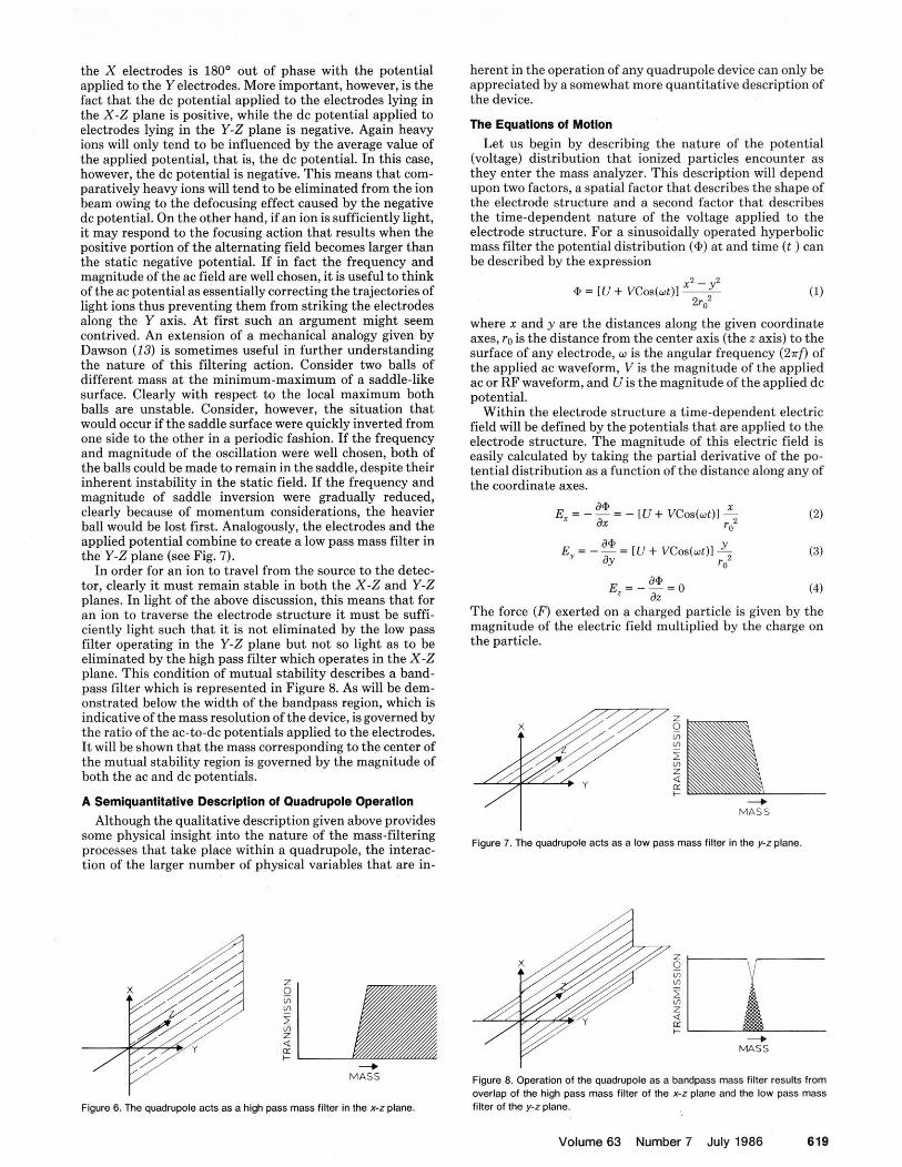
positrve of the alterna%ng field becomes larger than mass filter the potential distribution i*) i t and ti& ( t ) can the static neeative ootential. If in fact the freauencv and be described hv the expression magnitude oflthe ac 'field are well chosen, it is usekl tothink of the ac potentialas essentially correcting the trajectories of light ions thus preventing them from striking the electrodes along the Y axis. At first such an argument might seem contrived. An extension of a mechanical analogy given hy Dawson (13) is sometimes useful in further understanding the nature of this filtering action. Consider two halls of different mass a t the minimum-maximum of a saddle-like surface. Clearly with respect to the local maximum hoth balls are unstable. Consider, however, the situation that would occur if the saddle surface were quickly inverted from one side to the other in a periodic fashion. If the frequency and magnitude of the oscillation were well chosen, hoth of the balls could he made to remain in the saddle, despite their inherent instability in the static field. If the frequency and magnitude of saddle inversion were gradually reduced, clearly because of momentum considerations, the heavier ball would be lost first. Analogously, the electrodes and the applied potential combine to create a low pass mass filter in the Y-Z plane (see Fig. 7).
In order for an ion to travel from the source to the detec- tor, clearly it must remain stable in hoth the X-Z and Y-Z planes. In light of the above discussion, this means that for an ion to traverse the electrode structure i t must be suffi- ciently light such that i t is not eliminated by the low pass filter ooeratine in the Y-Z plane hut not so lieht as to be
where x and y are the distances along the given coordinate axes, ro is the distance from the center axis (the z axis) to the surface of any electrode, w is the angular frequency (2?rf) of the a~o l ied ac waveform. V is the maeuitude of the aoolied ac or RF waveform, and is the magnitude of the appiied dc potential.
Within the electrode structure a time-dependent electric field will be defined by the potentials that are applied to the electrode structure. The magnitude of this electric field is easily calculated by taking the partial derivative of the po- tential distribution as a function of the distance along any of the coordinate axes.
a* E, = - = [ U + V C o s ( o t ) l x JY
(3) r 2
a* E = - - = O ' Jz (4)
The force ( F ) exerted on a charged particle is given by the magnitude of the electric field multiplied by the charge on the particle.
eliminated by ;he high pass h e r which operate; in the X-Z plane. This condition of mutual stability describes a hand- pass filter which is represented in Figure 8. As will be dem- onstrated below the width of the bandpass region, which is indicative of themass resolution of the device, is governed by the ratio of the ac-to-dc potentials applied to the electrodes. I t will be shown that the mass corresponding to the center of the mutual stability region is governed by the magnitude of both the ac and dc potentials. Q
n + A Serniquanlitatlve Description of Quadrupole Operation 4
M A S S Although the qualitative description given above provides
some physical insight into the nature of the mass-filtering Figure ,, ihe acts as a low pass mass filter in the y.rplane processes that take place within a quadrupole, the interac- tion of the larger number of physical variables that are in-
,@ ii Z G VI VI - 5
1 5 Y)
LL Z +
4 2 MASS + + M A S S Figure 8. Operation of the quadrupale as a bandpass mass filter results from
overlap of the high pass mass filter of the x-.? plane and the low pass mass Figure 6. The quadrupole acts as a high pass mass filter in the x-z plane. filter of the y-z plane.
Volume 63 Number 7 July 1986 619

and
F, = 0
By Newton's law of F=ma, allows one to write d2u - + [a, + 2q,Cos2€]u = 0 d12
(22)
The Stablllty Diagram Equation 22 is in the canonical form of Mathieu's differen-
tial gquation, named for the French scholar E. Mathiru who intn~duced the use of such an equation in his 19th centurv
The solutions to these differential equations would give a complete description of the trajectory of any ion in terms of each ion's initial conditions. The solution to eq 10 is trivial; i t tells us that the position and velocity of an ion along the z axis remains unaffected by any potential applied to the electrode structure. Notice that the use of electrodes of hy- perbolic cross section leads to equations of motion that con- tain no cross-coordinate terms. That is, the motion of the particle remains independent along each of the three coordi- nate axes.
If we define the parameters a and q such that
discourse on the vibrational mod& of a stretched membrane having an elliptical boundary. Fortunately, an understand- ing of quadrupole devices does not require an extensive knowledge of such solutions. In fact, the generalized hehav- ior of the solutions of such differential equations is usually all that is needed to understand most of the salient features of quadrupole operation. In particular i t can he shown that solutions of this type of differential equation may he readily classified as being either bounded solutions or unbounded solutions. Physically, a bounded solution corresponds to a case where the displacement of the particle along either the Y or X axis remains finite. Ideally, in terms of the quadru- pole mass filter, such a case would correspond to a stable trajectory. That is, a particle entering the mass filter would be transmitted through the device and ultimately be regis- tered at the detector. In contrast, an unbounded solution corresponds to a case where the radial displacement of the particle would be expected to increase without bound. Solu- tions of this type correspond to particles which have unsta- ble trajectories. Such particles will he filtered out of the ion beam, due to collisions with the electrodes, before they can strike the detector. An extended analysis (16) of the perti- nent differential equations reveals that the stability of the appropriate solutions depend only upon the parameters a and q, which were defined above. This fact allows one to plot regions in a-q space where solutions to the equations of motion are stable or unstable (16).
The shaded region in Figure 9 represents a collection of points in a-q space that correspond to stable solutions of the
and
Then eqs 8 and 9 may be restated as
Equations 13 and 14 may be transformed into the canonical form of Mathieu's differential equation by the following change of variables
This implies that the quantity d2u/dt2 must be calculated where u represents either x (eq 13) or y (eq 14). By applica- tion of the chain rule
Thus the second derivative is given by
applying the product rule gives
By referring to eq 16 it is noted that
do ' & ' d 4 ' ds ' d.e ' qzLs&
rnr u Figure 9. The austabilitv dimram: a1 The shaded area reoresents those areas
Thus
. . i n b q space which correspond to stable solutions of k t h i e d s dllferential equation. b) The one am" bandpass mass filter: Notice that only ions of m/e m + 1 fall within the stability diagram. , Noting that
620 Journal of Chemical Education

equations of motion in hoth the X-Z plane and the Y-Z plane. In physical terms the stahility diagram allows the operation of the quadrupole mass filter to he reduced from a six-dimensional problem (involving e, w , ro, m, U, and V) to a two-dimensional problem involving only the reduced pa- rameters a and q. This results in a tremendous conceptual simplification that allows one to visualize readily the effect that changes in the various physical parameters will have on the operation of the quadrupole mass filter.
The Narrow Bandpass Mass Flller Historically, the most important use of the quadrupole
mass filter has been as a mass spectrometer. Recall that the quadrupole mass spectrometer is really a tunable mass filter capable of producing mass spectra. Such a distinction is particularly convenient in understanding the operation of such devices. In particular let us describe the operation of a narrow handpass mass filter in terms of the a-q stability diagram.
Figure 10. The variable bandpass mass filler: By adjusting the slope of the mass scan line, me bandpass reglon of the mass filter can be varied. The slope of the mars scan line is given by a/q = 2U/V.
RF Ydt .9 . A p p l i e d t. " El.ct.o*.,
4- conp,.*. u... sc.n-&
Figure 11. The nature ol the potential applied to the electrode structure during a scan. The magnitude of both the ac waveform and the dc voltage are increased while keeping their ratio constant.
In principle, one could operate a quadrupole in a manner in which the parameters a and q were, a t all times, indepen- dent of one another. That is, for any given mass a quadrupole could he operated a t any arbitrary point in a-q space. In practice, quadrupoles are usually operated in a manner such that the values of parameters a and q are always related by a simple ratio. Specifically, this condition is established by ensuring that the applied dc is always some fraction of the applied ac potential. That is, the ratio UIV is held constant, regardless of the actual magnitude of either Uor V. In terms of the a-q diagram, holding the ratio UIVconstant is equiva- lent to restricting operation of the mass filter to a set of ooeratine ooints which lie on a straight line which has a zero intercept: 'Such a line is known as the mass scan line (see Fig. 9). Since a and a contain a large number of common factors, the slope of themass scan line-(the quantity alp) is given hy the ratio 2UIV.
If, for a moment, one assumes that the values of the pa- rameters e, w, U, and V remain fixed, then a convenient conceptualization of the mass scan line is that of a number line which contains the mass of all particles. Recall, that mass (m) is inversely proportional to hoth a and q. Thus lighter particles (ions) will appear, along the mass scan line at the top right-hand portion of Figure 9, while heavier particles will appear on those portions of the mass scan line that are near the lower left-hand corner of Figure 9. Consider now if the slope of the mass scanline is suitably adjusted (by annrooriate adiustment of the UIV ratio) such that onlv a .. . small portion ot the mass scan line falls anywhere within the stahilitv diaeram (see Fie. 9h). Phvsicallv the situation illus- . . trated & ~ i i u r e 9b wouG result in ions bf only one mass (m + 1) heine able to oass throueh the electrode structure and on to the ietector. ~ h u s thescarp tip of thea-q diagram may he used to create a narrow bandoass mass filter. The hand- pass region of this filter (the res&tion) is easily changed by simply altering the slope of the mass scan line (changing the value of UlV). For example, if the ratio UIV is lowered, the resolution of the quadrupole would he reduced (see Fig. 10). Commercial quad~upole;nstrumentation is typically able to attain a resolution on the order of about 1 part in 1500.
The most convenient method of scannine the band~ass region of such a filter is by sweeping the vo&age app~ieh to the electrode structure. Consider if the voltaees Vand Uare - simultaneously increased, while keeping their ratio con- stant. clearlv the maenitude of the mass reoresented on the massscan lineat any particular coordinate inu-q space must also increase. !.'or example, if the magnitudes of both U and l'aresuddenly douhled, the mass (m) that appearsat thea-q coordinates that corresponds to the tip of the stability dia- gram must a190 double. Thus a voltage increase is equivalent tosliding the massscale shown in Figure9 upward and to the right along the maai. scan line. Sweeping the voltage applied to the electrode structure (see Fig. 1 1 ) thus provides a conve- nient method of scanning the hindpass region of the mass filter (see Fig. 1).
The RF-only Quadrupole Mass Filter The stability diagram is particularly powerful in that it
can easilv he extended to rationalize the behavior of nontra- ditional modes of quadrupole operation. The radio t'requen- cvonlv tRF-only) mudeof overatlon oro\.ides acase in pnint. The R F - O ~ I ~ mode of operation is achieved by the re&wal of the dc potential from the quadrupole electrode structure. In terms of the a-q stability diagram this is equivalent to operating the quadrupole under conditions where the Math- ieu parametera is always equal to zero. The mass scan line corresponding to the operation of an RF-only quadrupole device is re~resented hva line in a-a soace that has a slooe of zero and intercepts thea axis a t the doint a = 0. In contrast to the one amu bandoass mass filter. we find that a rather large portion of the mass scan line. fails within the stability
Volume 63 Number 7 July 1966 621

do ' dz ' d4 d6 ds ' q;=
m?2"?
Figure 12. The a-qdiagram representing t h e RF-only quadrupole m a s s anaiyz- er. Notice, in this example Ions having an m/eof 15 and 16 should have s tab le trajectories while ions having an m/e of 14 will be filtered out.
region of the a-q diagram. Thus a large number of ions having different mle values would be predicted to have sta- ble trajectories within the device. This fact has unfortunate- ly led to the popular misconception that RF-only quadru- poles are total ion transmission devices. Examination of the a-q stability diagram (Fig. 12) reveals in fact that such de- vices are high pass mass filters. In actual fact the situation is further complicated by certain focusing conditions, and by the fact that each m/e ion has a unique coordinate along the q axis (1 7).
For many years the RF-only mode of operation remained somewhat obscure. The develowment of trinle ouadru~ole mass spectrometry by Yost and Enke ( 6 4 hkprompted recent interest in such devices. RF-onlv auadruwoles have also heen utilized as a method of obtaining a"total ion chromatograph" in GC-MS (I) and function as part of a unique fast-scanning quadrupole device recently introduced commercially (18). Further, RF-only quadrupoles form the basis for a novel notch mass filter (19,20).
Concluslon The a-q stability diagram provides a powerful method of
visualizing the operation of the quadrupole mass filter, and the interaction of a numher of experimental variables. In addition to wrovidina the student with a hasis for under- standing themany d&erse operational modes of the quadru- pole mass filter, the stabilitv dianram also ~rovides the stu- dent with the basic concep&al tools needed to understand related instrumentation such as the monopole mass analyzer (see Fig. 13) and the quadrupole ion storage trap (QUIS- TOR) (see Fig. 14). I t is the authors' hope that the a-q stability diagram will be incorporated into the undergradu- ate instrumental analysis curriculum both to enlighten the interested student as well as to fight the widely held miscon- ception that quadrupole mass analyzers are complex and incomprehensible devices.
Acknowledgment This research was partially supported by the Office of
Naval Research.
Literature Cited (1) MeFadden, W. H. "TeehniquesofCombmd Gaschromafagraphy-M~specttttt-
Electrode
Entrance Figure 13. The monopole mass spectrometer.
Figure 14. The quadnrpoie ion s to rage trap (OUISTOR).
fry": Wiley-Intorscience: New York. 1973. (21 Amino,P.J.;Guichonn,G. And. Chem. I979,51,682A. (3) McFadden. W.H. J C h r o m Sci. 1980,18,97. (41 Date, A. R.; Gray, A. L. Spectrochem. Aefo 1983,38b, 29. (51 Houk, R. S.;Faosel, V. A.;Fl-h. G. D.;Svec.H. J.;Gray,A.L.;Taylor, C. E.Anol.
Chem. 1980,52.2263. (61 Yo8t.R.A.; Enkc,C.G. J .Amer Chsm.Soc. 1978.1W.2274. (71 YaaG R. A.: Enke,C.G.Anol. Cham. 1979.51.1251A. (61 Ym%R. A.; Enke,C.G. Amer.Lob. 1981.13,ffi. (91 Csrigan. G. A. In ''Quadropole MaanSpcctrometryand its Applicstians"; D a m n , P.
H., Ed. Elsevier: New York, 1976. (101 Thornson, B. A,; RobeM, J. R. Inter. J. Enuimn. A n d Chem. 1982,11,139. (11) Lane, D. A.; Thomson, B. A.J. Air Pollut. Control Assae. 1980,31,122. (12) Brubaker, W. 1n"instrumenuand Measurements: P r o d i n g s of the Fifth Interns-
tionel Instruments and Measurements Conferenee";Aeademie: New York, 1961. (13) Dawson, P. H."QuadrupoleMaaa Speetrometrysnd i u Applications";Elaevier: New
~ ~
York. 1976. (141 Lawson. G.:Todd, J . F.Chem.BriL. 1972,8,373. (15) Denison, D.R. J. Voc. Technol. 1971.8. 266. (16) Mdaehlan, D. W. "Theory and Applications of Mathieu Functions"; Clarendon:
Orford, 1947. (17) Miller, P. E.; Denton, M. B. manuscript in preparation. (18) Latuen, R. Kazmor (Hewlett-Paakard Co, 3W3 Scott Blud., Santa Clsra. CAI. per-
%anal communication. (19) Riensfelder, R. E.: Denton, M. B. hf. J. Moss Speck Ion Phya. 1981.37.241 (20) Reinsfelder, R. E. PhD dissertation, University of Arizona. 1976.
622 Journal of Chemical Education