the ps complex as proton pre-injector for the lhc – …cern.ch/blas/publications/2000-03.pdf ·...
TRANSCRIPT
CERN 2000-0327 February 2000
ORGANISATION EUROPÉENNE POUR LA RECHERCHE NUCLÉAIRE
CERN EUROPEAN ORGANIZATION FOR NUCLEAR RESEARCH
The PS Complex as Proton Pre-Injector for the LHC –Design and Implementation Report
M. Benedikt, A. Blas, J. Borburgh, R. Cappi, M. Chanel, V. Chohan, G. Daems, A. Fowler,R. Garoby, J. Gonzalez, D. Grier, J. Gruber, S. Hancock, C.E. Hill, A. Jansson, E. Jensen,A. Krusche, P. Maesen, K.D. Metzmacher, R. Losito, J. Olsfors, M. Paoluzzi, J. Pedersen,U. Raich, J.P. Riunaud, J.P. Royer, M. Sassowsky, K. Schindl, H. Schönauer, L. Sermeus,
M. Thivent, H. Ullrich, W. Van Cauter, F. Völker, M. Vretenar.
CERN, Geneva, Switzerland.
M. Barnes, E. Blackmore, F. Cifarelli, G. Clark, S. Koscielniak, F. Mammarella, A. Mitra,R. Poirier, K. Reiniger, T. Ries.
TRIUMF, Vancouver, Canada.
Editor: M. Benedikt
GENEVA
2000


i
CERN 2000-0327 February 2000
ORGANISATION EUROPÉENNE POUR LA RECHERCHE NUCLÉAIRE
CERN EUROPEAN ORGANIZATION FOR NUCLEAR RESEARCH
The PS Complex as Proton Pre-Injector for the LHC –Design and Implementation Report
M. Benedikt, A. Blas, J. Borburgh, R. Cappi, M. Chanel, V. Chohan, G. Daems, A. Fowler,R. Garoby, J. Gonzalez, D. Grier, J. Gruber, S. Hancock, C.E. Hill, A. Jansson, E. Jensen,A. Krusche, P. Maesen, K.D. Metzmacher, R. Losito, J. Olsfors, M. Paoluzzi, J. Pedersen,U. Raich, J.P. Riunaud, J.P. Royer, M. Sassowsky, K. Schindl, H. Schönauer, L. Sermeus,
M. Thivent, H. Ullrich, W. Van Cauter, F. Völker, M. Vretenar.
CERN, Geneva, Switzerland.
M. Barnes, E. Blackmore, F. Cifarelli, G. Clark, S. Koscielniak, F. Mammarella, A. Mitra,R. Poirier, K. Reiniger, T. Ries.
TRIUMF, Vancouver, Canada.
Editor: M. Benedikt
GENEVA
2000

ii

iii
ABSTRACT
The LHC will be supplied with protons from the pre-injector chaincomprising Linac2, PS Booster and PS. These accelerators have undergonea major upgrading programme during the last five years so as to meet thestringent requirements of the LHC. This implies that many high-intensitybunches of small emittance and tight spacing (25 ns) be available at the PSextraction energy (26 GeV/c). The upgrading project involved an increaseof Linac2 current, new RF systems in the PS Booster and the PS, raising thePS Booster energy from 1 to 1.4 GeV, two-batch filling of the PS, and theinstallation of high-resolution beam profile measurement devices. With theproject entering its final phase and most of the newly installed hardwarenow being operational, the emphasis switches to producing the nominalLHC beam and tackling the associated beam physics problems. This reportdescribes all the hardware changes related to the upgrading project.

iv

v
FOREWORD
The LHC will be supplied with protons through the existing PS / SPSinjector chain. In order to achieve the very special beam properties, a majorupgrade was needed, particularly in the PS complex, where hardwaremodifications were required in the Linac, Booster and in the PS itself. Thisupgrade project was started in 1995 and all major hardware modificationsare now complete and on schedule. The next phase of commissioning thebeam with the required properties for the LHC is well advanced.
This project has been carried out by the PS team with majorcontributions from colleagues at the TRIUMF laboratory in Canada. I wouldlike to thank them all and congratulate them for this first important steptowards obtaining luminosity in the LHC.
Lyn Evans (LHC Project Leader)

vi

vii
CONTENTS
FOREWORD.......................................................................................................................................... V
ABBREVIATIONS............................................................................................................................... IX
INTRODUCTION AND SUMMARY.................................................................................................... 1
1. BEAM REQUIREMENTS AND FUNDAMENTAL CHOICES................................................... 3
1.1 LHC AND SPS REQUIREMENTS ..................................................................................................................31.2 SCHEME TO PRODUCE THE LHC PROTON BEAM IN THE PS COMPLEX.........................................................51.3 OVERVIEW OF HARDWARE CHANGES, RECENT BEAM TESTS .......................................................................6
2. PROTON LINAC FOR LHC INJECTION ..................................................................................... 8
2.1 PROTON SOURCE OPTIMISATION .................................................................................................................92.2 REPLACEMENT OF THE COCKROFT-WALTON INJECTOR BY RFQ2 ..............................................................92.3 LINAC RF IMPROVEMENTS .........................................................................................................................92.4 BUNCH SHAPE MEASUREMENTS AND OPTIMISATION OF THE LINAC SETTING.............................................102.5 BEAM TRANSPORT TO THE PSB................................................................................................................102.6 LINAC2 PERFORMANCE ............................................................................................................................10
3. UPGRADING THE PSB TO 1.4 GEV – POWER SUPPLIES..................................................... 11
3.1 MAIN MAGNET POWER SUPPLY AND REACTIVE POWER COMPENSATOR.....................................................113.1.1 Topology of the upgraded main magnet supply.............................................................................113.1.2 The reactive power compensation .................................................................................................133.1.3 The power converter groups ..........................................................................................................133.1.4 Regulation and control electronics................................................................................................143.1.5 Quadrupole correction power supplies QFO and QDE ................................................................14
3.2 MAIN BENDING MAGNETS “TRIM” POWER SUPPLY ...................................................................................153.3 PSB-PS/ISOLDE BEAM-LINE POWER SUPPLIES .......................................................................................15
3.3.1 Requirements .................................................................................................................................153.3.2 Performance specification .............................................................................................................163.3.3 Technical solution..........................................................................................................................163.3.4 Project wind up..............................................................................................................................18
3.4 PULSED POWER CONVERTERS FOR THE SEPTUM MAGNETS IN THE TRANSFER LINE PSB-PS......................183.4.1 Operational requirements..............................................................................................................193.4.2 Pulsed capacitors discharge power converters .............................................................................193.4.3 Matching transformer and strip-line .............................................................................................193.4.4 Regulation and active filter ...........................................................................................................193.4.5 Characteristics of the power supplies............................................................................................19
4. UPGRADING THE PSB TO 1.4 GEV – OTHER SYSTEMS ..................................................... 20
4.1 PSB-PS LINE SEPTUM MAGNETS ..............................................................................................................204.1.1 Vacuum tanks.................................................................................................................................214.1.2 Magnets .........................................................................................................................................214.1.3 Displacement system......................................................................................................................224.1.4 Beam screen...................................................................................................................................224.1.5 Vacuum equipment ........................................................................................................................224.1.6 Calculations...................................................................................................................................224.1.7 Measurement results and conclusions ...........................................................................................23
4.2 PSB-PS TRANSFER LINE MAGNETS...........................................................................................................234.3 FAST KICKER SYSTEMS.............................................................................................................................26
4.3.1 PSB ejection BE.KFA14L1 and recombination kickers BT.KFA10 and BT.KFA20......................264.3.2 PSB ejection dipoles ......................................................................................................................284.3.3 PS injection and ejection kickers ...................................................................................................29
4.4 MORE POWERFUL WATER AND AIR COOLING SYSTEMS FOR THE PSB.....................................................29

viii
5. NEW RF HARMONICS TO ENABLE PS TWO-BATCH FILLING.......................................... 31
5.1 NEW PSB RF CAVITIES h=1 (0.6 – 1.8 MHZ) ..........................................................................................315.1.1 Cavity design .................................................................................................................................325.1.2 RF amplifier chain.........................................................................................................................335.1.3 System electronics layout...............................................................................................................33
5.2 CONVERTED PSB h=2 CAVITIES (1.2 – 3.9 MHZ) ....................................................................................335.3 PSB BEAM CONTROL MODIFICATIONS ......................................................................................................35
5.3.1 Hardware layout. ...........................................................................................................................355.3.2 The transition to h=1.....................................................................................................................36
5.4 PS BEAM CONTROL ..................................................................................................................................375.5 REPERCUSSIONS ON OTHER PS BEAMS .....................................................................................................38
6. NEW RF CAVITIES IN PS TO PRODUCE LHC BUNCH SPACING....................................... 39
6.1 DEBUNCHING, REBUNCHING AND BUNCH ROTATION IN THE PS................................................................396.1.1 Low-level RF..................................................................................................................................396.1.2 Beam dynamics ..............................................................................................................................40
6.2 40 MHZ AND 80 MHZ CAVITIES...............................................................................................................426.2.1 Requirements .................................................................................................................................426.2.2 Power considerations ....................................................................................................................426.2.3 Cavity geometry .............................................................................................................................436.2.4 Fast RF feedback ...........................................................................................................................446.2.5 Higher order mode damping .........................................................................................................446.2.6 Mechanical short circuit................................................................................................................456.2.7 Amplifier ........................................................................................................................................456.2.8 40 MHz: electric coupling .............................................................................................................466.2.9 80 MHz: magnetic coupling...........................................................................................................476.2.10 Tuner..............................................................................................................................................476.2.11 Parameters.....................................................................................................................................476.2.12 Overall system design ....................................................................................................................48
7. TRANSVERSE EMITTANCE CONSERVATION AND MEASUREMENT ............................ 49
7.1 EMITTANCE CONSERVATION ISSUES .........................................................................................................497.1.1 Transfer PSB to PS:.......................................................................................................................507.1.2 PS injection damper.......................................................................................................................517.1.3 Transfer PS to SPS: .......................................................................................................................51
7.2 BEAM DIAGNOSTIC UPGRADES IN VIEW OF LHC BEAMS ...........................................................................517.2.1 SEM-grids at PSB injection ...........................................................................................................517.2.2 The PSB fast wire scanners ...........................................................................................................527.2.3 The fast blade scanner ...................................................................................................................527.2.4 The PSB measurement line ............................................................................................................537.2.5 The PS measurement targets..........................................................................................................537.2.6 Non destructive profile measurement in the PS .............................................................................53
7.3 OTHER BEAM DIAGNOSTICS: NEW, IMPROVED, MODIFIED.........................................................................53
8. POSSIBLE FUTURE DEVELOPMENTS.................................................................................... 55
8.1 MEANS TO ACHIEVE THE SPECIFIED LONGITUDINAL BEAM PARAMETERS ..................................................558.1.1 Status of performance ....................................................................................................................558.1.2 Multiple splitting............................................................................................................................55
8.2 OTHER IMPROVEMENTS............................................................................................................................578.2.1 Bunching factor at low energy.......................................................................................................578.2.2 Special beam time structure for handling electron clouds in the LHC..........................................57
ACKNOWLEDGEMENTS .................................................................................................................. 57
APPENDIX: LIST OF RELEVANT PARAMETERS ........................................................................ 59
REFERENCES...................................................................................................................................... 61

ix
ABBREVIATIONS
AC Alternating Current
AD Antiproton Decelerator
ADC Analogue to Digital Converter
CAMAC Computer Automated Measurement And Control (IEEE standard)
DC Direct Current
DCBCT DC Beam Current Transformer
DCCT DC Current Transformer
DDS Direct Digital Synthesiser
DSC Device Stub Controller
DSP Digital Signal Processor
FODO Focusing lattice structure
HF High Frequency
HLM High Loss Mode
HOM Higher Order Mode
HV High Voltage
IGBT Insulated Gate Bipolar Transistor
LHC CERN Large Hadron Collider
Linac2 CERN 50 MeV proton linear accelerator
MD Machine Development
MP MultiPactor
PA Power Amplifier
PFN Pulse Forming Network
PLC Programmable Logic Controller
ppb protons per bunch
PPM Pulse to Pulse Modulation
ppp protons per pulse
PS CERN Proton Synchrotron
PSB CERN Proton Synchrotron Booster
QDE Defocusing quadrupole magnets of the PSB
QFO Focusing quadrupole magnets of the PSB
RF Radio Frequency
RFQ Radio Frequency Quadrupole
SEM Secondary Emission Monitor
SMPS Switch Mode Power Supply
SPS CERN Super Proton Synchrotron
TCR Thyristor Controlled Reactor
VME VERSAmodule Eurocard (industrial standard computer bus)

x

1
INTRODUCTION AND SUMMARY
CERN’s Large Hadron Collider (LHC) [1] will be supplied with protons from the injector chainLinac2 - Proton Synchrotron Booster (PSB) - Proton Synchrotron (PS) - Super Proton Synchrotron(SPS), shown in Fig. 1. These accelerators are in the process of being upgraded so as to meet the verystringent needs of the LHC: many high intensity proton bunches (2835 per LHC ring) with smalltransverse and well defined longitudinal emittances. The main challenges for the PS complex are (i)the unprecedented transverse beam brightness (intensity/emittance), almost twice the one the PS wasable to produce so far, and (ii) the production of bunches with the LHC spacing of 25 ns beforeextraction from the PS (26 GeV/c). A scheme was proposed [2] which implies new Radio Frequency(RF) harmonics in the PSB (1, 2) and PS (8, 16, 84), an increase of the PSB energy from 1 to1.4 GeV, and two-batch filling of the PS. After a successful (partial) test of the scheme’s mainingredients in 1993, a project of converting the PS complex for LHC was started in 1995 and itscompletion is scheduled for early 2000. Major parts of this project are (i) new h=1 RF systems in thePSB, (ii) upgrading of the PSB main magnet supply from 1 to 1.4 GeV operation, (iii) new magnets,septa, power supplies, kicker pulsers for the PSB-PS beam transfer, (iv) new 40 and 80 MHz RFsystems in the PS, (v) beam profile measurement devices with improved resolution. About onequarter of the project resources (funds, manpower) is provided by TRIUMF under the Canada-CERNCo-operation Agreement on the LHC.
Fig. 1 The LHC injector complex.
The SPS, LHC’s injector synchrotron, has to deal with two major issues: (i) maintaining thehigh-density bunches stable during acceleration, implying an elaborate programme for impedancereduction, (ii) keeping the transverse emittance blow-up within very tight tolerances. The upgradingof the SPS as LHC injector has been presented in a Design Report [3] and the project has beenlaunched recently. Yet, some of the basic decisions depend on studies still to be done with LHC-typebeams from the PS, which was the main reason to get the PS conversion started so much earlier.
An overview of the PS conversion as well as the beam dynamics issues involved are presentedin Chapter 1 together with older (1993) and more recent results of beam tests. Note that upgrading ofthe PS complex as a heavy ion pre-injector for LHC is not treated in this Design Report.
Measures to even further improve the proton beam intensity (aiming at 180 mA) and brilliancefrom Linac 2 are outlined in Chapter 2.
Increasing the beam energy of the PSB by 40 % (momentum by 26 %) to 1.4 GeV calls forrenewal or overhaul of several systems and components, such as the main magnet supply (includingtransformers and chokes), the PSB-PS 4-level recombination and transfer line magnets and their DCor pulsed power supplies, the pulsed magnetic septa and fast kicker pulsing systems, and the waterand air cooling system to tackle the increased power dissipation. Chapter 3 deals with the

2
new/upgraded power supply systems, whereas new magnets, septum magnets, kicker pulsers andwater cooling are discussed in Chapter 4.
Operating each of the four PSB rings with just one bunch opens up the way for PS two-batchfilling. The new h=1 and converted h=2 cavities as well as the digital beam control systems dealingwith the new harmonic numbers in PSB (h=1, 2) and PS (h=8, 16) are presented in Chapter 5, whichalso touches upon the repercussions of these changes on other operational beams of the complex.
Short (< 4 ns) bunches with 25 ns spacing are produced in the PS by fixed-frequency RFcavities (one at 40 MHz with 300 kV, and two at 80 MHz with 300 kV each) which have to withstandthe beam loading of much higher intensity beams without perturbing them. The cavities, their drivingsystems as well as the elaborate non-adiabatic procedure to achieve the short bunch length (includingresults of extensive beam tests) are dealt with in Chapter 6.
The LHC beam features transverse emittances which are unusually small and have to stay sothrough the injector chain. Small amounts of mis-steering and mismatch between the accelerators ofthe chain, virtually negligible for normal operation, are becoming increasingly important, and theireffect has to be measurable, calling for high-resolution beam profile monitors. Moreover, variousposition measurement systems are modified to deal with the new harmonics (rings) or to allow bunch-by-bunch observation (TT2). The new or modified diagnostic devices are summarised in Chapter 7which also deals with work on an injection oscillation damper for the PS.
Finally, Chapter 8 gives a glimpse of possible future developments which may avoid some ofthe difficulties which have already been identified in beam tests.
A comprehensive parameter list of the PS complex as LHC proton injector is compiled in theAppendix.

3
1. BEAM REQUIREMENTS AND FUNDAMENTAL CHOICES
1.1 LHC and SPS requirements
The figure of merit for colliders such as the LHC is the luminosity
βπεγ
=n
rev2bb
4
fNkL ,
with kb the number of bunches per ring, Nb the number of protons per bunch, f rev
the revolutionfrequency, εn the normalised rms transverse beam emittance (same in both planes), β the beta-function at the interaction point. L is proportional to the number of events per second and has thus tobe maximised. But more conditions are to be satisfied: (i) the beam emittance has to fit into the smallaperture of the superconducting LHC magnets; (ii) the total intensity kb
Nb is limited by the thermalenergy produced by synchrotron radiation which must be absorbed by the cryogenic system; (iii) thebeam-beam effect – proportional to the transverse beam brightness Nb/εn - causing a spread in betatrontunes (“footprint”) when the beams are colliding has to be kept below a certain limit; (iv) the space-charge limit in the injectors, which also scales with Nb/εn
. Conflicting requirements also determine thelongitudinal emittance εL
which has to be small at injection (small ∆p/p to ease beam transport fromthe SPS through the two ~2.5 km long lines), but large at collision to avoid transverse emittanceblow-up by intra-beam scattering.
An elaborate optimisation procedure, taking into account these boundary conditions, hasresulted in the LHC beam parameter set [1] compiled in Table 1. The “ultimate” performance levelcorresponds to the LHC beam-beam limit, whereas the “nominal” performance combines highluminosity with operational margin. Moreover, during the first year of physics running the LHC willbe operated at a much lower intensity and luminosity level (“initial”).
Table 1LHC nominal, ultimate, initial proton beam parameters.
Injection CollisionEnergy [GeV] 450 7000Luminosity nominal
ultimateinitial
[cm-2s-1] 1034
2.5 1034
1033
Number of bunches 2835 3564 bunch placesBunch spacing [ns] 24.95Nb intensity per bunch nominal
ultimateinitial
[p/b] 1.1 1011
1.7 1011
1.7 1010
Beam current nominal ultimate
initial
[A] 0.560.870.087
εn (transverse emittance, rms,normalised), nominal & ultimate
[µm] 3.6 3.75 Emittances equal in both planes.small blow-up allowed in LHC
εn (transverse emittance, rms,normalised), initial
[µm] 0.9 1.0
Longitudinal emittance, total [eVs] 1.0 2.5 Controlled blow-up during accel.Bunch length, total (4σ [ns] 1.7 1.0 has to fit into 400 MHz bucketsEnergy spread, total (4σ) [10-3] 1.9 0.45
Much like the PS complex, the SPS is an “old” machine and was not optimised for its futurefunction as LHC injector. The intensity the SPS is able to accelerate (~ 4 1013 protons/cycle,particularly difficult if concentrated on 3/11 of its circumference) limits the number of PS pulses per

4
SPS cycle to three. The momentum spread acceptance of the PS-SPS line (TT2, TT10) is about0.2 % in ∆p/p, while the total bunch length has to be below 4 ns to fit into the buckets of the SPS200 MHz accelerating system, that is a longitudinal emittance of 0.35 eVs per PS bunch. Owing tothe SPS’s large longitudinal broad-band impedance, such bunches are intrinsically unstable(longitudinal micro-wave instability) when injected: an SPS impedance reduction programme is inprogress. While the longitudinal emittance will be increased (hopefully in a controlled way) from0.35 to 1 eVs during SPS acceleration, there is little margin for (undesirable) transverse emittanceblow-up in this machine.
Table 2Beam characteristics at extraction from the PS.
Proton momentum [GeV/c] 26Number of PS batches to fill SPS 3 Limited by SPS peak intensityPS repetition time [s] 3.6 PS 2-batch filling from PSBNumber of bunches in PS 84 81 to SPS, 3 “killed” by extr. kickerBunch spacing [ns] 24.97Number of protons/bunch Nb – ultimate
nominalinitial
1.7 1011
1.1 1011
1.7 1010
Transverse normalised ultimate, nominalrms emittance εn initial
[µm] 3.00.8
Brightness Nb/εn of initial beamsmaller than nominal and ultimate
Bunch area (longitudinal emittance) εL [eVs] 0.35Bunch length (total) [ns] 4 Limited by SPS 200 MHz bucketsRelative momentum spread ∆p/p total (4σ) 0.004 Limited by TT2-TT10 acceptance
The LHC and SPS requirements define the beam characteristics at PS extraction (Table 2). Thefilling sequence PS-SPS-LHC is sketched in Fig. 2.
Fig. 2 Proton bunches in the PS, SPS and one LHC ring. Note the partial filling of the SPS (3/11)and the holes due to kicker rise-times. One LHC ring is filled in 3 min.
LHC (1-Ring) = 88.924 µs
SPS = 7/27 LHC
PS = 1/11 SPS
81 bunches
τ2
τ1
τ3τ4
Beam Gaps
τ1 = 3 lost bunches (PS Extraction Kicker rise time = 95 ns.)
τ2 = 8 missing bunches (SPS Injection Kicker rise time = 220 ns.)
τ3 = 38 missing bunches (LHC Injection Kicker rise time = 0.94 µs.)
τ4 = 127 missing bunches (LHC Dump Kicker rise time = 3.17 µs.)

5
1.2 Scheme to produce the LHC proton beam in the PS complex
While the intensity required for LHC is well within the capabilities of the PS complex, the transverseemittance is very small, yielding a beam brightness Nb/εn about 1.6 times higher than was hithertoachievable. Low-energy synchrotrons suffer from space charge which can be quantified by the tuneshift
nrel2 )( εβγ
−∝∆N
Q ,
where N is the number of protons in the synchrotron. This tune shift would become unmanageable inthe PSB at 50 MeV (almost -1) and in the PS at 1 GeV. The measures to overcome this fundamentallimitation are (i) filling the PS with two PSB pulses, thus halving the intensity per pulse and thus ∆Qat 50 MeV; (ii) raising the PS injection energy from 1 to 1.4 GeV, thus decreasing ∆Q in the PS by afactor 1.5 (1/βγ2)
rel.
Fig. 3 PSB-PS transfer schemes: PS single-batch filling for SPS physics (top), PS two-batch filling for LHC (bottom).
The four PSB rings, ¼ of the PS circumference each, are normally ejected and transferredsequentially to fill the PS in one go, e.g. for the SPS Physics beam with two bunches per ring(5 bunches per ring until 1997). However, with only one bunch per ring, the four bunches can besqueezed into ½ of the PS, thus leaving space for a second PSB batch 1.2 seconds later (Fig. 3).
To operate with RF harmonic 1 instead of the former 5, the PSB is now equipped with new RFcavities featuring a frequency range of 0.6 to 1.7 MHz, and the former h=5 systems have beenmodified to work on h=2. Also the PS has to cope with new RF harmonics (8, 16) – an opportunity toequip both machines with Digital Beam Control.
For raising the PSB ejection/PS injection energy from 1 to 1.4 GeV (+26.3 % in momentum),the PSB main power supply has been upgraded to cope with the higher magnet currents. The elementsof the PSB-PS beam transport have to provide higher field levels, which meant renewal of most of themagnets (dipoles, quadrupoles, septa, kickers) and their power supplies.
The LHC bunches with 25 ns spacing are generated at the 26 GeV/c ejection flat top in the PS:sixteen bunches are adiabatically debunched, followed by recapture on h=84 by a new 40 MHzcavity. Two 80 MHz systems finally shorten the bunches to 4 ns so as to fit into the SPS 200 MHzbuckets. Out of the 84 bunches, 81 are transferred to the SPS, 3 are supposed to be lost due to theextraction kicker rise-time.

6
A partial test of the main ingredients of the upgrading project was carried out in 1993 [4]. Onesingle bunch (h=1) was accelerated in ring 3 to 1.4 GeV, transferred to the PS, accelerated in the PSon h=8 to 26 GeV/c, and ejected to the TT2 line. Also two-batch filling of the PS was tried. Alreadyearlier, the proton current from Linac2 had been increased to unprecedented 160 mA by installationof a 750 keV Radio Frequency Quadrupole (RFQ). For this test, the hardware has been prepared asprototypes and low magnet cycling rates were used to avoid undue heating. The transverse emittanceswere measured along the chain, for both nominal and ultimate intensities, and both 1 GeV and1.4 GeV PSB energies (Table 3).
Table 3Normalised rms emittances measured at PS transfer energy of 26 GeV/c in the ring (wire scanner)
and in TT2 (SEM-fils) during the 1993 test.
p/bunch beforedebunching
p/LHC bunch PS InjectionEnergy [GeV]
(εn,x+εn,y)/2 in PSat 26 GeV/c [µm]
(εn,x+εn,y)/2 ejectedbeam in TT2 [µm]
1.15 1012 1.1 1011 1 2.1 1.8(nominal) 1.4 1.7 1.61.80 1012 1.7 1011 1 3.3 3.0(ultimate) 1.4 2.7 2.5
The higher PS injection energy clearly yields smaller emittances, in particular for the ultimateintensity. The transverse emittance is well below 3 µm for the nominal beam, but only marginally forthe ultimate beam. One expects a somewhat less favourable situation with beams from four PSBrings. Note the differences between the two devices, showing that improving/adding of beam profilemonitors is an issue of major importance for the small-sized LHC-type beams.
1.3 Overview of hardware changes, recent beam tests
Encouraged by this conclusive test, a project to convert the PS complex to an LHC pre-injector waslaunched in 1995, based on a project proposal which included budget and manpower estimates [5].Also in 1995, Canada offered in-kind contributions for the LHC machine (via TRIUMF/Vancouver),which soon developed into an efficient collaboration, with TRIUMF providing ~1/4 of the resourcesneeded for the PS upgrading project. Major systems and their hardware components are compiled inTable 4, together with Canadian contributions and installation dates. The project will be finished by2000.
Already in 1999, beams with the LHC intensity and bunch spacing were made available,enabling the SPS to be investigated under LHC conditions. Albeit very useful, these beams are not yetcompletely nominal:
• transverse emittances are somewhat too large at nominal intensity; double-batch filling isindispensable to reach them;
• the debunching-rebunching procedure suffers from excessive blow-up in momentum spread atnominal intensity, resulting in bunch length > 4 ns.
Nevertheless, a series of machine studies in autumn 1999 dealt with producing an LHC beamwith nominal intensity and transverse beam emittances (but not the bunch spacing) by using all fourPSB rings and two-batch filling of the PS at 1.4 GeV. Meaningful profile measurements for thesesmall-size beams were available in the PS machine and the TT2 line, but not in the PSB (newinstruments to be installed in 2000). The PS beam intensity accelerated and ejected was 9.2 1012,corresponding to 84 LHC bunches, that is 1.1 1011 p/bunch, the nominal LHC bunch intensity.Figure 4 illustrates the evolution of the normalised rms emittances εn,x and εn,y along the accelerationin the PS machine. The beam is virtually round (as it should be) and emittances vary between 1.9 and2.4 µm, well below the PS limit of 3 µm. This result is rather consistent with those of 1993, allowingfor some emittance increase in the intricate recombination of four levels to one level in the PSB-PSline when working with all rings. Residual transverse injection errors of 1-2 mm were observed in the

7
PS, but they will be corrected to a large extent by the transverse dampers (both planes) which arebeing fabricated.
Table 4Major hardware components of the “PS Conversion for LHC” project.
System Components Installation TRIUMFcontribution
Comments
Linac Inter-tank beam shapemonitors (2)
1999, 2000 study very highintensities (180 mA)
50 MeV line laminated quadrupoles 1997 two magnets correct optics forprotons and ions
PSB RF h=1 rf cavities “C02” (4), tunerange 0.6-1.7 MHz
1998 ferrites, HVpower supplies
one cavity per ring
PSB RF h=2 rf cavities “C04” (4), tunerange 1.2-3.9 MHz
1998 bunch flatteningand/or splitting
PSB mainmagnet supply
double-transformers (5),VAR compensator,quadrupole trim supplies,control circuitry
1998 all transformers,VARcompensator
26 % increase ofmagnet current onPSB main magnets
PSB watercooling
closed-circuitdemineralised water
2000 copes with moreheating at 1.4 GeV
fast wire scanners (4 rings,H+V, + 2 spares)
2000? design, fabric-ation of 10 units
standard PS beamprofile meas. device
fast blade profile monitorprototype
2000 design andfabrication
measures amplitudeprofile
PSBinstrumentation
Q-measurement:electronics, kicker pulser
1999/2000 all four beams arekicked
ejection/recombinationkicker pulsers (6)
1998, 1999 26 % more kick tocope with 1.4 GeV
ejection, recombination,PS injection septa + powersupplies (8)
1997, 1998,1999
half-sine-wave pulsesof 3.5 ms
PSB-PS beamtransport
15 laminated magnets(vertical bending magnets,quadrupoles, correctiondipoles)
1997, 1998 all 15 magnetsall (+spare)power supplies
allow pulse-to-pulsemodulation between1.4 GeV (PS) and1 GeV
PS RF h=84 300 kV fixed-frequency(40 MHz) cavities (1+1spare installed) “C40”
1996, 1999 for generating LHCbunch spacing of 25ns at 26 GeV/c
PS RF h=168 300 kV fixed-frequency(80 MHz) cavities (2+1spare installed) “C80”
1998, 1999
model studies,tuners,higher-order-mode dampers,HV supplies
for shortening theLHC bunches to 4 ns
PS transversefeedback
new amplifiers, deflector,electronics
2000/01 damping injectionoscillations andinstabilities
PSinstrumentation
wide-band positionmonitors (2) in line TT2
1998 bunch-by-bunchposition measurement
All beams need further studies, in particular the “initial” beam and the conservation of its smallemittance throughout the chain (encouraging results have been obtained in the PSB in 1999).

8
Fig. 4 LHC beam with nominal intensity (9.2 1012 p, that is 1.1 1011 p/LHC bunch) in the PS, November 1999: Transversenormalised emittances at various stages of acceleration and in TT2. Nominal emittance at PS extraction: 3 µm.
2. PROTON LINAC FOR LHC INJECTION
Linac2 has been the primary source of protons for the CERN accelerator complex for the last20 years, and over the past few years the machine performance has been steadily improved inanticipation of the demands that will be made on it in the LHC era [6]. The nominal LHC requirementwill be for a beam of 180 mA by 30 µs, i.e. 20 % higher proton current than the Linac2 design valueof 150 mA, inside the same emittances. Figure 5 shows the increase of the Linac2 operational currentand of the high intensity test current delivered to the PSB over recent years, with the correspondingsteps taken. A description of these improvements is presented in the following paragraphs.
Fig. 5 Evolution of Linac2 operational and high intensity beam current measured at PSB entry.
100
110
120
130
140
150
160
170
180
190
1992 1993 1994 1995 1996 1997 1998 1999 2000
Year
Cu
rren
t at
PS
B (
mA
)
Operational (SFT,ISO)
High intensity (LHC)
Design Current
LHC Current
Old C-WInjector
RFQ2 Installed
RealignmentLEBT, RFQ
New LTB Optics
RFQ2Reconditioning
Source & LEBTTrimming
LHC beam emittance measurements
0
1
2
3
1st inj.+10ms 2nd inj.-10ms 2nd inj.+10ms before extr.@26GeV/c
TT2 line
µmHor. Norm. Emitt.
Vert. Norm. Emitt.

9
2.1 Proton source optimisation
The total beam out of the Linac2 duoplasmatron source is around 300 mA with a hydrogenconsumption of about 6 ml/min. The gauge pressure of approximately 3.5 10-5 mbar in the sourcehousing falls to the high 10-7 level in the RFQ. With this relatively high pressure in the beam transportsection between source and RFQ neutralisation is very high, making the effective focusing strength ofthe solenoids in the line highly dependent on the gas flow from the source. Once this process wasunderstood, gains in intensity of around 10 % were obtained by iterative re-optimisation of sourceparameters and solenoid focusing strengths.
2.2 Replacement of the Cockroft-Walton injector by RFQ2
The main intensity bottlenecks in the original layout of Linac2 were the space charge limited 750 keVCockroft-Walton injector and the long transfer line to the linac. In 1993 they were replaced by a new90 kV platform and a 750 keV RFQ2 with compact (<1 m long) beam matching lines, designed for200 mA current. After the RFQ installation, the linac was immediately able to provide 135 mA for thenormal operation and a beam of 165 mA with standard emittances for high intensity studies [7].
A first increase in the RFQ2 current was obtained in 1995 with a careful realignment of thesystem. After a complete set of source emittance measurements, the source was re-aligned on themeasured beam axis instead of the mechanical axis, and then the solenoids between the source and theRFQ were as well aligned on their magnetic, not on their mechanical axes [8]. After this, the RFQcould be properly aligned, its transmission was increased by about 5 % and the number of RFbreakdowns (induced by ions hitting the electrodes) was reduced.
The next step towards higher RFQ current was a slow re-conditioning of the RFQ cavity duringoperation at the linac. In order to accelerate a space charge dominated beam of 200 mA, the RFQ wasdesigned for a high electrode voltage, 178 kV, resulting in a peak surface electric field of more thantwice the Kilpatrick limit [9]. The operation at this high field level was initially plagued by a high RFbreakdown rate, which let the RFQ operate reliably only up to 92 % of the design level, resulting in a10 % reduction in beam transmission. The origin of the breakdowns was finally traced tobackstreaming oil vapours from a defective drag pump in the RFQ vacuum system that enhanced fieldemission from the electrodes and finally started the breakdowns. After replacement of the pump,steady operation at high field level in the following years slowly eliminated the hydrocarbon from theelectrodes and the RFQ was reconditioned in small steps from 92 % up to 100 % of the nominal levelduring normal operation [10]. As a result, the current delivered by the linac increased from 145 to160 mA.
2.3 Linac RF improvements
Allowing for 5 % beam losses in the transfer line, 180 mA at the PSB entry correspond to 190 mA outof the linac. Adding up the beam power corresponding to this current, the copper power and a marginfor phase and amplitude control, tuning precision and amplifier balancing, about 2.7 MW per Linac2final RF amplifier will be needed, i.e. 10 % more than their design power. An upgrade programmehas been gradually applied to the RF chains to increase their output power. In fact, the final amplifiertubes (TH170R), rated at 2.5 MW for a duty cycle greater than that used at Linac2, can deliver moreprovided that enough drive power is available. For this, an additional amplifier stage was added in theTank 1 chain, which suffers the heaviest beam loading, and modern 4.5 kW solid state amplifiersreplaced ageing tube pre-amplifiers in all chains. These more reliable transistor amplifiers alsocontribute to a decrease in the linac fault rate. Great attention has also been given to the correctadjustment of the feedback loops, which have not only to compensate for an increased beam loadingbut also have to stabilise amplifiers that are often working in the non-linear region close to saturation.

10
2.4 Bunch shape measurements and optimisation of the linac setting
Particular care was given to minimising the losses inside the linac tanks. This required a complete setof measurements for the re-optimisation of the working point (phase and amplitude setting) for thethree linac tanks. These measurements were performed using the longitudinal emittance measurementline and the new bunch shape monitors that give the bunch density distributions in the threegeometrical planes and their variations along the beam pulse [11]. Some careful optimisation of thequadrupole setting was also necessary.
Fig. 6 Bunch shape evolution along the beam pulse as measured by the Bunch Shape Monitor.
2.5 Beam transport to the PSB
The 80 metres long high current beam line between the Linac2 and PSB uses 20 quadrupoles,2 bending magnets, 8 steering magnets, and a debuncher cavity together with eight position pick-upsand two emittance measurement lines. For the needs of the high current beam, this line has beensimulated and re-optimised. The beam is strongly space charge dominated at the beginning of the lineand becomes emittance dominated after about 50 metres. The focusing of the line was modified toprovide a “quasi” FODO system with constant phase advance per focusing period, an arrangementthat turned out to be the most convenient for optimising transmission and beam qualities whilstminimising the sensitivity to steering by the stray field of the PS.
2.6 Linac2 performance
The result of the installation of the new injector and of many improvements to the source, RF, opticsand diagnostics of Linac2 and its transfer lines is the achievement of test currents up to 183 mA andthe parallel improvement of the operational current (for SPS and ISOLDE) up to 178 mA. This makesLinac2 the highest intensity ion linear accelerator in the world (peak current). No limitations areobserved in the pulse length, making it possible for the linac to produce high intensity beams of up to120 µs. The transverse emittances at high intensity are about the same as at low intensity (140 mA). Asummary of Linac2 beam parameters at 180 mA current is reported in Table 5, while Table 6 showsthe measured beam currents and transmissions for the different elements of the Linac2 accelerator.
11
The losses, mainly concentrated in the RFQ and the first tank of the Linac, are due to space chargeeffects, as predicted by beam dynamics simulations.
Table 5Characteristics of LHC proton beam from Linac2.
Parameter LHC Specification AchievedCurrent during pulse 180 182 mAPulse length 30 >100 µsTransverse norm. rms emittance 1.2 1.2 µmMomentum spread (± 2σ) ± 0.15 % ± 0.15 %
Table 6Output beam current and transmission at high intensity (180 mA) for the different elements of Linac2.
Output Current TransmissionSource 360 mA (p+,H2
+)RFQ 204 mA ~ 86 %Linac tank 1 194 mA 95 %Linac tanks 2 and 3 190 mA 98 %Transfer line to PSB 180 mA 95 %
3. UPGRADING THE PSB TO 1.4 GEV – POWER SUPPLIES
3.1 Main magnet power supply and reactive power compensator
The output energy of the PSB is increased from 1 to 1.4 GeV. This implies an increase of themagnetic field by about 26 % to 0.87 Tesla, which is obtained by raising the coil current of the mainmagnets. The rms current is raised from 2000 A to 2300 A and the peak current from 3300 A to4050 A at a maximum magnet voltage of nearly 3500 volts (the magnet circuits are tested up to10 kV).
The main magnets power supply has to cope with a significant increase of the peak power(from 8 to 14 MVA for the LHC cycle) making the redesign of the rectifier transformers and thereactive power compensation system necessary in order to keep the line voltage variations to aminimum.
The upgrade [12] allowed the phasing out of the old polychlorinated biphenyl filledtransformers and reactors in compliance with Swiss legal requirements.
3.1.1 Topology of the upgraded main magnet supply
The PSB main magnets are powered from the 18 kV line directly without energy storage. A highpower fast-pulsed power supply (14 MVA peak power, 1.2 s repetition rate) feeding an inductive loadand operated directly from the utility power lines presents a dynamic load that causes voltage andphase variations in the transmission system. The amount of disturbance is directly proportional to thedynamic load and inversely proportional to the short circuit capacity of the power system.
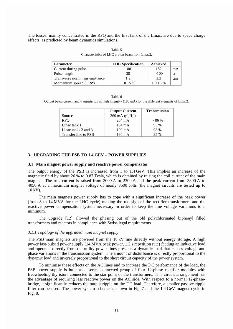
To minimise these effects on the AC lines and to increase the DC performance of the load, thePSB power supply is built as a series connected group of four 12-phase rectifier modules withfreewheeling thyristors connected to the star point of the transformers. This circuit arrangement hasthe advantage of requiring less reactive power on the AC side. With respect to a normal 12-phase-bridge, it significantly reduces the output ripple on the DC load. Therefore, a smaller passive ripplefilter can be used. The power system scheme is shown in Fig. 7 and the 1.4 GeV magnet cycle inFig. 8.
12
Fig. 7 Main magnet supply electrical diagram.

13
3.1.2 The reactive power compensation
The scheme described in Section 3.1.1 reduces the line harmonics on the 18 kV side and minimisesthe reactive power variations, but not sufficiently.
To obtain a satisfactory reactive power compensation and a sufficiently low total harmonicdistortion, an existing 18 MVAR capacitor bank and harmonics filter on the 18 kV level near the Jurasubstation at the Meyrin site is used [13]. The dynamic compensation is assured by a set of ThyristorControlled Reactors (TCR) installed next to the filter. All the filtering and compensating equipment isconnected to the power distribution system at the 18 kV level.
Particular care has been taken of the TCR control circuitry to ensure that variations of thenetwork voltage are kept to a minimum. The TCR was specified [14] and installed by the CERNpower distribution group and ordered within the Canadian collaboration with TRIUMF.
Fig. 8 Voltage (U) and current (I) of the 1.4 GeV cycle, and voltage excursion (∆U) on the 18 kV network. 100 ms/div.
During the 1.4 GeV cycle the variation of the line voltage on the 18 kV network is of the orderof 2.3 % without and 0.5 % with compensation. The latter figure contains other variations in thenetwork, as it is impossible to do measurements with an ideally stable network (see Fig. 8). Theinstallation has been in service for more than one year and, so far, no other users claim to beperturbed by the PSB magnet cycles.
3.1.3 The power converter groups
The original rectifier groups (four plus one spare) have been refurbished to deal with the increasedrms and peak power for the LHC cycle. However, the water cooling of the freewheeling thyristors hadto be upgraded and additional heat sinks for the fuses were installed to decrease their temperature.
The CERN power distribution group installed a complete, new 18 kV switch gear with theconnection to the primary of ten new rectifier transformers (two units in one tank, rated18kV/390V/2x 1.34 MVA). The latter were ordered as part of the Canadian collaboration withTRIUMF. The transformers were specified to be housed in the same position as the formertransformers in order to retain the same phase symmetrical connections to the rectifier bridges.
For the transformers a polygon primary to star secondary coupling was specified in order toconnect the freewheel thyristors to the neutral point and to have a higher turns ratio for the accuracyof the phase angle (±15° el. with a tolerance of 0.03°). Also much care was taken to ensure that theabsolute impedance (4 %) of all ten transformers had limited spread within phases and units (± 5 %).Both efforts were necessary to keep subharmonics (50, 100 Hz) as low as possible [15].
The over-voltage protection circuits on the secondary of the transformers were redesigned andadapted to the new layout.

14
The DC output connections of the rectifier modules (1000 V / 2300 A rms / 4050 A peak), theDC switching circuitry for the series connection of up to four groups, the passive filter and theconnections to the magnets have been taken over from the old system.
3.1.4 Regulation and control electronics
A magnet cycle editor running on the controls system allows the creation and storage of cycles fordifferent beam requirements. These cycles are sent to the main magnet supply via the local DeviceStub Controller (DSC).
Input to the current regulation electronics is the base current from the PS control interfaceMIL1553 bus and, via a serial digital function generator, the LdI/dt function. By measuring themagnet current by a DC Current Transformer (DCCT) and using a Digital Signal Processor (DSP) theIR component is added to the LdI/dt component to calculate the reference voltage for the magnet. Byintegration of the LdI/dt function a current reference is created and compared to the actual current.The difference corrects the reference voltage signal and eliminates the influence from the resistive(thermal) variations of the magnet [16]. A block diagram of the regulation is shown in Fig. 9.
Fig. 9 Block diagram of voltage and current regulation using digital reference processing.
The magnet voltage reference signal is distributed to the four rectifier groups and controlssuccessively the groups from zero to full voltage. Each rectifier group has its dedicated voltagefeedback loop. This enables the variation of the reactive power consumption to be reduced and tokeep the ripple of the voltage of the modules in series as low as possible.
The control of the 12 pulse rectifier-inverter bridges is done by high precision linearised gatecontrol sets with a resolution of 0.1° el.. There are two separate functions for each group: bridgemode and freewheel mode. During start up the firing pulses of the selected groups have to besynchronised and switched from freewheel to bridge mode. In case of a major fault the freewheelthyristors act as a crowbar and thus protect the main magnet.
On the current and field measurements disturbances with harmonics of the supply’scommutation frequency have been observed. The modification of the grounding of the magnet circuitand the installation of a common mode filter at the output of the power supply improved thesituation [18].
Most of the control and interlock functions as well as the digital part of the power supplyinterface to the controls system are performed by decentralised Programmable Logic Controllers(PLCs) interconnected by a serial fieldbus. Some vital functions (e.g. overcurrent) are hard wired inparallel to the PLC. The Mimic diagram and local and remote control are also integrated in the PLCsystem.
3.1.5 Quadrupole correction power supplies QFO and QDE
All bending and quadrupole magnets of the PSB machine are connected in series. To control thequadrupole magnets separately within a span of 8 % of the main current, two correction powersupplies are connected in parallel to the quadrupoles (see Fig. 7). These power converters are 12-

15
phase thyristor-controlled rectifiers with passive and active fast filters in series with a currentprecision and tracking error better than 10-3 of nominal current and high dynamic capability (4 kA/s).Nominal ratings are 300A/520V/150kW. The insulation to ground withstands 10 kV as the entiremain magnet circuit [17].
3.2 Main bending magnets “Trim” power supply
During the running-in period (in 1998) after the upgrade of the PSB to 1.4 GeV it became clear thatthe main bending magnets showed more effects of saturation than had been anticipated. The fieldvalues for the outer rings (rings 1 and 4) were slightly smaller as the magnet had been shimmed [19]to equalise field values at the former ejection energy of 800 MeV.
To equalise the bending fields the idea of the installation of a trim power supply wasdeveloped. Investigations of the cabling of the coils of the bending magnet string showed that thecoils for rings 1 and 4 as well for rings 2 and 3 are in series with connection points accessible fromthe power supply equipment room.
A switch-mode power supply was specified, ordered, constructed, installed and commissionedin a record time of 4 months [20, 21]. The main characteristics are:
• bipolar 1900 V
• current 0 – 50 A with 10 Arms
• total precision 0.2 % (ripple, tracking error, disturbance) relative to the maximum current ofthe main supply
• stable operation at zero current
• radiated and conducted switch noise below 50 mApp
• insulation to ground 10 kV, as the whole main magnet circuit.
To anticipate a step increase of the main current, the bending magnets voltage signal is used asa feed-forward voltage reference for the trim supply. This allows to reduce the tracking error of thetrim supply to nearly zero.
Control and interlocks of the trim supply are integrated as the QFO- and QDE- supplies(focusing and defocusing quadrupole magnet trim supplies) into the PLC system of the main powersupply and controlled by the same knobs as the main supply.
3.3 PSB-PS/ISOLDE beam-line power supplies
The PSB-PS beam transfer line was designed in the late sixties for 800 MeV protons. In mid 1980 thePSB was upgraded to 1 GeV without modifying the transfer line equipment. More recently it wasdecided to upgrade further to 1.4 GeV for future LHC operation while also making available 1 or1.4 GeV beams to the ISOLDE facility. Consequently, a number of magnets and power converters ofthe PSB transfer lines had to be replaced and this work was carried out in co-operation with TRIUMF,taking advantage of the Canadian in-kind contribution to the LHC project.
3.3.1 Requirements
The characteristics of the transfer line magnets and the related power supplies, as well as theoperational requirements at 1.4 GeV, are shown in Tables 7 and 8. Some of the magnets are DC whileothers require to be modulated in 600 ms between field values corresponding to 1 and 1.4 GeV oreven zero, 1 and 1.4 GeV. One magnet (BT.BHZ10), which directs the particles almost symmetricallyeither to the PS or to the ISOLDE / PSB measuring-line, has to perform a full current reversal at 1 or1.4 GeV within < 750 ms. To allow a certain flexibility during operation in the years to come, asuitable margin in voltage and current was provided when specifying the new power supplies.

16
3.3.2 Performance specification
The critical specifications for the new power supplies (Refs. [22, 23]) concern:
• the operational DC precision/stability of current referred to nominal set-point, to be better than1·10-4 over 8 hours;
• the capability of changing, on subsequent PSB cycles, the current by ± 25 %, or by 100 % insome cases, within 600/750 ms regulation transients included;
• the conformity to the PS control interface (MIL-1553) and to the operator interface in use inthe PS complex;
• the use of state of the art circuit topologies so as not to become obsolete once the LHC startsoperation.
With the view of simplifying the design of the power parts, the operational requirements of thetransfer line magnets were met by two sets of power supply ratings: a lower range up to 35 kW(Batch-1) and a higher one up to 250 kW (Batch-2).
Consequently the following types of power converters have been specified, (Tables 7 and 8):
• Batch-1 (38 units): type a1=15 kW (300 A, 50 V) with mechanical output current polarityselector; a2=31.5 kW (350 A, 90 V) and a3=35 kW (500 A, 70 V).
• Batch-2 (8 units): type b1=100 kW (500 A, 200 V) and b2=250 kW (450 A, 550 V).
Table 7Main operational parameters of power converters up to 35 kW and of related magnets (“B” means bending magnet,
“D” correction dipole, “Q” quadrupole. “PPM” stands for “Pulse to Pulse current Modulation” every 1.2 s).
3.3.3 Technical solution
Using today’s state of the art technology, Switch Mode Power Supplies (SMPS) have been specified,which have excellent precision/stability, low losses and fast regulation response [24].
Function Item Identification Magnet DC Resistance Operation at Imax (1.4GeV) Power Supply Remarks NotesType (w. cables) (Ω) Current (A) Voltage (V) Type Magnets: mH / mΩ / ms
PSB Injection Line 1 BI-BVT B5 (°) 0.175 250 (*) 44 a2 ppm1 B : 43 / 221 / 1942 BT1-BVT10 B 0.246 281 70 a2 ppm B1: 92 / 422 / 2183 BT4-BVT10 B 0.246 281 70 a2 ppm B4: 205 / 94 / 21804 BT-BVT20 B1 0.442 244 109.5 268 A -118 V ppm B5: 31 / 160 / 194 5 BT2-DVT10 D 0.09 147 13.5 a1 ppm (+/-) B6: 11 / 85 / 1306 BT3-DVT10 D 0.09 147 13.5 a1 ppm (+/-) B7: 15 / 110 / 1367 BT2-DVT20 D 0.09 248 22.5 a1 ppm (+/-) D : 3.2 / 80 / 40
PSB Transfer Line 8 BT3-DVT20 D 0.09 248 22.5 a1 ppm (+/-) Q : 48 / 160 / 3009 BT3-DVT40 D 0.09 124 11.5 a1 ppm (+/-) Q1: 160 / 260 / 615
10 BT2,3-QNO10 2 X Q 0.35 199 71.5 a2 ppm Q2: 240 / 200 / 120011 BT2,3-QNO20 2 X Q 0.35 189 68 a2 ppm (Bold = new TRIUMF magnet)12 BT-QNO30 Q 0.18 88 16.5 a1 ppm Power Converters: 13 BT-QNO40 Q 0.18 259 48 a2 ppm Type a1: 300 A - 50 V (18)14 BT-QNO50 Q1 0.27 197 60 a2 ppm Type a2: 350 A - 90 V (9)
15 BTP-QNO10 Q (°) 0.185 150 28 a1 dc (**) Type a3: 500 A - 70 V (2)16 BTP-QNO20 Q (°) 0.185 145 27 a1 dc (**) Batch1: 21xa1+ 11xa2 + 6xa3
PS Injection Line 17 BTP-QNO30 Q (°) 0.2 139 28 a1 dc (**) Operations:18 BTP-QNO40 Q (°) 0.2 177 35.5 a1 dc (**) ppm : 1 / 1.4 GeV19 BTP-QNO50 Q 0.2 152 30.5 a1 dc (**) ppm1: protons / ions20 BTP-QNO60 Q (°) 0.215 176 38 a1 dc (**) I1 : I1.4 = 0.79 : 1
ISOLDE Line 21 BTY-BVT116 B4 0.11 410 45 a3 dc I (ions ) = 1.12 x I (protons )22 BTY-QDE209 Q2 (°) 0.23 174 40 a1 dc ∆t available for ppm: 600 ms23 BTY-QFO210 Q2 (°) 0.23 221 51 a2 dc
GPS Line 24 BTY-DHZ212 D 0.1 243 24.5 a1 dc (+/-) (+/-) = mechanical - remote25 BTY-DVT212 D 0.1 243 24.5 a1 dc (+/-) controlled - polarity changer26 BTY-BHZ308 B4 0.13 410 53.5 a3 dc (*): Ions injection into the PSB27 BTY-QDE321 Q2 (°) 0.23 174 40 a1 dc (**): ∆I in ppm < 5%
HRS Line 28 BTY-QFO322 Q2 (°) 0.23 221 51 a2 dc (°) : Solid yoke29 BTY-DHZ324 D 0.1 243 24.5 a1 dc (+/-) (°°) : Secondary beam 30 BTY-DVT324 D 0.1 243 24.5 a1 dc (+/-) Location: BHP - ISOLDE Hall

17
Table 8Main operational parameters of power converters with 100 and 250 kW ratings and of related magnets
(“m1-4” means magnet. Other symbols as in Table 7).
As an illustration of the design, a block diagram of the power section of the 100 kW converteris shown in Fig. 10. Specifically, the power section of the converter consists of an AC series-parallelinput filter to reduce current harmonics and rise the power factor; a rectifier and filter forming the DClink; an Insulated Gate Bipolar Transistor (IGBT) full H-bridge operating at a switching frequency of16-18 kHz and a ferrite HF transformer with centre tap secondary, feeding a high current rectifierfollowed by two LC passive filter stages. To achieve a 600 ms current fall time despite of a load timeconstant of over 2 s in some case an optional regeneration thyristor bridge provides the requirednegative voltage on the magnet, and an IGBT switch isolates the converter from the load when thecurrent is requested to decrease to zero.
Fig. 10 Block diagram of a 100 kW switch-mode power converter.
The 250 kW converter has three IGBT H-bridges working in parallel and feeding theHF transformer whose secondary is connected to a Graetz-bridge rectifier followed by two LC filters.In addition to the regeneration section this converter has a thyristor selector of the DC current polaritywhich allows an invertion of the field which directs the protons either to the PS or to theISOLDE/measuring line. The semiconductor switches and some of the magnetics are water cooled toremove the losses and to obtain a compact assembly as required by this type of converters forelectromagnetic compatibility reasons.
All the voltage and current measurement systems used for monitoring, protection or feedbackare insulated. The power supply output current is measured via high precision magnetic sensors(DCCTs).
As shown in Fig. 11, the regulation of such a SMPS consists of several cascaded feedbackloops:
• a first loop balances the current in the two arms of each IGBT H-bridge to avoid saturation ofthe HF transformer by any DC component.
• A second loop controls and limits the current Ip on the primary of the HF transformer.
• A third fast loop controls the voltage Ur at the rectifier output.
Function Item Identification Magnet DC Resistance Operation at Imax (1.4 GeV) Power Remarks Magnets: mH / m: / ms
Type (with Cables) Current Voltage Supply m1: 92 / 480 / 192( Ω ) ( A ) ( V ) Type m2: 470 / 200 / 2350
m3: 370 / 400 / 925PSB Transfer Line 1 BT-BVT20 m1 0.5 244 123 b1 ppm m4: 205 / 94 / 2180
Power Converter types: 2 BT-BHZ10 m3 0.42 (+/-) 381 488 (398) b2 ppm Type b1: 500 A - 200 V (4)
Switchyards 3 BTY-BVT101 m4 0.11 397 158.5 b1 ppm2 Type b2: 450 A - 550 V (1)4 BTY-BHZ301 m4 0.13 397 163.5 b1 ppm3 Batch-2: 6xb1 + 2xb2
ppm2: 0 / 1 or 1.4 GeVMeasuring Line 5 BTM-BHZ10 m2 0.22 446 161 b1 ppm ppm3 = ppm2 for GPS / HRS
∆t available for ppm: 600 ms ( 0.75 s for BT-BHZ10)
(+/-): bipolar power supply b2

18
• Finally the overall feedback loop controls the magnet current and assures the stability andprecision.
The critical components of the current loop are enclosed in a Peltier oven block kept at constanttemperature by a separate feedback regulation.
Fig. 11 Block diagram of final power converter regulation.
As factory tests could not be performed on the actual load, the regulation had to be slightlymodified and adjusted during commissioning at CERN. This results in the best possible dynamic andstatic behaviour over the full current range.
To make the power supply electronics compatible with CERN standard control and operatorinterfaces, the principle of separating a 6U Euro-crate in two 3U sections was adopted. The upper onewas reserved for CERN specific boards and the lower one for the manufacturer’s electronic cards.This solution has been shown to work smoothly and to allow a clear definition of responsibilities witha minimum of interfacing conflicts.
3.3.4 Project wind up
Having equipment specified at CERN and built in Canada proved not to be an easy task. In additionto the distance and time lag, the different workmanship quality standards, work methods andmaterials in use, as well as the different culture of the North American market, have proved to bequite challenging. From the beginning the arrangement, that CERN would rather take care of thefollow up of technical aspects and of the compliance with the specification, and leave TRIUMF therole of managing the contracts and dealing with the suppliers, worked quite well. The powerconverters were designed, developed and manufactured by firms based in Toronto/Ca. Severalhundred CERN specific interface boards for all the power supplies were made, stuffed and pre-testedby a specialised firm located in Vancouver/Ca.
The Batch-1 power supplies have been in operation since March 1998 and have shownexcellent performance and availability records. Delivery of the Batch-2 power supplies is expected tobe completed early 2000.
3.4 Pulsed power converters for the septum magnets in the transfer line PSB-PS
The upgrading of the PSB-PS recombination and transfer line to 1.4 GeV called for new pulsedseptum magnets to replace the DC septa unsuitable for the increased currents (see Chapter 4.1). Forthe new septa, new pulsed power converters have been designed and installed in the transfer linePSB-PS. To meet the main features such as high current, high precision and duration of the flat-top,and to master thermal and magnetic problems owing to the irregular pulses (current and timingmodulation), a third harmonic correction of the discharge pulse was added and an active filterinserted [25].

19
A new electronic crate has been developed at CERN to facilitate the maintenance and to respectdifferent criteria: standardisation, protocol, timing and regulation with active filter. The power partshave been designed at CERN and built in collaboration with industry.
3.4.1 Operational requirements
In the common part of the transfer line between PSB and PS, the kinetic energy is either 1 GeV(ISOLDE) or 1.4 GeV (PS). The PS supercycle is made of basic cycles (1.2 s length) dependent onthe use of different beams. Consequently, pulsed power converters must work with an irregular pulserepetition and with pulse to pulse modulation of their current.
The recombination of the beam in the PSB transfer line uses: four superimposed horizontalsepta (BE.SMH with the four magnets in series), three vertical septa (BT1.SMV10, BT4.SMV10,BT.SMV20) and a horizontal septum for the injection in the PS (PI.SMH42).
3.4.2 Pulsed capacitors discharge power converters
The principle is based on the charge and discharge of capacitors through a resonant circuit betweencapacitors and the load. The charging current of the capacitors is controlled via thyristors on theprimary side of a high voltage transformer. The DC voltage and current are measured by voltagedividers and shunt. Once charged, the capacitors are discharged in the magnet via a power thyristor.In order to obtain a better flat top current than the basic sinusoidal discharge current, a third harmonicwith parallel LC circuit is added. A choke, in series with the discharge circuit, is used for the activefilter. The discharge is adapted with a matching transformer whose secondary delivers 4 to 12 timesthe primary current to the septum magnet.
3.4.3 Matching transformer and strip-line
The matching transformer is a special manufacture with air gap and a very low stray inductance. It isinstalled in the ring, and the secondary of the transformer is connected to a magnet vacuumfeedthrough via a high current strip-line made of copper plates to minimise the value of inductanceand to keep the resistance small relative to the magnet. The current in the septum is monitored by acurrent transformer between the pulse matching transformer and the high current strip-line.
3.4.4 Regulation and active filter
The capacitors voltage is regulated with a charging current internal loop. Temperature variations andmagnetic effects caused by irregular repetition rate are regulated by special electronics whichincreases or decreases slightly the capacitors voltage.
A current flat top stability of 10-4 is achieved by an active filter power circuit with a regulationcontrol loop. The principle is to charge the main capacitors slightly higher than the value necessary togive the current wanted. The excess current is then pulled through the inductance of the active filter,and the system acts in a closed loop through the matching transformer. More details may be found inRefs. [25, 27] and in the specification document [26].
3.4.5 Characteristics of the power supplies
The principal characteristics of the power converters are resumed in Table 9: Typical discharge andfilter currents are shown in Figs. 12 and 13, with a current of 33 kA in the PI.SMH42 septummagnet [27].
Installation of the pulsed power supplies for the septum magnets is now completed. Theyentirely fulfil the operational requirements: higher and repetitive currents for 1.4 GeV, pulse to pulsemodulation, irregular pulsing, high reliability so far.

20
Table 9Main parameters of the pulsed septum magnet power supplies.
BE.SMH BT1.SMV10 BT4.SMV10 BT.SMV20 PI.SMH42Peak current septum A 6000 30000 30000 30000 40000Transformer turn ratio n1/n2 4 12 12 12 12Charging voltage V 1200 2100 2100 2100 2100Peak current primary A 1500 2500 2500 2500 3333Total storage capacitors µF 2500 2000 2000 2000 3000Energy storage capacitors J 1800 4410 4410 4410 6 615Total inductance secondary µH 22 3 3 3 2.03Total resistor secondary µΩ 4020 660 660 660 620Current pulse half period ms 3.6 3.5 3.5 3.5 3.6Current pulse flat top µs 500 500 500 500 500Current flat top precision ppm < 100 < 100 < 100 < 100 < 100Pulse to pulse modulation yes yes yes yes yesIrregular pulse repetition yes yes yes yes yesMax. pulse repetition rate Hz 1 1 1 1 1Third harmonic choke µH 248 370 370 370 280Active filter choke µH 50 50 50 50 50Inductance seen by primary µH 432 503 503 503 372Power transformer 3 ph. kVA 20 63 63 63 63Prim./second. voltage effective V 400/1000 400/2000 400/2000 400/2000 400/2000
4. UPGRADING THE PSB TO 1.4 GEV – OTHER SYSTEMS
4.1 PSB-PS line septum magnets
In the PSB, DC septum magnets, that were originally designed for 800 MeV beams, have been usedfor 1 GeV beams, since 1986, without modification. When the PSB energy needed to be increased to1.4 GeV this implied redesigning all PSB ejection and transfer septa because of the thermal limit ofthe DC magnets. For the construction of these septum magnets, a single turn pulsed magnet approachhas been adopted, which requires less energy hence less cooling power. This way they are also lessprone to erosion in the cooling circuits. To attain the required vacuum, the laminated yoke of thesepulsed magnets must first be baked at 200°C, despite the fact that these magnets are installed in non-bakeable accelerators. Therefore, the connecting flanges of the magnet tanks should not exceed 50°Cwhen the magnets are being baked.
Fig. 13 Zoom on the flat top at 33 kA with active filtercurrent. The current flat-top precision is in the 10-4 range.
Upper trace: active filter current, 100 A/div,Lower trace: magnet current, 40A /div, 0.1 ms/div.
Fig. 12 Magnet and active filter current measured at 33 kAUpper trace: active filter current, 100 A/div,
Lower trace: magnet current, 10 kA/div, 0.5 ms/div.

21
To reach the objectives stated in theintroduction, the entire conception of themagnets has been revised. In the followingparagraphs, the most outstanding details willbe described per component.
4.1.1 Vacuum tanks
To reduce the risk of a leak developing duringa bake out, cylindrical tanks have been fittedwith circular ultra high vacuum flanges fordiameters < 200 mm and “Wheeler” flangeswith copper seals for the bigger diameters(>375 mm). The connecting flanges of thetanks to the accelerator vacuum chamber areof a conical “quick disconnect” type withaluminium seals, as standard in the CERN PSaccelerators.
4.1.2 Magnets
The new septum magnets, being of a pulsed type, are constructed with laminated yokes. Standard0.35 mm thickness steel laminations with a 3 % silicon content have been used, which are insulatedon both sides with a “Carlite” inorganic insulating coating. This solution provides a good inter-laminar resistance, and is still bakeable up to 200°C. The laminated yoke is held together in astainless steel support by ceramic coated endplates, while sitting on ceramic bars, to ensure theelectrical insulation between the yoke and the support.
The single-turn coils have been made of “OFHC” copper. The cooling circuit comprises twothin-walled stainless steel tubes, embedded (and brazed) in pre-machined slots in the septumconductor. This reduces erosion of the cooling circuit due to the high water speeds of up to 10 m/s. Toincrease the mechanical strength of the 60 mm gap septa conductors, a 0.5 mm thick stainless steelplate is brazed onto the outside of the septum conductor. To reduce the fringe field of the magnets,insulation has been eliminated between magnet yoke and septum conductor, while the returnconductor of the coil is insulated with several layers of 0.06 mm and 0.12 mm thermally pre-formed“Kapton” sheet (see Fig. 15).
Fig. 14 Vacuum tank containing 2 ejection magnets.
0.5 mm Stainless steel
Total thickness 5mm
Stainless steel cooling tubeinox D=2.5 x 2 mm
Braze
2 x copper wireD = 1.25 mm
Construction and Brazing detail septum conductor
5 mm
Septum Blade
Return Conductors
for fillingreinforcing plate
2 Cooling tubes
DETAIL
Fig. 15 Cross section of septum conductor.
Fig. 16 Cross section of magnet yoke assembly.
1. Damping Spring 2. Clamping Plate 3. CeramicSupport 4. Septum Conductor 5. Cooling Tube6. Rear Conductor 7. Lamination 8. Lever9. Stainless Steel Support.

22
The complete magnet coil is held inthe gap by clamping plates located outsideof the magnet yoke. These insulatedclamps retain the septum conductor in thegap, while a spring between the septumand rear conductor applies a mechanicalforce on the return conductor equal to theelectromechanical force at the peakcurrent.
The springs, spaced every 45 mm,are made of beryllium copper (5 % Be)suitably annealed to obtain the necessarymodulus of elasticity (see Fig. 16).
A water-cooled coaxial powerfeedthrough, developed for use at 10 kA
rms,
is used for all new pulsed septum magnets.The coaxial configuration provides thebest possible symmetry in mechanicalforces, (see Fig. 17)
4.1.3 Displacement system
All septum magnets can be moved remotely in the radial (or vertical, in the case of the septa in thetransfer line) and angular directions, while their vacuum tanks remain fixed. A variablepotentiometer, linked to the mechanical displacement system, provides a measurement of the positionof the magnet inside the tank. The resolutions of the radial and angular systems are 0.1 mm and0.1 mrad, respectively. For the initial installation, the magnet tank is aligned in all directions. In theevent of a failure, the entire vacuum tank with septum magnet can be replaced without the need forrealignment.
4.1.4 Beam screen
All septum magnet tanks (except transfer lines) are equipped with RF beam screens for the orbitingbeam. These screens insure the continuity of the RF impedance of the vacuum tanks, to avoidunwanted harmonics during acceleration. The beam screens are made of perforated stainless steelsheet to improve vacuum pumping speed, and are linked with the connecting flanges of the tank bymeans of RF contacts.
4.1.5 Vacuum equipment
The vacuum tanks are kept under vacuum with a dedicated set of ion pumps, additional pumpingbeing provided by titanium sublimators for the tanks installed in the accelerator rings. In view of thelarge surface of the magnet laminations under vacuum, and the pressure level to be obtained, it isnecessary to bake out the magnets before commissioning. Standard off-the-shelf infra red lamps areused inside the vacuum tank, with reflectors of electro-polished stainless steel. By connecting two inseries, the power consumption is reduced by a factor four, while their expected life time isdramatically increased. The temperature of the magnet is measured with ordinary Cu/Cn (Cn-Constantan) thermocouples, and the control and regulation utilises standard temperature regulators.
4.1.6 Calculations
For the first rough estimation of the septum magnet parameters, a program was used running underMicrosoft Excel developed in the CERN/PS/SEPTA section. To finalise the cross sectional design ofthe magnet a finite element based program called “FLUX2D” from Cedrat/Magsoft was used. Thelongitudinal design was determined using the finite element based program “OPERA3D/TOSCA”from Vector Fields, using a model developed in house to simplify the magnet model withoutsignificant loss of precision. For mechanical and thermal calculations the finite element program
Fig. 17 Cross section of power feedthrough.
1. Dilver / Stainless steel weld 2. Ceramic support3. External conductor 4. Main connection 5. Centralconductor 6. Main connection 7. Vacuum bellows

23
ANSYS from Swanson Analysis Systems was used, while the cooling requirements were checkedwith the CERN developed program TUBE, running under Microsoft Excel.
4.1.7 Measurement results and conclusions
Measurements of magnetic length of the septa confirm theoretical predictions to within 0.5 % of themodel. The fringe fields measured are less than 1/1000 of the gap field at a 50 mm distance from theseptum conductor, or better in case of the BE.SMH, (PSB Ejection) where a very low fringe field wasrequired. After a bake out cycle, consisting of a quasi linear temperature increase of 200°C over12 hours, a 24 hour period at 200°C, and an exponential temperature decrease of approximately48 hours, a vacuum of 6·10-10 to 4·10-9 mbar is achieved. Since the bake out lamps are installed withreflectors, the connecting flanges of the vacuum tanks never exceed 50°C, allowing the use ofaluminium seals for connecting to the accelerator vacuum chambers.
The new septum magnets constructed show that it is possible to achieve a vacuum in the low10-9 mbar range, even with laminated yokes under vacuum. In order to reach the low pressuresspecified, it is imperative to perform a pre-commissioning bakeout at 200°C. The bakeout isperformed using commercially available infra red lamps operated below nominal power to avoidexcessive temperatures on the vacuum chamber connecting flanges.
For completeness, the technical specifications of the septum magnets are listed in Table 10.
Table 10Technical specifications of the septum magnets.
BESMH BTSMV10 BTSMV20 PISMH42Leq. (m) 0.95 1.00 1.00 0.57B0 (T) 0.354 0.569 0.525 0.689∫B.dl (T.m) 0.336 0.566 0.523 0.390I (kA) single turn coil 7.0 27.3 25.2 33.1E (GeV) protons 1.4 1.4 1.4 1.4Deflection Angle (mrad) 47 79 73 55Gap height (mm) 25 60 60 60Gap width (mm) 89 116 116 116Septum Thickness (mm) 3.8 5 5 5Rear conductor thickness (mm) 7.6 8.8 8.8 8.81/2 sine pulse width (ms) 3.1 3.1 3.1 3.2Water flow (l/min.) 1.9 3.5 3.5 4.25Year of installation 1998 1999 1997 1996
4.2 PSB-PS transfer line magnets
Most of the magnets in the transfer line from the PSB to the PS had to be replaced, for two differentreasons. Some of the replaced magnets were not laminated, thus the induced eddy currents wouldhave hindered pulse to pulse modulation. For some other magnets, the cooling power was no longersufficient at the higher currents necessary for 1.4 GeV operation. The magnets are part of theCanadian in-kind contribution to the LHC project.
All the magnet yokes are laminated using low carbon steel sheets of 1.5 mm thickness stackedbetween non-laminated low carbon steel end plates. The coils are built from rectangular copperconductor with a circular cooling hole. The inter-turn and mass insulation is made from half-lappedglass fibre tape. The coils are vacuum impregnated using radiation resistant epoxy resin.
The BVT10 dipoles are window frame magnets with a single bedstead coil. A yoke extensionblock compensates the asymmetry caused by the coil head. The BVT20 magnet is similar to theBVT10, but with an aperture of twice the width and two symmetrical bedstead coils which areidentical to the BVT10 coils. The DVT correction dipoles are window frame magnets with a smaller

24
bending power. They have two bedstead coils. The yokes of the BT.QNO quadrupoles use a “figureof eight” design. The doublet version is built from two single yokes separated by appropriate spacers.Details about the magnet design and excerpts from the construction drawings can be found inRefs. [28, 29] and the references herein.
The quadrupoles were magnetically measured at TRIUMF with a newly built rotating coilsystem [30] and an existing Hall probe system. The dipoles were field mapped at TRIUMF using aHall probe system. Details of the measurements, comparisons between different measurementmethods and comparisons to magnetic field calculations can be found in Refs. [29-31] and thereferences herein.
Table 11 lists the magnet characteristics. The values given for cooling flow, temperature rise,and pressure drop are measured values. Higher currents are possible by increasing the inlet waterpressure, the maximum permissible value being 25 bar. Table 11 also contains the coefficients ∫Bdl/I,∫Gdl/I; the value for the BVT10 dipoles corresponds to the linear part up to 200 A. At the fieldnecessary for 1.4 GeV operation, a saturation of 0.7 % can be seen for this magnet, see Fig. 18. Thepolynomial coefficients to describe this curve can be found in [29]. For all other magnets saturationeffects are negligible at this field level. All values are averaged over a given magnet type, individualmeasurements for each magnet can be found in [29].
Table 11 Magnet characteristics: ∫Bdl and deflection angle correspond to the current given in this table.
BVT10 BVT20 DVT BTQNOsinglet
BTQNOdoublet
Deflection angle 78.5 70.0 max. 11.1 - - mradElements BT1.BVT10
BT4.BVT10BT.BVT20 BT2.DVT10
BT3.DVT10BT2.DVT20BT3.DVT20BT3.DVT40
BT.QNO30BT.QNO40
BT2.QNO10BT3.QNO10BT2.QNO20BT3.QNO20
Overall length 985 980 445 590 590 mmOverall height 460 460 280 500 1000 mmOverall width 340 530 440 700 700 mmYoke length 800 800 250 430 430 mmHorizontal aperture 62 120 102 - - mmVertical aperture 124 124 124 - - mmAperture diameter - - - 150 150 mmWeight 500 650 100 650 1400 kgCooling flow 7.7 13.5 3.5 5.3 9.7 l/minTemperature rise 35 28 20 30 30 oCPressure drop 4.2 3.5 3.5 4.5 4.3 barI (for given ∫Bdl / ∫Gdl) 275 234 250 260 260 AR at 20 oC 212.3 416.5 74.6 147.1 296.5 mΩR at 45 oC 235.3 460.8 82.4 162.9 328.2 mΩL at 100 Hz 39.8 86.5 2.68 39.0 78.4 mHL at 1000 Hz 32.6 72.7 2.16 34.3 69.2 mHDissipated power 17.8 25.3 5.2 11.0 22.0 kWB 0.6189 0.5476 0.1971 - - T∫Bdl 0.5611 0.5003 0.07957 - - TmG - - - 6.612 6.614 T/m∫Gdl - - - 3.082 3.082 Tm/m∫Bdl/I (BVT10: I<200A) 2.0555 ⋅10-3 2.1370 ⋅10-3 3.1830 ⋅10-4 - - Tm/A∫Gdl/I - - - 1.1854 ⋅10-2 1.1854 ⋅10-2 T/AEffective length 906.6 913.6 403.8 466.1 466.0 mm
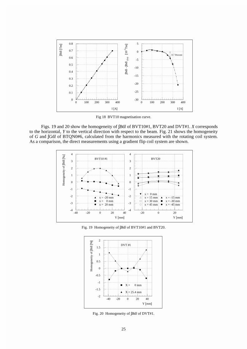
25
Fig 18 BVT10 magnetisation curve.
Figs. 19 and 20 show the homogeneity of ∫Bdl of BVT10#1, BVT20 and DVT#1. X correspondsto the horizontal, Y to the vertical direction with respect to the beam. Fig. 21 shows the homogeneityof G and ∫Gdl of BTQN0#6, calculated from the harmonics measured with the rotating coil system.As a comparison, the direct measurements using a gradient flip coil system are shown.
Fig. 19 Homogeneity of ∫Bdl of BVT10#1 and BVT20.
Fig. 20 Homogeneity of ∫Bdl of DVT#1.
Y [mm]
Hom
ogen
eity
of
∫Bdl
[%]
DVT #1
X = 25.4 mm
X = 0 mm
-2
-1.5
-1
-0.5
0
0.5
1
1.5
2
-40 -20 0 20 40
I [A]
∫Bdl
[Tm
]
I [A]
∫Bdl
- ∫B
dl (l
in)
[10-3
Tm
]
0.7 Percent
0
0.1
0.2
0.3
0.4
0.5
0.6
0.7
0.8
0 100 200 300 400-30
-25
-20
-15
-10
-5
0
5
0 100 200 300 400
Y [mm]
Hom
ogen
eity
of
∫Bdl
[‰]
BVT10 #1
x = -20 mmx = 0 mmx = 20 mm
Y [mm]
BVT20
x = 0 mmx = 15 mmx = 30 mmx = 45 mm
x = -15 mmx = -30 mmx = -45 mm
-4
-3
-2
-1
0
1
2
3
4
-40 -20 0 20 40-4
-3
-2
-1
0
1
2
3
4
-20 0 20

26
Fig. 21 Homogeneity of G and ∫Gdl of BTQNO#6.
4.3 Fast kicker systems
4.3.1 PSB ejection BE.KFA14L1 and recombination kickers BT.KFA10 and BT.KFA20
The PSB kicker magnets are used for the horizontal ejection and sequential vertical recombination ofthe beams from the four PSB rings into one string of bunches, which is being guided to the PS. Themagnets are of cellular, closed aperture, C-ferrite loaded, transmission line type; they are inserted inthe machine vacuum. Ejection and recombination magnets have different apertures to best match thebeam dimensions. Given the constraints of the PSB ring and transfer line layout, the original magnetsand vacuum tanks were re-used. The particularity of the original PSB kicker system configuration[32] was the insertion of the magnets between the Pulse Forming Network (PFN) and transmissioncables, as sketched in Fig. 22, below.
The principal advantage of this extremely tailored layout is that the magnets are used in virtualshort-circuit mode. The short-circuit current is provided immediately by the thyratron switch and itsleading edge travels only once through the magnet. This configuration yields the fastest kick rise-timeand highest kick strength for a given PFN voltage. Although the PFNs are resonantly charged inmilliseconds, the crucial disadvantage of this configuration, however, is the relatively long exposureof the magnet to the PFN charging voltage, which may precipitate magnet sparking for chargingvoltages larger than ~ 35 kV. Because of the increase of PSB energy, (the charging voltage for thekicker pulse generators is 26 % higher), this original air-insulated generator configuration could notbe retained, except for the second recombination kicker BT.KFA20, which operates far below themagnet voltage hold-off. This minimal cost system has other disadvantages:
• The impedance at the main thyratron switch is low (6.25 Ω), thus increasing the relativeimportance of unavoidable inductive mismatches present in such systems.
• Timing and transmission cable length adjustments, possible with independently poweredmodules, which are very effective to reduce the influence of individual magnet kick rise-timeand ripple on the sum kick of the magnets, cannot be made.
At previous occasions of PSB energy upgrades and consolidations, the initially effective, butcumbersome ferrite loaded pulse-steepening lines [33] (Fig. 22) were removed. High voltagethyratrons, vacuum feedthroughs and the magnet ferrites were upgraded (except for BT.KFA10), andall PFN and transmission cables were replaced by low loss, SF
6 pressurized high voltage cables.
X [mm]
Hom
ogen
eity
of
G [%
]
Gradient coil
From Harmonics
(Short rotating coil)
X [mm]
Hom
ogen
eity
of
∫Gdl
[%]
Gradient coil
From Harmonics
(Long rotating coil)-8
-6
-4
-2
0
2
-50 0 50
-8
-6
-4
-2
0
2
-50 0 50

27
For the present LHC upgrade the PSB kicker equipment (hardware and software), wascompletely replaced, except for the magnets, vacuum tanks and high voltage cables, previously dealtwith.
New, oil-insulated pulse generators using two multistage thyratrons, each capable of operatingat 60 kV and in two-shot Pulse to Pulse Modulation (PPM), were developed and installed togetherwith their associated electronics and controls for BE.KFA14L1 and BT.KFA10, systems which arevery similar. These magnets are now hard short-circuited and pulsed in the more classicalconfigurations of Figs. 23 and 24. For BT.KFA20, the new hardware developed for the above systemsis also used, but the original configuration has been retained in order to achieve the short rise-timewithout the need of bulky artifices, Fig. 25.
The principal advantage of the new layout is that the short-circuited magnets (and theirelectrical feed-throughs) are exposed to high voltage for the minimum possible duration, largelyobviating the problem of sparking. The intrinsic disadvantage of this new configuration with respectto the previous layout is that the initial switch current has to traverse the magnet twice before the totalkick is established, leading to a longer rise-time (~90 ns instead of ~60 ns). However, because of thePSB harmonic number change from 5 to 2 or 1, this longer rise-time can be accepted.
Development work is actually in progress to improve the rise-time, including the eventual useof small saturable ferrite loaded inductors, and to reduce flattop ripple by adequate compensation ofthe various unavoidable mismatches. Other complications inherent in this configuration are differentlengths of transmission cables to compensate for particle flight time from magnet to magnet.
The main parameters of the PSB kickers can be found in the Table 12 and more information ison the web via http://nicewww.cern.ch/psdata/www/Kickers/psparam.htm.
Fig. 22 Original BT.KFA20 configuration. Fig. 23 BE.KFA 14L1 (1 of 4 rings) for LHC era.
Fig. 24 BT.KFA 10 configuration for LHC era (1 of 2 lines). Fig. 25 BT.KFA 20 configuration for LHC era.

28
Table 12PSB and PS Kicker main parameters and performances (kick strengths for Imax)
Element No.ofGene-rators
VPFN(kV)
MagnetZo (Ω )
nominal
Termi-nationZ (Ω )
MagnetImax
(kA)
No.of
turns
MagnetAperture
w×h (mm)
Magnetlength(mm)
Kickstrengthin SS/ring
(G.m)
ise-time2-98 %
Flattoplength(µs)
BE.KFA14L1 4 60 25 s/c 2.4 1 115x70 450 775 102 ns 1.5BT.KFA10 2 60 12.5 s/c 4.8 1 53x110 786 862 86 ns 1.5BT.KFA20 1 30 12.5 s/c 2.4 1 53x110 786 431 80 ns 2.7PI.KFA45 4 80 26.3 26.3/ 0 .5 / 3 1 150x53 222 314.2 / 601.5 49 ns 0 - 2.6PR.KFA71-79 12 80 15 15 2.6 1 147x53 221 1673 85 ns 0 - 2.1BE.BSW14L4 1 0.5 - - 0.765 36 141x144 540 946 5.25 ms 100BE.BSW15L1 1 0.5 - - 0.845 24 144x72 378 1336 5.25 ms 100BE.BSW15L4 1 0.5 - - 0.765 36 141x144 540 946 5.25 ms 100
4.3.2 PSB ejection dipoles
For ejection at 1.4 GeV it was necessary to increase the bumper magnet peak current from 500 A to630 A. Whilst it was possible to conserve the existing magnets, their associated pulse generators werelimited to 550 A peak current. In addition, the bumpers are now required to operate in PPM between1 GeV and 1.4 GeV. In view of these new operating conditions, the necessity to interface to a newDSC-based control system and their advanced age, it was decided to completely replace the existingpulse generators [34].
The existing magnets, in use since 1970, are retained. BE.BSW14L4 and BE.BSW15L4 arePSB type 5 magnets, BE.BSW15L1 is a type 6 magnet. The magnets are connected in a series/parallelconfiguration which presents an effective impedance equivalent to that of a single magnet. Thisarrangement is identical for the three straight sections. Each bumper pulse generator excites fourvertically superimposed magnets. The relevant parameters for the three sections are given inTable 12. For operational purposes, Imax
is hardware limited to 690 A for all twelve magnets.
The operating principle is based on a resonant semi-sinusoidal current discharge into thebumper magnet with a freewheel diode/inductor circuit providing a partial recharge of the primarycapacitor C1. Figure 26 shows a simplified electrical circuit for one bumper magnet group and itsassociated power supply.
Fig. 26 Simplified circuit diagram of one bumper magnet group (four superimposed magnets).
C1 is charged to a voltage V by a current source I1. When the semiconductor switch, SCR1, istriggered on, a resonance is excited between C1 and the magnet inductances L_ring1, L_ring2,L_ring3 and L_ring4. This slightly-damped sinusoidal current is interrupted by the opening of SCR1at the instance of zero-crossing. Time to peak of the current pulse is 5.25 ms. The free-wheel circuit

29
comprising D1 and L_recovery begins to conduct when the voltage on C1 goes negative; a secondary,lower-frequency resonance then occurs between L_recovery and C1 which ends when the current inD1 starts to become negative. This results in C1 completing the cycle with a positive charge therebyreducing both the power losses and the post-cycle recharge period. An additional series inductance isrequired in the 15L1 circuit to compensate for the lower inductance of the type 6 magnet compared tothe type 5 magnets.
4.3.3 PS injection and ejection kickers
The present PS injection and ejection kickers will be re-used in their actual configuration becausethey are sufficiently powerful. The PS injection Kicker PI.KFA45 works in a particular configuration(Fig. 27), which permits the doubling, in PPM, of the kick duration by short-circuiting the magnetsand using timing shifts for use with ions. However, as proton injection for LHC is performed in two-batch filling mode, the present kick rise-time must be shortened to ~95 ns. This improvement will bedone with saturable inductors and matching elements, which will also be effective for the flatness andfall-time of the kick.
The improvement required for the PS ejection kicker KFA 71-79 (Fig. 28) is more dramatic. Inthe nominal scheme, 3 out of 84 bunches have to be discarded, leading to the specified rise-time of95 ns. However, even if 4 bunches are discarded, the resulting kick rise-time of 120 ns (0.5 - 99.5 %)and flat-top stability of ± 0.5 % are very difficult to achieve. So far extensive computer modellingindicates that this requested performance could be obtained. At present, preparations are underway toexperimentally verify the predictions on full-scale laboratory equipment.
4.4 More Powerful Water and Air Cooling Systems for the PSB
The elements of the PSB (mainly magnets and power supplies) are cooled with demineralized water,distributed in three separated circuits: “Anneau”, “Zones”, and “Locaux Techniques”. While eachcircuit has a different inlet cooling water pressure, the temperatures are equal. Moreover, they have acommon return circuit.
Operating the PSB at 1.4 GeV raises the power dissipation of the main magnets (dipoles andquadrupoles) by about 60 % which the present cooling system can not tackle.
The demineralised water is circulating in a closed loop and cooled in heat exchangers whoseprimary coolant is industrial town water, sent to the drain after use. To avoid this waist of preciousresources at considerable cost, CERN has decided on a policy to gradually replace town water byclosed-circuit water systems using atmospheric coolants (cooling towers). For these reasons, acomplete renovation of the PSB water cooling and air conditioning systems was launched (seeTable 13 for the system’s key parameters).
The upgrading of the water cooling system implied (Fig. 29):
• Concentration of all system components in a new building (Nr. 237).
• Construction of a closed-circuit cooling plant based on cooling towers, thus avoiding the wasteof about 100 m3/h town water.
Fig. 27 PS injection kicker KFA45 (1 of 4 modules). Fig. 28 PS ejection kicker KFA71-79 (1 of 12 modules).

30
• Increase of the installed cooling power from 4 to 5.2 MW.
• Matching of the cooling requirements to just one single demineralised water supply withcommon temperature and pressure.
• Installation of a new device to generate demineralised water in adjacent building 141, with acapacity of 6 m3/h, aiming at a water conductivity below 2 µS. It is based on reverse osmosisand does not any more require periodic in-situ regeneration of chemical products, except forthe final ion exchangers.
Table 13PSB water cooling system, old and new: key parameters.
Old system New systemInstalled cooling power [MW] 4 5.2Demineralised water circuit Anneau Locaux
Techn.Zones Anneau +
Loc.techn.and TT2
Zones
Flow rate [m3/h] 90 57 22 270 35Max. inlet temperature [0C] 20 20 20 27 27Inlet pressure on magnets [bar] 10.5 10 18 13 14.7Outlet pressure on magnets [bar] 5 5 6 4.4 3.7Press. difference available [bar] 5.51 5 12 8.61 11Primary water circuit Town water to drain Water recycled via
cooling towersTotal flow rate [m3/h] 1202 465Average temperature [0C] 13 24Water pressure [bar] 6 2.5Replacement town water [m3/h] - 202
Note that the primary water temperature of the new system will be subject to seasonal changesof the atmospheric coolant (air temperature, humidity), with concomitant variations of the PSBmagnet temperature of up to 7°C. An extensive Machine Development (MD) session in July 1996 hasdemonstrated that this temperature increase does not impair at all the PSB machine performance [35].
The present air conditioning system, with an installed power of 1.8 MW, is also being adaptedto atmospheric coolants, thus saving further 90 m3/h of industrial town water (Table 14). The newdevice will also be accommodated in building 237.
Table 14PSB air cooling system, before and after upgrading.
Old system New systemInstalled cooling power [MW] 1.8 3Primary water circuitFlow rate [m3/h] 100 258Average temperature [0C] 13 24Town water consumption [m3/h] 100 (to drain) 10 (replacement)Saving in town water consumption [m3/h] 90
1 The higher pressure difference on the magnets copes with the increased dissipation power at 1.4 GeV.2 Thus the saving in town water consumption is 100 m3/h.

31
More detailed information on this upgrading programme may be found in [36]. The overallsaving in town water consumption (both systems) amounts to 190 m3/h, with a concomitant costsaving (1999 prices) of some 170 kCHF/year. The renovated systems become operational for theaccelerator start-up in March 2000.
Fig. 29 Demineralised water cooling system of the PSB after upgrading.
5. NEW RF HARMONICS TO ENABLE PS TWO-BATCH FILLING
5.1 New PSB RF cavities h=1 (0.6 – 1.8 MHz)
The addition of cavities accelerating on RF harmonic h=1 and supplemented with a h=2 system,contributes to reduce harmful space charge effects and avoids the coupled bunch instabilitiesobserved with the former acceleration scheme on h=5 [2]. These advantages are exploited equallywell for all other proton beams handled in the PS accelerator chain [37]. System properties aresummarised in Table 15.
A nominal peak RF voltage of 8 kV with ample margin is required, since high-intensity beamsbeyond 1013 particles per pulse and per PSB ring are to be handled. Vertical installation space isscarce due to the particular PSB construction with four superimposed rings restricting the vertical sizeof any equipment. For this reason the idea to squeeze four cavities in one PSB straight section wasabandoned, and a second section had to be sacrificed to allow usage of large size ferrite rings.

32
Table 15Main parameters of C02 RF system.
Frequency Range MHz 0.6 - 1.8 Permeability at remanence ~600Cav. Equiv. Capacitance3 pF 700 Tuning Bias A*turn 0-500Quality Factor3 @ Power density mW/cm3 64
0.6MHz 6.5 Magn. RF Flux Density mT 4-121.2MHz 16 Cooling Air Flow m3/s 11.8MHz 28 Ferrite Ring Size cm 48x24x3
Cav. Shunt Res.3 @ kΩ Total Ferrite Length cm 15000.6MHz 2.5 Nominal Gap Voltage kVp 8.01.2MHz 3.0 Max. Gap Voltage kVp 10.01.8MHz 3.4 Power Loss kW 13.0
Beam Impedance at Ω ~300 Peak Power kW 50resonance (with FB) CW Power kW 20Ferrite Type (Philips) 4A11 RF Feedback Loop Gain dB 20
5.1.1 Cavity design
A classical and conservative NiZn ferrite-baseddesign was chosen, replicating essentially the one-gap design with virtual ground symmetry in thegap mid plane of the other two PSB RF systemcavities (Fig. 30) [38]. Air cooling of the ferritethrough 1 mm spacing between rings gives thebest ferrite filling factor, keeps the mechanicalconstruction simple and is very cost effectivecompared with water cooling. The choice ofPhilips ferrite material grade 4A11 was made aftertests on several small size ring samples, with theabsence of resonant absorption phenomena in therequired working area as main criterion.
PSB operation implies synchronisation of the four rings with the PS cycle on a magnetic flattop (duration up to 60 ms) at constant or very slowly changing RF frequency around 1.8 MHz. It isknown that under such conditions ferrite can jumpinto the so-called High Loss Mode (HLM) atcritical excitation and disturb the servo control ofthe RF voltage amplitude [39]. The onset of HLMappears to arrive earlier at higher DC saturation ofthe ferrite, i.e. towards the high frequency end ofthe tuned cavities. Figure 31 shows the measuredeffect. The ferrite volume and cross section waschosen to stay safely below HLM onset at nominalRF voltage (8 kVp). The selected ferrite gradeexhibits a smooth and fairly stable transition intoHLM and experience has shown that safeoperation well beyond nominal voltage is possible.A temperature check of the individual rings in theoperational cavities replaced laborious ferritereception testing.
3 As seen across the gap at nominal voltage, with final amplifier and all accessories connected.
Fig. 30 Ferrite loaded cavity C02.
0
0.5
1
1.5
2
2.5
3
3.5
4
4.5
5
0 50 100 150 200
ms
A 9kV10kV11kV
Fig. 31 Final cathode current vs. time and gap voltage
at f = 1.8 MHz.

33
5.1.2 RF amplifier chain
A conservatively-rated power amplifier was developed using the tetrode RS1084CJ, already widelyused in the PS 10 MHz RF systems. Two newly developed wide-band transistor amplifiers plus a
power combiner (100 kHz...100 MHz) serve bothas driver and fast feedback amplifier. The wholeunit is water-cooled. Feedback of the gap RFsignal provides reduction of the cavityimpedance to the beam by about 20 dB. Highervalues are possible when needed. A particularityof the design is the use of a tuned low Q resonantgrid circuit [40] synchronised with the DC tuningcurrent of the cavities. Advantages are highergain, smaller drive power and the possibility toprogram phase response for increased feedbackloop stability. The movable amplifiers are placednear to the cavities and can be easily replaced incase of a repair. The system layout is sketched inFig. 32.
5.1.3 System electronics layout
The system electronics were developed to cover the frequency range of 0.5-20 MHz and are used inall PSB RF systems. Servo control of RF voltage amplitude is provided by logarithmic detector andmodulator electronics (Fig. 32). The detector has a 70 dB dynamic range and ~0.5 dB absoluteprecision in the working range. Frequency response to modulation is 200 kHz for the detector and
40 kHz for the voltage control loop. Thecavity tuning uses a novel IGBT linearcurrent amplifier, which is controlled by areactive power detection module. Maximumcurrent is 400 A and tuning loop response tosmall perturbations extends to 500 Hz. Thefrequency to tuning current relationship ispre-programmed in a memory; fine tuning ishandled in the analogue feedback loop whichautomatically turns on when the gap voltageexceeds ~100 V. An RF overpower detectoracts rapidly on the final tube screen grid toprevent system trips. Two such systems asshown in Fig. 33 are installed in PSB straightsections 10L1 and 7L1.
5.2 Converted PSB h=2 cavities (1.2 – 3.9 MHz)
With the abandoning of RF harmonics h=5 it became possible to modify the existing equipment forh=2 operation at little cost. Cavities modifications mainly consisted in increasing the gap equivalentcapacitance, so as to shift the working frequency to 1.2 - 3.9 MHz, and replacing the gap voltagedivider with a calibrated, wide-band unit.
Although the gap voltage required for h=2 operation is only 2/3 of the previously used voltageat h=5 (8 kV instead of 12 kV), the frequency decrease by a factor 2/5 results in an RF inductionincrease given by the ratio of the two factors (~ 1.7). This pushes the ferrite (Philips 4L2) more to itslimits, and the nominal RF voltage is reached without much margin. Ferrite entering into HLM,which with this ferrite grade appears to be unstable, is the critical parameter. Operation at constantfrequency (~3.5 MHz) for synchronisation of the four rings with the PS RF system, has to be limitedin duration as shown in Fig. 34.
Fig. 32 C02 system layout.
Fig. 33 C02 test mount for PSB rings II and IV.

34
The existing push-pull power amplifiers, using two RS2012CL tetrodes, have been retainedwithout modifications. They are air-cooled and share the cooling system with the cavities (Fig. 35).
Standard 100 W wide band amplifiers already used in the C02 systems have been added as fastfeedback power drivers. Feedback of the gap RF signal provides reduction of the cavity impedance tothe beam by 20-26 dB.
Although most of the heavy hardware has been retained, control and servo electronics havebeen replaced with the new, wide-band standard electronics developed for the C02 system. Thesystem properties are therefore similar to those already described in the previous section. Systemproperties are summarised in Table 16.
Table 16Main parameters of C04 RF system.
Frequency Range MHz 1.2 – 3.9 Tuning Bias A*turn 0 - 1800Cav. Equiv. Capacitance4 pF 650 Power density mW/cm3 31
Magn. RF Flux Dens mT 3.2 – 9.4Cooling Air Flow m3/s 1Ferrite Ring Size cm 35x20x3
Quality Factor4 @ 1.2MHz
2.5MHz3.9MHz
85130190 Total Ferrite Length cm 1500
Nominal Gap Voltage kVp 8.0Max. Gap Voltage kVp 9.0Power Loss kW 3.0
Cav. Shunt Res.4 @1.2MHz2.5MHz3.9MHz
kΩ17.512.512.0 Peak Power kW 20.0
Beam Impedance (with FB): kΩ CW Power kW 10.01.2MHz 0.882.5MHz 0.79 Feedback Loop Gain @ dB3.9MHz 1.07 1.2MHz 26
Ferrite Type ( Philips ) 4L2 2.5MHz 24Permeability at Remanence ~200 3.9MHz 21
4 As seen across the gap at nominal voltage, with final amplifier and all accessories connected.
10
100
1000
1 1.5 2 2.5 3 3.5 4 4.5
MHz
ms
6kV 7kV
8kV
9kV
Fig. 34 High loss mode on-set time. Fig. 35 C04 system layout.

35
5.3 PSB beam control modifications
The PSB is composed of four superimposed rings, each having three cavities described in Table 17.
The present beam control was installed in 1998 within the framework of the harmonic changefrom h=5 to h=1 and/or h=2. Its structure is based on one digital frequency synthesiser per cavity,each digital frequency word being directly derived from the main magnetic field measurement (B to fconversion). The present architecture is represented in Fig. 36. For one PSB ring, the parameters ofthe LHC beam are: one single proton bunch, 190 ns long, obtained with longitudinal blow-up(momentum spread ∆p/p = 2.5·10-3 ( 2σ).
Table 17PSB cavities.
Cavity Frequencyrange
Maximumvoltage
Use (for protons) Use (for ions)
C02 0.6 → 2 MHz 8 kV Acceleration on h=1 Acceleration h=4 up to 1.8MHz (frev=450 kHz)
C04 1.2 → 3.9 MHz 8 kV Bunch flatteningBunch splitting (h=1→2)at 1.4 GeVAcceleration on h=2
Acceleration on h=4 from1.8 MHz (frev =450 kHz) up to3.86 MHz (frev =965 kHz)
C16 5 → 16 MHz 6 kV Controlled longitudinalblow-up (h=9) near 1.4GeV
5.3.1 Hardware layout.
Figure 36 shows that the measured value of the dipolar field (“B-train”) is used for generating thefrequency words feeding all three cavities. The revolution frequency (frev
) is obtained from a look-uptable (typically a read only memory) and multiplied by the harmonic number aimed for C02 (h=1 forLHC beams). The resulting frequency is summed with the loop (phase and synchronisation) errorsignals, so as to obtain the actual C02 RF value sent to the cavities via a digital synthesiser.
The same principle applies for C04 and C16 cavities. Moreover, depending on the user, C04 isoperated in single or dual harmonic mode. In the former case C04 is working on its own at h=2 (forsome proton beams), whereas in the latter case it is tracking the C02 (h=1) cavity so as to obtainparticular bunch shapes to improve for example the bunching factor.
DipolarField[Tesla]
Look-upTableB to Frev
DDS
C02Drive
LoopControl
C02 Gap
Beam
C04 Gap
EjectionReference
∆Φ
∆ΦC02 Gap
DDS
C04Drive
LoopControl
∆Φ
C04Gap
C02 Gap
Beamh =1 or 2
h C02 hC04/hC02 DDS
C16Drive
FunctionGenerator
hC16/hC04
Fig. 36 PS Booster Beam Control layout.

36
C16 is used as a “controlled blow-up” cavity and therefore not included in any loop. Itsfrequency word is modulated by a function generator. The blow-up principle is similar to the one usedin the PS or SPS [41] and consists of a phase modulation (typically at 3 fS
) of a high harmonic signal(h=9).
The main advantages of the digital structure are:
• The look-up-table on the left-hand side of Fig. 36 sets the RF frequency so as to keep the beamon orbit for any magnetic field. This feature makes it possible to accelerate a beam with allloops open (albeit with some losses and instabilities). In the previous (analogue) version, onlythe radial loop could establish the required frequency to keep the beam centred but theposition detectors were quite hard to run at low intensity beams (e.g. lead ions).
• All cavities are naturally locked in frequency even with loops open; this avoids the presence ofan integrating type of corrector in the different phase loops (simplified correctors and morestability margins).
• In the old system, the loss of beam led to saturation of the different loops and erraticbehaviour of the frequency and voltage programmes necessitating security interlocks, quiteheavy to handle, to protect the power equipment. In the new system the loops just need to acton a small frequency range and do not provoke cavity trips.
5.3.2 The transition to h=1
Since its running-in period in 1972, the PSB machine was subject to many improvements. The mostperceptible in 1983 consisted in the introduction of a second harmonic cavity on each ring. The peakaccelerated intensity levelled off from that time at about 3.4·1013 protons per pulse (ppp) with all fourrings (1.1·1013 on ring 2). The introduction of a fast feedback on the cavities in 1985 consolidated theoperation, but did not improve the record value.
During the first h=1 run in 1998, the operation was disturbed by the impedance of the vacuumflanges around the ring. The resonances of these flanges gave a total (integrated around the ring)longitudinal coupling impedance of 450 Ω at 750 kHz [42] which is the RF frequency range at thebeginning of the cycle. The return voltage generated by the beam current was coupling to differentelectronic devices which therefore had to be equipped with common mode rejection circuits. Somecoupling between rings remained, implying adjustment of the radial position to avoid beating betweencavities near the synchrotron frequency. After some flanges had been short-circuited [42] during the1998-99 shutdown the total impedance was lowered to about 200 Ω (still higher than the maximumvalue for h=5 which was 130 Ω). This eliminated the frequency beating from one ring to the other asa source of trouble and helped to reach a new intensity record in September 99: 4.1·1013 pppaccelerated in the PSB with 1.2·1013 in ring 2. New RF decoupling flanges will be introduced in the1999-2000 machine shut-down to further reduce the impedance.
The transition to h=1 eliminated the coupled bunch mode instabilities (inexistant with a singlebunch) and thus made the complex feedback system as well as the “Hereward” damping system(tackling quadrupolar bunch-shape oscillations) superfluous. This last effect, not formally studied,might be explained by a criterion given in Refs. [43, 44] that relates the loss of Landau damping tothe beam current. The current threshold, proportional to VRF
/h, has been improved by a factor 3.3when moving from h=5 to h=1. The absence of the quadrupolar loop indirectly permitted an increaseof the h=2 versus h=1 voltage ratio limited to 50 % in the former system where beam amplitudedetection was misled by double peaked bunches.
Another improvement came from the C04 (h=2) cavities. These were obtained from theconversion of the older C08 cavities that were used as the main h=5 drive cavities. They have morevoltage and power margin than the previous C16 cavities used at h=10 and thus run more reliablywhenever the phase relationship between h=1 (C02) and h=2 (C04) is critical in terms of powerdemand from h=2.
All these improvements certainly contributed to the record intensity increase.
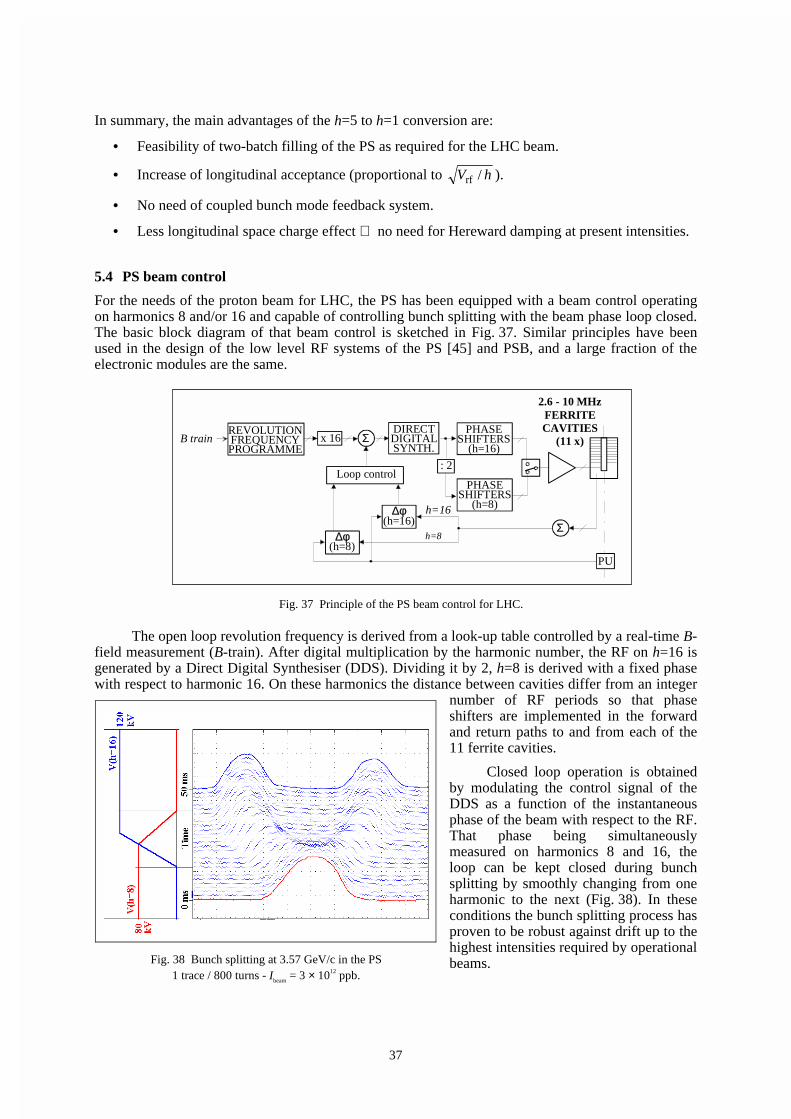
37
In summary, the main advantages of the h=5 to h=1 conversion are:
• Feasibility of two-batch filling of the PS as required for the LHC beam.
• Increase of longitudinal acceptance (proportional to hV /rf ).
• No need of coupled bunch mode feedback system.
• Less longitudinal space charge effect ⇒ no need for Hereward damping at present intensities.
5.4 PS beam control
For the needs of the proton beam for LHC, the PS has been equipped with a beam control operatingon harmonics 8 and/or 16 and capable of controlling bunch splitting with the beam phase loop closed.The basic block diagram of that beam control is sketched in Fig. 37. Similar principles have beenused in the design of the low level RF systems of the PS [45] and PSB, and a large fraction of theelectronic modules are the same.
The open loop revolution frequency is derived from a look-up table controlled by a real-time B-field measurement (B-train). After digital multiplication by the harmonic number, the RF on h=16 isgenerated by a Direct Digital Synthesiser (DDS). Dividing it by 2, h=8 is derived with a fixed phasewith respect to harmonic 16. On these harmonics the distance between cavities differ from an integer
number of RF periods so that phaseshifters are implemented in the forwardand return paths to and from each of the11 ferrite cavities.
Closed loop operation is obtainedby modulating the control signal of theDDS as a function of the instantaneousphase of the beam with respect to the RF.That phase being simultaneouslymeasured on harmonics 8 and 16, theloop can be kept closed during bunchsplitting by smoothly changing from oneharmonic to the next (Fig. 38). In theseconditions the bunch splitting process hasproven to be robust against drift up to thehighest intensities required by operationalbeams.
B train
PU
REVOLUTIONFREQUENCYPROGRAMME
x 16 ΣDIRECTDIGITALSYNTH.
: 2
PHASESHIFTERS
(h=16)
PHASESHIFTERS
(h=8)
2.6 - 10 MHzFERRITECAVITIES
(11 x)
Loop control
Σ∆φ
(h=16)∆φ
(h=8)
h=16
h=8
Fig. 37 Principle of the PS beam control for LHC.
Fig. 38 Bunch splitting at 3.57 GeV/c in the PS1 trace / 800 turns - Ibeam = 3 × 10¹² ppb.

38
5.5 Repercussions on other PS beams
The switch of the PSB from a systematic number of five proton bunches per ring to one or twobunches led to a redesign of all RF operations both in the PSB and the PS, and a renewal of the beamcontrol equipment. In the PSB, each ring is now equipped with two beam control systems: one is usedfor protons and controls all three RF cavities (C02, C04, C16), whereas the lead ion system assuresacceleration of four bunches by controlling C02 and C04.
Three beam control systems are available in the PS [45]: (i) medium and high intensity protonacceleration on h=8 & 16; (ii) acceleration of lowest intensity beams (protons, lead ions) on h=16;(iii) a system enabling the beam to undergo stepwise harmonic changes h=8-10-12-14-16-18-20 forp-bar production for the Antiproton Decelerator (AD). Adequate functions are implemented in the PSto handle the various modes of transfer from the PSB to the PS (one or two proton bunches per ring,in one or two batches).
More details on how to produce the various operational PS beams are compiled in Table 18. Afour-weeks running-in period in March 1998 was entirely devoted to assuring the production of mostof these operational beams; 1999 saw the commissioning of the increased PSB extraction/PSinjection energy of 1.4 GeV.
Table 18Typical operational beams after 1998, and ways to produce them.
ISOLDE LHCnominal
SPSphysics
SPS ionphysics
East Hall AD p-barproduction
AD test
Particle p p p Pb82+ p p pPSB extraction (Pb53+)Energy/nucl. [GeV] 1/1.4 1.4 1.4 0.145 1.4 1.4 1.4Charges/ring 8 1012 1.15 1012 8 1012 5 109 ~3 1011 5 1012 4 1010
Harmonic number 1 1 2 4 1 1 2Bunch splitting. no no yes no no no noRings used 4 4 4 4 1 4 1PSB batches 1 2 1 1 1 1 1Bunch spacing at PSinject.[ns]
286 286 259 286
Bunch length [ns] 190 190 176 90 50-120 190 140Kicker rise/fall timemax. [ns]
382 96 110 169 96
PS injectionCharges 9.2 1012 3 1013 2 1010 ~3 1011 2 1013 2 1010
Harmonic number 8 8 16 8 8 16Number of bunches 4 + 4 8 16 1 4 1Bunch splitting at3.56 GeV/c
yes yes no no no no
PS extractionMomentum/charge[GeV/c]
26 14 20 24 26 3.56
Harmonic number 84 420 16 debunched 20 16Number of bunches 84 420 16 4 1RF gymnastics beforeextraction
debunch.rebunch.+rotation
debunch.rebunch.
none debunching(+slowextraction)
h sweep from8 to 20 androtation
none
Comments oftenlowerintens.
in-flighttransferC02-C04in PSB
lowerintensityoftenrequired
1 bunchdiscardedat PSinjection

39
These fundamental changes prove advantageous – rather than detrimental – to the quality ofmost of the beams; the main advantages are listed and commented below:
• With one bunch per PSB ring, schemes to fill a fraction of the PS with four PSB rings can bedesigned (LHC, p-bar production beam for the AD, maybe others).
• The RF harmonic 1 raises the PSB longitudinal acceptance, thus eliminating a long-standingbottleneck.
• One bunch in a ring cannot be driven unstable by coupled-bunch modes, resulting in morestability in the PSB.
• The longitudinal spectrum of very long bunches (50 to 100 m in both PSB and PS) isnarrower, so they do not probe potentially harmful impedances at high frequencies.
• Bunch splitting – together with controlled longitudinal blow-up techniques – is now possiblealso in the PSB (the old 2nd harmonic cavity, C16, is employed for longitudinal excitation,while 200 MHz cavities are used in the PS, as before).
• The risetime of the PSB ejection, recombination, and PS injection fast kicker magnets is nowrelaxed to at least 90 ns (instead of 60 ns when PSB was operating with 5 bunches).
• All beams are now injected at 1.4 GeV, thus raising the space-charge limit for all highintensity beams in the PS, such as SPS fixed target physics, AD production, and certainlyothers to come. Moreover, beam losses between PSB and PS are reduced due to the smallerbeam size of the highest intensity beams.
A more extensive analysis of the PS complex’ operational beams after the conversion to LHCmay be looked up in [37]; not all parameters given therein are up-to-date.
6. NEW RF CAVITIES IN PS TO PRODUCE LHC BUNCH SPACING
6.1 Debunching, rebunching and bunch rotation in the PS
6.1.1 Low-level RF
After acceleration to 26 GeV/c on h=16 by the ferrite cavity system, the beam has to be tailored tomeet the needs of the SPS and LHC before ejection [46], (Table 19). To this end, RF systems capableof delivering 300 kV at 40 MHz and 600 kV at 80 MHz have been built (see Section 6.2). The basicprinciple of the associated low-level RF system is illustrated in Fig. 39.
SPS RF200.265 MHz
: 5
PHASELOCKED
LOOPx 2
PHASESHIFTER
Phase modulation(Bump compensation)
C40
C80
PU
PHASEDISCRI.
Beamphase
at 40 MHz
Fig. 39 Basic block diagram of the 40 and 80 MHz low-level RF system.

40
Both the 40 and 80 MHz frequencies are derived directly from the SPS RF frequency. Thesystem is open loop because the beam is not held long enough to make use of a phase loop coupled toa synchronisation loop. The phase of the 40 MHz beam component with respect to the cavity voltageis available for observation purposes. A phase shifter serves to keep the beam energy constant whilethe orbit length is increased by the action of the pulsed extraction bump.
A sampling servo-loop (not represented in Fig. 39) has also been prepared to cancel slow driftsof the beam phase with respect to the SPS reference signal, but it has not yet been required.
6.1.2 Beam dynamics
The following operations are performed successively on a 26 GeV/c flat-top:
• Adiabatic debunching by a reduction, in 30 ms, of the RF voltage on h=16 from 200 to 1 kV.At the end of this process, just before the final step to 0 kV, the 16 bunches completely filltheir buckets.
• Removal of density variations by letting the coasting beam drift for 100 ms.
• Adiabatic rebunching on h=84 by increasing, in 18 ms, the RF voltage on h=84 (40 MHz)from ~3 kV to 100 kV. Each of the 84 bunches is then shorter than 11 ns.
• Bunch rotation, 290 µs before ejection, by first stepping the voltage on h=84 to 300 kV and,180 µs later, by applying 600 kV on h=168 (80 MHz). Ejection is triggered 110 µs later whenthe bunches are at their shortest.
Figure 40a (bottom) shows the voltage on the three RF systems as functions of time.Figure 40b (top) is a spectrogram of the longitudinal Schottky signal at 394.82 MHz (h=828). Thesuccessive operations are clearly visible, as are:
• the imperfection of the debunching process, which is accompanied by a spurious displacementof the beam;
• a further displacement of the coasting beam, which is probably due to a slope of the maindipole field;
• a frequency shift, starting ~ 7 ms before ejection, caused by the orbit bump.
Fig. 40 Debunching, rebunching and bunch rotation at 26 GeV/c at the commissioning intensityof 2·1012 ppp. a) Voltage programmes. b) Spectrogram of the longitudinal Schottky signal.

41
A controlled longitudinal blow-up(using some 200 MHz voltage) is appliedduring debunching to avoid anyinstability of the coasting beam. At anintensity of 2·1012 ppp, the expectedenergy spread [46] is indeed achieved:∆f = 4.5 kHz, corresponding to∆p/p = 4.5·10-4. The evolution during thelast 4 ms before ejection of the peakpick-up signal and the voltageprogrammes of the 40 and 80 MHzsystems is shown in Fig. 41.
The orbit bump which moves the beam towards the extraction septum has a deleterious effecton the processes of rebunching and bunch rotation. This is compensated by programming the phase ofthe 40 and 80 MHz RF so that the buckets remain at constant energy while the phase at ejection iskept the same from cycle to cycle (phase modulation with a fixed point at ejection). If the mean radialexcursion due to the bump reaches a maximum of ∆R in a time T, the orbit may be assumed to evolveaccording to
π⋅∆+=
T
tRRtR nom 2
sin)( .
Hence, at constant energy, the (angular) RF frequency differs from its nominal value by
π⋅∆⋅ω−=ω∆
T
t
R
Rt
nomnom 2
sin)( .
Integrating gives
−
π⋅
π⋅∆⋅ω=ϕ∆ 1
2cos
2)(
T
tT
R
Rt
nomnom .
This is the form of the function with whichthe 40 and 80 MHz RF are phase shiftedduring rebunching and bunch rotation.
Figure 42 shows the result on the beamphase (top trace) of the compensation of thebump (middle trace) by a suitable phasemodulation (bottom trace).
The bunches obtained at ejection at thenominal intensity of 1.1·1011 protons perbunch (ppb) and at 3·1010 ppb (roughly thecommissioning intensity) are shown inFig. 43. Longitudinal beam characteristicsare summarised in Table 19.
Table 19Longitudinal beam characteristics at ejection from the PS (25 ns bunch spacing).
Intensity (ppb) 3·1010
(achieved)1.1·1011
(achieved)1.1·1011
nominalεL per bunch (eVs) 0.4 (±0.05) 0.5 (±0.05) 0.35Bunch length (ns) 4.3 (±0.2) 5 (±0.2) 4Total ∆p/p 4.3·10-3 4.5·10-3 4.1·10-3
Fig. 41 Voltages and peak pick-up signal before ejection.
Fig. 42 Bump compensation.

42
Because of the absence of margin in the original design of the RF gymnastics [47], the bunchlength is too large at ejection. The problem is an instability of the coasting beam after adiabaticdebunching. However, some improvement may be expected from one or more of the followingactions [48].
• The removal from the PS ring of the 114 MHz cavities used for the acceleration of leptons.These cavities exhibit numerous higher order resonances which are strongly excited during theinstability of the debunched beam. Their removal is planned for the shutdown of 2000-2001,i.e., after LEP stops.
• The use of more voltage at 40 and 80 MHz. The spare cavities (one at each frequency) can beactivated simultaneously with the standard ones, making the bunches shorter at the cost ofincreasing their energy spread.
• The replacement of the debunching–rebunching process by a cascade of bunch splittings(see Chapter 8). This will also provide a gap in the train of bunches for the rise-time of theextraction kicker.
Fig. 43 Bunches at ejection from the PS at (a) commissioning and (b) nominal intensity.
6.2 40 MHz and 80 MHz cavities
6.2.1 Requirements
The bunch compression scheme utilises both adiabatic and non-adiabatic cavity gap voltagevariations [37, 46, 49]. For the quasi-adiabatic part, smooth voltage variations must be possible, i.e.the dynamic range must be free of gap MultiPactor (MP). The dynamic range of the 40 MHz systemis required to be 3…300 kV5. For the non-adiabatic part (bunch rotation), both the 40 MHz and the80 MHz cavities should be able to be filled in ~ 20 µs. Small pulse lengths of up to 10 ms at dutycycles of below 1 % are required for the 40 MHz system – the 80 MHz systems is also capable ofdelivering long pulses. Beam loading is strong (nominal beam current at 40 MHz: 1.24 A). Theimpedance must be kept as small as possible in order not to perturb other beams.
6.2.2 Power considerations
Three somewhat competing requirements determine the power rating of the final amplifiers and thecavities:
• Power loss in the cavity walls, which favours a large shunt impedance. Since we need only shortpulses and small duty cycles, this aspect is of minor importance for the 40 MHz cavities.Concerning the 80 MHz cavities, the design includes the option to accelerate leptons, whichrequires a high average power, so this argument gains importance.
5 Peak values are used for RF voltages and currents throughout.
4.4 ns 5.1 ns
a) b)
3 × 10¹⁰ protons 1.1 × 10¹¹ protons
0.5
V/d
iv
2 V
/div
2 ns/div 2 ns/div

43
• Instantaneous power needed to fill the cavity to full voltage in a short time. This favours smallstored energy, i.e. a high R/Q. This short rise time requirement dominates the dimensioning of thePower Amplifier (PA) for the 40 MHz cavity.
• Reactive power due to transient beam loading: during the whole process of bunching, the voltagesin both the 40 MHz and the 80 MHz cavities are kept in quadrature to the beam current. Seenfrom the amplifier, this is equivalent to an inductive reactance. At steady state, this could inprinciple be entirely compensated by a parallel capacitance, in other words by detuning theresonance frequency by
gap
B
0
0
2V
I
Q
R
=
ωω−ω
.
• Note that the necessary detuning increases with R/Q. However, the detuning depends on both gapvoltage and beam current. In order to compensate the reactance both before and after a non-adiabatic voltage variation, one would need a very fast tuner (µs!). The possibility to achieve thisusing perpendicularly biased ferrites has been thoroughly investigated, showing that such a tunerwould not be a practicable solution [56].
• Without a fast tuner however, the output of the PA is strongly mismatched either before or afterthe gap voltage step. Even after balancing this mismatch to limit the absolute value of thegenerator current, a large complex power must still be delivered by the PA – it must operate as an“electronic tuner”. For a high Q cavity, the lowest maximum generator current (transformed tothe gap) can be estimated to be slightly higher than half the beam current (0.7 A at nominal300 kV). This is a strong effect and is taken into account in the design of the amplifier.
6.2.3 Cavity geometry
As a result of the above considerations, the ratio R/Q should be moderately small, requiring a strongcapacitive load. For the actual parameters see Table 20 below. The optimum gap size was determinedby MP and voltage breakthrough: The first order band of two point MP at the gap occurs around
( )e
mgV e
22ω= ,
higher order MP bands will have even lower resonance voltages [50]. Minimising the gap width gwill bring the voltage V at which this condition is satisfied to very low values. This will determine thelower limit of the dynamic range of the gap voltage – with the 50 mm gap, this value is approximately0.5 kV at 40 MHz, 2 kV at 80 MHz. The magnetic fringe field of the near-by ring dipoles increasesthese values: the measured MP band at 40 MHz was 300…1200 V at low magnetic field,700…3300 V at high field. After conditioning, these bands became somewhat narrower.
The upper gap voltage is limited by vacuum breakdown, which can be conservatively estimatedusing Kilpatrick’s expression [51]. The voltage of 300 kV corresponds, with the chosen gap size of5 cm, just to Kilpatrick’s limit at 40 MHz, and to 0.8 Kilpatrick at 80 MHz. Kilpatrick’s limit isknown to be very conservative, and consequently, even at 470 kV, we have not observed any gapvoltage breakdown.
The axially asymmetric, re-entrant cavities are machined from forged 316 L+N steel,galvanically copper plated on the inside. Many parts are identical for both systems – the maindifference is the capacitive loading of the 40 MHz gap (see Fig. 44 below). The outside dimensions ofthe cavities are approximately: length 1 m, diameter 1.6 m. The asymmetry and the small gap helpedaccommodate the mechanical short circuit (Fig. 45). The 80 MHz cavities are water cooled for leptonoperation.

44
6.2.4 Fast RF feedback
For beam stability reasons, the impedance seen by the beam (also other beams than for LHC) must beas small as possible. For the accelerating mode, this impedance can be drastically reduced with fastRF feedback. Detecting the gap voltage and feeding this signal back to the input of the amplifierchain will reduce both shunt impedance and Q by the loop gain. The gain characteristics have to betailored to result in a large gain over a wide band around the operating frequency, a small groupdelay, and stability. We have obtained a gain of 43 dB (140) at 40 MHz, and 41 dB at 80 MHz. Thegroup delay is 220 ns in both cases, the 3-dB-bandwidth approximately 600 kHz. The resultinglongitudinal impedances per cavity are 2.3 kΩ at 40 MHz and 5.6 kΩ at 80 MHz, with equivalent Q’sof 70 and 100, respectively. To further increase the amplifier stability margin (12 dB), the cavities arecurrently operated with a reduced loop gain of 40 dB.
6.2.5 Higher order mode damping
While the beam impedance at the fundamental frequency is reduced electronically, potentiallydangerous Higher Order Modes (HOMs) are passively damped. The strong capacitive loading of thecavities (low R/Q) has the positive side-effect that electric and magnetic energies are stored atseparate locations inside the cavity volume, making the cavity behave more like a lumped-elementcircuit, pushing the frequencies of the first HOMs much higher. As a consequence, the firstmonopolar HOM of the 40 MHz cavity appears at 260 MHz, that of the 80 MHz cavities around
ion pumps
electrictuner
gap
mechanicalshort-circuit
40 MHz 80 MHz
vacuumjoint
grooves forwater cooling
Fig. 44 Longitudinal section of the 40 MHz (left) and 80 MHz cavities (right).

45
220 MHz. Also, the fundamental mode has virtually no electric field at the outer circumference of thecavity volume – electric couplers placed there thus do not couple to it, but they do couple to theHOMs.
The HOM dampers now consist of short antennas, each of them optimized to couple to theelectric field of an individual HOM. The actual dampers are 50 Ω loads outside of the cavity,connected to the antenna via feed-throughs. Four HOM dampers are used in each cavity. All HOMdampers were studied, optimized and built at TRIUMF. Most of the study and optimization took placeusing a scale 1, copper lined wooden model of the cavity [53, 59]. For the 80 MHz cavity, the HOMdampers are water cooled.
6.2.6 Mechanical short circuit
The fast RF feedback reduces the cavity impedance seen by the beam significantly, but it requires thesystem to be switched on and running. When the system is switched off, the gap is closed by apneumatically operated short-circuit.
The short-circuit consists of a metallic tube which can be moved like a piston across the gap(stroke 78 mm). The tube has the diameter of the vacuum chamber and is constrained by a cylindricalball guide, situated outside of the vacuum. A number of holes in this tube allow efficient vacuumpumping. RF contacts assure well defined current paths in both open and closed position, and twobellows assure vacuum tightness. The gap can be opened or closed in 0.6 s by two pneumatic arms,and end switches serve as indicators and interlocks. The short-circuit system has been carefully tested(some 105 cycles in a specially constructed test set-up) and proven very reliable [52].
6.2.7 Amplifier
The design of the amplifier chain is influenced by several major constraints. The output power mustbe of the order of 350 kW for rapid cavity filling at high cavity voltage. A forward gain from thechain input to the cavity of about 90 dB is necessary so that at 40 dB loop gain the cavity loop pickupand the feedback summing amplifier can operate at low level (about 2 W). The additional phase shiftround the loop for frequency excursions either side of the resonance frequency of the cavity (f0
) mustnot exceed ±90° (±180° total) at the points where the loop gain is –12 dB (the gain margin). Thisimposes a loop group delay of 230 ns maximum.
These last two considerations of gain and delay imply a solid state pre-driver amplifier (65 dBgain), situated at 10 m distance from the cavity to reduce irradiation, followed by a low gain 40 kWdriver amplifier for the final stage input. The group delay of these amplifiers is 35 ns and 100 nsrespectively, leaving about 95 ns for the connecting cables and hybrid summing amplifier.
gap movabletube
ball guide
pneumatic moversbellows
RF contacts
beam chambertapered transition
pumping holes
Fig. 45 Construction of the mechanical short circuit (shown in its closed position).

46
A Thomson TH681 tube operated at 20 kVHigh Voltage (HV) in grounded grid modeprovides the final output power. The tube anode isconnected to the cavity coupler via a short (about60 cm) coaxial line transformer (see Fig. 46), andthe cathode is matched by an LC network to the50 Ω line from the 40 kW driver amplifier.
Strong side resonances exist due totransformation of the cavity impedance by theline and coupler between anode and gap atfrequencies near the cavity f0
. The peaks andtroughs of these resonances can provoke loopinstability and strong frequency dependence ofthe anode to gap voltage step-up ratiorespectively. Correct design of the line andcoupler push these resonances away from, andsituate them symmetrically about, f0
. The line iscomposed of several sections of differentimpedances such that the low voltage/high current(350 A) at the coupler window is transformed to16 kV/25 A in the plane of the anode [52].
In the case of the 80 MHz amplifier, thehigher frequency causes a voltage zero to occurjust above the top of the TH681 tube. Thisprovided a convenient point to introduce the20 kV HV via a ¼-wave isolator. From this pointon toward the cavity the line impedance is kept at18 Ω so that the voltage at the small couplerwindow is nominally less than 8 kV [58].
When the mechanical gap short-circuit is open during normal LHC operation, the amplifierchain operates at greatly differing power levels for quiescent beam induced voltage reduction, cavityfilling, or for lepton operation. The first of these three regimes requires low power and is quasi-continuous, and maintenance of the final amplifier bias level of 20 kV at 4 A would be undesirable.For lepton operation where the pulse length is long (800 ms), both the final and the driver tubedissipation must be reduced to a minimum. The final and driver anode HV supplies are thereforemodulated according to the regime of operation, the final HV supply rising to 20 kV at 4 A biascurrent only during the short high power pulse for LHC bunching.
In the transient beam loading regime, the feedback is only required to reduce the induced gapvoltage to the brink of the gap multipactor onset, whence the induced signal falls into the lowestmultipactor level and the amplifier does very little work. This is an unforeseen but very fortuitousside effect of low voltage gap multipactor!
6.2.8 40 MHz: electric coupling
The 40 MHz cavity has a mushroom shaped gap electrode (cf. Fig. 44) which makes capacitivecoupling possible. A coupling antenna with an asymmetric profile extends from the ceramic windowcoupler port towards the gap electrode, the capacity being adjustable, via the asymmetry, by rotationin a range of approximately 2…5 pF [52]. This allows to adjust the voltage step-up ratio – it was usedto increase the gap voltage of the second 40 MHz cavity. The resulting detuning can be compensatedfor by means of the coarse tuner (see below). The ceramic coupling window is dimensioned to acceptthe final anode HV which is present on the coupling antenna so as to prevent any tendency tomultipactor. During conditioning of the cavity gap (after venting), excessive multipactor mayhowever occur, and the thus created electrons can induce a heavy discharge of the HV to ground.
Fig. 46 Installed 80 MHz cavity. The final amplifiercan be seen in the foreground.

47
6.2.9 80 MHz: magnetic coupling
Although less convenient, a magnetic coupling loop was adopted for the 80 MHz cavity since the gapelectrode is much smaller, and a capacitive antenna would be excessively long. The self inductance ofthe coupling loop strongly affects the resonances in the line to the final anode. This inductance waskept down to 140 nH by making the loop from a wide (6 cm) strip, and by using the cavity wall forthe loop return [58]. To prevent multipactor, the loop is DC isolated from the wall and kept at apotential of 1.2 kV; it is also water cooled for the long duty cycle lepton operation. The coupler stepup ratio to the gap is 1:10 so that the equivalent coupler output is about 30 kV peak which furtherreduces to 8 kV at the ceramic window.
6.2.10 Tuner
Each cavity is equipped with two tuners, referred to as “coarse tuner” and “servo tuner”. The coarsetuners are manually adjusted in order to set the resonance frequency of the cavity to the centre of thetuning range of the servo tuner. This tuner compensates slow variations of temperature andatmospheric pressure, essentially during the high duty cycle lepton operation.
The tuners of the 40 MHz cavity consists of a large coupling loop, which is – for the servotuner – coupled via a feed-through to a variable capacitor. For the coarse tuner, the loop is simplyshort-circuited – the tuning is obtained by the adjustment of the orientation of this loop in themagnetic field [54, 55].
The tuners of the 80 MHz cavity are capacitively coupled piston tuners. Coarse tuner and servotuner are identical, but only the servo tuner is equipped with a motor drive [60]. For the obtainedtuning ranges, refer to Table 20 below.
6.2.11 Parameters
The following Table 20 summarises some of the parameters obtained with the 5 realised cavities. Allcavities are installed, but nominal operation requires only one 40 MHz and two 80 MHz systems, theothers are considered “spare”. It should be noted that some of the given numbers are just indications;the loaded Q e.g. depends subtly on amplifier bias current and DC anode voltage, the step up ratiodepends slightly on the tuning, etc.
Table 20Parameters of the installed systems.
40 MHz systems [52] 80 MHz systems [58]Cavity, location in PS,Installation date
“Susan”,SS 78, 9/96
“Tjitske”,SS 77, 3/99
“Lydia”,SS 89, 1/98
“Barbara”,SS 88, 2/98
“Anne”,SS 13, 2/99
Nominal DC beam current 40 MHz • 1011 e = 0.64 A, (cf. [1], p. 169)Beam current (assumedGaussian, σ = 1 ns)
0.97 · 2 · 0.64 A = 1.24 A 0.88 · 2 · 0.64 A = 1.13 A
Operating frequency [MHz]: 84 · 0.476843 = 40.055 80.11Measured Q0, QL: 18200, ~ 10000 22600, 11800Calculated RS /Q0: 33 Ω 56 ΩShunt impedance RS, R: 600 kΩ, ~ 330 kΩ 1.26 MΩ, 660 kΩNominal gap voltage [kV]: 3…300 300Obtained gap voltage [kV]: 2…360 4…470 > 400
Pulse length, duty cycle: 10 ms, 0.4 %300 µs, < 0.1 % @ 400 kV (LHC)
800 ms, 25 % @ 210 kV (lepton option)Zero to full voltage rise time: 25 µs 15 µsFeedback loop gain: 43 dB 41 dBFeedback group delay: 220 ns 220 nsFeedback reduced R, Q: 2.3 kΩ, 70 5.6 kΩ, 100Voltage step-up gap/anode 21 29 24Servo tuning range [MHz] 39.96…40.18 39.95…40.11 79.82…80.18 79.77…80.14 79.86…80.22
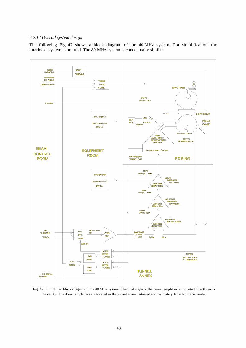
48
6.2.12 Overall system design
The following Fig. 47 shows a block diagram of the 40 MHz system. For simplification, theinterlocks system is omitted. The 80 MHz system is conceptually similar.
Fig. 47: Simplified block diagram of the 40 MHz system. The final stage of the power amplifier is mounted directly ontothe cavity. The driver amplifiers are located in the tunnel annex, situated approximately 10 m from the cavity.

49
7. TRANSVERSE EMITTANCE CONSERVATION AND MEASUREMENT
7.1 Emittance conservation issues
The conservation of the transverse emittance for the LHC beam throughout the injection chain is animportant issue mainly for the following reasons. The performance of a collider is determined by theluminosity,
βπεγ=
n
rev2bb
4
fNkL ,
which is proportional to the number of events per second and thus has to be maximised. This favoursa large particle number per bunch Nb
and a small normalised emittance εn. However, space charge
effects at low energies work against this by limiting the achievable beam brightness Nb/εn. The
strategy is therefore to produce the highest possible brightness beam at low energy and then totransport it through the injector chain by carefully avoiding any performance loss due to emittanceblow-up. More detailed considerations can be found in Chapter 1.
The proton injection chain for the LHC consists of the Linac2, the PSB, the PS and the SPS.The 50 MeV beam coming from the LINAC is injected into the four vertically stacked PSB ringsusing a multi-turn injection. At 1.4 GeV, the four rings are consecutively ejected towards the PS,filling half the PS circumference. After injection of a second batch from the PSB, the beam isaccelerated to 26 GeV/c in the PS and ejected towards the SPS. The emittance budgets along theinjection chain for the different LHC beams are summarised in Table 21.
Table 21LHC initial, nominal and ultimate proton beam intensities and emittances.
Linac PSB PS SPSCommissioningp/LHC bunch 1.7 1010 1.7 1010
p/pulse 180 mA 1.80 1011/ring 1.4 1012 4.1 1012
εn ( = (βγ)rel·σ2/β) 1.0 0.6 (shaving?) 0.8 0.9 (scraping?)Nominalp/LHC bunch 1.1 1011 1.1 1011
p/pulse 180 mA 1.15 1012/ring 9.2 1012 2.7 1013
εn 1.0 2.5 3.0 3.5Ultimatep/LHC bunch 1.7 1011 1.7 1011
p/pulse 180 mA 1.80 1012/ring 1.4 1013 4.1 1013
εn 1.0 2.5 3.0 3.5
The multi-turn injection into the PSB and strong space charge effects lead naturally to thelargest emittance blow-up in the injection chain. It has to be optimised to achieve a beam with therequired high brightness (small emittance). This emittance should then be conserved throughout theinjection chain. Therefore, besides the control of resonances and instabilities, the beam-transfersbetween PSB, PS and SPS are the major concerns. When transferring a beam between two machines,there are three main sources for rms emittance blow-up:
• injection mis-steering:
2
/
/
2
1
β∆α+′∆ββ∆
ε=
εε∆
xx
x,
• betatron mismatch 2
/
/
2
1
ββ∆α+α∆
ββ∆β∆+β
β=εε∆
,

50
• dispersion mismatch
22
/
/
2
β∆α+′∆ββ∆
εσ
=εε∆
DD
Dp .
In the formulae above, α and β are the Twiss-functions in the matched case and ∆α and ∆β are thedeviations due to the mismatch, the same applies for the dispersion function D and D'; σp
= (∆p/p)rms
isthe standard deviation of the relative momentum spread. It should be noted that the emittance blow-up due to mis-steering and dispersion mismatch is inversely proportional to the initial emittance.Thus, these two error sources are particularly important for the LHC beam due to its small designemittance.
7.1.1 Transfer PSB to PS:
The foreseen maximum emittance blow-up between PSB ejection and PS ejection is 0.5 µm(Table 21, nominal). Assuming that 0.2 µm are assigned to effects during acceleration in the PS, theremaining 0.3 µm can be split into three equal parts for the blow-up sources mentioned above and onecan quote typical values for maximum tolerable steering and matching errors between the twomachines. The centre of the straight section 45 in the PS (location of the fast injection kicker) waschosen as reference point for the calculations6. The Twiss-parameters are βx
= 20.3 m, βz = 11.9 m,
αx = αz
= 0, Dx = 3 m, D'
x = 0. It was assumed that the errors are only in position, beta-function and
Dispersion and are zero for the derivatives. The maximum tolerable mis-steering or mis-matches arequoted in Table 22.
Table 22Maximum tolerable steering/matching errors for the transfer PSB to PS:
each effect alone causes an increase in εn of 0.1 µm.
PS-section 45 centre horizontal verticalBeta-function 20.3 m 11.9 mDispersion 3.0 m -Injection mis-steering ∆x = 0.9 mm ∆z = 0.7 mmBetatron mismatch ∆β = 5.7 m ∆β = 3.4 m Dispersion mismatch ∆D = 0.7 m −
The optics presently in use for the transfer between PSB and PS is not well matched in terms ofdispersion. Up to now, this fact was not important but for the LHC beam, with a small transverseemittance and a large momentum spread (σp
= 1.25·10-3), it becomes relevant. To improve on thisside, a modified optics [62] that significantly reduces the dispersion mismatch (while preserving thebetatron matching) is being tested and verified with a view to use it in the future.
In the case of the PSB the fact that there are four rings which need to be recombined imposesadditional difficulties. To minimise the injection oscillations in the PS it is required to individuallycorrect the trajectories of the four bunches. The number of independent correction elements is intheory sufficient, but in practice it is not straightforward to equalise the trajectories from differentrings to better than ± 1 mm. Furthermore, the reproducibility of the trajectories is not guaranteed andtherefore an injection damper will be installed in the PS to provide bunch-by-bunch correction ofthese residual injection errors (see below).
As far as betatron matching is concerned, the vertical dipoles in the recombination sectioncreate optical differences between the rings which cannot be corrected with the present hardware. Theeffect is small but if required it can be reduced by installing a correction quadrupole [63].
6 It should be noted that for the calculation of the emittance blow-up due to mis-steering and dispersion mismatch theunnormalised emittances have to be used.

51
7.1.2 PS injection damper
A mis-steering of less than 1 mm at PS injection leads to a significant emittance increase of the LHC-type beams (see Table 22). The four beams from the PSB, recombined to one and sent in two batchesto the PS, undergo some unavoidable mis-steering because (i) small time-dependent variations ofelements such as power converters or RF feedback loops lead to degrading beam orbits; (ii) the eighthorizontal and vertical kicker magnets in the PSB-PS beam transport suffer from overshoot and flat-top ripple with frequencies of up to ~15 MHz (this latter effect cannot be corrected with steeringdipoles). For these reasons, two injection oscillation dampers, one for each plane, are being built forthe PS. They feature travelling-wave kicker magnets of 6.25 and 12.5 Ω characteristic impedancewith a bandwidth of ~ 20 MHz. Two 3 kW power amplifiers will drive each kicker, which would thenbe capable of reducing a 3 mm initial injection oscillation to ~ 0.5 mm within 100 µs (50 turns).Recent beam observations suggest that these systems, with an overall bandwidth of ~ 20 MHz, wouldbe quite suitable to also tackle transverse head-tail instabilities during the PS cycle, even at lowerpower. As the prototype kickers and power amplifiers are not yet finalised and further machineexperiments are required to fully understand all aspects of the instabilities, the parameters given hereare preliminary.
7.1.3 Transfer PS to SPS:
The beam optics of the TT2/TT10 transfer lines, linking PS and SPS has been reviewed and as aresult the dispersion and the betatron matching could be improved [64]. In addition to that, orthogonaltuning knobs, to minimise the unavoidable residual mismatch were developed [65]. To minimise theblow-up due to injection mis-steering, a new damping system will be installed in the SPS [66].
7.2 Beam diagnostic upgrades in view of LHC beams
The high-brilliance LHC-type beams require close observation of possible emittance blow-up duringacceleration in Linac2, PSB and PS and during transfers from one machine to the next. In view ofthese low-emittance beams several diagnostics instruments have been substantially upgraded while afew new ones have been built in order to cope with new diagnostic requirements.
The PSB has received 2 new Secondary Emission Monitor grids (SEM-grids) close to theinjection septum. In the 1999/2000 shutdown the SEM-grids in the measurement line will beupgraded and a fast blade scanner as well as 8 new wire scanners for profile measurements in the4 rings will be installed. The PS measurement targets have been upgraded and new electronics hasbeen developed for their remote control. In addition, tests are being made in view of the developmentof a non-destructive profile measurement to measure beam profiles during the entire PS accelerationcycle.
7.2.1 SEM-grids at PSB injection
During the 97/98 shutdown 2 new SEM-grids have been installed in the PSB ring 3 in front of theinjection septum. One of the SEM-grids sees the beam arriving from Linac2 while the other isdesigned to observe several turns of the circulating beam.
The SEM-grid in the 50 MeV transfer line is of standard type integrating the pulse generatedby secondary emission during a single passage.It has 48 wires in each plane with a wiredistance of 1 mm. For economic reasons onlythe inner 24 wires are equipped with anamplifier / Analogue to Digital Converter(ADC) readout chain resulting in a resolutionof 1 mm and a coverage of 24 mm. This SEM-grid is used in standard operation now.
The SEM-grid placed in the circulatingbeam uses a very fast (~ 100 ns rise-time)amplifier in conjunction with a 40 MHz ADCwhich converts the wire signals and saves the
0 500 1000 1500 2000time [25ns]
5
10
15
20
wir
enu
mbe
r
Fig. 48 SEMgrid profiles from several turns in Booster ring 3.

52
digital values in an associated 2 k-sample memory.With a revolution time of 2.4 µs at 50 MeVinjection energy approximately 30 turns can beobserved. It has 32 active wires placed at a distanceof 2 mm covering a width of 64 mm. Only ahorizontal wire plane (50 µm wire diameter) isavailable.
A SEM-grid measuring beam profiles on aturn-by-turn basis can observe betatron mismatch.This method will be used with the SEM-grids in thePS. The PSB SEM-grids have been used for initialtest measurements. During several MDs, positionoscillations as well as width oscillations could beobserved. Similar measurements on the PS SEM-grids are planned.
7.2.2 The PSB fast wire scanners
Since 1993, fast wire scanners are used successfully in the PS to measure transverse beam profiles tovery high precision and it was natural to install these devices also in the PSB in order to get consistentmeasurements in both machines. It was known that wire scanners could be used for 1 GeV protonbeams, but their performance at lower energies, especially at 50 MeV injection energy, was doubtful.
Before investing heavily in 10 new wire scanners (1 horizontal and 1 vertical for each of the4 rings + 2 spares) the spare PS wire scanner was mounted in ring 1 of the PSB for investigation.During MDs in 97 and 98 its performance was tested and results compared to other measurementsalready available (BeamScope in the PSB, PSB measurement line and SEM-grids in TT2).
The PS wire scanner uses a scintillator and photomultiplier system in order to detect secondaryparticles created by the interaction of the circulating beam with the passing wire. This method worksfine down to proton energies of a few hundred MeV but fails at very low energies (below the pioncreation threshold). In order to cover the full PSB energyrange we tried to measure the secondary emission currentfrom the wire instead of detecting the secondary particleon the scintillator (Fig. 50).
We obtained very clean profiles even at 50 MeVproton energy. Comparison between profiles taken withthe two detection methods showed no difference. Sincethe test measurements with the spare wire scanner yieldedconvincing results, the TRIUMF laboratory (Vancouver)has been charged to build 10 such devices of which 8 arescheduled to be installed during the 99/2000 shutdown.
7.2.3 The fast blade scanner
Until the fast wire scanners become available in all PSB rings, beam emittance is measured with theBeamScope. This device consists of a set of deflector magnets that drives the beam into a fixedaperture limitation. The beam is scraped away and the beam losses are detected on a DC BeamCurrent Transformer (DCBCT). Since this method modifies the beam orbit, which in turn is correctedby the RF feedback system, doubts existed about the validity of its results in particular for lowemittance LHC-type beams.
A cleaner way of performing the same measurement is to leave the beam in its position andmove the aperture limitation instead. This is done with the fast blade scanner prototype, a device thathas also been constructed at TRIUMF. It consists of a fast moving blade (~ 10 m/s) which traversesthe beam while the losses are observed with the DCBCT. The device is being tested at CERN and isalso scheduled to be installed in PSB ring 1 during the 1999/2000 shutdown. It will allow comparisonmeasurements with the BeamScope and the wire scanners.
500 1000 1500 2000t [25ns]
5
10
15
20
wire mean position
Fig. 49 Position oscillations measured on SEM-gridin Booster ring 3.
0100200300400500600700800
-40 -20 0 20 40Position (mm)
Sig
nal
Fig. 50 Profile taken with photomultiplier (grey,noisy profile) and secondary emission at 50MeV.

53
7.2.4 The PSB measurement line
The PSB measurement line is equipped with 3 SEM-grids per plane, to measure the emittance of thebeam sent to the PS. Their mechanisms are more than 20 years old and would need replacement. Itwas decided that instead of replacing them it would be favourable to have new, higher resolutiongrids installed permanently in the beam. The new grids will consist of a series of wires instead ofribbons to minimise the interaction with the beam. The number of wires per plane has been increasedto 32 and the wire distance decreased to 1 mm for the outer SEM-grid and 0.5 mm for the central one.The analogue electronics chain will be replaced and the digital electronics will use VMEADCs instead of the old CAMAC scanning ADCs. The installation will be done during the99/2000 shutdown.
7.2.5 The PS measurement targets
In addition to the wire scanners, the measurement targets can be used in the PS to measure beamsizes. The target consists of a fork with 2 fingers whose distance can be adjusted. The fork flips intothe beam and beam losses are observed on the DCBCT.
The measurement targets, which can also be used for limiting the aperture, scraping the beamhalo away, were only used manually up to now.
In order to remotely control the devices, the motors adjusting the distance of the fork fingershad to be replaced. New electronics had to be developed giving remote access to its internalparameters (fork finger distance, retention magnet, flip timing etc.)
In addition, an application program controlling the devices, reading the beam loss from theDCBCT and displaying the results in a user-friendly way was developed from scratch. The system iscurrently undergoing its final tests.
7.2.6 Non destructive profile measurement in the PS
Each of the previously described profile measurements is only capable of measuring the profile at asingle instant within the acceleration cycle. It would be very desirable to be able to observe the beamprofile evolution along the acceleration cycle in a continuous manner. This can only be done in a non-invasive way.
First test measurements are being made, using the light emitted from excitation of rest-gasmolecules. In order to increase the light intensity, a gas (Xenon or Argon) is injected into the vacuumchamber thus creating a pressure bump. Test measurements with protons using the fast wire scannerhave shown no significant beam blow-up up to pressures of 10-6 torr. This indicates that futuremeasurements could be done parasitically as long as no heavy ions are accelerated in the machine (thelifetime of heavy ions is reduced drastically by bad vacuum due to stripping and recombinationeffects).
The main question to be answered before constructing a diagnostic device based on lightemission from the rest-gas is the resolution that can be reached by such a detector.
7.3 Other beam diagnostics: new, improved, modified
Not only the emittance and profile measurement devices (Section 7.2), but many other beammeasurement and diagnostics systems in the LHC pre-injector chain of accelerators (Linac2,PSB rings and PS) underwent a close scrutiny to highlight the problems and to propose solutions forthe essential elements of the LHC filling scheme. While the changes required at the Linacs wereminimal, close attention had to be paid to the existing systems in the PSB rings, PS and the beamtransfer tunnel TT2. Many systems had to be improved and modified, essentially to cater for the newRF harmonics in both the PSB and the PS.
In 1993, the successful testing of the ideas behind the LHC filling scheme had shown that theexisting PSB closed orbit measurement system was able to handle the new RF beam structures to alarge extent, though perhaps not perfectly. No major changes have been carried out in this system for

54
the purposes of this study, however, it is envisaged that the PSB closed orbit system will undergo ahardware upgrade to perfectly match the beam characteristics in the PSB in the LHC era.
A completely new tune measurement system [67, 68] but based on the existing “Q-kickers”[69] for each of the four PSB rings has been developed, using synchronised beam excitation with asmall-amplitude, one-turn kick and obtaining fast fourier transformation spectra using a DSP Board.The kicker pulser length is gated to the varying revolution period (1670 ns at injection to 570 ns atextraction) and similarly, the ADC is synchronised to sample the signals at four times the revolutionfrequency. The system is fully integrated into the standard VME based Controls System. Tunemeasurements may be performed every10 ms in both planes for each of the 4 ringsin the PSB, through the full accelerationramp (50 MeV – 1.4 GeV) in the nominal1.2 s PSB cycle (Fig. 51). Measurementshave shown that the amplitudes of thetransverse oscillations generated by theexisting, small-amplitude pulser aresufficiently small not to affect the beamemittance. Hence, tune measurements maybe carried out all the time without affectingthe beam. However, if it is necessary toimprove the measurements near 1.4 GeV, anew, controllable, larger amplitude kickerpulser is foreseen for implementation in thenear future.
For the PSB to PS transfer channel, the digital system used for the position pickups neededminor changes to cater for the new RF structure of the beam.
In the PS Ring, substantial work had to be carried out in the closed orbit and trajectorymeasurement system. The PS had traditionally a trajectory measurement system based onmeasurement of beam position over 2 consecutive turns near injection as well as at any instant in theacceleration cycle. Given the new RF harmonics and gymnastics in the PS required for LHCoperation, considerable hardware and software additions and modifications were necessary. This hasled to continuity with the traditional trajectory measurements as well as availability of additionalcapabilities as required for the double-batch injection, new beam structures and so forth, right up to,but not including measurements at the extraction of 84 bunches. The new trajectory and closed orbitsystem is fully integrated in the controls system and is spread over 3 networked VME crates [70-72].
For the beam current transformers in the PS Ring, the major implication has been the advent ofdouble-batch filling from the PSB. However, most of the changes required are at the level of thetiming and specific equipment (ADC channels, triggers and specific software) to provide additionalmeasurement capabilities for this mode of operation. For example, the PS Ring DCBCT required anextra facility to permit measurement of the second batch, in addition to first one already injected onthe same PS cycle. Similar changes are reflected in other systems like the one used in the PS formeasuring beam current in each of the first six turns at injection for protons.
In the beam transfer line TT2 between the PS and SPS, two new electrostatic wide-band pick-ups have been developed and installed to observe the particular characteristics of the LHC type ofbeam (84 bunches, 4 ns width, 25 ns separation). The pick-ups are judiciously spaced apart in sections208 and 228 (to determine position and angle of each of the 84 bunches) and have electrodes based onan earlier design for a special 200 kHz - 300 MHz wide-band pick-up in the section 98 of the PS ring.With new electronics purposely developed, the bandwidth of the pick-ups has been extended to~ 6 kHz to 400 MHz. The signals from the electrodes as well as the sum signals are permanentlyconnected to the analogue observation system and are routinely used for study purposes. The pick-upsalso prove useful in observing other types of beams extracted from the PS to the TT2 transfer line,particularly the classical proton 5-turn extraction beam for the SPS. Further experience with thisequipment has to be obtained before connecting it to the standard control system.
Fractional Tune in Ring3 for LHC beam in the PSB (measured on 12Nov99; 1.3E12 protons in Ring3)
0
0.05
0.1
0.15
0.2
0.25
0.3
0.35
0.4
0.45
0 100 200 300 400 500
Time in ms from 50 MeV Inj to 1.4 GeV Flattop
Fra
ctio
nal
Tun
ehorizontal
vertical
Fig. 51 PSB tune measurement.

55
For beam current measurements in the TT2 transfer line, the LHC type of beam does not poseany particular problems. However, to supplement measurements from the existing fast beam currenttransformer TRA203, the lead ion transformers TRA372 and TRA379 have been modified to measureproton beams. These transformers, built for the lead ion operation from 1994 onwards, measure thestripping efficiency and are installed just at the switching of the beam from the PS controlled TT2beam line to the SPS controlled TT10 beam line. A new transformer, TRA386, has been installedbefore the D3 beam dump at the end of TT2 to verify consistency of measurements under alloperations. The fast beam current transformer measurements are now completely uniform withautomatic range switching between the three ranges (up to 4·1010, 4·1010 - 1·1012, 1·1012 - 4·1013 electriccharges) and satisfying all known requirements for the SPS and LHC needs.
8. POSSIBLE FUTURE DEVELOPMENTS
8.1 Means to achieve the specified longitudinal beam parameters
8.1.1 Status of performance
Experiments have shown that the longitudinal beam characteristics are degraded at 26 GeV/c in thePS during the debunching-rebunching process (see Chapter 6). At the nominal intensity thelongitudinal emittance blows-up by 40 % so that bunches end-up 20 % too wide in length and energyspread. An instability is responsible for this effect which could be caused by the high orderresonances in the 114 MHz cavities used for lepton acceleration. Although the removal of thesecavities is planned after the year 2000, the debunching-rebunching process will remain sensitive toperturbations and a more robust procedure is worthwhile considering.
Moreover the nominal scheme provides a train of 84 bunches without any gap for the rise-timeof the fast ejection kicker [47], so that 3 bunches are either lost or subject to large transverseoscillations and subsequent filamentation in the SPS.
8.1.2 Multiple splitting
The proposal [48] is to avoid debunching and to change the number of bunches using multiplesplitting operations as represented in Fig. 52.
Captured on harmonic 7 in the PS, thebunches are split in three at 1.4 GeV usingappropriate amplitude and phase parameterson three groups of cavities operating onharmonics 7, 14 and 21, respectively. Aspredicted from simulation results (Fig. 53)and as observed during recent machineexperiments in the PS (Fig. 54), that processpreserves longitudinal emittance.
Bunched on harmonic 21, the beam isthen accelerated up to 26 GeV/c where eachbunch is split twice in two using the processwhich has been demonstrated in regularoperation. A new 20 MHz 20 kV RF systemis required at that stage. Finally eachoriginal bunch has been split in 12, and 84bunches are created if all of the 7 bucketsare filled.
Triple splitting@ 1.4 GeV
Double splitting @ 26 GeV:
PS injection::6 buncheson h=7 in 1 turn
Em
pty
buck
et
Acceleration of18 buncheson h=21
PS ejection:72 buncheson h=84 in 1 turn
Fig. 52 Generation of the bunch train for LHCwithout debunching-rebunching.
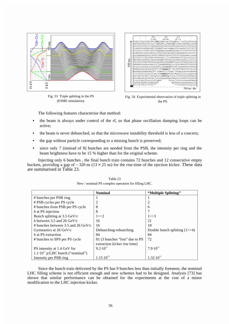
56
The following features characterise that method:
• the beam is always under control of the rf, so that phase oscillation damping loops can beactive;
• the beam is never debunched, so that the microwave instability threshold is less of a concern;
• the gap without particle corresponding to a missing bunch is preserved;
• since only 7 (instead of 8) bunches are needed from the PSB, the intensity per ring and thebeam brightness have to be 15 % higher than for the original scheme.
Injecting only 6 bunches , the final bunch train contains 72 bunches and 12 consecutive emptybuckets, providing a gap of ~ 320 ns (13 × 25 ns) for the rise-time of the ejection kicker. These dataare summarised in Table 23.
Table 23New / nominal PS complex operation for filling LHC.
Nominal “Multiple Splitting”# bunches per PSB ring 1 1# PSB cycles per PS cycle 2 2# bunches from PSB per PS cycle 8 6h at PS injection 8 7Bunch splitting at 3.5 GeV/c 1=>2 1=>3h between 3.5 and 26 GeV/c 16 21# bunches between 3.5 and 26 GeV/c 16 18Gymnastics at 26 GeV/c Debunching-rebunching Double bunch splitting (1=>4)h at PS extraction 84 84# bunches to SPS per PS cycle 81 (3 bunches “lost” due to PS
extraction kicker rise time)72
PS intensity at 1.4 GeV for1.1·1011 p/LHC bunch (“nominal”)
9.2·1012 7.9·1012
Intensity per PSB ring 1.15·1012 1.32·1012
Since the bunch train delivered by the PS has 9 bunches less than initially foreseen, the nominalLHC filling scheme is not efficient enough and new schemes had to be designed. Analysis [73] hasshown that similar performance can be obtained for the experiments at the cost of a minormodification to the LHC injection kicker.
Fig. 53 Triple splitting in the PS(ESME simulation).
Fig. 54 Experimental observation of triple splitting inthe PS.

57
8.2 Other improvements
8.2.1 Bunching factor at low energy
The space charge effects at low energy limit the ultimate transverse beam brightness of the beam. TheLaslett tune-shift being inversely proportional to the bunching factor Bf
(Bf = mean beam current
divided by peak beam current), the techniques which help reduce the peak beam current are beneficialfor achieving and keeping small transverse emittances.
A classical solution is to use a second harmonic RF to decrease the longitudinal focussing forthe particles at the core of the bunches and obtain “flat bunches”. This is in regular operation in thePSB since the end of the eighties, and it has also been implemented as part of the preparation of thePSB for LHC. However that technique is not applicable to the PS which does not have enough RFsystems to support such a mode of operation.
Another solution is to modify the distribution of particles in the bunch and make it hollow, sothat the line density has a flat top although using a single harmonic RF. If such characteristics areobtained at injection energy in the PSB, both the PSB and the PS will profit from reduced Lasletttune-shifts. Various methods have been tried and recent experimental results are veryencouraging [74].
8.2.2 Special beam time structure for handling electron clouds in the LHC
Electron multipactoring has recently been diagnosed as a dominant contributor to the heat load to theLHC cryogenic system, potentially limiting drastically the machine performance [75]. Among themany actions envisaged to solve the problem, a number of them require the beam time structure to bemodified, either doubling the distance between bunches or introducing more gaps in the bunch train.
The multiple splitting technique of Section 8.1 is extremely flexible. It offers severalpossibilities of changing the bunch train in ways which could not be achieved with the nominaldebunching-rebunching procedure.
ACKNOWLEDGEMENTS
The authors express their gratitude for the continuous managerial support of A. Astbury, Director ofTRIUMF, L. Evans, CERN LHC Project Leader, K. Hübner, CERN Director of Accelerators, andD.J. Simon, former CERN PS Division Leader. The way they removed problems in the spirit ofmutual understanding made this CERN-TRIUMF joint venture so successful.
Amongst their many other colleagues in TRIUMF and the CERN Divisions EST, LHC, PS, SLand ST, the authors would like to especially acknowledge the help of J.M. Cravero, M. Corcelle,L. Ellstrom, D. Evans, H. Fiebiger, W. Fritschi, M. Georges, M. Haase, P. Harmer, M. Hourican,B. Keeley, E. Knight, M. Lindroos, A. Lombardi, A. Marmillon, S. Milner, F Pedersen, R. Scrivens,G. Simonet.

58

59
APPENDIX: LIST OF RELEVANT PARAMETERS
Machine/Parameter Unit Commissioning
Nominal /common
Ultimate Comments
RFQ Four-vanes typeInput energy keV 90RF frequency MHz 202.5Output energy keV 750Output intensity during pulse mA 200Beam pulse length µs 120Transverse emittances εn µm 0.6 εn = (βγ) σ2/βtwiss
∆p/p (2σ) 10-3 17.5Repetition time s 1.2LINAC 2 Alvarez typeInput energy MeV 0.75Number of tanks 3 10/30/50 MeVRF frequency MHz 202.5Output energy MeV 50Output intensity during pulse mA 180Beam pulse length µs >30 100 µs achievedTransverse emittances εn µm 1.2 Equal both planes∆p/p (2σ) 10-3 1.5Repetition time s 1.2PSB (4 rings)Radius m 25 ¼ of PSNumber of lattice periods 16 lattice B-F-D-F-BMax. βx, βy, D (dispersion) m | 7.6, 19.0, 1.5 |γt ~4.1Injection energy MeV 50
Main magnet field T 0.1256Main magnet current A 584Number of inj. turns ~1 ~2 ~3 Hor. betatron stackingQx/Qy 4.27/5.50 4.26/5.40 4.27/5.45 Subject to optimisationrevolution period µs 1.67
RF h=1 system voltage/turn kV 8 1 cavity/ringFrequency MHz 0.6-1.8h=2 system voltage/turn kV 8 1 cavity/ring for bunchFrequency MHz 1.2-3.9 flatteningNumber of bunches/ring 1
Ejection energy GeV 1.4Momentum GeV/c 2.141Main magnet field T 0.867Main magnet current A 4030Qx/Qy 4.17/5.23Revolution time ns 572Bunches/ring 1
Beam intensity/ring 1012 0.18 1.15 1.8 = 10.5 LHC bunchesεn µm 0.6 2.5 2.5Bunch length ns 190∆p/p (2σ) 10-3 2.5Bunch area eVs 1.45Bunch area/LHC bunch eVs 0.14
Repetition time s 1.2Number of pulses to fill PS 2

60
Machine/Parameter Unit Commissioning
Nominal /common
Ultimate Comments
PSRadius m 100Number of lattice periods 25 (FD)O(DF)ONumber of superperiods 10Number of magnets 100 Combined functionMax. βx, βy, D (dispersion) m 22.3, 22.6, 3.0γt 6.1Injection energy GeV 1.4
Momentum GeV/c 2.14Main magnet field T 0.101Main magnet current A 406?Qx/Qy 6.15/6.28 Subject to optimizationRevolution period µs 2.288Flat bottom length s 1.2
# PSB batches per injection 2 Each batch fills ½ PSRepetition time (LHC cycle) s 3.6RF accelerating system Relevant for LHC beam
Number of cavities 12 Ferrite-loadedMax. voltage/turn kV 240Frequency range MHz 3-10
RF fixed-frequency systems40 MHz numb. of cavities 2 Bunch spacing 25 ns
Voltage/turn kV 60080 MHz numb. of cavities 3 Bunch shortening 4 ns
Voltage/turn kV 900Longitudinal parameters
# bunches after injection 8RF harmonic at injection 8
bunch splitting momentum GeV/c 3.56 h=8 => 16# bunches after splitting 16Bunch area eVs 1.0 Controlled blow-upBunch area/LHC bunch eVs 0.19
debunch-rebunch moment. GeV/c 26Duration of process ms 150After rebunch.: # of bunches 84 h=84
Bunch length ns 12∆p/p (2σ) 10-3 0.7Bunch area eVs 0.35
Bunch rotation: bunch length ns 4∆p/p (2σ) 10-3 2.2Bunch area eVs 0.35
Ejection energy GeV 25.1Momentum GeV/c 26Main magnet field T 1.256Main magnet current A 5140?Revolution time µs 2.1
Beam intensity p/pulse 1012 1.4 9.2 14.3 84 LHC bunchesIntensity/LHC bunch 1011 0.17 1.1 1.7εn µm 0.8 3 3
PS pulses per SPS cycle 3

61
REFERENCES
[1] P. Lefèvre, T. Petterson (Ed.), The Large Hadron Collider, Conceptual Design;CERN/AC/95-05(LHC), Oct. 1995.
[2] F. Blas et al., Conversion of the PS complex as LHC proton pre-injector, Proc. PAC ’97,p. 973, Vancouver, Canada, 1997.
[3] P. Collier (editor), The SPS as injector for LHC, conceptual design, CERN-SL-97-07, DI,1997.
[4] The PS Staff, reported by K. Schindl, Partial test of the PS complex as LHC proton pre-injector, Proc. EPAC ’94, p. 500, London, UK, June 1994.
[5] K. Schindl, Conversion of the PS complex as LHC proton pre-injector: Project proposal,PS/DI/Note 94-17, 1994.
[6] C.E. Hill, A.M. Lombardi, E. Tanke, M. Vretenar, Present Performance of the CERN ProtonLinac, Proc. 1998 Linear Accelerator Conference, Chicago, ANL-98-28, p. 427, 1998.
[7] C.E. Hill, A.M. Lombardi, W. Pirkl, E. Tanke, M. Vretenar, Performance of the CERNLinac2 with a High Intensity Proton RFQ, Proc. 1994 Linear Accelerator Conference,Tsukuba, p. 175, 1994.
[8] E. Tanke, Realignment of the Linac2 LEBT During the 1994/1995 Machine Shutdown, CERNPS/HI-Note 95-10 (MD), 1995.
[9] J.L. Vallet, M. Vretenar, M. Weiss, Field Adjustment and Beam Analysis of the High-Intensity CERN RFQ, Proc. EPAC ’90, p. 1234, Nice, France, 1990.
[10] M. Vretenar, Field Emission Measurements on RFQ2 and Recalibration of the Vane Voltage,CERN PS/RF/Note 97-11 (MD), 1997.
[11] A.V. Feschenko, A.V. Liiou, P.N. Ostroumov, O. Dubois, H. Haseroth, C. Hill, H. Kugler,A. Lombardi, F. Naito, E. Tanke, M. Vretenar, Study of Beam Parameters of the CERNProton Linac using a three dimensional Bunch Shape Monitor, Proc. 1996 Linear AcceleratorConference, Geneva, CERN 96-07, 1996.
[12] H. Ullrich, Proposal for the upgrade of the Booster main magnet power supply, CERNPS/PO/Note 95-02(tech.), 1995.
[13] O. Bayard, Description du filtre d’harmoniques sous station Jura, CERNLABII/PS/OB/EEK/ Tech.Note-72 1, 1972.
[14] J. Pedersen, Technical specification for a 18 Mvar, 18 kV thyristor controlled reactor,CERN ST-IE-PI/96-193, 1996.
[15] H. Ullrich, Rectifier double transformers for upgrading the Booster main magnet supply,CERN PS/PO/Note 95-23 (Spec.), 1995.
[16] T. Salvermoser, New electronics for the regulation and timing of the Booster main powerconverter, CERN PS/PO/Note 96-23 (Min.), 1996.
[17] H. Ullrich, 12 phase thyristor power converters with passive and active filter modulated 0 to300 A, 520 V, CERN PS/PO/Note 95-24 (Spec.), 1995.
[18] H. Fiebiger, F. Gendre, T. Salvermoser, Modification of Booster magnet circuit groundinglayout, CERN PS/PO Note 97-07(Tech.), 1997.
[19] M. Benedikt, C. Carli, Operation of the CERN PS-Booster above 1 GeV - Saturation effectsin the main bending magnets and required modifications, CERN/PS 98-059 (OP), 1998.
[20] T. Salvermoser, Specification of a switch mode power supply, CERN PS/PO/Note 98-54(Spec), 1998.
62
[21] H. Fiebiger, F. Gendre, T. Salvermoser, H. Ullrich, Commissioning Booster Trim Supply,CERN Memo 19-3-99, 1999.
[22] F. Völker, Soft-Switched Mode DC Power Converters for the 1.4 GeV PSB Beam Transfer-line Magnets, CERN PS/PO Note 96-01 (Spec), 1996.
[23] F. Völker, Soft-Switched Mode DC Power Converters for the 1.4 GeV PS-Booster BeamTransfer-line magnets, CERN PS/PO Note 98-08 (Spec), 1998.
[24] M. Georges, G. Simonet, Les Nouvelles Alimentations des Lignes de Transfert PSB-PS etPSB-ISOLDE, CERN PS/PO Note 98-44, 1998.
[25] J.P. Royer, High current with high precision flat-top capacitors discharge power convertersfor pulsed septum magnets. CERN/PS/95-13 (PO), 1995.
[26] J.P. Royer, Technical specification of the capacitor discharge power supplies for septummagnet of the transfer line PSB-PS, CERN PS/PO/SPEC94-08, 1994.
[27] J.M. Cravero, J.P. Royer, The new pulsed power converter for the septum magnet in the PSstraight section 42, CERN PS/PO/ note 97-03, 1997.
[28] G.S. Clark, A.J. Otter, P. Reeve, Magnets for the CERN PS Booster transfer line, Proc.PAC ’97, Vancouver, Canada, 1997.
[29] M.J. Barnes et al., New Magnets for the transfer line PSB-CPS, CERN SL-Note-98-052 MS,1998.
[30] D. Evans, M.J. Barnes, B. Evans, R. Nussbaumer, Rotating coil and data acquisition systemfor measuring CERN beam transferline quadrupole magnets, Proc. of IMMW 10, Batavia,Illinois, USA, 1999.
[31] M.J. Barnes, G.S. Clark, M. Sassowsky, Three dimensional field calculations compared tomagnetic measurements for CERN PSB-CPS transfer line magnets, Proc. PAC ’99, NewYork, USA, 1999.
[32] A. Brückner, Kicking protons, fast and cheap, 1971 US Particle Accelerator Conference,Chicago, 1-3 March, 1971.
[33] A. Brückner, A non-linear step-pulse steepening delay line, CERN Yellow Report 68-25, July1968.
[34] A. Fowler, The PSB ejection bumper system for LHC, CERN PS-CA Note 99-22,1999.
[35] B. Dumas et al., PSB ME 10.-19.7.1996: Cooling water in tunnel +70C, PS/HI/Note 96-10(ME), 1996.
[36] W. Van Cauter, Adaptation des systèmes de refroidissement et climatisation du Booster envue du LHC, CERN ST-CV/96.061/WVC/bm, June 1996.
[37] R. Cappi, R. Garoby, S. Hancock, M. Martini, J.P. Riunaud, K. Schindl, H. Schönauer, Beamsin the PS complex during the LHC era, CERN/PS 93-08 (DI), 1993.
[38] U. Bigliani et al, The RF Acc. Syst. for the CERN PS Booster, IEEE Trans. Nucl. Sci. NS-18,No3, p.233, 1971.
[39] J.E. Griffin, G. Nicholls, A review of Some Dynamic Loss Properties of NiZn Accel. RFSystem Ferrite, IEEE Trans. Nucl. Sci., Vol. NS-26, No.3, June 1979.
[40] R. Garoby et al, RF System for High Beam Intensity Acceleration in the CERN PS, CERN/PS89-28 (RF), 1989.
[41] T. Bohl, T. Linnecar, E. Shaposhnikova, W. Sinclair, U. Wehrle, Study of controlledlongitudinal blow-up in the SPS using the 800 MHz rf system, CERN SL-MD Note 221.
[42] J. Bento, A. Blas, C. Carli, M. Chanel, J.P. Terrier, PSB vacuum flanges impedancemeasurement, to be published.

63
[43] A. Hofmann, F. Pedersen, Bunches with local elliptic energy distributions, IEEE transactionson nuclear science, Vol. NS-26, No.3, June 1979.
[44] F. Pedersen, F. Sacherer, Theory and performance of the longitudinal active damping systemfor the CERN PS Booster, CERN/PS/BR/77-8, February 1977.
[45] R. Garoby, Organisation and control of the PS low level RF in 1998, CERN PS/RF/ Note 97-19, 1997.
[46] R. Garoby, A Non-Adiabatic Procedure in the PS to Supply the Nominal Proton Bunches for theLHC into 200 MHz RF Buckets in SPS; CERN PS/RF/Note 93-17, Nov. 1993.
[47] R. Garoby, Longitudinal limitations in the PS complex for the generation of the LHC protonbeam, Particle Accelerators, Vol. 58, Numbers 1-4, pp. 121-136, 1997.
[48] R. Garoby, Status of the nominal proton beam for LHC in the PS, Proceedings of theWorkshop on LEP-SPS Performance, Chamonix 1999, pp. 94-98, 1999.
[49] R. Garoby, Requirements to the PS RF systems for filling the LHC with 25 ns spacingbetween bunches; CERN PS/RF/Note 93-04, Mar. 1993.
[50] A.J. Hatch, Suppression of Multipactor in Particle Accelerators; NIM 41, pp. 261–272, 1966.
[51] W.D. Kilpatrick, Criterion for Vacuum Sparking Designed to Include Both rf and dc; Reviewof Scientific Instruments 28, No. 10, Oct. 1957.
[52] R. Garoby, D. Grier, E. Jensen, A. Mitra, R.L. Poirier, The PS 40 MHz Bunching Cavity;CERN/PS/97-039, Proc. PAC ’97, Vancouver, Canada, 1997.
[53] E. Jensen, R. Hohbach, A.K. Mitra, R.L. Poirier, Higher-Order Mode Damping of the CERNPS 40 MHz Cavity; Proc. EPAC ’96, Sitges, Spain, 1996.
[54] A.K. Mitra: Servo Tuner for 40 MHz Cavity, CERN PS/RF/Note 96-20, Jul. 96.
[55] A.K. Mitra, R.L. Poirier, E. Jensen, Coarse and Fine Tuners for the CERN PS 40 MHzBuncher Cavity; Proc. PAC ’97, Vancouver, Canada, 1997.
[56] I. Enchevich, R.L. Poirier, Perpendicularly Biased Ferrite Tuner for the CERN LHC cavity;TRIUMF Design Note TRI-DN-97-28, Dec. 1997.
[57] A.K. Mitra, R.L. Poirier, R. Losito, Measurements at TRIUMF on a 80 MHz Cavity Modelfor the CERN PS Upgrade for LHC; Proc. PAC ’97, Vancouver, Canada; 1997.
[58] D. Grier, E. Jensen, R. Losito, A.K. Mitra, The PS 80 MHz Cavities; CERN/PS/98-021(RF),Proc. EPAC ’98, Stockholm, Sweden, 1998.
[59] A.K. Mitra, S. Rose, Higher-Order-Mode Damping of the CERN 80 MHz Cavity; TRIUMFDesign Note TRI-DN-97-8, Apr. 1997.
[60] R. Losito, Design report for the capacitive tuners of the 80 MHz cavity, CERN PS/RF/Note96-32, Dec. 1996.
[61] For some details of the mechanical construction see e.g.: N. Mezin, Cavités RF 40 et 80 MHzpour PS-LHC,http://www.cern.ch/CERN/Divisions/EST/MF/ACTIVITES/v_cavites_rf_ps_lhc.html
[62] M. Martini, T. Risselada, K. Schindl, Measurement of betatron and dispersion matchingbetween Booster and PS, CERN PS/AP Note 91-13, CERN, 1991.
[63] M. Benedikt, A. Jansson, M. Sassowsky, Proposal for a quadrupole correction magnet in theBooster recombination section, PS/OP/Note 99-18, CERN, 1999.
[64] K. Hanke et al, Measurement and optimisation of the PS-SPS transfer line optics, Proc.PAC ’99., p. 1282, New York, USA, 1999.
[65] G. Arduini, K. Hanke, Tuning knobs for the PS-SPS transfer line, Proc. PAC ’99, p. 1284,New York, USA, 1999.

64
[66] W. Höfle, Towards a transverse feedback system and damper for the SPS in the LHC era,Particle Accelerators, Vol. 58, 1997.
[67] A. Chapmann-Hatchett, V. Chohan, E.T. D’Amico, Tune Measurement for the CERN ProtonSynchrotron Booster Rings using DSP in VME, Proc. PAC ’99, New York, USA, 1999.
[68] M. Gasior, J.L. Gonzalez, New Hardware of the tune measurement system for the ProtonSynchrotron Booster Accelerator, CERN PS/BD/Note 99-10, Sept. 1999.
[69] H. Koziol, Q-measurement on the PS Booster, CERN MPS/INT/BR 74-14, 1974.
[70] J.L. Gonzalez, Specification for VME CODD Synchronisation, CERN PS/BD/Note 98-05(Tech.), July 1998.
[71] T. Baglin, High Sensitivity Amplifiers for PS Pick-ups, CERN PS/BD/Note 98-06 (tech.),July 1998.
[72] M. Ludwig, The Synchronisation for the PS Closed Orbit Measurement System: Real timesoftware development and implementation, CERN PS/BD/Note 99-03(tech.), March 1999.
[73] J.M. Jowett, Collision Schedules and Bunch Filling Schemes in the LHC, LHC Project Note179.
[74] A. Blas, S. Hancock, S. Koscielniak, M. Lindroos, F. Pedersen, New Technique for BunchShape Flattening, Proc. PAC 99, New York, USA, 1999.
[75] V. Baglin et. al., Beam-induced electron cloud in the LHC and possible remedies, LHCProject Report 187, 1998.