the premium system for professional tool presetting and
TRANSCRIPT

venturion
The Premium System for Professional Tool Presetting and Measuring
02 | 03
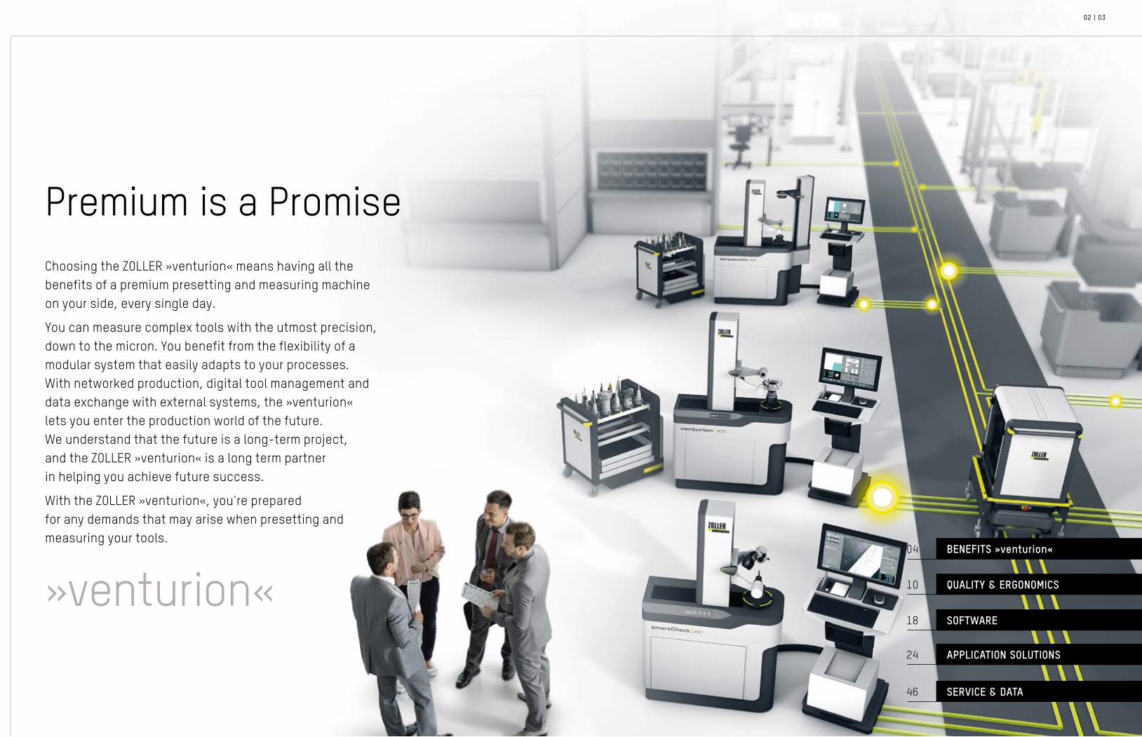
Choosing the ZOLLER »venturion« means having all the benefits of a premium presetting and measuring machine on your side, every single day.
You can measure complex tools with the utmost precision, down to the micron. You benefit from the flexibility of a modular system that easily adapts to your processes. With networked production, digital tool management and data exchange with external systems, the »venturion« lets you enter the production world of the future. We understand that the future is a long-term project, and the ZOLLER »venturion« is a long term partner in helping you achieve future success.
With the ZOLLER »venturion«, you're prepared for any demands that may arise when presetting and measuring your tools.
Premium is a Promise
QUALITY & ERGONOMICS
SOFTWARE
APPLICATION SOLUTIONS
BENEFITS »venturion«04
10
18
24
SERVICE & DATA46
»venturion«

»venturion 600«
»venturion 450«
»venturion 600«
»venturion 800«
04 | 05
Elegant and RobustThe ZOLLER »venturion« is the best teammate you can have. This premium presetting and measuring machine has a robust body consisting of a light alloy specifically developed for measuring machines. Equipped with exclusively high quality, brand-name components with exceptional craftsmanship, nothing compares to the »venturion«.
This precision machine can be used in a number of configurations with a wide variety of additional options, meaning even the highest workload can be handled with ease. Its robust design makes the ZOLLER »venturion« equally suited for a climate-controlled room as it is for the shop floor, right next to the CNC machine.
Technical Data: »venturion«Maximum Tool Length Z Measuring Range X Axis Maximum Tool Diameter D Maximum Snap Gauge Diameter D
»venturion 450«17.72 / 24.41 / 32.28 " (450 / 620 / 820 mm)
8.27 / 12.20 " (210 / 310 mm) 16.54 / 24.41 " (420 / 620 mm) 3.94" (100 mm)
»venturion 600«23.62 / 31.5 / 39.37 " (600 / 800 / 1.000 mm)
11.81 / 15.75 " (300 / 400 mm) 23.62 / 31.5 " (600 / 800 mm) 7.87 / 3.94 " (200 / 100 mm)
»venturion 800«23.62 / 31.5 / 39.37 / 47.24 / 55.12 / 62.99 " (600 / 800 / 1,000 / 1,200 / 1,400 / 1,600 mm)
19.69 / 23.62 " (500 / 600 mm) 39.37 / 47.24 " (1,000 / 1,200 mm) 7.87 / 0 " (200 / 0 mm)

06 | 07
Maximum Process ReliabilityProcesses must be as precise and reliable as the measurements on which they are based. In a »venturion«, electronics, mechanical components and the ZOLLER »pilot« measuring software work closely together to rule out measurement and data transfer errors. This guarantees maximum process reliability.
Automatic Zero Point Monitoring: Prevents Machine Crashes
The software function Automatic Zero Point Monitoring in the »pilot« measuring machine software and the high-precision »ace« spindle work together to ensure that the zero point is automatically selected after the adapter tool post is changed, ensuring safer machines.
Automatic Production Data Acquisition: Quick System Check
The software module »fingerprint« in »pilot« continuously checks at defined intervals whether all system components are functioning. The software detects errors before they occur and guarantees that your »venturion« presetting and measuring machine runs smoothly.
Statistics provide information on how often and by whom measurements are carried out on your machine. This data can be used to optimize processes, for planning purposes and to increase machine utilization.
Automatic Data Transfer: Error-free and Process-reliable
The best way to continue working without manual data entry is to ensure all actual tool data is correct and readily available. »venturion« can be integrated into your network and, if desired, transmits all relevant data to your CNC machines in a control-specific manner.

08 | 09
Considerably More ProfitIt's simple: With preset tools, you reduce set-up times on the machines and therefore increase productivity. With optimally set tools, you achieve longer tool life, and with defined outer contours you avoid machine crashes entirely.
Plus, the digital transmission of your tool data guarantees secure, error-free data input. Thanks to the machine's high quality, brand-name components, with the »venturion«, you get a reliable partner for years to come, which reduces maintenance costs to a minimum. In short: with the »venturion«, you increase the efficiency of your production process.

10 | 11
You may have seen me before on the certificate of approval on your ZOLLER machine. Every ZOLLER employee who assembles a ZOLLER machine has their name and picture on the certificate. We do this because we rely on the quality of our work. We know how important quality is, what it means, and how to ensure that a quality product is what you get. At ZOLLER, we use the best components in every machine we build. Combine that with our attention to detail and our decades of experience, and you are left with a product, and a measurement partner, you can rely on.
For Quality I Give Everything – Every Day.
Christian Hantke, Assembly Technician at ZOLLER

12 | 13
THK Guideways – smooth-running and precise-ly aligned – the ideal base for machine towerand optics carrier. With THK guideways, thetower and carrier are correctly alignedautomatically.
Heidenhain Glass Scales – glass scales in the X, Z and Y axis enable reproducible and reliable position determination with optical means in the μm range.
Bosch/Festo Pneumatics – for the reliable operation of pneumatic functions, such as the power-clamping functions on the spindle.
Highest Quality for Long-lasting Precision
TÜV approved
Optics with Industrial Camera – the high-quality camera has additional lenses and captures every detail – optionally with higher resolution. The strong incident light optimally illuminates edges and steep flanks. The camera and incident light unit are specially protected.
Uhing Linear Drives, Clamping Elements – the basis for correct measurements: The tower is both easy to move and to securely and accurately clamp and tension.
Cable Carriers – for reliable functionalitydespite continuous load, as cables cannotget caught, ripped free or kinked.
Machine Base in the Z and X Axes – are made of a light metal alloy specifically designed to absorb the weight and the forces of the tools in order to measure them reliably every time.
Stable Machine Base – the base of the machine: pneumatics and electronics are housed here. Everything is laid out with sufficient space for accessibility and optimal ventilation.
Machine Tower – aligned to the spindle for precise measurement results.
Machine Control with Industrial TFT Monitor – specially designed to process the amount of data quickly or to call up the extensive programs and measurement sequences immediately. The monitor's razor-sharp display characteristics are a true advantage.
»ace« High Precision Spindle – high precision spindle system with clamping element guarantees the μm accurate holding and clamping of tools. The universal adapter tool post allows adaptation to any tool holding system.
ZOLLER consistently focuses on quality: Thanks to high quality brand-name compo-nents and process-reliable assembly. You can rely on a long service life of your ZOLLER machine and the highest long-term precision.
Every »venturion« machine is tested according to IEC 61010-1.
Verifiable and certified product safety
14 | 15
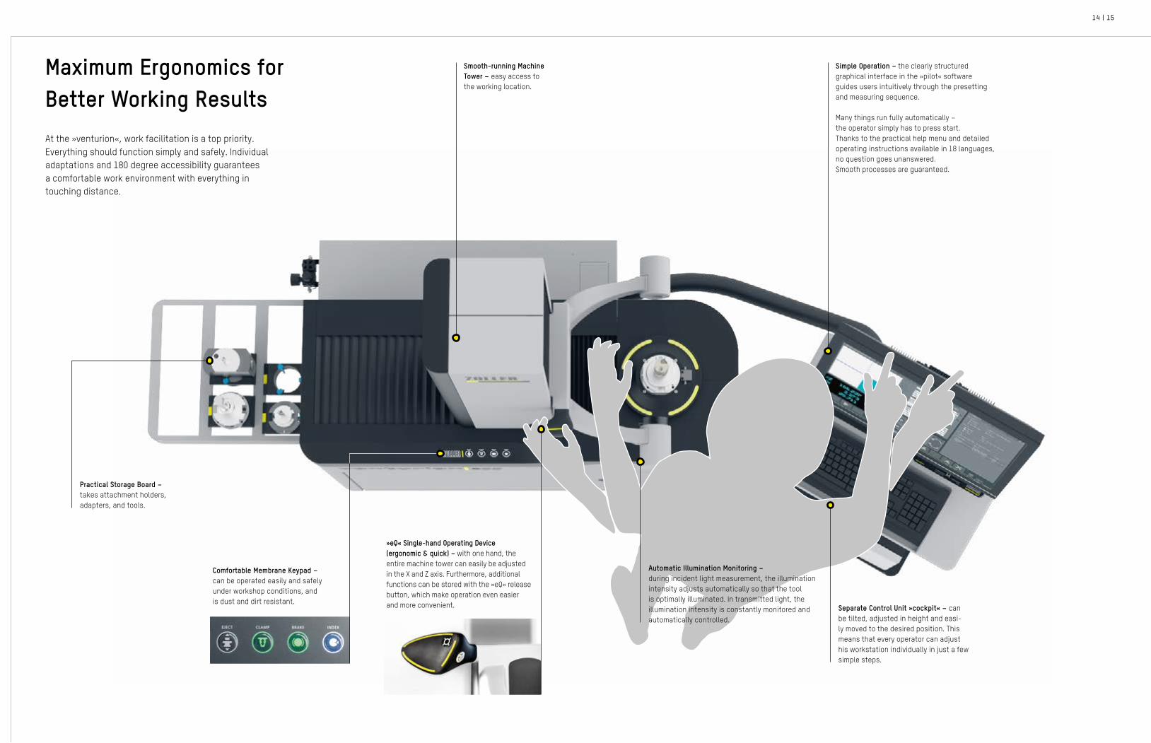
Maximum Ergonomics for Better Working ResultsAt the »venturion«, work facilitation is a top priority. Everything should function simply and safely. Individual adaptations and 180 degree accessibility guarantees a comfortable work environment with everything in touching distance.
Comfortable Membrane Keypad – can be operated easily and safely under workshop conditions, and is dust and dirt resistant.
Smooth-running Machine Tower – easy access to the working location.
»eQ« Single-hand Operating Device (ergonomic & quick) – with one hand, the entire machine tower can easily be adjusted in the X and Z axis. Furthermore, additional functions can be stored with the »eQ« release button, which make operation even easier and more convenient.
Practical Storage Board – takes attachment holders, adapters, and tools.
Separate Control Unit »cockpit« – can be tilted, adjusted in height and easi-ly moved to the desired position. This means that every operator can adjust his workstation individually in just a few simple steps.
Simple Operation – the clearly structured graphical interface in the »pilot« software guides users intuitively through the presetting and measuring sequence.
Many things run fully automatically – the operator simply has to press start. Thanks to the practical help menu and detailed operating instructions available in 18 languages, no question goes unanswered. Smooth processes are guaranteed.
Automatic Illumination Monitoring – during incident light measurement, the illumination intensity adjusts automatically so that the tool is optimally illuminated. In transmitted light, the illumination intensity is constantly monitored and automatically controlled.

16 | 17
EJECT CLAMP BRAKE INDEX
ZOLLER »ace« High-precision Spindle (all-clamping-element)
Always the right attachment holder
Ball Bearing Cage for clearance-free and wear-and-tear-free mounting of attachment holders
The ZOLLER »ace« high precision spindle facilitates power-activated tool clamping for almost any tool with a cylindrical shaft, including steep taper SK in accordance with ANSI, CAT, MAS-BT, VDI, hollow taper shank HSK, or the Coromant Capto and KM tool systems.
Indexing Lever for exact positioning of the adapter.
Spindle Hand Wheel for convenient and reliable manual adjustment of the C axis.
Membrane keypad for controlling pneumatic functions
Spindle brakePower-clamping Spindle indexingEject tool
Further highlights of the ZOLLER »ace« high-precision spindle:
• Power-activated Tool Clamp – consistent, regardless of the operator.
• Spindle Brake for pneumatic positioning of the spindle in the desired position over the entire 360°, for example to set the tool.
• Spindle Indexing for defined fixing of the tool position in 4 × 90°, for example, for the position-indexed holding of turning tools.
• Adapters with Integrated Calibration Spheres for simple, fast and exact determination of the spindle zero point.
• Fast Adapter Changeover in a maximum of 10 seconds.
• High Changeover Accuracy of adapters better than 1 μm.
• High Axial and Radial Runout Accuracy – better than 2 μm as a result of clamped adapters.
Options: Can be extended with autofocus, rotation encoder (ROD) and length adjustment system if required. All »venturion« models are also available with SK 50 spindle. Reinforced spindles for very heavy tools are available as an option.
VDI 16 to VDI 60 cylinder shaft
SK 25 to SK 60 steep taper
HSK 25 to HSK 160 hollow taper shank
Coromant-Capto from C3 to C10
Kennametal KM 32 to KM 100
Hydro expansion cylinder shaft with change bushes D3 to D25 mm

18 | 19
»pilot« is Always on Course for SuccessZOLLER »pilot« software is the comprehensive software solution for all ZOLLER presetting and measuring machines. The intuitive graphical user interface guides users quickly and reliably to the most precise measurement result. This makes »pilot« so easy to operate that even complex measuring tasks can be performed right away. At the same time, the software is so comprehensive in its functionality that there is a solution for every requirement. It's no wonder that »pilot« is considered the unrivaled benchmark in the world for tool presetting, measuring and inspection.
Text and graphicallystored adapter management
Tool designation forindividual identification
Dynamic crosshairs
Live image of the tool
Angle specification with selectable reference axis in the coordinate system
Setpoints with tolerance specification
Automatic cutting edge shape recognition
Function buttons with intuitive icons
Current position specification of the axes
Different cutting shapes for different tool contours
Tool drawing

20 | 21
Guided Parameter Input for Correct Measurement Sequences with »fored«Unrivaled in its simplicity: The photo-realistic input dialog »fored« guides every operator safely through the parameter input of measuring programs. The required parameters are highlighted in the input dialogue. At the same time, the photo-realistic image highlights the corresponding point. This prevents errors when entering parameters.
Measuring program for the measurement
of cylindrical reamers with support bar in the snap gauge principle
Measuring program for analyzing the radius contour
of full radius milling cutters in adjustable angular increments
Measuring program for adjustment and measurement
of angle heads

22 | 23
No Input Necessary - The »venturion« StandardIt's simple: Just insert the tool and move the camera to the desired measuring position. The »venturion« doesn't need anything else. It will automatically recognize the cutting edge shape, the measuring angle and the steps of each tool.
Easy as 1,2,3 – Measuring is Intuitive with »elephant«With the software module »elephant« any employee can measure standard tools without any prior training. Simple select the tool and the measuring task, and the measuring takes place fully automatically. It couldn't be any simpler.
Select tool category based onthe graphical representation.
Insert and clamp the tool, then
start »elephant« via the main
menu or the lower menu bar.
Select measurement task andmeasurement mode based on
the determining parameters.
The measurement starts without
any programming effort.
Measurement results are displayed
and archived on the screen. The
output follows on the label, as con-
trol-specific data output or in the
editable »apus« test protocol.

24 | 25
Spindle Drive Autofocus – the spindle automatically rotates precisely to the highest point of the tool.
CNC control of the Z, X and C axes for automatic movement of the axes and exact position determination.
Economical Manufacturing From a Lot Size of 1 With an Autofocusing Spindle Drive and CNC
Measure with the touch of a button. A »venturion« with CNC axes and an autofocusing spindle drive can reliably measure any tool fully automatically, regardless of who operates the presetter.
After inserting the tool, the operator starts the measuring process at the touch of a button. The exact measured values are available after a minimum measuring period, and your tools produce good parts in the machine tool right away.
Tested according to IEC 61010-1. Verifiable and certified product safety

26 | 27
Preset, Measure and Heat-Shrink with »redomatic«
Mounting Polygonal Power Shrink Chucks with »tribos«
The »redomatic« is the high-end solution for automated presetting, measuring and heat-shrinking your tools. With it, you can shrink tools with a repeatability better than 10 μm to the exact length. With this machine, you increase the efficiency of preparation of sinlge and multi-spindle tools and protect your shrink chucks. Plus, you'll get all the benefits of a »venturion« for measuring and presetting tools.
With the »tribos«, you assemble and measure the length of the SCHUNK TRIBOS type polygonal power shrink chucks μm accurately. The machine positions the TRIBOS clamping unit, controls the TRIBOS pressure control and the search run for aligning the SCHNUK clamping surfaces. Everything is done precisely, in a controlled manner, fully automatically.
Flue gas extraction for high work safetyThe side-mounted flue gas extraction system reliably removes flue gases from the working area.
Best operator guidance with »sls« The heat-shrink guidance system »sls« eliminates process errors as much as possible by guiding users through every step and displaying the required accessories.
Fully automated with »tribos« The SCHUNK TRIBOS clamping unit is automatically positioned to the clamping position and returned to the starting position at the end of the clamping/unclamping process.
Securely supported by »pilot« The optimum interaction between »pilot« measuring software and the control of the TRIBOS clamping unit from SCHUNK ensures that the tool length is set μm accurately.

28 | 29
Measuring Program SelectionExtensive measuring program selection in »pilot« with photorealistic input dialog for simple operation and reliable selection of nominal parameters.
Tactile Presetting of Tool Cutting EdgesWith the aid of an analogue dial gauge, tool cutting edges on reamers as well as on face milling cutters can be adjust-ed in »pilot«.
Photorealistic Measuring Programs for ReamersRegardless of the reamer being measuring or the desired measuring method, the user can select the appropriate measuring program from the library.
Tactile CNC-Controlled MeasurementWith the aid of a double probe, two measuring points on the tool cutting edge can be approached simultaneously and both cutting point and taper can be set.
Presetting and Measuring Long Reamers and Fine Boring Tools with »reamCheck«With the »reamCheck«, you can set multi-step tools such as reamers fully automatically, quickly and with repeatable accuracy, regardless of the operator. The integrated control measurement offers you a safe working environment.
The tail stock can be easily lowered with the operating handle and clamps long, slim tools in the precise position with defined contact force. Thanks to outstanding ZOLLER technology, you can carry out all measurement steps with ease and with absolute process reliability. Whether you prefer to use tactile measurement for the presetting process, or the proven ZOLLER image processing technology »pilot« is up to you. But one thing's for certain, there is no better way than the ZOLLER »reamCheck«.
Electronic measuring probe "duo"For simultaneous presetting and measuring of diameters and tapers of e.g. reamers in oversize principle. The probes are magnetic and can be mounted as required.
Automatic with CNC controlFast and CNC-controlled axial run-out or radial run-out measurement on face milling cutters or CAP cutters.

30 | 31
In addition to the geometric data of the tools, which are purely relevant for production, the quality of the cutting edge is also important. The »smartCheck« presetting, measuring and inspection machine can visualize the surface quality of the cutting edge on the forehead and circumference. With the help of the tool analysis software »metis« the generated images can be evaluated and analyzed.
Comprehensive Control in Cutting Tool Inspection with »smartCheck«
Cutting Edge InspectionEach presetting and measuring machine has the cutting edge inspection function. This allows a tool cutting edge to be inspected and evaluated qualitatively. The movable crosshairs, the dimmable incident light and projector mode make analysis particularly easy. For complete documentation, images can be saved at any time during cutting edge inspection.
Center Height Measuring CameraFor turning tools, the radial position of the tool cutting edge (center height) is the essential parameter for exact turned part production. This center height can be determined on a vertical measuring machine with the aid of the horizontally aligned turning center measuring camera.
Presetting, Measuring, and Inspection Machine »smartCheck«With the help of the swivelling inspection camera, additional tool parameters, geometries and cutting edge condition can be measured both radially and axially. The cutting edge is optimally illuminated by the LED ring light with adjustable light intensity, so that the tool cutting edge contours are displayed brilliantly.
Presetting, Measuring, and Inspection Machine »smartCheck«
Center height measuring camera on optics carrier with LED ring light
Cutting edge inspection in the »metis« tool analysis software
The face of the tool is displayed and measured in the »metis« tool analysis software.

32 | 33
Clamping tools securelyThe torquing station moves downwards, the clamping nut is screwed in by rotating the »ace« spindle with dual drive according to the predefined torque and the tool is clamped.
Cleverly screwed in For tools with horizontally arranged set screws, the screws are screwed in and out automatically. At the same time, the defined torque of the tool systems is set and monitored.
Quick change system »adaptYourHolder« Using the »adaptYourHolder« quick-change system»torquematic« adapts to the shapes of the union nuts of your clamping systems.
All fully automaticThe complete tool is inserted into the presetting and measuring machine and the screw-in position is approached automatically. The screw is tightened or loosened under torque control.
Fully Automatic Torquing with »torquematic«
Tool Assembly Made Easy with »screwmatic«
The »torquematic« presetting and measuring machine from ZOLLER allows tools with collet chucks to be set fully automatically to length, clamped to a predefined torque and measured. The automatic torquing station clamps tools without any effort. Your employees will be thrilled!
Many tool holders for cylindrical shank tools with Weldon surface or hydraulic chucks have a horizontally arranged clamping screw. Using three CNC-controlled linear axes, the »screwmatic« screw driving station can move to any horizontal screwdriving position with μm accuracy. A torque-controlled screw driving axis carries out the screwdriving process precisely. This saves you a lot of time in work preparation and relieves your employees of this task.

34 | 35
With additional functionalities, you are prepared for a wide variety of applications and can expand your range of applications.
Options
Measuring ProbeFor tactile measurement of tool cutting edges.
Integrated Optic Carrier in Tower / Built in Y-AxisThanks to the additional Y axis, the optics carrier can be positioned up to ± 1.9 inch from the spindle center in Y-direction under CNC control. In combination with the turning center measuring camera, turning tools and multi-function tools can be measured efficiently and with high precision and adjusted to center height.
»phoenix 600«The tailstock can be easily lowered and holds long, slim tools in exact position with a defined contact force. In addition to tools, components can also be measured between centers.
CNC Swivel Device*
For distortion-free measurement of inclined tools such as threading tools and hobs.
Length Stop System »asza«CNC-controlled adjustment device for presetting tools to length via stop pin or via rotation of the adjustment screw when using tools with minimum quantity lubrication (MQL).
* only »venturion 450«

36 | 37
Identification by CodeBarcodes, DataMatrix codes and QR-Codes can be generated using ZOLLER's »pilot« measuring software and printed on a label. In addition, DataMatrix codes can be laser etched onto the tool holder, or fixed securely onto the resin-coated »idLabel« on the tool holder. As soon as the tool is recognized at the CNC machine, the data is retrieved from the ZOLLER z.One database via the communication platform »zidCode«, or transferred to the machine control system via the host computer system.
Scan Codes AutomaticallyThe camera »autoIDscan« scans all codes automatically, directly on the ZOLLER presetting and measuring machine.
When a machine receives the wrong tool, or is utilizing incorrect data, this can have serious consequences. In the worst-case scenario, you can experience an expensive machine crash. That's why it's critical that tools are clearly identified, before they go into the machine tool.
ZOLLER has the right solution for companies of all sizes. With systematic tool management, you will increase your productivity, protect your machines from costly crashes and maintain a clear overview of your inventory at all times.
Uniquely Identify Tools Tool Recognition with RFIDRadio-based RFID technology is ideal for absolutely secure data transfer.
Each tool holder is equipped with an RFID chip to which all actual data and other control data is transmitted via radio signal to the presetting and measuring machine. At the CNC machine these are read out again.
The read/write processes can be fully automatic, manual or with a hand held reader. With RFID you can use a fast, secure and efficient technology.
barcode
QR code
DataMatrix code

38 | 39
Tool data can only effectively support production if it can be transferred at different points in the manufacturing process. ZOLLER offers several options for this, depending on how large your production is, how comprehensively you want to use your tool data and how you want to organize data transfer.
Data Transmission – Reliable, Easy, Fast
Actual Tool Data - Ready for Take-Off Successful Arrival – Machine Produces
Plain text on a labelThe most cost-effective option is to print tool data in plain text on a label and attach the label to the tool. The data is then entered manually on the CNC machine. There are 10 layout variants available for designing the label.
Typing on the machineThe operator reads the tool data from the label and types it in manually on the machine.To make it easy for the operator to identify the tools, additional tool images are displayed on the set up sheet.
Transfer data with the ZOLLER communication platform »zidCode«With the ZOLLER communication platform »zidCode« you can play it safe. You print your tool ID number as an encrypted DataMatrix code on an ID label and attach the label to the tool holder.
Scan in and goThe tool is identified by scanning the »idLabels« on the machine. The associated tool data is either requested from the z.One database or transferred to the »zidCode« control via Bluetooth. There they are processed and then read in by the machine control. Input errors are a thing of the past.
Postprocessing dataWith the aid of postprocessors, you can prepare tool data for control and ensure transfer to the machine. This means that you have fulfilled all requirements for direct control of the machine.
Transferred directly to the machineThe data prepared by postprocessor can be transferred directly to the machine via the network, USB stick or RS232 interface.
Data transfer via RFID chip A special identification unit on the presetting and measuring machine transmits the tool data and other control-relevant information by radio to an RFID chip. This is done either automatically, manually or via a hand held reader.
Tool sends dataAt the machine, the data on the chip are automatically read by RFID signals to ensure secure data transfer.

40 | 41
Data Transfer Solutions
»zidCode«With the communication platform »zidCode« you benefit from correct and complete tool data, which can be trans-ferred to your machines quickly, paperlessly and therefore guaranteed without typing errors.
Label PrinterFor printing the measurement results or DataMatrix codes on adhesive paper or thermal labels.
Manual RFID Read/Write Station »mslz« - Hand Held DeviceFor manual reading/writing of the code carrier on the tool via a hand held reader.
Automatic RFID Read/Write StationFor automatic writing of measurement and presetting data as well as additional information prepared for control purposes on an RFID chip and for reading out these data records.
Manual RFID Read/Write Station »msle«For manual reading and writing of the RFID chip in the head bolt or on the driving groove. For free mounting on the »venturion« or separately on a workbench.
»autoIDscan« Automatic 2D Code CameraSpecial camera system used to read even large DataMatrix codes with an edge length greater than 5 mm.
Control-Specific Data Transmission via PostprocessorData transfer from the »venturion« directly to the CNC machine, quickly and easily at the touch of a button.
Hand ScannerFor reading tool data from codes for unique identification.

42 | 43
Fully Automatic and 24/7 – the Robot-controlled »roboBox« SystemIf you have to assemble and disassemble hundreds of tools every day, the »roboBox« can take over this task. It screws, presses and shrinks all common tool systems to complete tools and then measures them.
The tools and tool holders are fed to the »roboBox« either manually or automatically via a tool cart or transport system. They are then ready for use in the machine tools, fully assembled and with electronically stored tool measurement data.
With »roboBox«, you have a modular system that works autonomously around the clock and makes your tool allocation productive.
ZOLLER robotic system »roboBox«
133.86" /
3,400 mm
86.6
1" /
2,2
00 m
m
Installation area of the »roboBox« with 6 modules and 3 modules
»roboBox« – Interfaces
»roboBox« – Measurement Processes
»roboBox« – Assembly Processes
Input and Output No matter how you feed and handleremoval transportation for your tools,the gate system can always be adapted toyour logistics process: whether manually,via a tool cart, or a transport system.
Collet Chuck With the right adapters, clamping nuts can be automatically set to a defined torque with collet chucks. The operator can also switch between clamping adapters automatically. Adapters for nuts in cylindrical, hexagonal or clamping slot designs are available.
Weldon and Hydraulic Holder Screws are clamped automati-cally for horizontally arranged set screws, such as those used in straight shank tools with Weldon areas or hydraulic tool collet chucks.
Heat Shrinking The induction coil automatically lowers onto the tool holder and heats it. The shank tool is inserted in the correct position and then quickly cooled with the aid of cooling bodies. This accelerates the cycle time.
powRgrip® Pressing The tool with suitable collet holder and REGOFIX powRgrip® collet chuck is fed and automatically pressed.
Tool Balancing The balancing module is insulated with the high precision measuring unit and integrated into the »roboBox« vibration neutral. After the measuring process, the balancing quality can be transferred to the CNC machine control as a measuring parameter.
Tool Geometry After the automatic assembly process, tool geometries such asdiameter, length, cutting edge radius, cutting edge angle as well asradial and axial runout can be measured in automated measuringsequences. In addition to the automatic mode, manual measurementscan also be carried out in the module, whereby the automatic mode isnot interrupted within the »roboBox«.
Cleaning Taper and cutting edge cleaning are both required for perfect measuring results. Automatic taper cleaning removes dirt, oil and grease from tool holders. Cutting edges are cleaned with highly pressurized air. This prevents lint or dirt from affecting measuring results.
Identification Tools can be identified via DataMatrix code or using another tool identification system via RFID Chip.
141.73" / 3,600 mm
(6 modules)
114.17" / 2,900 mm
(3 modules)

44 | 45
Impressively VersatileIf you decide on a »venturion« from ZOLLER, all possibilities are open to you. You will find a cosmos of first-class solutions. We will be happy to advise you on the perfect configuration of your »venturion«.
Standard possible not possible
Soft
war
e fu
nctio
ns
Mea
sure
men
t m
etho
ds, a
pplic
atio
n so
lutio
ns
Axes
Oper
atin
g so
ftw
are
Spin
dle
Data
man
agem
ent
Acce
ssor
ies
Technical Data CNC
cont
rol
Man
ual a
xes
posi
tion
ing
Man
ual f
ine
adju
stm
ent
Third
axi
s w
ith ro
tatio
n en
code
r
Inte
grat
ed Y
-Axi
s
»pilo
t 4.
0« w
ith
24"
mon
itor
17"
TFT
colo
ur d
ispl
ay
»sat
ellit
« as
sec
ond
mon
itor
Auto
mat
ic a
ttac
hmen
t ho
lder
re
cogn
itio
n an
d ze
ro p
oint
m
onit
orin
g
Tool
cla
mpi
ng fo
rce
mon
i-to
ring
Auto
focu
s
Cutt
ing
edge
insp
ectio
n
Mea
sure
men
t in
snap
gau
ge
prin
cipl
e
Cent
er h
eigh
t mea
surin
g ca
mer
a
Swiv
el-a
ble
tool
insp
ectio
n ca
mer
a
Tails
tock
Mea
surin
g pr
obe
CNC
swiv
el d
evic
e
Auto
mat
ic le
ngth
adj
ustm
ent
»asz
a«
Rein
forc
ed ta
ble
for t
ools
up
to 7
70 lb
s
Rein
forc
ed d
rive
for t
ools
up
to 7
70 lb
s
»ace
« hi
gh p
reci
sion
spi
ndle
»ace
« Si
ze II
»ve
ntur
ion
800«
High
Pre
cisi
on (I
) Con
cent
ricit
y 0.
002
mm
(0.0
0007
9") p
ower
op
erat
ed t
ool c
lam
ping
, qui
ck
chan
ge d
evic
e fo
r too
l pos
t an
d tr
acti
on e
lem
ents
Fron
t cl
ampi
ng s
pind
le
Spin
dle
brak
e 60
Nm
Data
out
put
via
po
stpr
oces
sor
Tool
iden
tific
atio
n »m
slz«
Read
-writ
e st
atio
n »m
sle«
Auto
mat
ic t
ool i
dent
ifica
tion
»zid
Code
« w
ith
labe
ls
2D c
ode
iden
tific
atio
n au
to-
mat
ic c
amer
a »a
utoI
Dsca
n«
Data
Mat
rix id
enti
ficat
ion
hand
hel
d re
ader
Adap
ter a
nd u
tens
il sh
elf
Tool
car
t
USB
cam
era
List
prin
ter
Ther
mal
labe
l prin
ter
»venturion 450« – – – – –
»venturion 600« – –
»venturion 800« – –
»redomatic« – – – –
»tribos« – – – –
»reamCheck« – – – –
»smartCheck« – –
»torquematic« – – – – – – –
»screwmatic« – – – – – –
»roboBox« – – – – – – – – – – – – –

46 | 47
ZOLLER ServiceYour goal is maximum efficiency for your production. Our goal is to support you with well-designed system solutions. We also offer comprehensive service.
Whether through personal consultation on site or by developing perfectly tailored solutions for individual requirements – if you choose ZOLLER, you will not only receive excellent products, but also unique production know-how on your side.
And of course, competent contact partners to answer questions at any time – over the entire life cycle of your ZOLLER products. Make use of the ZOLLER know-how to optimize your production processes.
With us, you get more than excellent products. You get individual system solutions connected with your tools. We combine hardware, software and services for you. Everything from a single source. Everything for your success. We call it: ZOLLER Solutions.
Alexander Zoller | Christoph Zoller
ZOLLER Solutions

48 | 49
»cockpit« center of gravity
center of gravity
»cockpit« center of gravity
with list printer
without list printer
axis of gravity
axis of gravity
center of gravity
30.1
226
.97
22.8
3
26.1
88.
29
~41.
34
~55.
12 -
66.
93
~55.
12 -
66.
93~3
9.37
27.5
4
~ 40
.39~
50.9
8 -
62.9
9
~ 32
.87
~ 37
.2~
3.54
25.6
7
10.8
3
24.6
921
.65
9.72
19.29
19.69
24.92
41.89~92.68 ~101.57
~31.1
22.83 24.06
12.59
19.69 48.82 ~ 33.07
11.22
~55.
12 -
66.
93~
39.3
7
27.5
4
~ 40
.98
~111.81
19.69 59.06 ~ 33.07
-5° +25°
Installation Dimensions
Note: P air connection E electrical connection
Comfort for Everyone - the Integrated Control UnitThe integrated operating unit can be individually adapted to the needs of the various operators to ensure that work is carried out in a health-friendly and comfortable manner: Height, swivel angle and tilt angle are flexibly adjustable.
Installation dimensions »venturion 450« with »cockpit«
Z [inch (mm)] Xa [inch (mm)] Xb [inch (mm)] H1 [inch (mm)]
17.72 (450) 8.27 (210) 12.20 (310) ~ 68.89 (~1,750)
24.41 (620) 8.27 (210) 12.20 (310) ~ 76.77 (~1,950)
32.28 (820) 8.27 (210) 12.20 (310) ~ 84.65 (~2,150)
Installation dimensions »venturion 600« with »cockpit«
Z [inch (mm)] X [inch (mm)] H1 [inch (mm)]
23.62 (600) 11.81 + 3.94 (300 + 100) ~ 76.22 (~1,936)
31.5 (800) 11.81 + 3.94 (300 + 100) ~ 84.09 (~2,136)
39.37 (1,000) 11.81 + 3.94 (300 + 100) ~ 91.97 (~2,336)
Installation dimensions »venturion 800« with »cockpit«
Z [inch (mm)] X [inch (mm)] H1 [inch (mm)]
23.62 (600) 19.69 + 3.94 (500 + 100) ~ 76.22 (~1,936)
31.5 (800) 19.69 + 3.94 (500 + 100) ~ 84.09 (~2,136)
39.37 (1,000) 19.69 + 3.94 (500 + 100) ~ 91.97 (~2,336)
(1,200) 19.69 + 3.94 (500 + 100) ~ 99.84 (~2,536)
12.6
inch
(320
mm
)

50 | 51
EUROPE
AUSTRIAZOLLER Austria GmbHA-4910 Ried im [email protected] | www.zoller-a.at
SWITZERLANDZOLLER Schweiz GmbHCH-9016 St. [email protected] | www.zoller-ch.com
FRANCEZOLLER FranceF-67380 [email protected] | www.zoller.fr
SPAIN + PORTUGALZOLLER Ibérica S.L. E-08006 Barcelona [email protected] | www.zoller.info
TURKEYZOLLER Ölçüm Teknolojileri San.ve Tic. Ltd. Sti.TR-16120 Nilüfer / [email protected] I www.zoller-tr.com
RUSSIALLC ZOLLER RussiaRU-111123 Moscow, [email protected] | www.zoller-ru.com
ISRAELZOLLER IsraelHaifa, [email protected] | www.zoller.info
NORTH AMERICA
NORTH AMERICAN HEADQUARTERSZOLLER Inc. North America HeadquarterUSA-48108 Ann Arbor, [email protected] | www.zoller-usa.com
WEST COAST OFFICEZOLLER Inc. PacificUSA-90503 Torrance, [email protected] | www.zoller-usa.com
CANADAZOLLER Canada Inc.CAN-L5N 8G4 Mississauga, [email protected] | www.zoller.info
MEXICOZOLLER Tecnologías S de R.L. de C.V.MEX-C.P. 76030 Col. San Angel QuerétaroQuerétaro, Mé[email protected] | www.zoller.info
THAILANDZOLLER (Thailand) Co. Ltd.Amphur Muang Chonburi, TH-20000 [email protected] | www.zoller-th.com
INDONESIAZOLLER Singapore Pte. LtdIndonesia Representative OfficeID-Serpong – Tangerang 15325, [email protected] | www.zoller-in.com
MALAYSIAZOLLER MALAYSIA SDN. BHD. Malaysia Representative OfficeMY-Petaling Jaya | Selangor Darul Ehsan, [email protected] | www.zoller-in.com
VIETNAMZOLLER VietnamVNM–Ho Chi Minh City, [email protected] | www.zoller-in.com
KOREAZOLLER Korea Co., Ltd.KOR–15119 - Siheung-Si, Gyeonggi-Do, Sü[email protected] | www.zoller-kr.com
GERMANY
HEADQUARTERSE. ZOLLER GmbH & Co. KGPresetting and measuring machinesGottlieb-Daimler-Straße 19D-74385 PleidelsheimTel: +49 7144 8970-0Fax: +49 7144 [email protected] | www.zoller.info
ZOLLER NORTHE. ZOLLER GmbH & Co. KGService and Sales CenterD-30179 Hanover
ZOLLER EASTE. ZOLLER GmbH & Co. KGService and Sales CenterD-04158 Leipzig
ZOLLER WESTE. ZOLLER GmbH & Co. KGService and Sales CenterD-40764 Langenfeld
REPRESENTATIVES
Belgium, Bulgaria, Denmark, Estonia, Finland,Great Britain, Ireland, Italy, Croatia, Latvia,Lithuania, The Netherlands, Norway, Poland, Romania, Sweden, Slovakia, Slovenia, South Tyrol, the Czech Republic, Ukraine, Hungary, Belarus, Argentina, Brazil, Chile, Colombia, Peru, South Africa, Australia, Pakistan, Taiwan, United Arab Emirates
ASIA
INDIAZOLLER India Private Ltd.IN-Pune 411019 Maharashtra, [email protected] | www.zoller-in.com
CHINAZOLLER Shanghai, Ltd.Asia Pacific Regional HeadquarterRC-201108 [email protected] | www.zoller-cn.com
ZOLLER Asia Pacific, Ltd.RC-Kowloon, [email protected] | www.zoller-cn.com
JAPAN ZOLLER Japan K. K.JP-564-0033 Osaka, [email protected] | www.zoller-jp.com
Parent companyHeadquartersBranch officeRepresentative
Always Close By
Our company has a global presence
with 85 site locations of our own branches
and representatives network. This guarantees you
first-class, personalized customer service
in every corner of the world.
ZOLLER Worldwide
ZOLLER quality is “Made in Germany” – and there for you, anywhere in the world.

We
rese
rve
the
right
to
mak
e te
chni
cal c
hang
es. T
he d
epic
ted
mac
hine
s m
ay in
clud
e op
tion
s, a
cces
sorie
s, a
nd c
ontr
ol v
aria
nts.
BRV
EN.0
5-US
12/
2019
. Con
cept
& D
esig
n: w
ww
.abs
icht
.ag
North American HeadquartersZOLLER Inc.3900 Research Park DriveUSA-48108 Ann Arbor, MIPhone: +1 734 332 [email protected] | www.zoller-usa.com
West Coast OfficeZOLLER Inc. Pacific3882 Del Amo Blvd., Suite #603USA-90503 Torrance, CAPhone: +1 424 240 180 | Fax: +1 424 247 [email protected]
Canadian OfficeZOLLER Canada Inc.2820 Argentia Road, Unit-5Mississauga - L5N 8G4, Ontario, CanadaPhone: + 1 905-821-7664 [email protected]
Mexican OfficeZOLLER Tecnologías S de R.L. de C.V.Av. Tecnológico 118 Int. 102Col. San Angel Querétaro, Qro. C.P. 76030, MexicoPhone: +52 [email protected]
Solutions
Presetting & Measuring
Tool Management
Inspection & Measuring
Automation
Everything from a single source.Everything for your success.Everything with ZOLLER Solutions.
More speed, higher quality, reliable processes – with ZOLLER you get more out of your production process. We combine hardware, software and service to create optimum system solutions for presetting, measuring, inspecting and managing tools.