the power of energy star -...
TRANSCRIPT

8/5/2013
1
ENERGY STAR REV 7 OVERVIEW WITH DETAIL EMPHASIS ON THE HVAC CONTRACTOR & RATER CHECKLIST
Presented by: Robby Schwarz
The Power of ENERGY STAR
80% brand recognition
92% influence on purchasing1.3 million homes
> 30% of 2011 new homes
> 4,500 builders
0
0.5
1
1.5
Millions of Certified Homes
8/5/2013
2
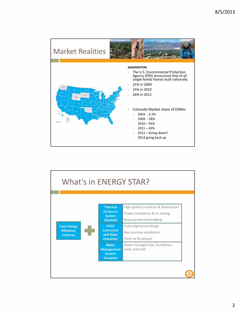
Market Realities
WASHINGTON
The U.S. Environmental Protection Agency (EPA) announced that of all single‐family homes built nationally
21% in 2009
25% in 2010
26% in 2011
Colorado Market share of ESNHs • 2004 ‐ 4.2%
• 2009 ‐ 28%
• 2010 – 45%
• 2011 – 43%
• 2012 – Going down?
• 2013 going back up
What’s in ENERGY STAR?
Core Energy Efficiency Features
Thermal Enclosure System Checklist
HVAC Contractor and Rater Checklists
Fully‐engineered design
Best practice installation
Fresh air & exhaust
Water Management
System Checklist
Water‐managed site, foundation, walls, and roof
High‐quality insulation & fenestration
Proper installation & air sealing
Reduced thermal bridging

8/5/2013
3
Use the correct checklist
Rev 7 Thermal Enclosure Checklist
ESv3 ‐ Knee wall air barrier
• Missing attic side air barrier
• R‐21 in all direction
8/5/2013
4
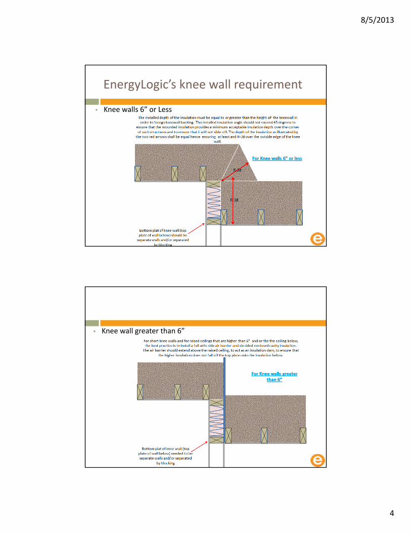
EnergyLogic’s knee wall requirement
Knee walls 6” or Less
Knee wall greater than 6”
8/5/2013
5
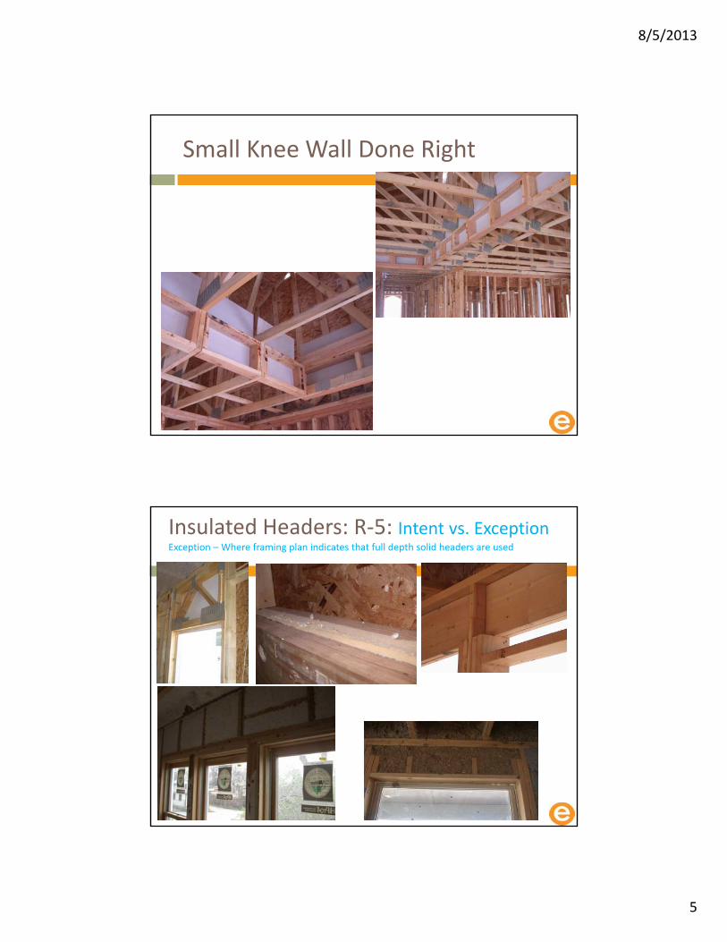
Small Knee Wall Done Right
Insulated Headers: R‐5: Intent vs. ExceptionException – Where framing plan indicates that full depth solid headers are used
8/5/2013
6
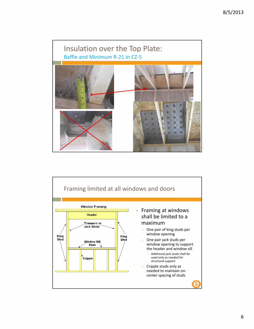
Insulation over the Top Plate:Baffle and Minimum R‐21 in CZ‐5
Framing limited at all windows and doors
Framing at windows shall be limited to a maximum • One pair of king studs per
window opening
• One pair jack studs per window opening to support the header and window sillo Additional jack studs shall be
used only as needed for structural support
• Cripple studs only as needed to maintain on‐center spacing of studs

8/5/2013
7
Footnote #21 (Exception)
“In Climate Zones 5 ‐ 8, a minimum stud spacing of 16 in. o.c. is permitted to be used with 2x6 framing if ≥ R‐20.0 wall insulation is installed”
Regardless, all vertical framing members shall either be on‐center or have an alternative structural purpose (e.g., framing members at the edge of pre‐fabricated panels) that is apparent to the Rater or documented in a framing plan…
The Rater need not evaluate the structural necessity of the framing plan to qualify the home.
However, all 2x6 framing with stud spacing of 16 in. o.c. in Climate Zones 5 ‐ 8 shall have ≥ R‐20.0 wall insulation installed regardless of any framing plan or alternative equivalent total UA calculation.”
HVAC Contractors Checklist

8/5/2013
8
HVAC System Quality Installation Rater Checklist ‐ page one
• Collect and Review o HVAC Contractor Checklist
o Ventilation System Design
o Full Load calculations
o AHRI Certificates
o Balancing report
HVAC System Contractor Checklist SectionFootnote #1
Footnote: #1
This Checklist is designed to :
• ASHRAE 62.2‐2010 and ANSI / ACCA’s 5 QI2007 protocol
• Improving the performance of HVAC equipment in new homes when compared to homes built to minimum code
However, these features alone cannot prevent all HVAC problems (e.g., those caused by a lack of maintenance by occupants)
Therefore, this Checklist is not a guarantee of proper ventilation, indoor air quality, or HVAC performance
This Checklist applies to:
• Ventilation systems
• Split air conditioners
• Unitary air conditioners,
• Air‐source / water‐source (i.e., geothermal) heat pumps up to 65,000 Btu / h and furnaces up to 225,000 Btu / h
All other equipment, including boilers, are exempt
If the ventilation system is the only applicable system installed in the home, then only Section 1 shall be completed
One Checklist shall be completed for each system and provided to the Rater.
The Checklist CANNOT be used to demonstrate compliance with the Indoor airPLUS specifications

8/5/2013
9
HVAC System Contractor Checklist SectionFootnote #2
Description of HVAC system location or area served e.g
• Whole house
• Upper level
• lower level
HVAC System Contractor Checklist Section Footnote #3
Check “Yes” if this system is to handle temporary occupant loads
Such a system may be required to accommodate a significant number of guests on a regular or sporadic basis and shall be handled by a supplemental cooling system • (e.g., a small, single‐package unit
or split‐coil unit) or by a system that can shift capacity from zone to zone (e.g., a variable volume system)
We should hardly ever see this
8/5/2013
10
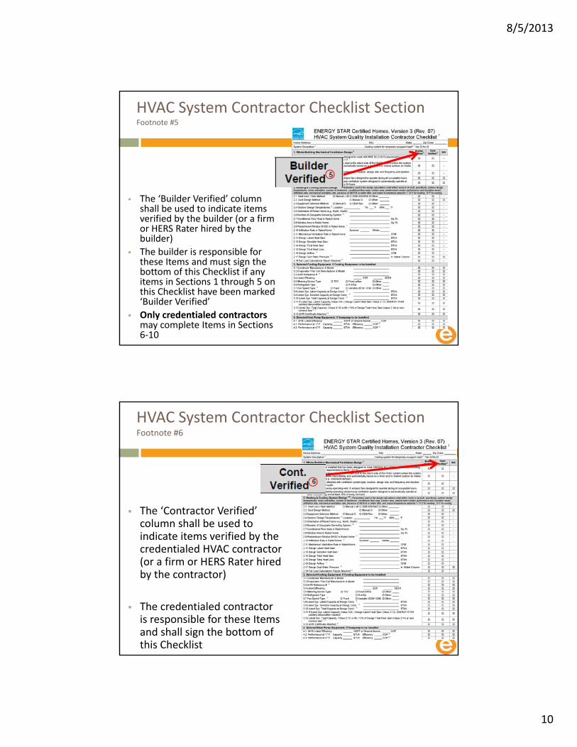
HVAC System Contractor Checklist Section Footnote #5
The ‘Builder Verified’ column shall be used to indicate items verified by the builder (or a firm or HERS Rater hired by the builder)
The builder is responsible for these Items and must sign the bottom of this Checklist if any items in Sections 1 through 5 on this Checklist have been marked ‘Builder Verified’
Only credentialed contractors may complete Items in Sections 6‐10
HVAC System Contractor Checklist Section Footnote #6
The ‘Contractor Verified’ column shall be used to indicate items verified by the credentialed HVAC contractor (or a firm or HERS Rater hired by the contractor)
The credentialed contractor is responsible for these Items and shall sign the bottom of this Checklist

8/5/2013
11
HVAC System Contractor Checklist Section #1
Footnote #4
The person responsible for the heating, cooling, and ventilation design shall be responsible for completing Sections 1 and 2 of this Checklist
HVAC Contractor Checklist 1. Whole‐Building Mechanical Ventilation
1.1Ventilation system installed has been designed to meet ASHRAE 62.2‐2010 requirements including, but not limited to, requirements in Items 1.2‐1.5
Footnote: #7• The system shall have at least one supply or exhaust fan with associated ducts and controls
• Local exhaust fans are allowed to be part of an exhaust ventilation system
• Outdoor air ducts connected to the return side of an air handler are allowed to be part of a supply ventilation system if manufacturer requirements for return air temperature are met

8/5/2013
12
Can a House Be Too Tight?
NO! Wrong question
Control air flow
In order to control the air
Real question ..........
Can houses be under‐ventilated?
YES!Build Tight and Ventilate Right
ASHRAE Standard 62.2 ‐ 2010
Standard for establishing consistent ventilation in a house
Both Whole House Controlled Mechanical Ventilation and Spot ventilation standard
This standard applies to spaces intended for human occupancy within single‐family houses and multifamily structures of three stories or fewer above grade, including manufactured and modular houses
American Society of Heating, Refrigerating, and Air‐Conditioning Engineers
Whole‐Building Mechanical Ventilation Design
8/5/2013
13
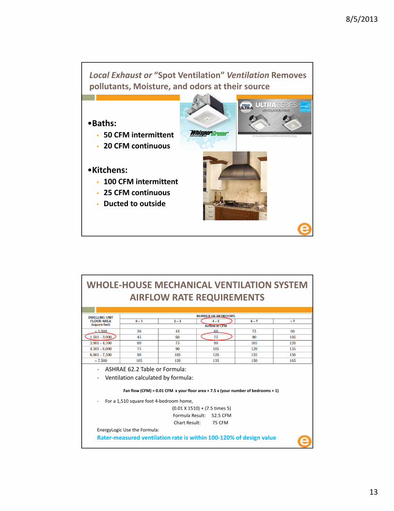
Local Exhaust or “Spot Ventilation” Ventilation Removes pollutants, Moisture, and odors at their source
•Baths:• 50 CFM intermittent
• 20 CFM continuous
•Kitchens:• 100 CFM intermittent
• 25 CFM continuous
• Ducted to outside
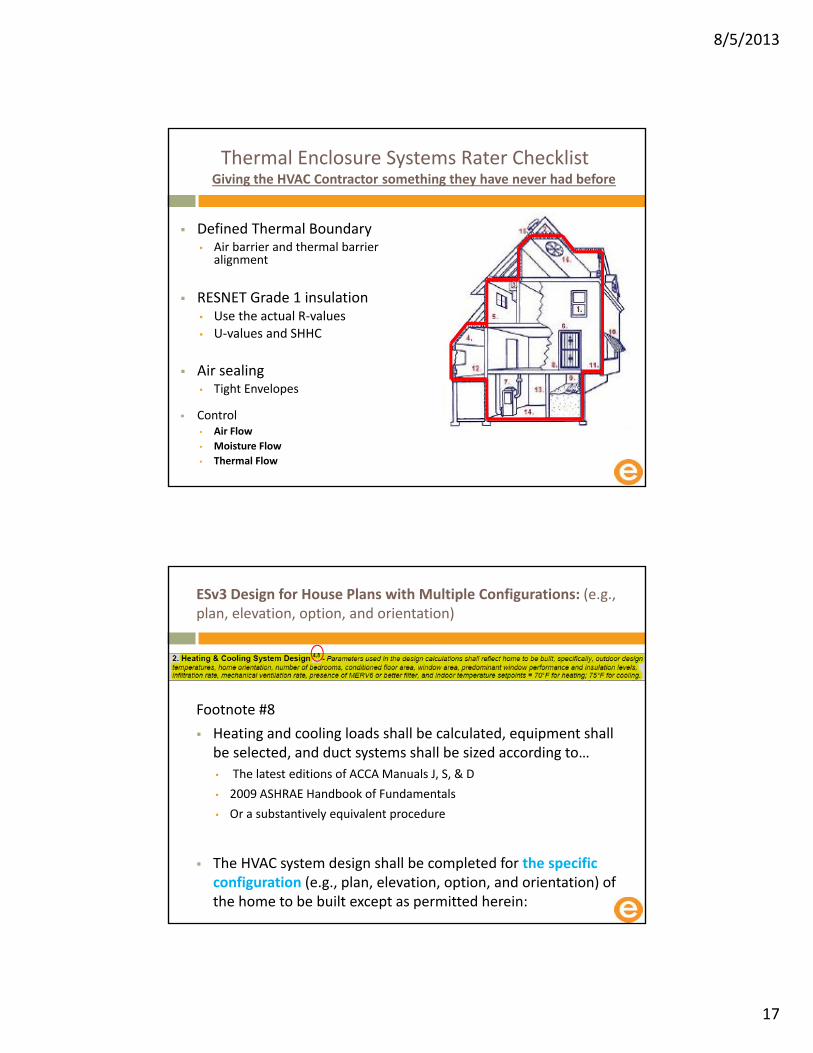
WHOLE‐HOUSE MECHANICAL VENTILATION SYSTEM AIRFLOW RATE REQUIREMENTS
ASHRAE 62.2 Table or Formula:
Ventilation calculated by formula:
Fan flow (CFM) = 0.01 CFM x your floor area + 7.5 x (your number of bedrooms + 1)
For a 1,510 square foot 4‐bedroom home,
(0.01 X 1510) + (7.5 times 5)
Formula Result: 52.5 CFM
Chart Result: 75 CFM
EnergyLogic Use the Formula:
Rater‐measured ventilation rate is within 100‐120% of design value

8/5/2013
14
Pick Your Ventilation Strategy Carefully to Maximize Performance
Three Strategies
Supply Ventilation (Furnace blower must be ECM/ICM)
Built Tight Ventilate Right
Exhaust Ventilation• Possible configuration with reversed
dampered designed opening to outside
Balanced Ventilation
There must be a control
Motion sensor
This controls the ventilation system
Recommend not turning off
Adjustable fan control highly recommended

8/5/2013
15
HVAC Contractor Checklist 1. Whole‐Building Mechanical Ventilation
Supply side ventilation:
1.2 Ventilation system does not utilize an intake duct to the return side of the HVAC system unless the system is designed to operate intermittently and automatically based on a timer and to restrict outdoor air intake when not in use (e.g., motorized damper)
Footnote: #16• If the whole‐house ventilation system utilizes
the HVAC air handler, then the fan speed type shall be ECM / ICM, variable speed, and run at a reduced speed during ventilation, or
• Include a controller (e.g., smart cycler) that reduces the ventilation run time by accounting for hours when HVAC system is heating or cooling the home
1.3 Documentation is attached with ventilation system type:
• Location
• design rate,
• Frequency and duration of each ventilation cycle
1.4 If present, continuously‐operating vent. & exhaust fans designed to operate during all occupiable hours
1.5 If present, intermittently‐operating whole‐house ventilation system designed to automatically operate at least once per day and at least 10% of every 24 hour period
HVAC Contractor Checklist 1. Whole‐Building Mechanical Ventilation

8/5/2013
16
Ventilation’s Impact on the HERS Index
The Home will not receive the energy benefit of building tighter than .35 NACH unless the house also has a controlled whole house mechanical ventilation • This is do to the RESNET and Energy Code Reference home which the Rated home is compared to
• Fan energy (watts) impacts the ability to fully take advantage of the trade offs for code and compliance for ESv3o Consider low watt draw ventilation strategies to lower the HERS Index Furnace blowers are not low watt draw
fans
HVAC System Contractor Checklist Section #2
2. Heating & Cooling System Design
Parameters used in the design calculations shall reflect home to be built – specifically:• Outdoor design temperatures
• Home orientation
• Number of bedrooms
• Conditioned floor area
• Window area
• Predominant window U‐value and SHGC
• Insulation R‐values
• Infiltration rate
• Mechanical ventilation rate
• Presence of MERV6 or better filter
• Indoor temperature set‐points o 70°F for heating; 75°F for cooling
8/5/2013
17
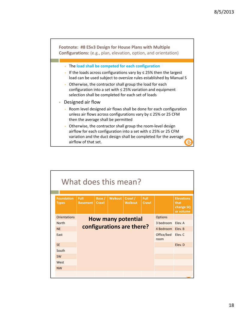
Thermal Enclosure Systems Rater ChecklistGiving the HVAC Contractor something they have never had before
Defined Thermal Boundary• Air barrier and thermal barrier
alignment
RESNET Grade 1 insulation• Use the actual R‐values• U‐values and SHHC
Air sealing• Tight Envelopes
Control • Air Flow
• Moisture Flow
• Thermal Flow
ESv3 Design for House Plans with Multiple Configurations: (e.g., plan, elevation, option, and orientation)
Footnote #8
Heating and cooling loads shall be calculated, equipment shall be selected, and duct systems shall be sized according to…
• The latest editions of ACCA Manuals J, S, & D
• 2009 ASHRAE Handbook of Fundamentals
• Or a substantively equivalent procedure
The HVAC system design shall be completed for the specific configuration (e.g., plan, elevation, option, and orientation) of the home to be built except as permitted herein:
8/5/2013
18
Footnote: #8 ESv3 Design for House Plans with Multiple Configurations: (e.g., plan, elevation, option, and orientation)
• The load shall be competed for each configuration
• If the loads across configurations vary by ≤ 25% then the largest load can be used subject to oversize rules established by Manual S
• Otherwise, the contractor shall group the load for each configuration into a set with ≤ 25% variation and equipment selection shall be completed for each set of loads
Designed air flow
• Room level designed air flows shall be done for each configuration unless air flows across configurations vary by ≤ 25% or 25 CFM then the average shall be permitted
• Otherwise, the contractor shall group the room‐level design airflow for each configuration into a set with ≤ 25% or 25 CFM variation and the duct design shall be completed for the average airflow of that set.
What does this mean?
Foundation Types
Full Basement
Base / Crawl
Walkout Crawl / Walkout
Full Crawl
Elevations thatchange SQ or volume
Orientations How many potential configurations are there?
Options
North 3 bedroom Elev. A
NE 4 Bedroom Elev. B
East Office/bedroom
Elev. C
SE Elev. D
South
SW
West
NW

8/5/2013
19
Batching in set that at ≤ 25%
North NE
East
SE South Sw
West NW
Start with Template Mover to Sit Specific ……………
North
NE
East
SE
South
SW
West
NW

8/5/2013
20
Site Specific Design
Rater Checklist
For each house plan with multiple configurations (e.g., orientations, elevations, options)
The Rater shall confirm that the parameters listed in Items 1.2.2 to 1.2.6 are aligned with the rated home
6
7
8
9
10
11
12
13
14
11 12 13 14 15
Rated SEER
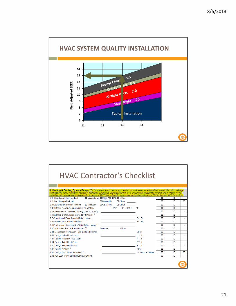
Typical Installation
Field Adjusted SEER
Courtesy of Advanced Energy Corp.
HVAC SYSTEM QUALITY INSTALLATIONChecklist is AC Centric
8/5/2013
21
11 12 13 14 15
Rated SEER
Typical Installation
Courtesy of Advanced Energy Corp.
Field Adjusted SEER
HVAC SYSTEM QUALITY INSTALLATION
HVAC Contractor’s Checklist

8/5/2013
22
Footnote: #9
If the design conditions are dictated by a code, then code requirements rule (We are getting better at recognizing this)
Otherwise, the default values shall be used
The values for the geographically closest location shall be selected or a justification provided for the selected location
Footnotes: #10
The number of occupants among all HVAC systems in the home must be equal to the number of bedrooms, as defined below, plus one (a Ventilation issue)
Occupants listed for systems serving temporary occupant loads, as described in Footnote 3, shall be permitted to exceed this limit (Discussed before)
A bedroom is defined by RESNET as a room or space 70 sq. ft. or greater size, with egress window and closet, used or intended to be used for sleeping
A "den", "library", or "home office" with a closet, egress window, and 70 sq. ft. or greater size or other similar rooms shall count as a bedroom, but living rooms and foyers shall not• An egress window, as defined in 2009 IRC section R310, shall refer to any operable window that
provides for a means of escape and access for rescue in the event of an emergency. The egress window shall:
• have a sill height of not more than 44 inches above the floor; AND
• have a minimum net clear opening of 5.7 sq. ft.; AND
• have a minimum net clear opening height of 24 in.; AND
• have a minimum net clear opening width of 20 in.; AND
• be operational from te inside of the room without the use of keys, tools or special knowledge
8/5/2013
23
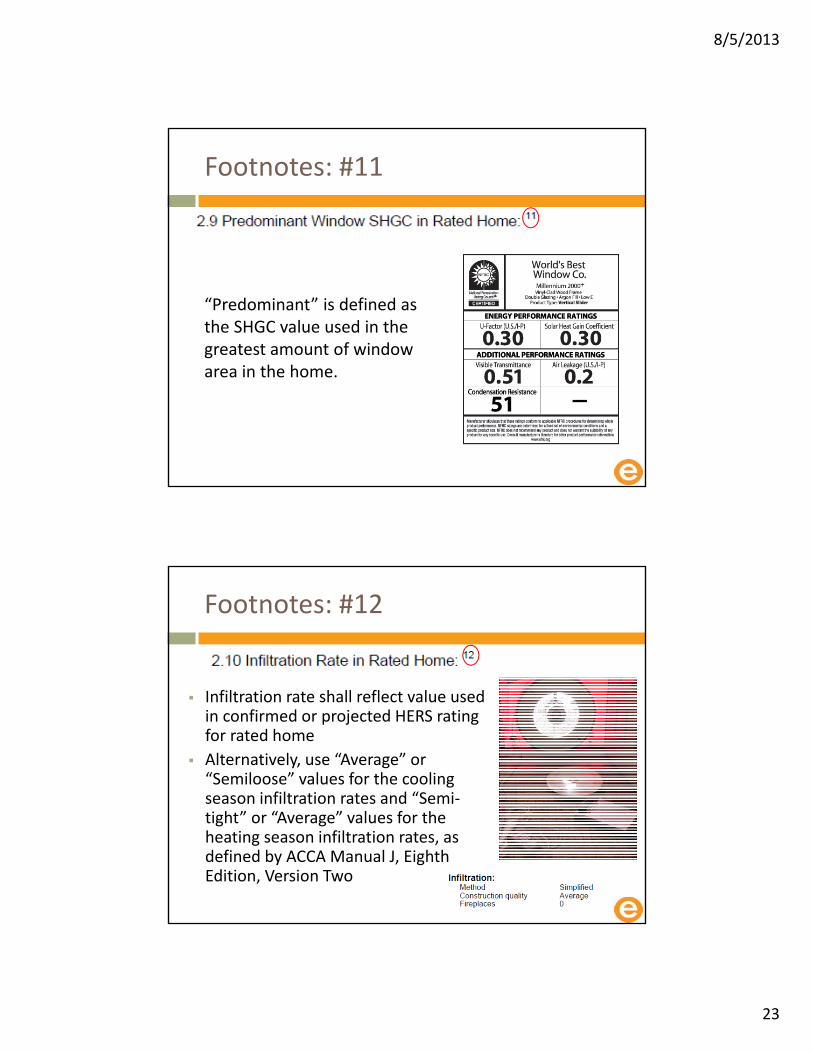
Footnotes: #11
“Predominant” is defined as the SHGC value used in the greatest amount of window area in the home.
Footnotes: #12
Infiltration rate shall reflect value used in confirmed or projected HERS rating for rated home
Alternatively, use “Average” or “Semiloose” values for the cooling season infiltration rates and “Semi‐tight” or “Average” values for the heating season infiltration rates, as defined by ACCA Manual J, Eighth Edition, Version Two

8/5/2013
24
Footnotes: #13
Design airflow is the design value(s) for the blower in CFM, as determined by using the manufacturer’s expanded performance data to select equipment, per ACCA Manual S procedures.
Footnotes: #14
Design duct static pressure shall account for the installation of a MERV 6 or higher filter.
8/5/2013
25
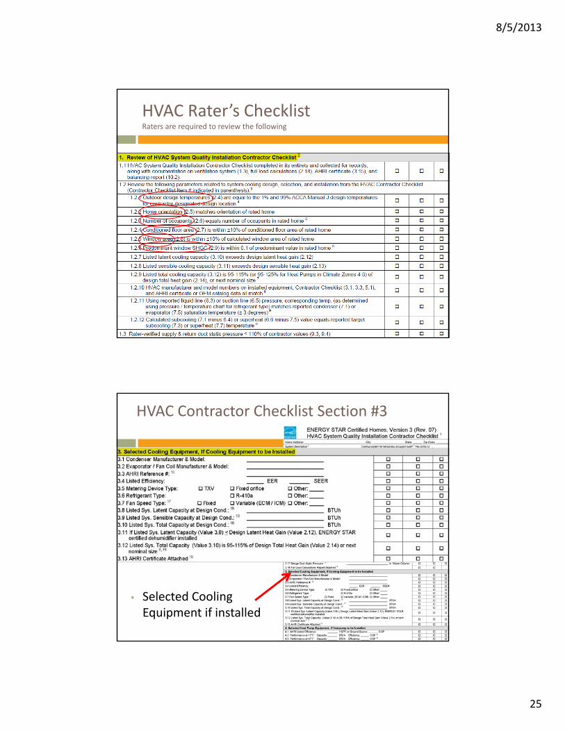
HVAC Rater’s ChecklistRaters are required to review the following
HVAC Contractor Checklist Section #3
• Selected Cooling Equipment if installed
8/5/2013
26
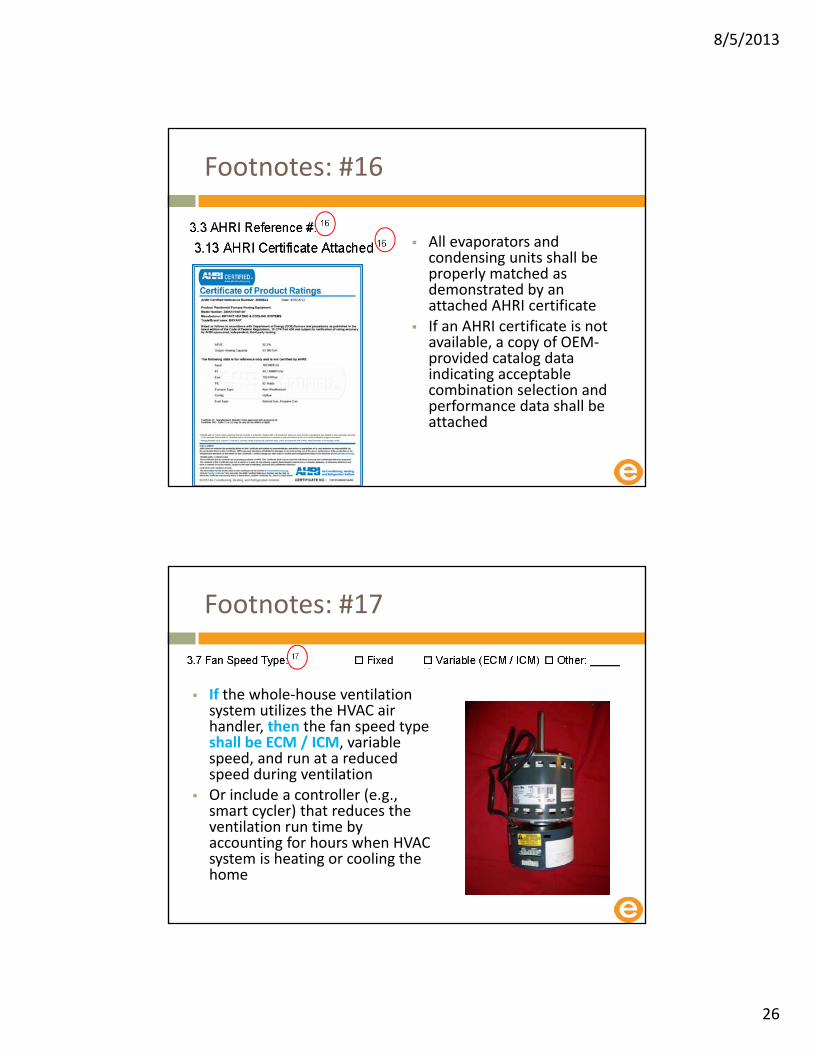
Footnotes: #16
All evaporators and condensing units shall be properly matched as demonstrated by an attached AHRI certificate
If an AHRI certificate is not available, a copy of OEM‐provided catalog data indicating acceptable combination selection and performance data shall be attached
Footnotes: #17
If the whole‐house ventilation system utilizes the HVAC air handler, then the fan speed type shall be ECM / ICM, variable speed, and run at a reduced speed during ventilation
Or include a controller (e.g., smart cycler) that reduces the ventilation run time by accounting for hours when HVAC system is heating or cooling the home
8/5/2013
27
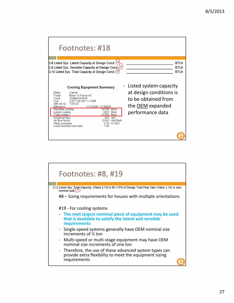
Footnotes: #18
Listed system capacity at design conditions is to be obtained from the OEM expanded performance data
Footnotes: #8, #19
#8 – Sizing requirements for houses with multiple orientations
#19 ‐ For cooling systems The next largest nominal piece of equipment may be used that is available to satisfy the latent and sensible requirements
Single‐speed systems generally have OEM nominal size increments of ½ ton
Multi‐speed or multi‐stage equipment may have OEM nominal size increments of one ton
Therefore, the use of these advanced system types can provide extra flexibility to meet the equipment sizing requirements

8/5/2013
28
HVAC System Contractor Checklist Section #4
HVAC Contractor Checklist Section #5

8/5/2013
29
Gas Furnace OEM SpecsTemperature Rise: Not required but good idea to measure!
Carrier 58MCB
Temp rise
30 to 60 F
Footnotes: #8,#21
#8 – Sizing requirements for houses with multiple orientations
#21 ‐ For warm air heating systems, the output capacity must be between 100% and 140% of calculated system load unless a larger size is dictated by the cooling equipment selection
8/5/2013
30
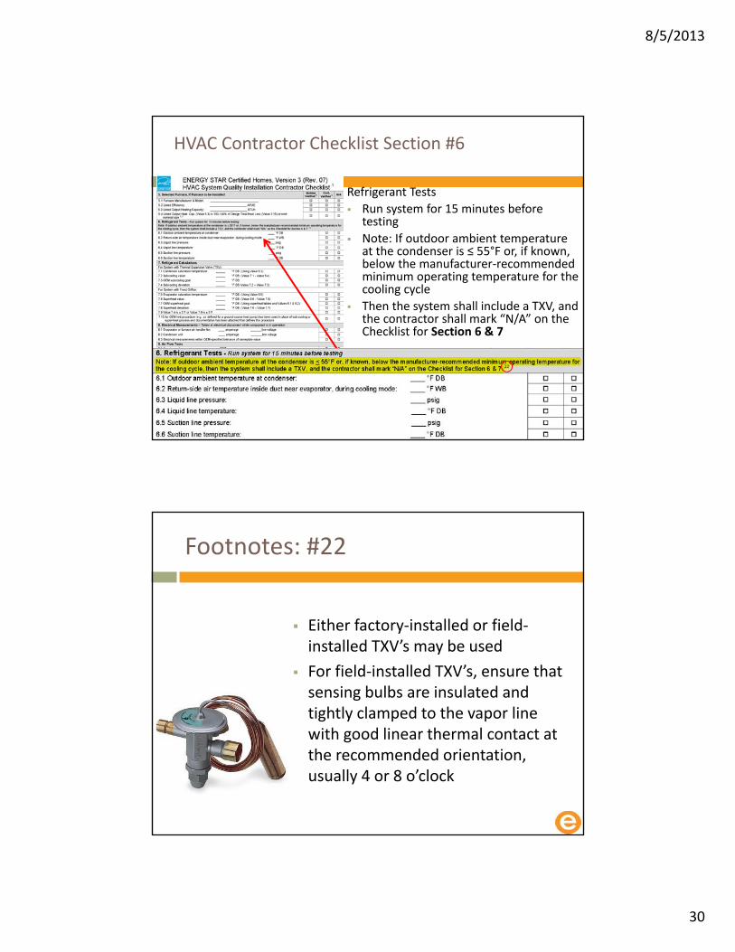
HVAC Contractor Checklist Section #6
Refrigerant Tests
Run system for 15 minutes before testing
Note: If outdoor ambient temperature at the condenser is ≤ 55°F or, if known, below the manufacturer‐recommended minimum operating temperature for the cooling cycle
Then the system shall include a TXV, and the contractor shall mark “N/A” on the Checklist for Section 6 & 7
Footnotes: #22
Either factory‐installed or field‐installed TXV’s may be used
For field‐installed TXV’s, ensure that sensing bulbs are insulated and tightly clamped to the vapor line with good linear thermal contact at the recommended orientation, usually 4 or 8 o’clock
8/5/2013
31
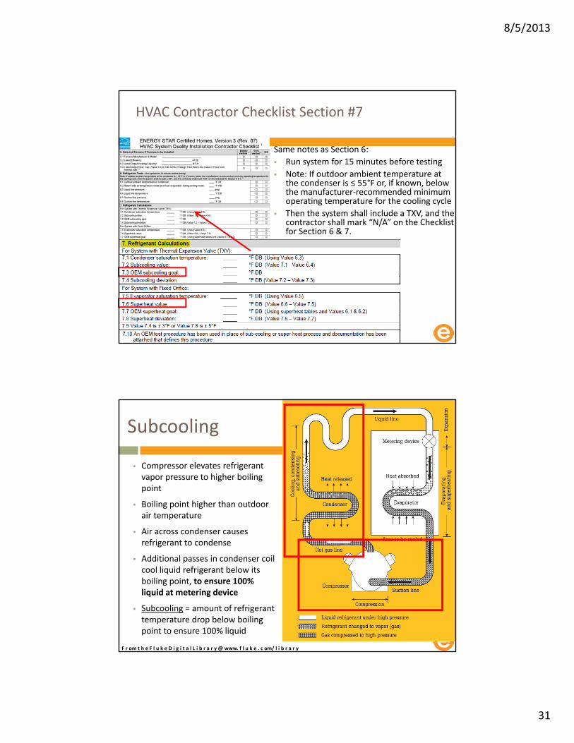
HVAC Contractor Checklist Section #7
Same notes as Section 6:
Run system for 15 minutes before testing
Note: If outdoor ambient temperature at the condenser is ≤ 55°F or, if known, below the manufacturer‐recommended minimum operating temperature for the cooling cycle
Then the system shall include a TXV, and the contractor shall mark “N/A” on the Checklist for Section 6 & 7.
Subcooling
Compressor elevates refrigerant vapor pressure to higher boiling point
Boiling point higher than outdoor air temperature
Air across condenser causes refrigerant to condense
Additional passes in condenser coil cool liquid refrigerant below its boiling point, to ensure 100% liquid at metering device
Subcooling = amount of refrigerant temperature drop below boiling point to ensure 100% liquid
F r om t h e F l u k e D i g i t a l L i b r a r y @ www. f l u k e . c om/ l i b r a r y

8/5/2013
32
Superheat
Metering device restricts refrigerant flow, drops refrigerant pressure to new, lower boiling point
Boiling point lower than indoor air temperature
Air across evaporator causes refrigerant to boil
Additional passes in evaporator coil warm gas above its boiling point ensures 100% gas at compressor
Superheat = amount of refrigerant temperature rise above boiling point to ensure 100% gas
F r om t h e F l u k e D i g i t a l L i b r a r y @ www. f l u k e . c om/ l i b r a r y
HVAC Contractor Checklist Section #8

8/5/2013
33
HVAC Contractor Checklist Section #9
Examples of return or supply duct static pressure measurement locations are:• Plenum, cabinet, trunk duct, as well as
front, back, left or right side
• Test hole locations shall be well marked and accessible
Static Pressure Measurements

8/5/2013
34
The measurement of the resistance to the flow of air in the duct system that the furnace fan has to work against
Everything external of the furnace cabinet
• Resistance to flow on the Supply side:o AC Coil
o Supply duct
o Register covers
• Resistance to flow on the Return side:o Filter
o Return duct
o return grills
ESP is the sum of the return pressure (‐) and the supply pressure (+) created by the blower
External Static Pressure (EPS)
ESP is measured using a manometer and is expressed in inches of water column (i.e., #” WC)
Return side readings are taken at the inlet to the furnace blower after the filter
Supply side readings are taken as the air is exiting the furnace cabinet before the evaporator coil
The sum of the two measurements are added together regardless of + or – signs to express the total ESP
External Static Pressure (EPS)

8/5/2013
35
External Static Pressure
A B
+188
Input Input
Ref Ref
ESP
Find targets in design submittal
Static pressures
Airflows through air handler
• Heating
• Cooling
Control strategy
Design Targets

8/5/2013
36
The only test done both by the Rater and the HVAC Contractor
Between the filter and the blower
Between the cabinet and the AC Coil
Test hole locations shall be well marked and accessible
9.6
Airflow volume at evaporator (Value 9.1), at fan design speed and full operating load, ± 15% of the airflow required per system design (Value 2.16) or within range recommended by OEM
Energy Star is no longer telling you how to test air flow
8/5/2013
37
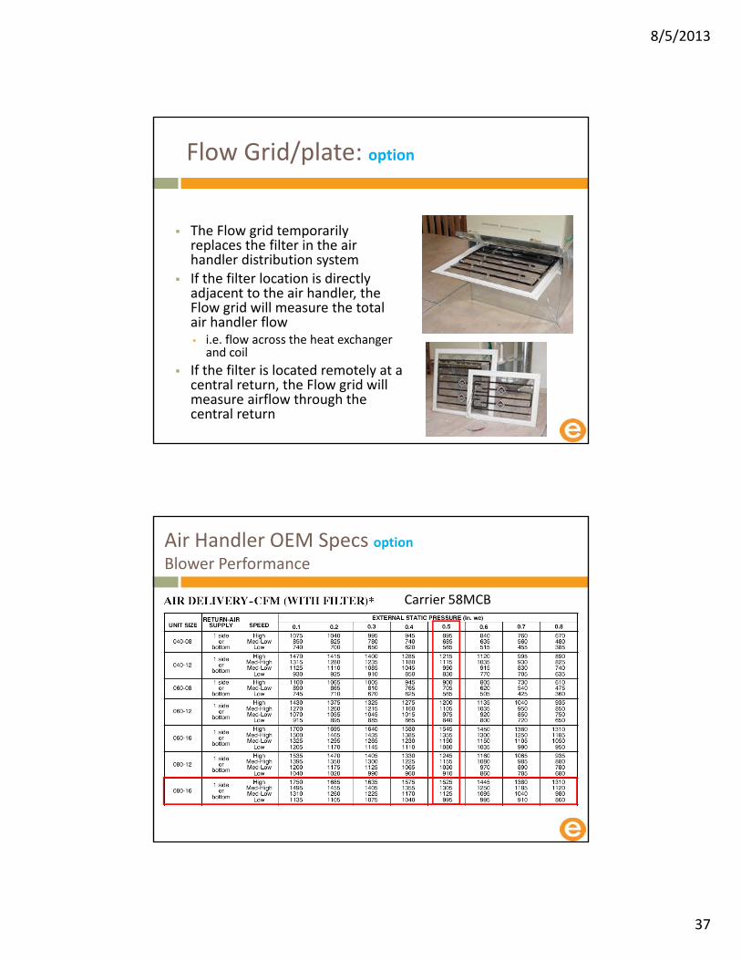
Flow Grid/plate: option
The Flow grid temporarily replaces the filter in the air handler distribution system
If the filter location is directly adjacent to the air handler, the Flow grid will measure the total air handler flow • i.e. flow across the heat exchanger and coil
If the filter is located remotely at a central return, the Flow grid will measure airflow through the central return
Air Handler OEM Specs optionBlower Performance
Carrier 58MCB
8/5/2013
38
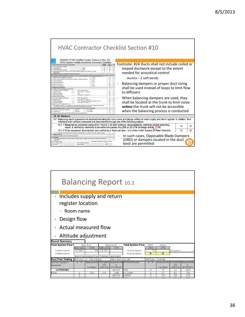
HVAC Contractor Checklist Section #10
Footnote: #24 Ducts shall not include coiled or looped ductwork except to the extent needed for acoustical control
• Aurora – 2 soft bends
Balancing dampers or proper duct sizing shall be used instead of loops to limit flow to diffusers
When balancing dampers are used, they shall be located at the trunk to limit noise unless the trunk will not be accessible when the balancing process is conducted
In such cases, Opposable Blade Dampers (OBD) or dampers located in the duct boot are permitted
c
Balancing Report 10.2
Includes supply and return register location
• Room name
Design flow
Actual measured flow
Altitude adjustment

8/5/2013
39
Flow hoods
HVAC Contractor Checklist Section #11

8/5/2013
40
HVAC Contractor Checklist Section #12
Footnote: 25
Condensate pan shall be made of corrosion‐resistant materials• Galvanized steel / plastic
Drain pan shall drain condensate to a conspicuous point of disposal to alert occupants in the event of a stoppage of the primary drainage system
And shall be equipped with a backflow prevention valve when drained to a shared drainage system, such as a storm water management system
c
Signature
New
A line has been added to the signature block For contractors to indicate their credentialing organization

8/5/2013
41
HVAC Rater’s Checklist
Checklist designed to align with ASHRAE 62.2 & ANSI/ACCA’s 5 QI 2007 Protocol
The Rater is only responsible for ensuring that the Contractor has completed the Contractor Checklist in its entirety and verifying the discrete objective parameters referenced in Section 1 of this Checklist
The Rater is not responsible for assessing the accuracy of the load calculations or field verifications included or for verifying the accuracy of every input on the Contractor Checklist
8/5/2013
42
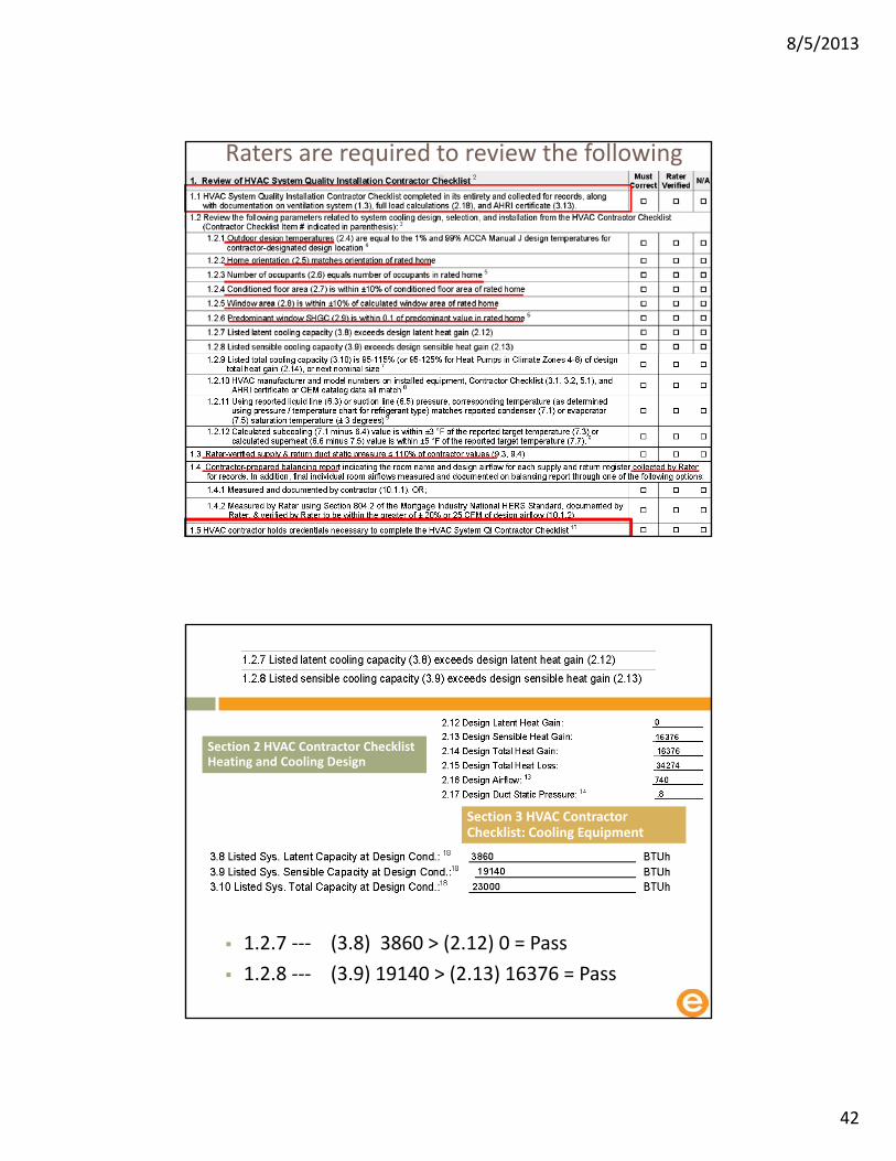
Raters are required to review the following
Section 2 HVAC Contractor Checklist Heating and Cooling Design
Section 3 HVAC Contractor Checklist: Cooling Equipment
1.2.7 ‐‐‐ (3.8) 3860 ˃ (2.12) 0 = Pass
1.2.8 ‐‐‐ (3.9) 19140 ˃ (2.13) 16376 = Pass

8/5/2013
43
1.2.9 Listed total cooling capacity (3.10) is 95‐115% (or 95‐125% for Heat Pumps in Climate Zones 4‐8) of design total heat gain (2.14), or next nominal size
Section 2 HVAC Contractor Checklist Heating and Cooling Design
Section 3 HVAC Contractor Checklist: Cooling Equipment
(3.10) 23000 (2.14) 16376
16376 x 1.15 = 18832.4 Next nominal size 24000
Footnote #7
For cooling systems, the next largest nominal piece of equipment may be used that is available to satisfy the latent and sensible requirements.
Single‐speed systems generally have OEM nominal size increments of ½ ton. Multi‐speed or multi‐stage equipment may have OEM nominal size increments of one ton. Therefore, the use of these advanced system types can provide extra flexibility to meet the equipment sizing requirements.

8/5/2013
44
Footnote #8
• In cases where the condenser unit is installed after the time of inspection:
• The HVAC manufacturer and model numbers on installed equipment can be documented through the use of photographs provided by the HVAC Contractor after installation is complete
1.2.11 Using reported liquid line (6.3) or suction line (6.5) pressure, corresponding temperature (as determined using pressure / temperature chart for refrigerant type) matches reported condenser (7.1) or evaporator (7.5) saturation temperature (± 3 degrees)
Section 6: Refrigerant Tests
Section 7; Refrigerant Calculation
(6.3) 350 (7.1) 107
8/5/2013
45
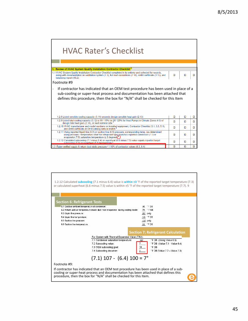
HVAC Rater’s Checklist
Footnote #9
• If contractor has indicated that an OEM test procedure has been used in place of a sub‐cooling or super‐heat process and documentation has been attached that defines this procedure, then the box for “N/A” shall be checked for this Item
1.2.12 Calculated subcooling (7.1 minus 6.4) value is within ±3 °F of the reported target temperature (7.3) or calculated superheat (6.6 minus 7.5) value is within ±5 °F of the reported target temperature (7.7). 9
Section 6: Refrigerant Tests
Section 7; Refrigerant Calculation
(7.1) 107 ‐ (6.4) 100 = 7°Footnote #9:
If contractor has indicated that an OEM test procedure has been used in place of a sub‐cooling or super‐heat process and documentation has been attached that defines this procedure, then the box for “N/A” shall be checked for this Item.

8/5/2013
46
HVAC System Quality Installation Rater Checklist
• Duct quality installation
• Duct insulation
• Duct leakage

8/5/2013
47
HVAC Rater’s Checklist Section #2
Footnote #11
Items 2.7 and 2.8 do not apply to ventilation ducts
However duct sealing does apply to ventilation and transfer ducts
HVAC Rater’s Checklist Section #2
Footnote #12
Kinks are to be avoided and are caused when ducts are bent across sharp corners such as framing members
Sharp bends are to be avoided and occur when the radius of the turn in the duct is less than one duct diameter

8/5/2013
48
Looking for better performance
HVAC Rater’s Checklist Section #2
Footnote #12
No coiled or looped ductwork except where needed for acoustical control
Balancing dampers or proper duct sizing used instead of loops to limit flow
Balancing dampers used shall be located at the trunk to limit noise unless the trunk will not be accessible when the balancing is conducted
In such cases, Opposable Blade Dampers (OBD) or dampers that are located in the duct boot are permitted

8/5/2013
49
8/5/2013
50
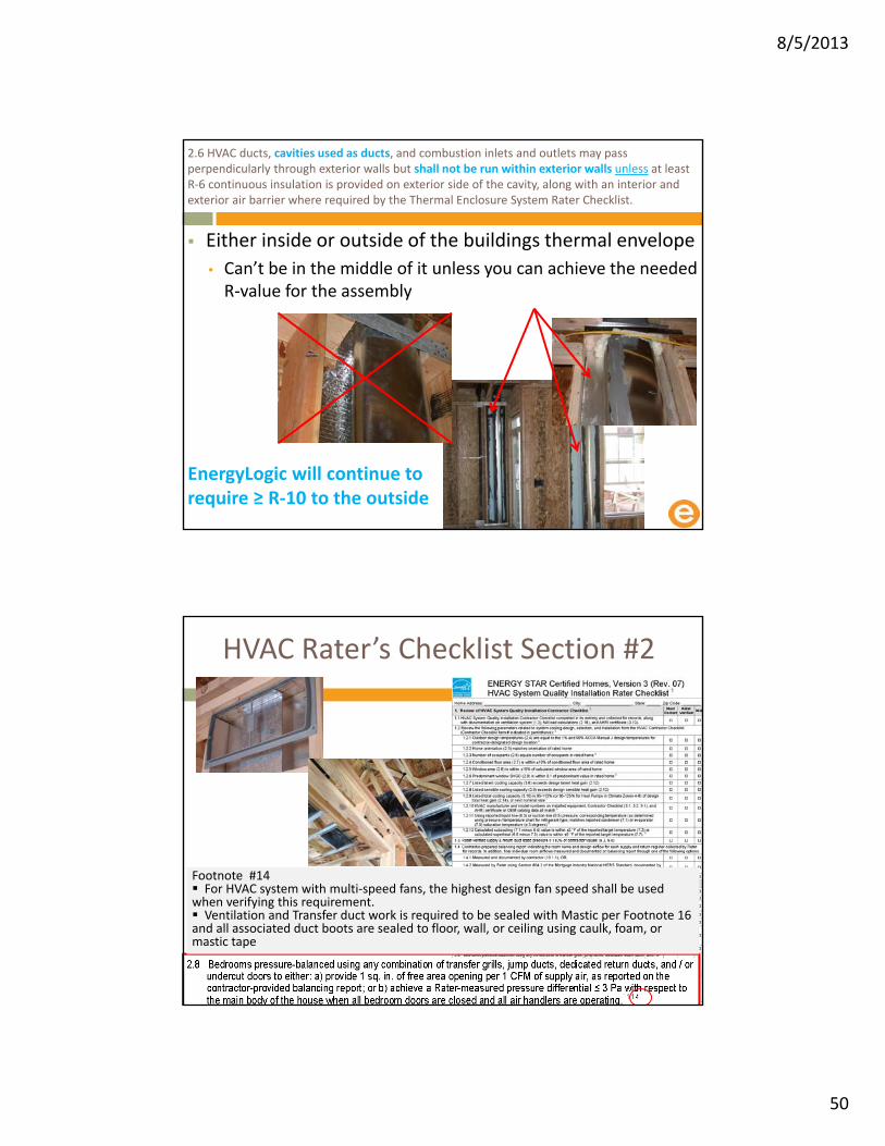
Either inside or outside of the buildings thermal envelope
• Can’t be in the middle of it unless you can achieve the needed R‐value for the assembly
2.6 HVAC ducts, cavities used as ducts, and combustion inlets and outlets may pass perpendicularly through exterior walls but shall not be run within exterior walls unless at least R‐6 continuous insulation is provided on exterior side of the cavity, along with an interior and exterior air barrier where required by the Thermal Enclosure System Rater Checklist.
EnergyLogic will continue to require ≥ R‐10 to the outside
HVAC Rater’s Checklist Section #2
Footnote #14 For HVAC system with multi‐speed fans, the highest design fan speed shall be used when verifying this requirement. Ventilation and Transfer duct work is required to be sealed with Mastic per Footnote 16and all associated duct boots are sealed to floor, wall, or ceiling using caulk, foam, or mastic tape

8/5/2013
51
HVAC Rater’s Checklist Section #3
Footnote #15
EPA recommends (not require) that all metal ductwork not covered by Section 3 (e.g., exhaust ducts, duct boots, ducts in conditioned space) also be insulated and that insulation be sealed to duct boots to prevent condensation.
HVAC Rater’s Checklist Section #4
Footnote #16
Duct leakage shall be determined and documented by a Rater using a RESNET‐approved testing protocol only after all components of the system have been installed (e.g., air handler and register grilles)
Leakage limits shall be assessed on a per‐system, rather than per‐home, basis

8/5/2013
52
Total Duct leakage target moving to 4 CFM/100sqft Consistent with the 2012 IECC target
Tested at rough
• 4≤ CFM 25 per 100 sqft of conditioned floor area
• 2000 sqft house
• 8 CFM = 160 CFM@25 max
• 6CFM = 120 CFM@25 max
• 4 CFM = 80 CFM@25 max
Footnote 17
Cabinets (e.g., kitchen, bath, multimedia) or ductwork that connect duct boots to toe‐kick registers are not required to be in place during the ‘rough‐in’ test
Phased in Target
• Home permitted in 2013 rough‐in leakage target is ≤ 6 CFM@25 per 100 sq. ft. of CFA with air handler and all ductwork & duct boots installed
• For Home permitted in 2014 target is 4 CFM@25

8/5/2013
53
Rater must verify that HVAC supply and return register boots are sealed to subfloor and drywall throughout the house
Total Duct LeakageInside and outside the building envelope
A B
25+
1. Block off supply and return openings2. Block off controlled mechanical ventilation3. Set up Duct blaster on return side4. Insert test tape on supply side and hose to fan5. Turn on fan and read +25 at test tap6. Walk house check tape and blocking7. Check gauge is still at +258. Read flow at duct blaster
Input Input
Ref Ref
Duct Blaster
Supply sideReturn side
Blower cabinet
794

8/5/2013
54
Total Duct leakage at Final
Footnote 18
• Registers atop carpets are permitted to be removed and the face of the duct boot temporarily sealed during testing.
• In such cases, the Rater shall visually verify that the boot has been durably sealed to the subfloor (e.g., using duct mastic or caulk) to prevent leakage during normal operation.
Getting to 4 CFM
We are seeing it now – Consistency is the issue
Seal every seam

8/5/2013
55
Duct Leakage to Outside
≤ 4 CFM 25 per 100 sqft of conditioned floor area
2000 sqft house ≤ 80 CFM 25 total
+25 Pa
Duct Leakage to Outside
Use blower door to pressurize house and ducts to +25 Pa wrt outside
Duct leakage to indoors eliminated
+25
+25

8/5/2013
56
Turn on duct tester fan Goal: Match the CFM of the blower door air leaving the ducts
+25 Pa
Duct Leakage to Outside
+25
+25
A B
‐0.0
Adjust duct tester to 0.0 Pa ductwork wrt house Measure duct tester airflow (CFM) Report as 103 CFM25 duct leakage to outdoors
Ref Ref
Input Input
103
+25 Pa
Duct Leakage to Outside
+25 Pa
+25
+25
‐0.9
8/5/2013
57
HVAC Rater’s Checklist Section #4
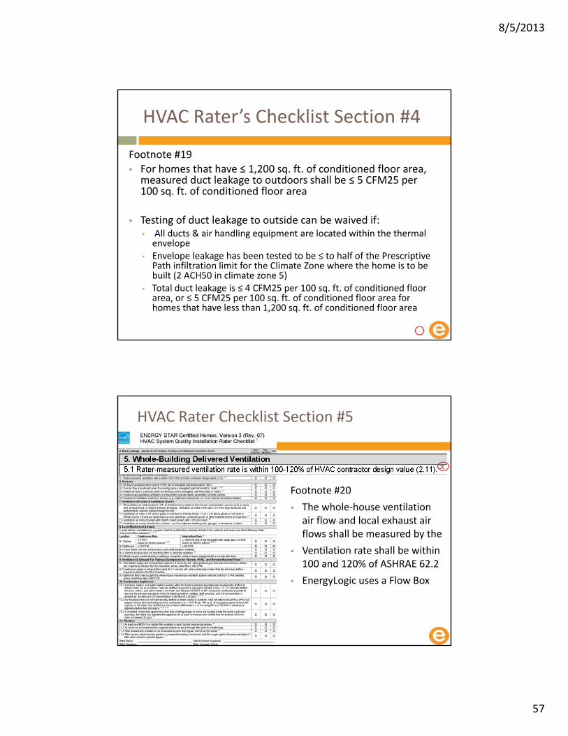
Footnote #19 For homes that have ≤ 1,200 sq. ft. of conditioned floor area, measured duct leakage to outdoors shall be ≤ 5 CFM25 per 100 sq. ft. of conditioned floor area
Testing of duct leakage to outside can be waived if:• All ducts & air handling equipment are located within the thermal envelope
• Envelope leakage has been tested to be ≤ to half of the Prescriptive Path infiltration limit for the Climate Zone where the home is to be built (2 ACH50 in climate zone 5)
• Total duct leakage is ≤ 4 CFM25 per 100 sq. ft. of conditioned floor area, or ≤ 5 CFM25 per 100 sq. ft. of conditioned floor area for homes that have less than 1,200 sq. ft. of conditioned floor area
HVAC Rater Checklist Section #5
Footnote #20
The whole‐house ventilation air flow and local exhaust air flows shall be measured by the
Ventilation rate shall be within 100 and 120% of ASHRAE 62.2
EnergyLogic uses a Flow Box

8/5/2013
58
HVAC Rater Checklist Section #6
Footnote #21
In cases where the condenser unit is installed after the time of inspection by the Rater, the Rater is exempt from verifying Item 6.2 when the condenser is for an AC unit and also Item 6.3 when the condenser is for a heat pump unit
HVAC Rater Checklist Section #6
Footnote #22
To prevent potential equipment damage, the Rater shall not conduct this test if the outdoor temperature is ≤ 55°F or, if known, below the manufacturer‐recommended minimum operating temperature for the cooling cycle
When this occurs, the Rater shall mark ‘N/A’ on the Checklist for this item
8/5/2013
59
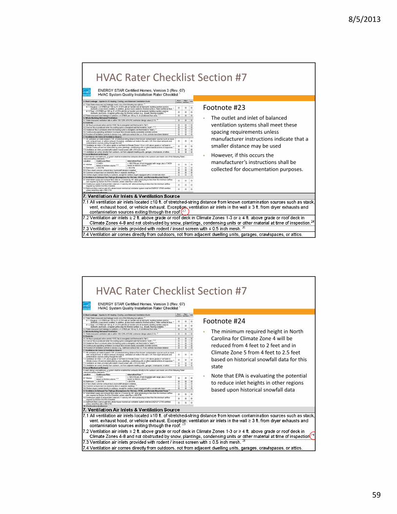
HVAC Rater Checklist Section #7
Footnote #23
The outlet and inlet of balanced ventilation systems shall meet these spacing requirements unless manufacturer instructions indicate that a smaller distance may be used
However, if this occurs the manufacturer’s instructions shall be collected for documentation purposes.
HVAC Rater Checklist Section #7
Footnote #24
The minimum required height in North Carolina for Climate Zone 4 will be reduced from 4 feet to 2 feet and in Climate Zone 5 from 4 feet to 2.5 feet based on historical snowfall data for this state
Note that EPA is evaluating the potential to reduce inlet heights in other regions based upon historical snowfall data
8/5/2013
60
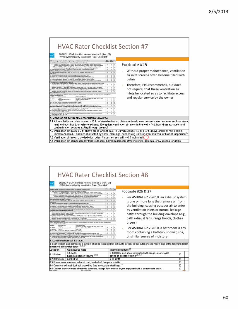
HVAC Rater Checklist Section #7
Footnote #25
Without proper maintenance, ventilation air inlet screens often become filled with debris
Therefore, EPA recommends, but does not require, that these ventilation air inlets be located so as to facilitate access and regular service by the owner
HVAC Rater Checklist Section #8
Footnote #26 & 27
Per ASHRAE 62.2‐2010, an exhaust system is one or more fans that remove air from the building, causing outdoor air to enter by ventilation inlets or normal leakage paths through the building envelope (e.g., bath exhaust fans, range hoods, clothes dryers)
Per ASHRAE 62.2‐2010, a bathroom is any room containing a bathtub, shower, spa, or similar source of moisture

8/5/2013
61
HVAC Rater Checklist Section #8
Footnote #28
An intermittent mechanical exhaust system shall be designed to operate as needed by the occupant
Control devices shall not impede occupant control in intermittent systems
HVAC Rater Checklist Section #8
For homes permitted through 01/01/2014:
Homes are permitted to be certified without enforcement of this Item to provide partners with additional time to integrate this feature into their homes.

8/5/2013
62
HVAC Rater Checklist Section #8
For homes permitted on or after 01/01/2014:
Homes shall meet this Item.
Alternatively, the prescriptive duct sizing requirements in Table 5.3 of ASHRAE 62.2‐2010 are permitted to be used for kitchen exhaust fans based upon the rated airflow of the fan at 0.25 IWC.
If the rated airflow is unknown, ≥ 6 in. smooth duct shall be used, with a rectangular to round duct transition as needed.
Guidance to assist partners with these alternatives is available at www.energystar.gov/newhomesresources.
As an alternative to Item 8.1, homes that are PHIUS+ certified are permitted to use a continuous kitchen exhaust rate of 25 CFM per 2009 IRC Table M1507.3.
HVAC Rater Checklist Section #8
Footnote #31
All intermittent kitchen exhaust fans must be capable of exhausting at least 100 CFM.
In addition, if the fan is not part of a vented range hood or appliance‐range hood combination (i.e., if the fan is not integrated with the range), then it must also be capable of exhausting ≥ 5 ACH, based on the kitchen volume.
8/5/2013
63
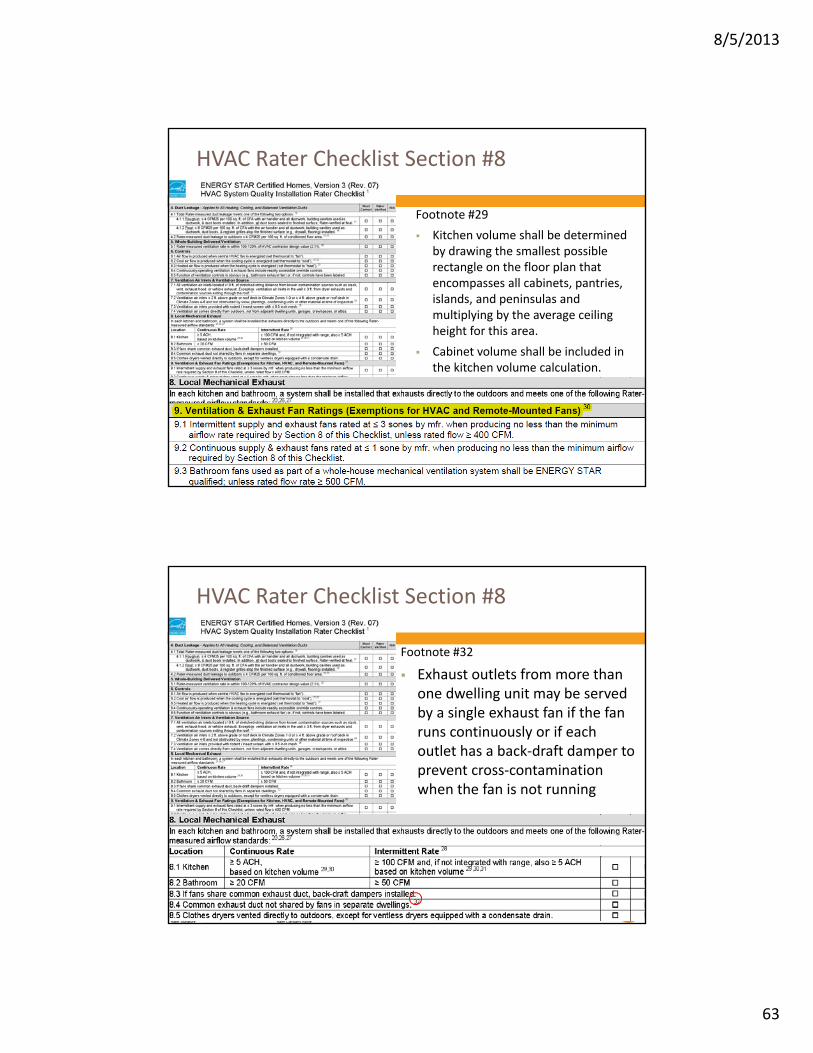
HVAC Rater Checklist Section #8
Footnote #29
Kitchen volume shall be determined by drawing the smallest possible rectangle on the floor plan that encompasses all cabinets, pantries, islands, and peninsulas and multiplying by the average ceiling height for this area.
Cabinet volume shall be included in the kitchen volume calculation.
HVAC Rater Checklist Section #8
Footnote #32
Exhaust outlets from more than one dwelling unit may be served by a single exhaust fan if the fan runs continuously or if each outlet has a back‐draft damper to prevent cross‐contamination when the fan is not running

8/5/2013
64
HVAC Rater Checklist Section #9
Footnote #33
Fans exempted from this requirement include HVAC air handlers and remote‐mounted fans
To be considered for this exemption, a remote‐mounted fan must be mounted outside the habitable spaces, bathrooms, toilets, and hallways and there shall be ≥ 4 ft. ductwork between the fan and intake grill
Per ASHRAE 62.2‐2010, habitable spaces are intended for continual human occupancy; such space generally includes areas used for living, sleeping, dining, and cooking but does not generally include bathrooms, toilets, hallways, storage areas, closets, or utility rooms
HVAC Rater Checklist Section #10
Footnote #34
Per the 2009 International Mechanical Code, a direct‐vent appliance is one that is constructed and installed so that all air for combustion is derived from the outdoor atmosphere and all flue gases are discharged to the outside atmosphere
A mechanical draft system is a venting system designed to remove flue or vent gases by mechanical means consisting of an induced draft portion under non‐positive static pressure or a forced draft portion under positive static pressure
A natural draft system is a venting system designed to remove flue or vent gases under non‐positive static vent pressure entirely by natural draft

8/5/2013
65
HVAC Rater Checklist Section #11
Footnote #40
Per ASHRAE 62.2‐2010, ducted mechanical systems are those that supply air to an occupiable space through ductwork exceeding 10 ft. in length and through a thermal conditioning component, except for evaporative coolers
Systems that do not meet this definition are exempt from this requirement
Also, mini‐split systems typically do not have MERV‐rated filters available for use and are, therefore, exempted under this version of the guidelines
HVAC Rater Checklist Section #11
Footnote #41
HVAC filters located in the attic shall be considered accessible to the owner if drop‐down stairs provide access to attic and a permanently installed walkway has been provided between the attic access location and the filter
0

8/5/2013
66
HVAC Rater Checklist Section #11
Footnote #42
The filter media box (i.e., the component in the HVAC system that houses the filter) may be either site‐fabricated by the installer or pre‐fabricated by the manufacturer to meet this requirement
These requirements only apply when the filter is installed in a filter media box located in the HVAC system, not when the filter is installed flush with the return grill
0
Get Started Today!
@energystarhomes facebook.com/energystar
Join a credentialing programwww.energystar.gov/newhomesHVAC
Find builder partnerswww.energystar.gov/partnerlocator
Read the technical guidelineswww.energystar.gov/newhomesguidelines
8/5/2013
67
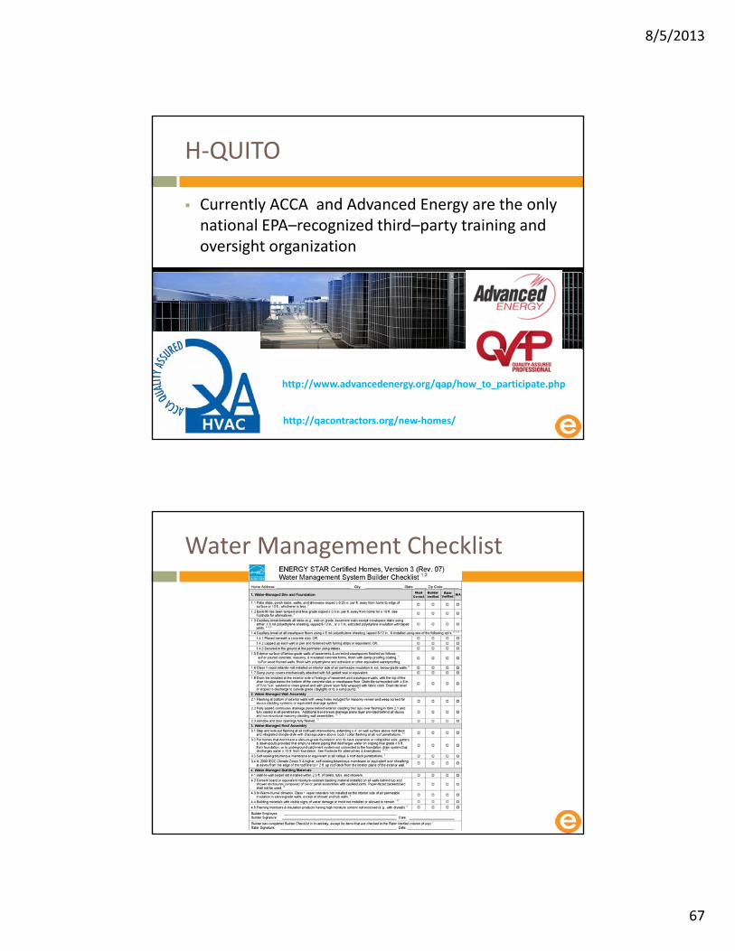
H‐QUITO
Currently ACCA and Advanced Energy are the only national EPA–recognized third–party training and oversight organization
http://www.advancedenergy.org/qap/how_to_participate.php
http://qacontractors.org/new‐homes/
Water Management Checklist

8/5/2013
68
Water Management Checklist
We have asked Energy Star for clarification but have not heard back yet.
Water Management Checklist
Prior allowances to complete certain ES requirements in lieu of IAP requirements, & vice versa, have been deleted and unintentional discrepancies have been aligned.
This will ease compliance for homes that earn both labels.

8/5/2013
69
Indoor Air Plus Now completely a stand alone program
Moisture control
• Water Managed site & foundation
o Drainage, Capillary break, damp proofed, Etc.
• Water managed Wall assemblies
o Drainage plane, flashing details
• Water managed Roof assemblies
o Gutters and flashing
• Interior water management
o Moisture resistant materials
Radon control• Radon resistant features including at least a
passive radon system
Pest Barriers
• Minimize pathway for pests
HVAC Systems
• Heating & Cooling equipmento Sizing and design
• Ventilationo ASHREA 62.2
• Air cleaning and filtration
• Dehumidification
Combustion pollutant control
• Combustion source Controlso Sealed or power vented equipment
• Attached garageso Insolated
Low emission materials
• Engineered woods, Paints, Carpets
Home commissioning
• Duct testing, Pressure balancing, Flows, Etc.
Water Management Checklist
Difficult items on the checklist:
Wall‐to‐wall carpet not installed within 2.5 ft. of toilets, tubs, and showers.
Class 1 vapor retarder not installed on interior side of air permeable insulation in ext. below‐grade walls

8/5/2013
70
Energy Star V3 HVAC Checklists
Thank you!
www.nrglogic.com
720‐838‐0677
Upside down house Szymbark Poland