the official generative machining ascii cldata output...
TRANSCRIPT
The OfficialGenerative Machining
ASCII CLDATA Output SpecificationAugust 9, 2000Version 8.1.1
MODE/MILLMULTAX/ONGOHOMELOADTL/0, IN, 1, LENGTH, 0.000000, OSETNO, 0CUTTER/6.000000LINTOL/0.050000SPINDL/1910.000, RPM, CLWRAPIDGOTO/308.427225, -75.000001, 143.449146, 0.819150, 0.000000, 0.573580RAPIDGOTO/308.427225, -75.000001, 86.310234, 0.819150, 0.000000, 0.573580COOLNT/FLOODCYCLE/DRILL, 14.802582, MMPR, 0.127000, 10.000000, RAPTO, 5.000000GOTO/267.453123, -75.000001, 57.619609, 0.819150, 0.000000, 0.573580CYCLE/OFFRAPIDGOTO/308.427225, -75.000001, 86.310234, 0.819150, 0.000000, 0.573580RAPIDGOTO/308.427225, -75.000001, 143.449146, 0.819150, 0.000000, 0.573580RAPIDGOTO/318.379825, -112.505078, 143.449146, 0.819152, 0.000000, 0.573576RAPIDGOTO/318.379825, -112.505078, 72.095689, 0.819152, 0.000000, 0.573576CYCLE/DRILL, 14.802582, MMPR, 0.127000, 10.000000, RAPTO, 5.000000GOTO/277.405962, -112.505078, 43.405482, 0.819152, 0.000000, 0.573576CYCLE/OFFRAPIDGOTO/318.379825, -112.505078, 72.095689, 0.819152, 0.000000, 0.573576RAPIDGOTO/318.379825, -112.505078, 143.449146, 0.819152, 0.000000, 0.573576RAPIDGOTO/300.503903, -57.868905, 143.449146, 0.819152, 0.000000, 0.573576RAPIDGOTO/300.503903, -57.868905, 97.625152, 0.819152, 0.000000, 0.573576CYCLE/DRILL, 14.802582, MMPR, 0.127000, 10.000000, RAPTO, 5.000000GOTO/259.530040, -57.868905, 68.934944, 0.819152, 0.000000, 0.573576CYCLE/OFFCOOLNT/OFFRAPIDGOTO/300.503903, -57.868905, 97.625152, 0.819152, 0.000000, 0.573576RAPIDGOTO/300.503903, -57.868905, 143.449146, 0.819152, 0.000000, 0.573576GOHOMEENDFINI

Generative Machining ASCII CLDATA Output SpecificationAugust 09, 2000
Version 8.1
1. ASCII CLDATA VocabularyThis section specifies the format of the Generative Machining ASCII cldata output. Thisoutput is based on the ISO-4343 1978 standard. Parameters enclosed in brackets [ ,aaa |,bbb | ,ccc ] indicate a choice of parameters. The vertical bar | divides the choices.Parameters enclosed in braces {xxx, yyy, zzz} indicate optional parameters. Optionalparameters with choices are enclosed in braces and brackets {[ ,xxx | ,yyy | ,zzz ]}. The ~symbol preceding items in brackets or braces indicates that the item can be repeated one ormore times. Parameters specified in upper case are used literally in the format. Valid entriesfor all other parameters are detailed following the command format.
1.1. Motion Definition and Control Commands
1.1.1. GOTOThis statement produces a linear motion at the present feedrate (given by FEDRAT).
GOTO/ x, y, z {,i, j, k}
Variable Type Descriptionx Real X Axis positiony Real Y Axis positionz Real Z Axis positioni Real X Axis component of tool axis vectorj Real Y Axis component of tool axis vectork Real Z Axis component of tool axis vector
Usage
The IJK values are only output in MULTAX mode, which must be declared by theMULTAX/ON statement.
1.1.2. MOVARCThe MOVARC statement defines a circular move.
MOVARC/ x1, y1 ,z1 ,i ,j ,k ,r, ANGLE, aGOTO/ x2, y2, z2 {, i2, j2,k2 }
Variable Type Descriptionx1 Real X Axis position of the arc centery1 Real Y Axis position of the arc centerz1 Real Z Axis position of the arc centeri Real X Axis component of arc (circle) axis vectorj Real Y Axis component of arc (circle) axis vectork Real Z Axis component of arc (circle) axis vectorr Real Radius of the arca Real subtended (included) angle of the arcx2,y2,z2 Real arc end point
Usage
Generative Machining ASCII CLDATA Output SpecificationAugust 09, 2000
Version 8.1
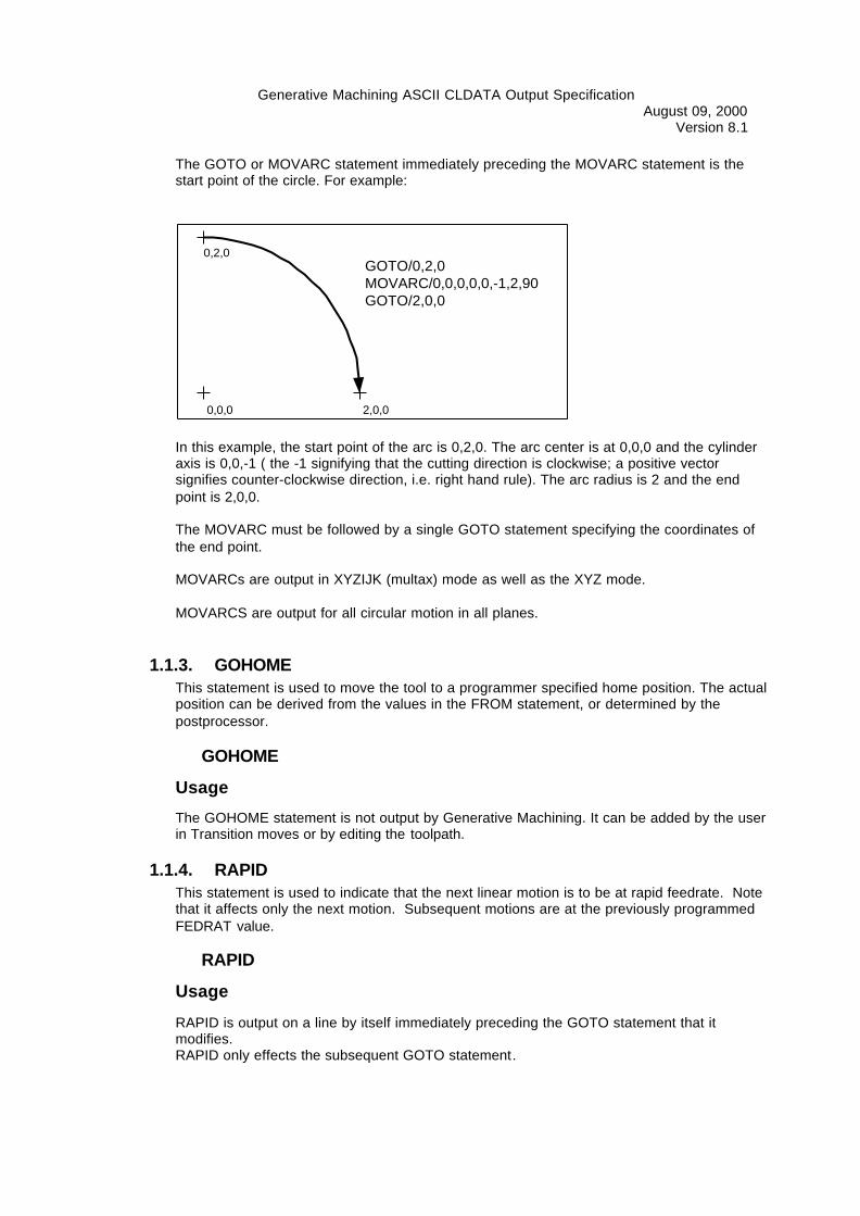
The GOTO or MOVARC statement immediately preceding the MOVARC statement is thestart point of the circle. For example:
0,0,0
0,2,0
2,0,0
GOTO/0,2,0MOVARC/0,0,0,0,0,-1,2,90GOTO/2,0,0
In this example, the start point of the arc is 0,2,0. The arc center is at 0,0,0 and the cylinderaxis is 0,0,-1 ( the -1 signifying that the cutting direction is clockwise; a positive vectorsignifies counter-clockwise direction, i.e. right hand rule). The arc radius is 2 and the endpoint is 2,0,0.
The MOVARC must be followed by a single GOTO statement specifying the coordinates ofthe end point.
MOVARCs are output in XYZIJK (multax) mode as well as the XYZ mode.
MOVARCS are output for all circular motion in all planes.
1.1.3. GOHOMEThis statement is used to move the tool to a programmer specified home position. The actualposition can be derived from the values in the FROM statement, or determined by thepostprocessor.
GOHOME
Usage
The GOHOME statement is not output by Generative Machining. It can be added by the userin Transition moves or by editing the toolpath.
1.1.4. RAPIDThis statement is used to indicate that the next linear motion is to be at rapid feedrate. Notethat it affects only the next motion. Subsequent motions are at the previously programmedFEDRAT value.
RAPID
Usage
RAPID is output on a line by itself immediately preceding the GOTO statement that itmodifies.RAPID only effects the subsequent GOTO statement.

Generative Machining ASCII CLDATA Output SpecificationAugust 09, 2000
Version 8.1Generative Machining will always output the RAPID statement immediately before theeffected GOTO statement that it.
1.1.5. FROMThis statement specifies the "home" position for the tool.
FROM/ x, y, z, {i, j, k}
Variable Type Descriptionx Real X Axis positiony Real Y Axis positionz Real Z Axis positioni Real X Axis component of tool axis vectorj Real Y Axis component of tool axis vectork Real Z Axis component of tool axis vector
Usage
The FROM statement is only output when there is a machine defined (which only affectsmilling programs. Turning programs must always have a machine defined).
In milling programs, the FROM statement is output once at the beginning of the programbefore the first tool change. The XYZ coordinates in the FROM statement are thosespecified by the user on the machine form for the HOME POINT.
In turning programs, a FROM statement is output immediately after the first HEAD statementfor each turret (presently a maximum of two). The XYZ coordinates in the FROM statementsare those specified by the user on the machine form for the HOME POINT for the TURRETbeing used.
1.1.6. MULTAXThis statement indicates that output in the form of XYZIJK will follow. MULTAX/ ON willprecede any GOTO or FROM statement which contains i, j, k values. MULTAX statementswill be re-issued after each tool change.
MULTAX/ [ON, OFF]
1.1.7. CUTTER
1.1.7.1. Milling Format
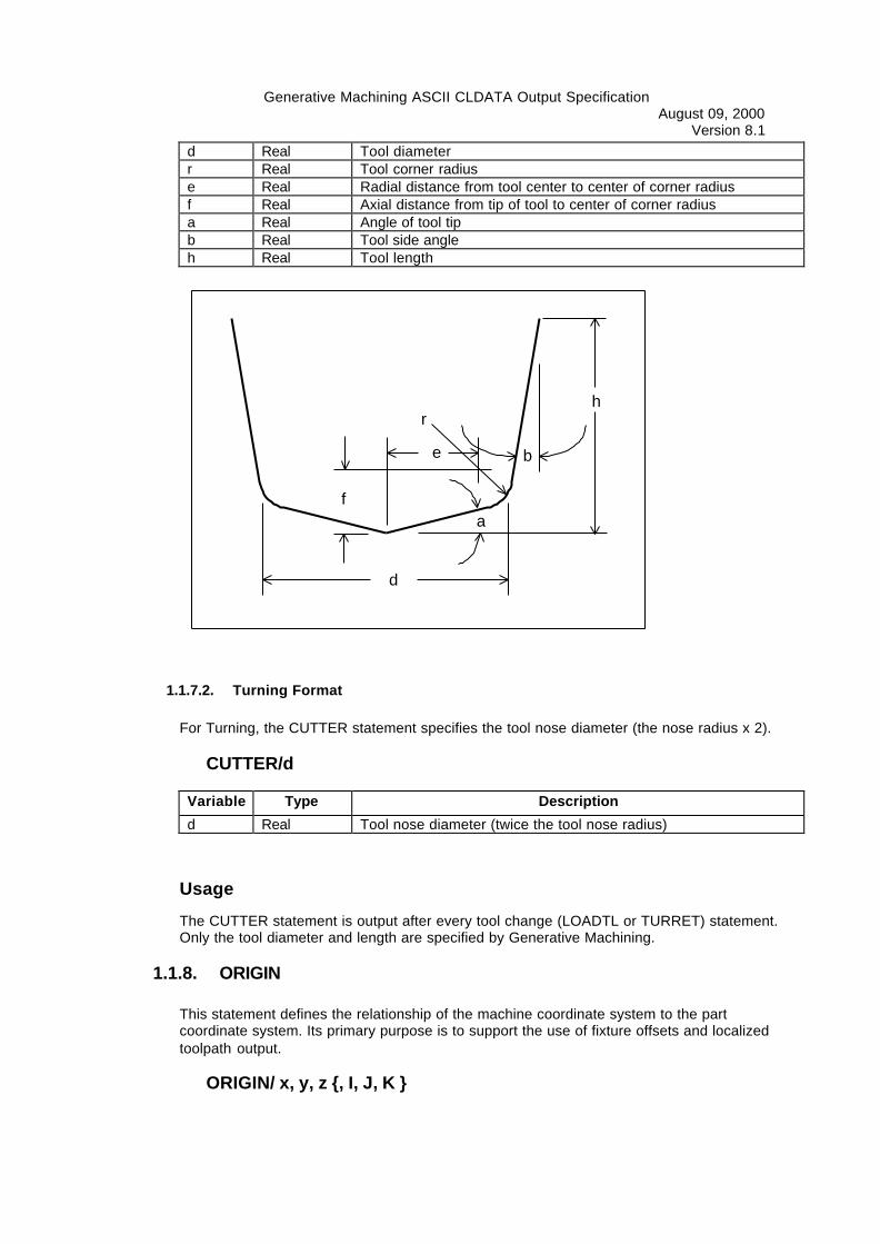
For Milling, the CUTTER statement is now specified using a seven parameter statementcontaining the values which define the cutter configuration used to compute the CLDATAlocations.
CUTTER/d, r, e, f, a, b, h
Variable Type Description
Generative Machining ASCII CLDATA Output SpecificationAugust 09, 2000
Version 8.1d Real Tool diameterr Real Tool corner radiuse Real Radial distance from tool center to center of corner radiusf Real Axial distance from tip of tool to center of corner radiusa Real Angle of tool tipb Real Tool side angleh Real Tool length
1.1.7.2. Turning Format
For Turning, the CUTTER statement specifies the tool nose diameter (the nose radius x 2).
CUTTER/d
Variable Type Description
d Real Tool nose diameter (twice the tool nose radius)
Usage
The CUTTER statement is output after every tool change (LOADTL or TURRET) statement.Only the tool diameter and length are specified by Generative Machining.
1.1.8. ORIGIN
This statement defines the relationship of the machine coordinate system to the partcoordinate system. Its primary purpose is to support the use of fixture offsets and localizedtoolpath output.
ORIGIN/ x, y, z {, I, J, K }
e
f
d
b
rh
a
Generative Machining ASCII CLDATA Output SpecificationAugust 09, 2000
Version 8.1
Variable Type Descriptionx Real The distance from the operation origin to the machine origin,
measured along the machine X axisy Real The distance from the operation origin to the machine origin,
measured along the machine Y axisz Real The distance from the operation origin to the machine origin,
measured along the machine Z axisI Real The X axis component of the tool axis (Operation Coordinate
System Z) vector for the operationJ Real The Y axis component of the tool axis (Operation Coordinate
System Z) vector for the operationK Real The Z axis component of the tool axis (Operation Coordinate
System Z) vector for the operation
Usage
The ORIGIN statement is used to specify the distance from the operation coordinate systemto the machine coordinate system and is output whenever this relationship changes. TheORIGIN XYZ values used are based upon the operation coordinate system used inGenerative Machining.
The ORIGIN statement is not used for Turning or MIll/Turn machines.
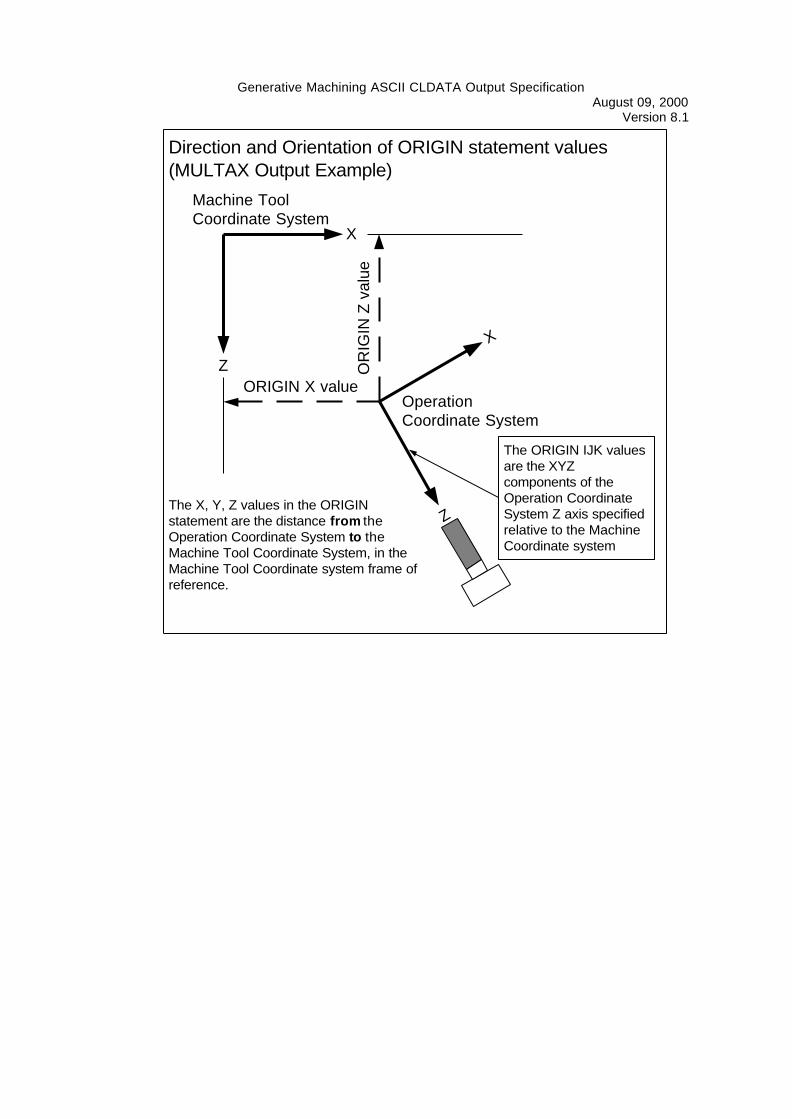
For MULTAX (IJK) output, the X, Y, Z values in the ORIGIN statement are the distance fromthe Operation Coordinate System to the Machine Tool Coordinate System, in the MachineTool Coordinate system frame of reference.
The IJK values are only output in MULTAX mode. Otherwise, only the translation (XYZ)values are output.
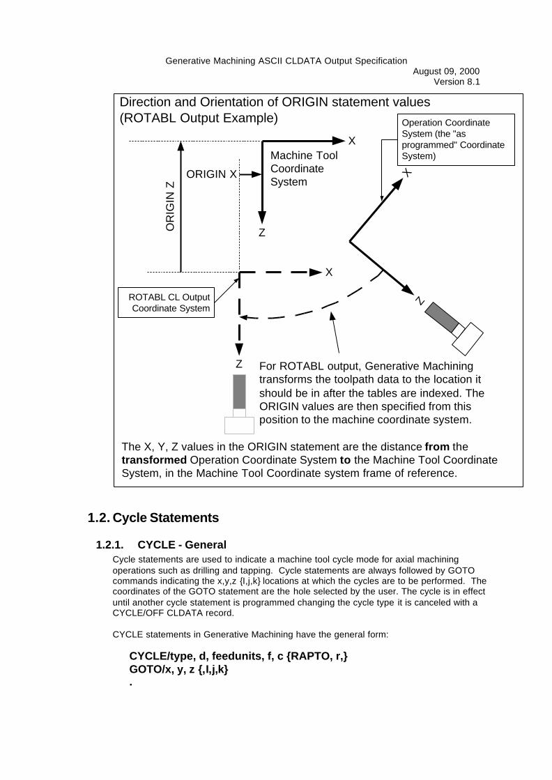
For ROTABL output, Generative Machining transforms the toolpath data (and hence, theoperation coordinate system) to the location it should be in after the tables are indexed. TheORIGIN values are then specified from the transformed location to the Machine ToolCoordinate System, in the Machine Tool Coordinate system frame of reference.
Generative Machining ASCII CLDATA Output SpecificationAugust 09, 2000
Version 8.1
X
Z
X
Z
Machine ToolCoordinate System
OperationCoordinate System
OR
IGIN
Z v
alue
ORIGIN X value
The X, Y, Z values in the ORIGINstatement are the distance from theOperation Coordinate System to theMachine Tool Coordinate System, in theMachine Tool Coordinate system frame ofreference.
Direction and Orientation of ORIGIN statement values(MULTAX Output Example)
The ORIGIN IJK valuesare the XYZcomponents of theOperation CoordinateSystem Z axis specifiedrelative to the MachineCoordinate system
Generative Machining ASCII CLDATA Output SpecificationAugust 09, 2000
Version 8.1
X
Z
XZ
Machine ToolCoordinateSystem
For ROTABL output, Generative Machiningtransforms the toolpath data to the location itshould be in after the tables are indexed. TheORIGIN values are then specified from thisposition to the machine coordinate system.
Operation CoordinateSystem (the "asprogrammed" CoordinateSystem)
X
Z
ORIGIN XO
RIG
IN Z
Direction and Orientation of ORIGIN statement values(ROTABL Output Example)
ROTABL CL OutputCoordinate System
The X, Y, Z values in the ORIGIN statement are the distance from thetransformed Operation Coordinate System to the Machine Tool CoordinateSystem, in the Machine Tool Coordinate system frame of reference.
1.2. Cycle Statements
1.2.1. CYCLE - GeneralCycle statements are used to indicate a machine tool cycle mode for axial machiningoperations such as drilling and tapping. Cycle statements are always followed by GOTOcommands indicating the x,y,z {I,j,k} locations at which the cycles are to be performed. Thecoordinates of the GOTO statement are the hole selected by the user. The cycle is in effectuntil another cycle statement is programmed changing the cycle type it is canceled with aCYCLE/OFF CLDATA record.
CYCLE statements in Generative Machining have the general form:
CYCLE/type, d, feedunits, f, c {RAPTO, r,}GOTO/x, y, z {,I,j,k}.

Generative Machining ASCII CLDATA Output SpecificationAugust 09, 2000
Version 8.1
.GOTO/x, y, z {,I,j,k}CYCLE/OFF
Variable Type Descriptiontype Text Cycle Type - BORE, BRKCHP, DEEP, DRILL, FACE, REAM, TAPd Real Depth - measured along the hole axis from the GOTO Z value to
the final depthfeedunits Text Feedrate type - IPM, IPR, MMPM, MMPRf Real Feedrate valuec Real Clearance Distance - the distance from the GOTO Z value to the
clearance plane, measured along the hole axisr Real Rapid Advance Distance - Measured along the hole axis from the
clearance plane value to the R plane (where the tool starts movingat feedrate).
Basic Cycle Example
This is theGOTO point
CYCLE/type, d, feedunits, f, cGOTO/x, y, z
Clearance Plane
GOTO Z value
Final Depth
c
d

Generative Machining ASCII CLDATA Output SpecificationAugust 09, 2000
Version 8.1
RAPTO Cycle Example
CYCLE/type, d, feedunits, f, c {,RAPTO, r} {,DWELL, h}GOTO/x, y, z
This is theGOTO point
Clearance Plane
GOTO Z value
Final Depth
c
d
Engage Plane
r
Usage
In any cycle, if the dwell value is 0 or is not set, the DWELL couplet must not be output.
When the CYCLE parameters are the same for multiple holes in a single operation, a singleCYCLE statement followed by several GOTO statements will be output.
1 32CYCLE/DRILL...GOTO/X1,Y1,Z1GOTO/X2,Y2,Z2GOTO/X3,Y3,Z3CYCLE/OFF
When a hole parameter changes, the CYCLE statement is restated with the changedparameters:
Generative Machining ASCII CLDATA Output SpecificationAugust 09, 2000
Version 8.1
1 32
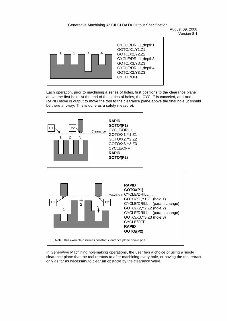
CYCLE/DRILL,depth1, ...GOTO/X1,Y1,Z1GOTO/X2,Y2,Z2CYCLE/DRILL,depth3, ...GOTO/X3,Y3,Z3CYCLE/DRILL,depth4, ...GOTO/X3,Y3,Z3CYCLE/OFF
4
Each operation, prior to machining a series of holes, first positions to the clearance planeabove the first hole. At the end of the series of holes, the CYCLE is canceled, and and aRAPID move is output to move the tool to the clearance plane above the final hole (it shouldbe there anyway. This is done as a safety measure).
1 32
RAPIDGOTO/(P1)CYCLE/DRILL...GOTO/X1,Y1,Z1GOTO/X2,Y2,Z2GOTO/X3,Y3,Z3CYCLE/OFFRAPIDGOTO/(P2)
P1Clearance
P2
RAPIDGOTO/(P1)CYCLE/DRILL,...GOTO/X1,Y1,Z1 (hole 1)CYCLE/DRILL... (param change)GOTO/X2,Y2,Z2 (hole 2)CYCLE/DRILL... (param change)GOTO/X3,Y3,Z3 (hole 3)CYCLE/OFFRAPIDGOTO/(P2)
Clearance
P1 P2
12
3
Note: This example assumes constant clearance plane above part
In Generative Machining holemaking operations, the user has a choice of using a singleclearance plane that the tool retracts to after machining every hole, or having the tool retractonly as far as necessary to clear an obstacle by the clearance value.
Generative Machining ASCII CLDATA Output SpecificationAugust 09, 2000
Version 8.1
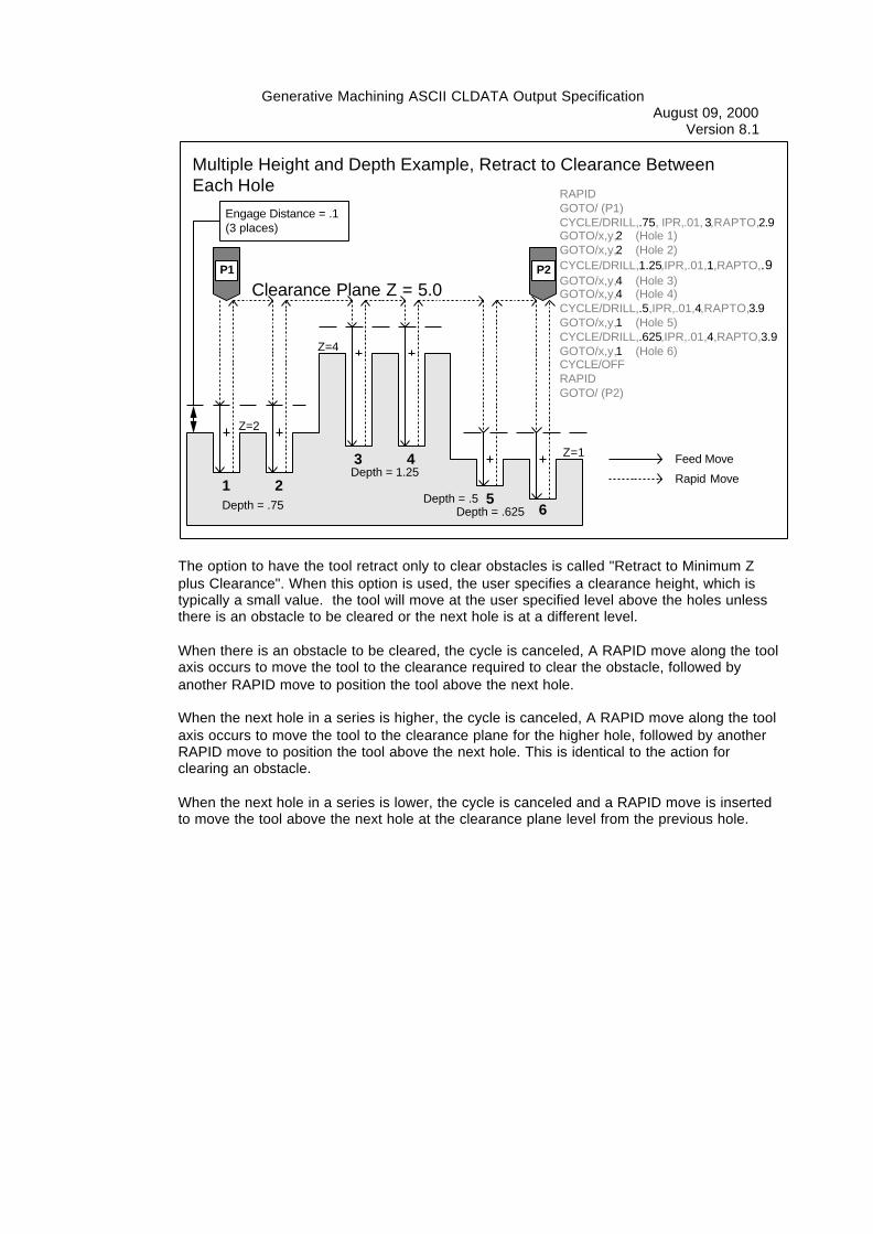
Multiple Height and Depth Example, Retract to Clearance BetweenEach Hole RAPID
GOTO/ (P1)CYCLE/DRILL,.75, IPR,.01, 3,RAPTO,2.9GOTO/x,y,2 (Hole 1)GOTO/x,y,2 (Hole 2)CYCLE/DRILL,1.25,IPR,.01,1,RAPTO,.9GOTO/x,y,4 (Hole 3)GOTO/x,y,4 (Hole 4)CYCLE/DRILL,.5,IPR,.01,4,RAPTO,3.9GOTO/x,y,1 (Hole 5)CYCLE/DRILL,.625,IPR,.01,4,RAPTO,3.9GOTO/x,y,1 (Hole 6)CYCLE/OFFRAPIDGOTO/ (P2)
1
3
2
4
56
Clearance Plane Z = 5.0
Engage Distance = .1(3 places)
Z=2
Depth = .75 Depth = .5
Depth = 1.25
Depth = .625
Z=1
Z=4
Feed Move
Rapid Move
P1 P2
The option to have the tool retract only to clear obstacles is called "Retract to Minimum Zplus Clearance". When this option is used, the user specifies a clearance height, which istypically a small value. the tool will move at the user specified level above the holes unlessthere is an obstacle to be cleared or the next hole is at a different level.
When there is an obstacle to be cleared, the cycle is canceled, A RAPID move along the toolaxis occurs to move the tool to the clearance required to clear the obstacle, followed byanother RAPID move to position the tool above the next hole.
When the next hole in a series is higher, the cycle is canceled, A RAPID move along the toolaxis occurs to move the tool to the clearance plane for the higher hole, followed by anotherRAPID move to position the tool above the next hole. This is identical to the action forclearing an obstacle.
When the next hole in a series is lower, the cycle is canceled and a RAPID move is insertedto move the tool above the next hole at the clearance plane level from the previous hole.

Generative Machining ASCII CLDATA Output SpecificationAugust 09, 2000
Version 8.1
Multiple Height and Depth Example, Retract Only to ClearObstacles
1
3
2
4
5
6
Clearance Plane Z = 5.0
Engage Distance = .1(3 places)
Z=2
Depth = .75
Depth = 1.25
Depth = 1.25
Depth = .625
Z=1
Z=4
Feed Move
Rapid Move
P1 P2
RAPIDGOTO/ (P1)CYCLE/DRILL,.75, IPR,.01, .1GOTO/x,y,2 (Hole 1)GOTO/x,y,2 (Hole 2)CYCLE/OFFRAPIDGOTO/x,y,4.1 (Above Hole 2)GOTO/x,y,4.1 (Above Hole 3)CYCLE/DRILL,1.25,IPR,.01,.1GOTO/x,y,4 (Hole 3)GOTO/x,y,4 (Hole 4)CYCLE/OFFRAPIDGOTO/x,y, 4.1 (Above Hole 5)CYCLE/DRILL,1.25, IPR,.01, .1GOTO/x,y,1 (Hole 5)CYCLE/DRILL,.625,IPR,.01,.1GOTO/x,y,1 (Hole 6)CYCLE/OFFRAPIDGOTO/ (P2)
Cycle is cancled to moveabove hole at higher level
Cycle is cancled to moveabove hole at lower level
1.2.2. CYCLE/ OFFThis statement cancels the previously programmed cycle.
CYCLE/ OFF
1.2.3. CYCLE/ DRILL
CYCLE/ DRILL,d, [ IPR | IPM | MMPR | MMPM ], f,c {,RAPTO,r}{,DWELL,[ q | REV, p]}
Variable Type Descriptiond Real Depth - measured along the hole axis from the GOTO Z value to
the final depthf Real Feedrate valuec Real Clearance Distance - the distance from the GOTO Z value to the
clearance plane, measured along the hole axisr Real Rapid Advance Distance - Measured along the hole axis from the
clearance plane value to the R plane (where the tool starts movingat feedrate).
q Real Dwell time in secondsp Real Dwell time in spindle revolutions

Generative Machining ASCII CLDATA Output SpecificationAugust 09, 2000
Version 8.1
1.2.4. CYCLE/ TAP
CYCLE/ TAP,d, [ IPR | IPM | MMPR | MMPM ], f,c {,RAPTO,r}
Variable Type Descriptiond Real Depth - measured along the hole axis from the GOTO Z value to
the final depthf Real Feedrate valuec Real Clearance Distance - the distance from the GOTO Z value to the
clearance plane, measured along the hole axisr Real Rapid Advance Distance - Measured along the hole axis from the
clearance plane value to the R plane (where the tool starts movingat feedrate).
1.2.5. CYCLE/ BOREThis cycle generates several boring output cycle statements depending on the optionsspecified.
CYCLE/ BORE,d, [ IPR | IPM | MMPR | MMPM ],f,c {,j } {,RAPTO,r}{,ORIENT {,a }} {,DWELL,[ q | REV, p]}
Variable Type Descriptiond Real Depth - measured along the hole axis from the GOTO Z value to
the final depthf Real Feedrate valuec Real Clearance Distance - the distance from the GOTO Z value to the
clearance plane, measured along the hole axisj Real Jog Distance (the ORIENT minor word must be specified)r Real Rapid Advance Distance - Measured along the hole axis from the
clearance plane value to the R plane (where the tool starts movingat feedrate).
a Real Orient Angle (the ORIENT minor word must be specified)q Real Dwell time in secondsp Real Dwell time in spindle revolutions
CYCLE/ REAMThe REAM cycle performs a "feed in - feed out" sequence of operations.
CYCLE/ REAM,d, [ IPR | IPM | MMPR | MMPM ], f,c {,RAPTO,r}{,DWELL,[ q | REV, p]}
Variable Type Descriptiond Real Depth - measured along the hole axis from the GOTO Z value to
the final depthf Real Feedrate valuec Real Clearance Distance - the distance from the GOTO Z value to the
clearance plane, measured along the hole axisr Real Rapid Advance Distance - Measured along the hole axis from the
clearance plane value to the R plane (where the tool starts movingat feedrate).
q Real Dwell time in seconds
Generative Machining ASCII CLDATA Output SpecificationAugust 09, 2000
Version 8.1p Real Dwell time in spindle revolutions
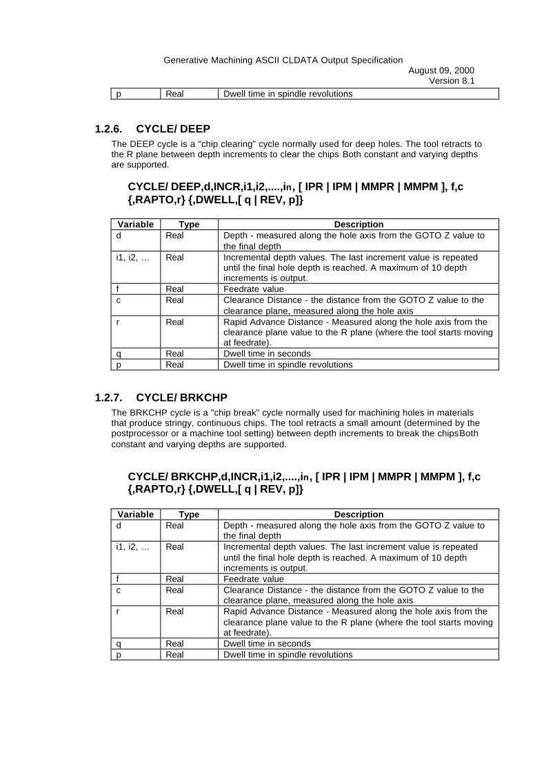
1.2.6. CYCLE/ DEEPThe DEEP cycle is a "chip clearing" cycle normally used for deep holes. The tool retracts tothe R plane between depth increments to clear the chips Both constant and varying depthsare supported.
CYCLE/ DEEP,d,INCR,i1,i2,....,in, [ IPR | IPM | MMPR | MMPM ], f,c{,RAPTO,r} {,DWELL,[ q | REV, p]}
Variable Type Descriptiond Real Depth - measured along the hole axis from the GOTO Z value to
the final depthi1, i2, … Real Incremental depth values. The last increment value is repeated
until the final hole depth is reached. A maximum of 10 depthincrements is output.
f Real Feedrate valuec Real Clearance Distance - the distance from the GOTO Z value to the
clearance plane, measured along the hole axisr Real Rapid Advance Distance - Measured along the hole axis from the
clearance plane value to the R plane (where the tool starts movingat feedrate).
q Real Dwell time in secondsp Real Dwell time in spindle revolutions
1.2.7. CYCLE/ BRKCHPThe BRKCHP cycle is a "chip break" cycle normally used for machining holes in materialsthat produce stringy, continuous chips. The tool retracts a small amount (determined by thepostprocessor or a machine tool setting) between depth increments to break the chipsBothconstant and varying depths are supported.
CYCLE/ BRKCHP,d,INCR,i1,i2,....,in, [ IPR | IPM | MMPR | MMPM ], f,c{,RAPTO,r} {,DWELL,[ q | REV, p]}
Variable Type Descriptiond Real Depth - measured along the hole axis from the GOTO Z value to
the final depthi1, i2, … Real Incremental depth values. The last increment value is repeated
until the final hole depth is reached. A maximum of 10 depthincrements is output.
f Real Feedrate valuec Real Clearance Distance - the distance from the GOTO Z value to the
clearance plane, measured along the hole axisr Real Rapid Advance Distance - Measured along the hole axis from the
clearance plane value to the R plane (where the tool starts movingat feedrate).
q Real Dwell time in secondsp Real Dwell time in spindle revolutions

Generative Machining ASCII CLDATA Output SpecificationAugust 09, 2000
Version 8.1
1.3. Machine / Postprocessor Control Commands
1.3.1. UNITSThe UNITS command specifies the CLDATA file units.
UNITS/ [INCHES | MM]
Usage
The UNITS command is output once to the CLDATA file.It is the second command in the file immediately following the PARTNO command.
1.3.2. AUXFUNThis statement is used to output a machine controller "M" code directly to the part program.
AUXFUN/ m ~[,m]
Variable Type Descriptionm Integer The M code (auxiliary function) code number.
Usage
AUXFUN is not output automatically by Generative Machining, but can be added by the uservia Transition moves or toolpath editing.
1.3.3. COOLNTThis statement is used to turn coolant on and off.
COOLNT/ [ ON | OFF | MIST | FLOOD | TAP | THRU ]
Usage
The COOLNT statement is output once at the beginning of an operation if the coolant modeis any of the "on" conditions (ON, MIST, FLOOD, TAP, THRU). A COOLNT/OFF statementis output at the end of the operation to turn off the coolant.
If coolant is specified to be off for the operation, no COOLNT commands are output (thecoolant is assumed to be turned off at the beginning of the operation since any operationspecifying coolant should have concluded with a COOLNT/OFF statement).
1.3.4. CUTCOMThis statement is used to turn cutter compensation on and off. It is also used to select theside, with respect to the following motion vector, that compensation will be applied to. It canoptionally specifiy the cutter compensation control register.
CUTCOM/ [RIGHT | LEFT] {,d}
Variable Type Descriptiond Integer The cutter radius compensation register number.

Generative Machining ASCII CLDATA Output SpecificationAugust 09, 2000
Version 8.1
CUTCOM/ON
This turns CUTCOM on, using the settings (plane, register, side, etc.) that were last used.Generative Machining does not create this form of the command, but it's possible to add itmanually via the toolpath editing capability.
CUTCOM/OFF
This form turns CUTCOM off.
Usage
CUTCOM commands can be generated for the Profile and Manual milling operations withthe "In-Plane" and "Circular" entry and exit types. CUTCOM commands can be added toother operations by editing the toolpath.CUTCOM for In-Plane Entries
The Entry and Exit length is the users clearancevalue plus the tool radius for the "ClearanceDistance" entry and exit types
1) The Start PointThe tool positions to this point atthe clearance plane, then descendsto the cut level
2) CUTCOM/ON, RIGHT
The curve selected for machining
TheEntry
The Exit4) CUTCOM/OFFThe exit is split 50% along it'sdistance when CUTCOM is used
CUTCOM is turned off at this pointfor exits other than In-Plane andCircular
The entry is split 50% along it'sdistance when CUTCOM is used
Generative Machining ASCII CLDATA Output SpecificationAugust 09, 2000
Version 8.1
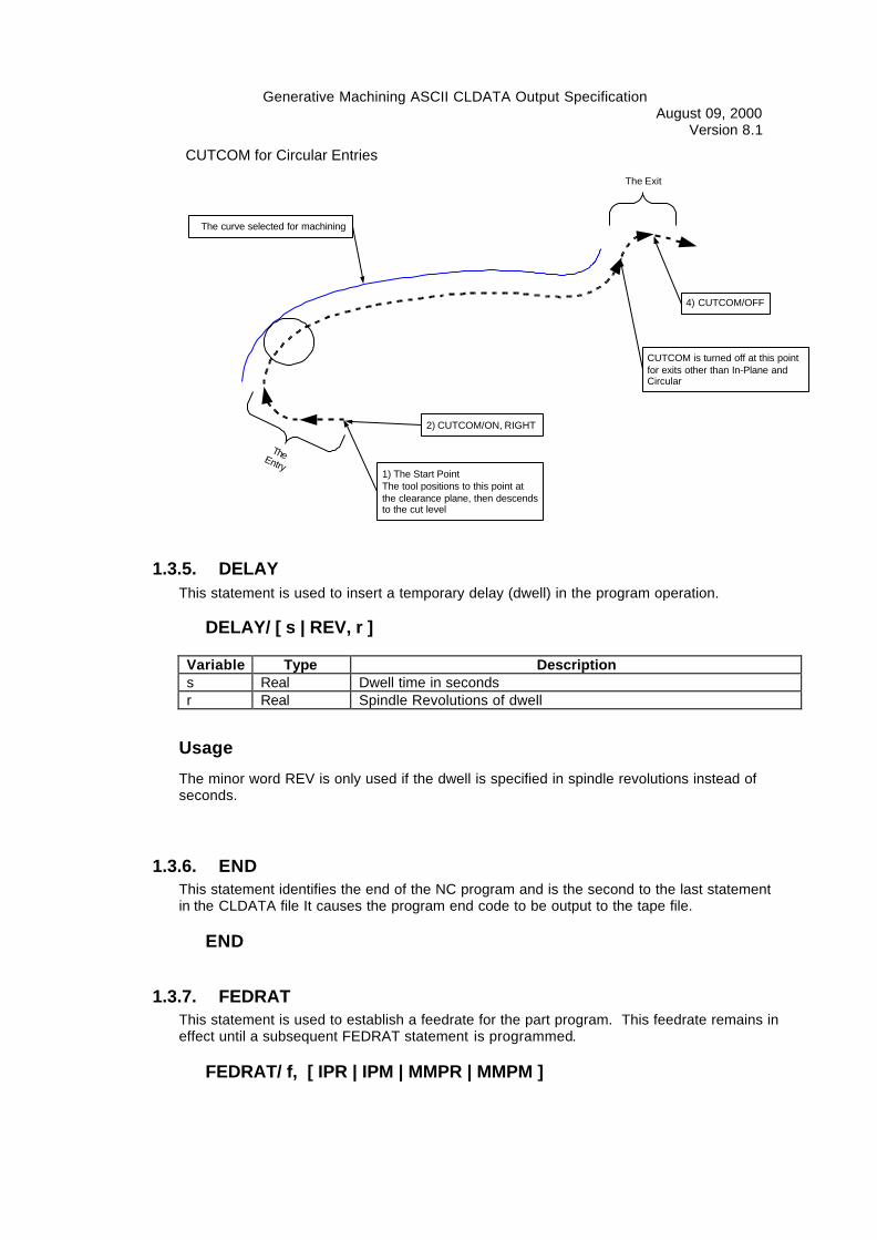
CUTCOM for Circular Entries
1) The Start PointThe tool positions to this point atthe clearance plane, then descendsto the cut level
2) CUTCOM/ON, RIGHT
The curve selected for machining
TheEntry
The Exit
4) CUTCOM/OFF
CUTCOM is turned off at this pointfor exits other than In-Plane andCircular
1.3.5. DELAYThis statement is used to insert a temporary delay (dwell) in the program operation.
DELAY/ [ s | REV, r ]
Variable Type Descriptions Real Dwell time in secondsr Real Spindle Revolutions of dwell
Usage
The minor word REV is only used if the dwell is specified in spindle revolutions instead ofseconds.
1.3.6. ENDThis statement identifies the end of the NC program and is the second to the last statementin the CLDATA file It causes the program end code to be output to the tape file.
END
1.3.7. FEDRATThis statement is used to establish a feedrate for the part program. This feedrate remains ineffect until a subsequent FEDRAT statement is programmed.
FEDRAT/ f, [ IPR | IPM | MMPR | MMPM ]
Generative Machining ASCII CLDATA Output SpecificationAugust 09, 2000
Version 8.1
Variable Type Descriptionf Real Feedrate
1.3.8. FINI
This is the last statement in the CLDATA file and indicates to the postprocessor that the endof the file has been reached.
FINI
1.3.9. HEAD
The HEAD statement is used to specify the current operation head, or turret.
HEAD/ [ 1 | 2 ]
Word Description1 Specifies the primary turret.2 Specifies the secondary turret.
Usage
The HEAD statement is output before the tool change (TURRET) to identify which turret isbeing used for the Lathe and Mill/Turn machine types.
1.3.10. INSERT
This statement is used to insert data directly into the machine program file withoutpostprocessor interpretation.
INSERT/'text'
Variable Type Descriptiontext text Up to 72 alphanumeric characters, including ( . , ) / - + * = and
blanks.
Usage
Note that in this format single quotes are required around the text.
1.3.11. LINTOL
The LINTOL statement is used for initiating a sequence which tests for non-linearity errorsand corrects them in accordance with a given Linear tolerance.
LINTOL/ t
Generative Machining ASCII CLDATA Output SpecificationAugust 09, 2000
Version 8.1Variable Type Descriptiont Real Linear tolerance
This format of the command specifies the linear tolerance values and starts LINTOLprocessing.
LINTOL/ [ ON | OFF ]
Word DescriptionON Starts LINTOL processing using the previously stated values.Off Terminates LINTOL processing.
Usage
LINTOL/ t specifies the linear tolerance and starts LINTOL processing.LINTOL is specified when performing Mill/Turn operations when the tool axis is parallel tothe Z axis of the lathe.LINTOL/ON is not used by Generative Machining (The form LINTOL/t is always output).
Generative Machining outputs LINTOL for milling operations on MILL/TURN machine tools,the 5-Axis projection operation, and the 5 axis holemaking operation. The value in theLINTOL statement is:
(Operation INTOL + Operation OUTOL) / 2
the lintol value is set in each operation and based on that operations average cut tolerance
1.3.12. LOADTL
This statement specifies the tool to be used in the following portion of the part program andsupplies the parameters for the tool. In I-DEAS, LOADTL statement is followed by theCUTTER statement.
LOADTL / t , IN, p, LENGTH, l , OSETNO, o
Variable Type Descriptiont Integer The tool number (Generative Machining "Post Tool ID").p Integer The station numberl Real The tool gage lengtho Integer The tool offset register number
1.3.13. MACHIN
This statement identifies the machine tool for which postprocessing is to occur. It alsopasses parameters to the post processor. All of the data after MACHIN/ is input by the useron the Machine definition form in Generative Machining.
MACHIN/textVariable Type Descriptiontext text User-supplied text.
Generative Machining ASCII CLDATA Output SpecificationAugust 09, 2000
Version 8.1
Usage
The user-supplied text comes from the secondary machine form.The MACHIN statement is output as the third statement in the CLDATA file. It is only outputif the toggle on the machine form is on.
1.3.14. MODE
The MODE statement is used to switch between milling and turning mode on Mill/Turnmachines.
MODE/ [ MILL | TURN ]
Word DescriptionMILL Selects Milling ModeTURN Selects Turning Mode
Usage
The MODE/MILL and MODE/TURN statements are output for all operations for all machinetypes.
The MODE/MILL or MODE/TURN statement is the first statement output for an operation.
1.3.15. OFSTNO
The OFSTNO command is used to change the tool offset register number of the current toolor to specify a fixture offset register number.
OFSTNO/o
Variable Type Descriptiono Integer The tool offset register number
OFSTNO/FIXTUR,o
Variable Type Descriptiono Integer The fixture offset number
Usage
Generative Machining only uses this statement to change the tool offset in turning finishgroove operations, where different offsets are available for the left and right side of thegroove. It can also be added via a Transiton move or a user CLDATA edit.
The fixture offset version of the command is output whenever the active fixture offsetchanges.

Generative Machining ASCII CLDATA Output SpecificationAugust 09, 2000
Version 8.1
1.3.16. OPSKIPThis statement causes the output of the "optional skip" code, indicating that all programmingstatement between ON and OFF can be ignored by the machine control at the operator'sdiscretion.
OPSKIP / [ON | OFF]
1.3.17. OPSTOP
This statement causes the output of the "optional stop" code, indicating a location where theprogram will stop at the operator's discretion.
OPSTOP
1.3.18. PARTNO
This statement lists the part program identifier. Contains the name of the Setup fromGenerative Machining.
PARTNO/'text'
Variable Type Descriptiontext text Up to 72 alphanumeric characters, including ( . , ) / - + * = and
blanks.
Usage
Note that this format of the PARTNO statement requires single quotes around the text.The PARTNO command is the first command in the CLDATA file.
1.3.19. PITCH
The PITCH statement is used to specify the parameters of the thread to be generated bysubsequent THREAD moves. This statement must always be given prior to a THREADstatement and is modal until changed.
PITCH/ p {,MULTRD, m} {[, INCR, pf | , DECR, pf ]}
Variable Type Descriptionp Real The number of threads per unit (inch or mm)MULTRD Minor Word Specifies a multiple start threadm Integer The number of thread startsINCR Minor Word Specifies an increasing variable thread leadDECR Minor Word Specifies a decreasing variable thread leadpf Real The lead change of the thread in units per revolution.
Usage
Generative Machining ASCII CLDATA Output SpecificationAugust 09, 2000
Version 8.1The PITCH statement only needs to be output once for a threading operation (Note: in thiscontext, "threading operation" refers to the entire set of motions needed to generate onecomplete thread feature).The PITCH statement must be output once for each threading operation, even if the value isthe same as that for a previous thread.The only formats used by Generative Machining are PITCH/p and PITCH/p,MULTRD,m ,where p is the pitch of the thread in the CLDATA file units and m is the number of starts for amultiple start thread.
1.3.20. PPFUN
PPFUN is never actually output by Generative Machining. For some third partypostprocessors, the PPFUN statement is used to change internal post options.
There is confusion surrounding the Cldata statement and the edit function labeled "PPFUN"in Generative Machining. The edit function is used to permit the user to add a CLDATA lineto the clfile. Anything that is typed into the text box on the Edit/PPFUN dialog is passeddirectly to the CLDATA file. For example, the if the user entered this statement into thetoolpath via the PPFUN function:
FOFF/4
It would appear in the cl edit form as:
PPFUN/FOFF/4
It would be output in the CLDATA as the user entered it:
FOFF/4
If the user wishes to output a PPFUN command, he would actually enter a PPFUNcommand in the PPFUN edit dialog in Generative Machining. It would appear in the cl editform like this:
PPFUN/PPFUN/1,2
Following the model above, the command would be output in the CLDATA file as:
PPFUN/1,2
1.3.21. PPRINT
This statement is used to print programmer comments.
PPRINT/'text'
Variable Type Descriptiontext text Up to 72 alphanumeric characters, including ( . , ) / - + * = and
blanks.
Generative Machining ASCII CLDATA Output SpecificationAugust 09, 2000
Version 8.1
Usage
Note that this format of the pprint statement requires single quotes around the text.
1.3.22. ROTABL
This statement indicates machine tool table rotation.
ROTABL/ a [ ,AAXIS | ,BAXIS | ,CAXIS ]
Variable Type Descriptiona Real Absolute table position angleAAXIS Minor Word Specifies the A rotary axis.BAXIS Minor Word Specifies the B rotary axis.CAXIS Minor Word Specifies the C rotary axis.
Usage
An axis identifier must be specified.In Generative Machining, only positioning of rotary tables is supported.ROTABL moves will be preceded by a RAPID command.
1.3.23. SPINDL
1.3.23.1. Mill Format
This statement specifies machine tool spindle parameters.
SPINDL/ s, RPM [ , CLW | , CCLW ] {, RANGE, r }
Variable Type Descriptions Real Spindle speed in revolutions per minuter Integer Spindle Range
This statement has an alternate form to turn the spindle on and off. The spindle parametersprogrammed in the previous SPINDL command are maintained:
SPINDL/ [ON, OFF]
Usage
Generative Machining does not output a spindle range for milling machines.Generative Machining does not output the SPINDLE/ON form of the command, but it can beadded by the user via Transition moves or the CLDATA editing function.

Generative Machining ASCII CLDATA Output SpecificationAugust 09, 2000
Version 8.11.3.23.2. Turning Format
The following is the SPINDL format for turning operations to specify RPM mode spindlespeeds:
SPINDL/ s, RPM [ , CLW | , CCLW ] , RANGE , n
Variable Type Descriptions Real Spindle speed in revolutions per minuten Integer Spindle range
The following is the SPINDL format for turning operations to specify constant surface speedmode spindle speeds:
SPINDL/ s [ , SFM | , SMM ] [ , CLW | , CCLW ] , MAXRPM, m,RANGE, n
Variable Type Descriptions Real Spindle speed in surface feet or surface meters per minutem Real Maximum spindle RPMn Integer Spindle Range
Usage
For constant surface speed mode Generative Machining outputs the spindle speed after thefirst motion command because some older machine tools require a X axis position to besupplied at the start of constant surface speed machining.
1.3.24. STOP
This statement causes the machine tool to stop.
STOP
1.3.25. THREAD
This statement causes a threading sequence to occur on the following linear move.
THREAD/ [ TURN | FACE | TAPER ]
Variable Type DescriptionTURN Minor Word Specifies a turning thread. The thread lead is specified along the
turning axis. Tapered threads, such as API threads, areconsidered TURN threads because the lead of the thread ismeasured along the part axis, not along the taper angle.
FACE Minor Word Specifies a face thread. The lead is specified along the face, orperpendicular to the turning axis. This is used for scrolls andgasket seating surfaces on flange faces.
TAPER Minor Word Specifies a taper thread. The thread lead is specified along the

Generative Machining ASCII CLDATA Output SpecificationAugust 09, 2000
Version 8.1thread angle.
Usage
Generative Machining supports onlyt the THEAD/TURN output.The THREAD statement only modifies the next GOTO move, so it must be restated for eachthread chasing pass.Thread parameters are determined by the PITCH command, which is modal and only needsto be stated once.
1.3.26. TURRET
This statement indicates that a new tool is to be used in the following portion of the partprogram and gives the parameters of the new tool.
TURRET/ t, IN, p, OSETNO, o, SETOOL, glx, 0, glz [ ,SETANG, xy,ATANGL, zx ]
Variable Type Descriptiont Integer The tool number (Generative Machining "Post Tool ID").p Integer Tool station numbero Integer Tool offset register numberglx Real X axis gage lengthglz Real Z axis gage lengthxy Real Tool axis angle in the XY plane (always 0 for Generative
Machining)zx Real Tool axis angle in the ZX plane (determined by the operation
coordinate system in Generative Machining)
An additional format to change the tool offset only is:
TURRET/t, OFFSTNO, o
Variable Type Descriptiono Integer Tool offset register number
Usage
The SETANG and ATANGL values are only specified for milling operations for Mill/Turnmachines.Generative Machining only supports tool angles in the ZX plane, so the xy angle value willalways be 0.
Generative Machining ASCII CLDATA Output SpecificationAugust 09, 2000
Version 8.1
2. Coordinate Systems
2.1. Mill
2.1.1. MULTAX (IJK) OUTPUT
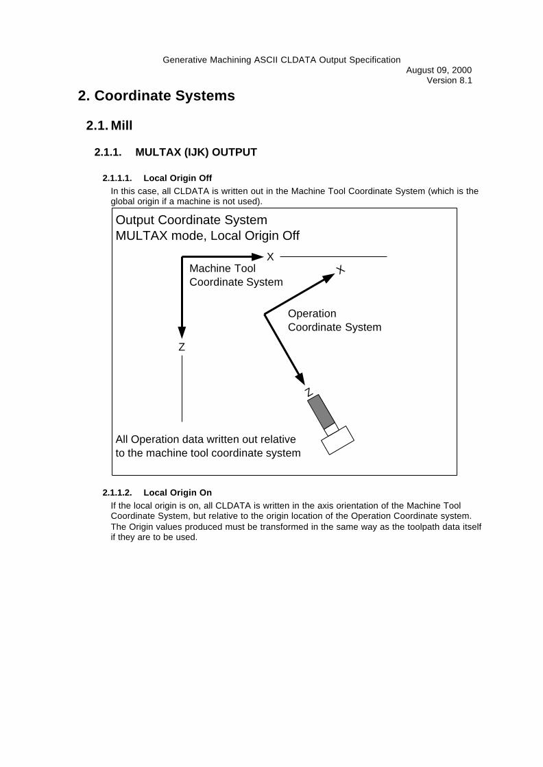
2.1.1.1. Local Origin OffIn this case, all CLDATA is written out in the Machine Tool Coordinate System (which is theglobal origin if a machine is not used).
X
Z
X
Z
Machine ToolCoordinate System
OperationCoordinate System
All Operation data written out relativeto the machine tool coordinate system
Output Coordinate SystemMULTAX mode, Local Origin Off
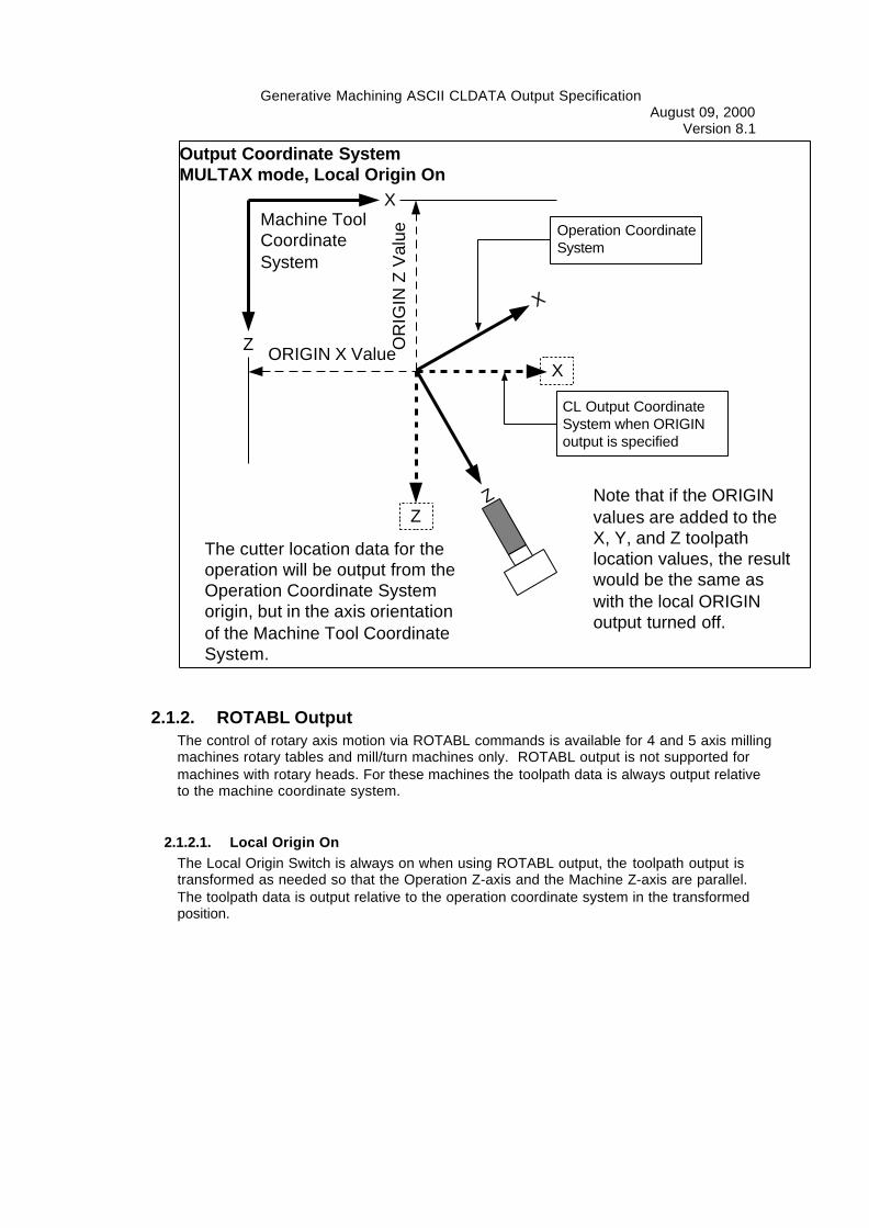
2.1.1.2. Local Origin OnIf the local origin is on, all CLDATA is written in the axis orientation of the Machine ToolCoordinate System, but relative to the origin location of the Operation Coordinate system.The Origin values produced must be transformed in the same way as the toolpath data itselfif they are to be used.
Generative Machining ASCII CLDATA Output SpecificationAugust 09, 2000
Version 8.1
X
Z
X
Z
Machine ToolCoordinateSystem
The cutter location data for theoperation will be output from theOperation Coordinate Systemorigin, but in the axis orientationof the Machine Tool CoordinateSystem.
Operation CoordinateSystem
X
Z
CL Output CoordinateSystem when ORIGINoutput is specified
OR
IGIN
Z V
alue
ORIGIN X Value
Output Coordinate SystemMULTAX mode, Local Origin On
Note that if the ORIGINvalues are added to theX, Y, and Z toolpathlocation values, the resultwould be the same aswith the local ORIGINoutput turned off.
2.1.2. ROTABL OutputThe control of rotary axis motion via ROTABL commands is available for 4 and 5 axis millingmachines rotary tables and mill/turn machines only. ROTABL output is not supported formachines with rotary heads. For these machines the toolpath data is always output relativeto the machine coordinate system.
2.1.2.1. Local Origin OnThe Local Origin Switch is always on when using ROTABL output, the toolpath output istransformed as needed so that the Operation Z-axis and the Machine Z-axis are parallel.The toolpath data is output relative to the operation coordinate system in the transformedposition.

Generative Machining ASCII CLDATA Output SpecificationAugust 09, 2000
Version 8.1
X
Z
XZ
Machine ToolCoordinate System
The toolpath data is transformed (rotated) asneeded to reflect the proper location after thetables are indexed. The output is then writtenrelative to the Operation Coordinate system inthe transformed location.
OperationCoordinate System
X
Z
CL Output CoordinateSystem when ORIGINoutput is specified
ORIGIN X
OR
IGIN
Z
Output Coordinate SystemROTABL mode, Local Origin On
2.2. LatheCldata for Lathes and Mill/Turns is always output relative to the machine coordinate system.There is no support for Fixture Offsets and localized toolpath data.The coordinate system for Lathes and Mill/Turns is defined as that of the machine tool, withthe Z axis being the axis of spindle rotation. Turning toolpaths are output in the ZX plane.
2.2.1. RearA "Rear" lathe is a machine for which the turret (or the primary turret for a dual turretmachine) is "above" the part when the ZX plane is viewed from above (looking in thenegative Y direction). I can also be thought of as a "1st quadrant" machine.

Generative Machining ASCII CLDATA Output SpecificationAugust 09, 2000
Version 8.1
Output Coordinate SystemRear Lathe
X
Z
This toolpath, for the rear orprimary turret, is output in the1st quadrant, with positive Xvalues
This toolpath, for the front, orsecondary turret, is output inthe 4th quadrant, withnegative X values
For a Rear Lathe, or a Dual Turret,Rear Primary Lathe, the X axis ofthe machine coordinate system isthe positive quadrant
Cldata OutputPositive X
Machine Tool Coordinate System(In Generative Machining)
2.2.2. FrontA "Front" lathe is a machine for which the turret (or the primary turret for a dual turretmachine) is "below" the part when the ZX plane is viewed from above (looking in thenegative Y direction). It can be thought of as a "4th" quadrant machine, however the X axis isreally inverted, so the output in the lower quadrant is positive.
Output Coordinate SystemFront Lathe
X
Z
This toolpath, for the rear orsecondary turret, is output in the 4thquadrant, with negative X values, butis displayed in the first quadrant.
This toolpath, for the front, orprimary turret, is output in the 1stquadrant, with positive X values,but is displayed in the 4th quadrant
Machine Tool Coordinate System
For a Front Lathe, or a Dual Turret,Front Primary Lathe, the X axis of themachine coordinate system is thenegative X, or secondary turretquadrant. This permits the user toswitch from a front definition to a reardefinition without changing themachine coordinate system.
Cldata OutputPositive X
(In Generative Machining)

Generative Machining ASCII CLDATA Output SpecificationAugust 09, 2000
Version 8.1The real distinction between the treatment for a front and a rear lathe is primarily the displayin Generative Machining. The output is always positive for the primary turret side of thecenterline and negative for the side opposite of the primary side. It's possible to program atool to move across the centerline, so positive or negative output can be generated for theprimary or the secondary turret. It is also possible to program a "front" lathe in "rear" lathemode. The output will be perfectly valid, but the view in I-DEAS will be inverted.
2.3. Mill/Turn
2.3.1. Turning OperationsThe output for turning operations on a mill/turn machine follows all of the rules described forturning above.
2.3.2. Milling Operations
2.3.2.1. Multax (IJK) Output
Milling operations for a mill/turn machine are output in the lathe machine tool coordinatesystem. This is exactly the same as the Generative Machining Machine Coordinate Systemfor a Rear lathe, and rotated 180 degrees around the Machine Coordinate System Z axis fora Front lathe (an inverted X axis).
2.3.2.2. ROTABL Output, Tool axis of 0,0,1 (Front Face Mill/Drill)In this case, the C axis is positioned to the 0-degree position (ROTABL/0) at the start of theoperation, and the output is in the turning center X, Y, and Z axis. The postprocessor has tomodify this output to be X, Z, and C axis rotation if the machine does not have a Y axis.
2.3.2.3. ROTABL Output, Tool axis other than 0,0,1 (Radial or Cross Mill/Drill)
If the tool axis of a milling operation is not 0,0,1, then a ROTABL command is output to indexthe C axis so that the operation coordinate system Z axis aligns with the turning center +Xaxis (primary turret) or -X axis (secondary turret). The toolpath is then transformed (rotatedaround the machine Z axis) to account for the rotary axis movement. This is the same as themilling case except the rotation is only done about Z.
Generative Machining ASCII CLDATA Output SpecificationAugust 09, 2000
Version 8.1
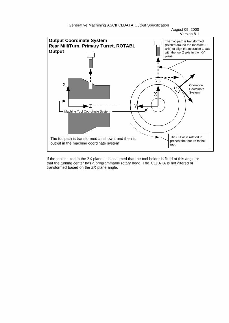
Output Coordinate SystemRear Mill/Turn, Primary Turret, ROTABLOutput
X
ZMachine Tool Coordinate System
The Toolpath is transformed(rotated around the machine Zaxis) to align the operation Z axiswith the tool Z axis in the XYplane.
OperationCoordinateSystemX
Y
The C Axis is rotated topresent the feature to thetool.
The toolpath is transformed as shown, and then isoutput in the machine coordinate system
If the tool is tilted in the ZX plane, it is assumed that the tool holder is fixed at this angle orthat the turning center has a programmable rotary head. The CLDATA is not altered ortransformed based on the ZX plane angle.

Generative Machining ASCII CLDATA Output SpecificationAugust 09, 2000
Version 8.1
Output Coordinate SystemRear Mill/Turn, Primary Turret, ROTABLOutput
X
ZMachine Tool Coordinate System
The Toolpath is transformed(rotated around the machine Zaxis) to align the operation Z axiswith the tool Z axis in the XYplane.The toolpath is not
transformed to accountfor the tool angle in theZX plane. This angle isprovided to the post viathe TURRET command
OperationCoordinateSystemX
Y
The C Axis is rotated topresent the feature to thetool.
The toolpath is transformed as shown, and then isoutput in the machine coordinate system
3. Output Order and Modal CommandsThe basic, standard, output order of CLDATA commands from Generative Machining is:
3.1. Beginning of the cldata fileThe following commands are output at the beginning of the CLDATA file:
PARTNO Contains the name of the Setup
UNITSPPRINT… Setup Note PPRINT statements (if any setup notes exist)
Note: This is output once per clfile. If more than one setup is selected for output, this data isoutput only once at the beginning.
3.2. For Each OperationMODE The MODE statement is the first thing output for each operation, and is
always output.PPRINT… Operation Note PPRINT statements, if any operation notes exist.
HEAD The HEAD command is only output for multiple turret lathe and mill/turnmachines.
FROM The FROM statement is output here if appropriate (see the FROMstatement Usage Notes)
LOADTL Output if the tool changes (if any tool data changes). This could be thesame tool with a new offset, for example.
Generative Machining ASCII CLDATA Output SpecificationAugust 09, 2000
Version 8.1
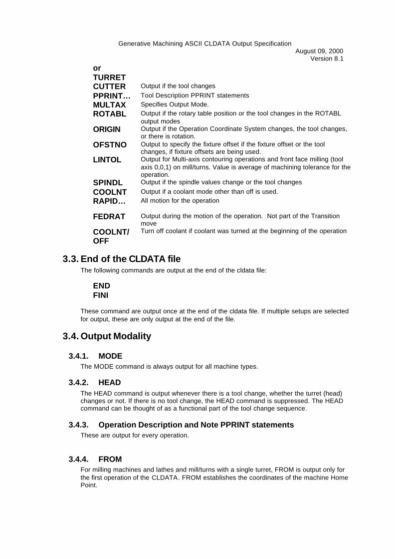
orTURRETCUTTER Output if the tool changes
PPRINT… Tool Description PPRINT statements
MULTAX Specifies Output Mode.
ROTABL Output if the rotary table position or the tool changes in the ROTABLoutput modes
ORIGIN Output if the Operation Coordinate System changes, the tool changes,or there is rotation.
OFSTNO Output to specify the fixture offset if the fixture offset or the toolchanges, if fixture offsets are being used.
LINTOL Output for Multi-axis contouring operations and front face milling (toolaxis 0,0,1) on mill/turns. Value is average of machining tolerance for theoperation.
SPINDL Output if the spindle values change or the tool changes
COOLNT Output if a coolant mode other than off is used.
RAPID… All motion for the operation
FEDRAT Output during the motion of the operation. Not part of the Transitionmove
COOLNT/OFF
Turn off coolant if coolant was turned at the beginning of the operation
3.3. End of the CLDATA fileThe following commands are output at the end of the cldata file:
ENDFINI
These command are output once at the end of the cldata file. If multiple setups are selectedfor output, these are only output at the end of the file.
3.4. Output Modality
3.4.1. MODEThe MODE command is always output for all machine types.
3.4.2. HEADThe HEAD command is output whenever there is a tool change, whether the turret (head)changes or not. If there is no tool change, the HEAD command is suppressed. The HEADcommand can be thought of as a functional part of the tool change sequence.
3.4.3. Operation Description and Note PPRINT statementsThese are output for every operation.
3.4.4. FROMFor milling machines and lathes and mill/turns with a single turret, FROM is output only forthe first operation of the CLDATA. FROM establishes the coordinates of the machine HomePoint.

Generative Machining ASCII CLDATA Output SpecificationAugust 09, 2000
Version 8.1
For dual turret lathes and mill/turns, FROM is output on the first operation to establish thehome point for the first turret used, and a second FROM is output on the first operation usingthe other turret to establish the home point for that turret.
3.4.5. TURRET or LOADTLIf a different tool is specified(see the CLDATA vocabulary sections for LOADTL andTURRET), the toolchange will be output.If no tool parameters change, the tool change output to CLDATA will be suppressed, with theexceptions noted below.
The tool change resets the modal behavior for all other operation commands. For example, ifthe tool changes but the spindle speed is the same, the spindle command is still output.
3.4.5.1. Threading Gage PassThe tool change and spindle commands are restated after the program stop in a threadinggage pass. This allows the offset portion of the tool change to be restated if needed, toensure that any changes to the compensation value are activated. The spindle is turned offby a program stop, allowing the spindle command to be restated.
3.4.5.2. Finish Grooving
The finish grooving operation can change tool offsets in the middle of the operation. If thesame tool is used in an operation following the finish groove operation, the tool change isrestated to ensure that the "primary", or leading edge offset, is reinstated.
3.4.6. CUTTERThe cutter statement is output whenever a tool change is output. It is paramter APTstandard format.
3.4.7. Tool Description PPRINT statementsThe tool description PPRINT statements are output from Generative Machining whenever atool change is output.
3.4.8. MULTAXThis statement is output whenever the tool changes or when the MULTAX mode changes.
3.4.9. ROTABLThe ROTABL statement(s) is output whenever the tool changes or when the table positionchanges.
3.4.10. ORIGINThe ORIGIN statement is output whenever the tool changes or when the ORIGIN valueschange (different Operation Coordinate System).
3.4.11. OFSTNOThe OFSTNO statement is output whenever the tool changes or when the fixture offsetchanges (different Operation Coordinate System).

Generative Machining ASCII CLDATA Output SpecificationAugust 09, 2000
Version 8.1
3.4.12. LINTOLThe LINTOL statement is output whenever the tool changes or when the LINTOL valueschange.LINTOL is only output for multi-axis contouring or mill/turn front face (tool axis 0,0,1) work.
3.4.13. SPINDLThe SPINDL statement is output whenever the tool changes, or when the SPINDL valueschange (any spindle value).
3.4.14. COOLNTThe COOLNT statement is output for every operation that uses any mode of coolant (ON,FLOOD, MIST, TAP, THRU). If coolant is off for the operation, no COOLNT command isoutput. If coolant is turned on at the beginning of the operation, it is turned off at the end.