the of saturated water vapor in range -...
TRANSCRIPT

THE PRESSURE OF SATURATED WATER VAPOR IN THERANGE 100° TO 374° C.
By N. S. Osborne, H. F. Stimson, E. F. Fiock, and D. C. Ginnings
ABSTRACT
The method and apparatus employed, and the measurements made in thisdetermination of the vapor pressure of water are described, and the resultsobtained are given and formulated.The method used was the "static method" in which the pressure is determined
at the stationary boundary between the liquid and the vapor in equilibrium at acontant temperature in a closed container.The container for the water sample was a calorimeter specially built for high
pressure work. Pressures were measured by a precision piston gauge whichbalances the pressure by the gravitational force on a piston loaded with weights.Temperatures were measured by platinum resistance thermometers supple-mented by thermoelements.A total of 394 measurements were made at 38 temperatures so distributed as
to facilitate formulation of the pressure-temperature relation.
The formulation was made by using an empirical equation which was fitted
to the results in two temperature ranges. Values of pressure and its derivative
with respect to temperature are tabulated from this formulation in standardatmospheres, centibars, and kg/cm2 at each degree centigrade, and in pounds per
square inch at each degree Fahrenheit. This provides a mutually consistent
group of vapor pressure tables in convenient form for practical working tables of
fundamental steam data.It is estimated that the results are reliable to 3 parts in 10,000.
CONTENTSPage
I. Introduction 1 55
II. Method and apparatus 156
1. General description 156
2. Calorimeter shell : 158
3. Calorimeter heater 158
4. Heater diffuser 159
5. Envelope 159
6. Connections to the calorimeter shell 160
7. Pressure connections and auxiliary indicators 160
8. Pressure gaugeJj>2
9. Thermometric installation 163
(a) Reference blockJj>»
(6) Thermoelements 163
(c) Resistance thermometersIII. Experimental procedureIV. Results of measurements }^°V. Formulation of results
VI. Estimation of accuracy *°°
VII. Acknowledgment 188
I. INTRODUCTION
The relation between the temperature and the pressure of satu-
rated water vapor is of prime importance in establishing the thermo-
dynamic behavior of steam. This relation, commonly called the vapor
pressure relation, is a characteristic property which can be observed
155

156 Bureau of Standards Journal of Research [Voi.io
directly. Moreover, its derivative is an essential factor in correlating
other important thermodynamic properties. It is evident that ade-
quate knowledge of this property is indispensable to the success of
any systematic effort to determine and formulate the thermal prop-erties of steam.The vapor pressure measurements to be described here were made
as a coordinate part of the larger and more formidable project of calori-
metric measurement of the enthalpy (heat content) of saturated waterand steam. Since pressure and temperature of saturated vapor are
definitely related, measurements of other thermal properties may bereferred to either temperature or pressure as an independent variable,
depending on which is the more expedient. This characteristic wasutilized in planning a new high pressure calorimetric 1 apparatus for
surveying the bahavior of saturated steam. As a refinement in tech-
nique, provision was made for observing both the temperature andthe pressure of a water sample in the calorimeter. The arrange-ments for control and measurement of temperature, and for trans-
mission of pressure to the measuring gage, were perfected to a degreewhich permits the rapid and reliable measurement of saturation pres-
sure in the range 100° to 374° C.Measurements within this range have already been made in several
laboratories in accordance with definitely specified, recognizedstandards, permitting reduction of the results to a common basis.
The results of these independent determinations, differing con-siderably in method and technique, have been regarded as in virtual
agreement for technical purposes. Nevertheless, close scrutiny dis-
closed discrepancies which seemed unnecessarily large, particularly
in the derivative on which reliance must be placed for making thermo-dynamic correlations of other experimental data.The equipment available in this laboratory provided a favorable
opportunity for making vapor pressure measurements. These wereundertaken prior to the calorimetric measurements with the objectof further verifying the numerical values of this property.To provide for trustworthy correlation of thermodynamic prop-
erties, it is necessary not only that the observations of the cor-
responding pressures and temperatures be adequate in number,distribution, and precision, but also that a formulation be usedwhich yields reliable values of the derivative. This latter require-ment has been met by the successful application of a type of empiricalequation which conforms with remarkable fidelity to the observedbehavior of saturated steam.
II. METHOD AND APPARATUS
1. GENERAL DESCRIPTION
In the calorimetric equipment used in making the vapor pressuremeasurements, provision is made for observing temperature, pressure,mass of water sample, and the energy added. The arrangementsprovided for controlling the state of the fluid in the calorimetricexperiments are also especially appropriate for the determination ofvapor pressure. In this report, which concerns only the latter, the
» Mechanical engineering, vol. 54, No. 2, p. 118, 1932.

Otborne, StimsoniFiock, Oinnings J
Pressure of Saturated Water Vapor 157
description is intended to record those features which are essential
to the vapor pressure measurements.A schematic diagram of the vapor pressure measuring equipment
is shown in Figure 1. The metal calorimeter shell contains, besides
the water sample, an electric heater and a system of radial silver
plates for diffusing heat. This shell is suspended within a thermallycontrolled inclosure or envelope which shields it against heat exchangewith the surroundings.
f%- -u>
-v
r :\
~±
= F
v|w
Figure 1.
—
Schematic diagram of (he vapor pressure measuring equipment
A, high pressure air.
C, calorimeter shell (special steel)
.
D, heat diffusing system (silver).
E, envelope (silver)
.
F, water container (silver).
H, electric heater.
7, water indicator (glass capillary).
J, oil indicator (glass capillary).
0, air vent.P, piston.
R, reference block (silver)
.
U, union.V, valves.W, weights.Y, vacuum connection.Z, pressure transmission cell.
The pressure in the calorimeter is transmitted directly through a
tube from the bottom of the calorimeter shell to a cell with a thin
elastic metal diaphragm which readily transmits pressure yet pre-
vents escape of the water sample. The pressure in the calorimeter
is thus transmitted through this sensitive diaphragm to a column
of water, and through this column to a balancing artificial atmos-
phere of air. The meniscus between the water and air is visible in
a glass capillary, and serves to indicate balance between the air
pressure and the pressure in the calorimeter. The pressure ol ,the
artificial atmosphere which is subject to very delicate manual control,
is transmitted to the measuring piston gage through an oil column
The air-oil meniscus is visible in another glass capillary and is used
as an indicator to show when the piston is properly loaded.

158 Bureau of Standards Journal of Research [Vol. 10
The temperature of the water sample, which is observed after the
load on the piston has been properly adjusted, is obtained by thecombined use of platinum resistance thermometers and thermoele-ments. Resistance thermometers located in a reference block of
thick silver, yield the temperature of the block according to theinternational temperature scale. The thermoelements, with principal
junctions distributed on the shell and reference junctions located
on the reference block, indicate the small differences which exist
between the calorimeter and the reference temperature. Thethermoelements can be used in series to indicate average temperatures,or individually to indicate local temperatures. A diagrammaticscale drawing of the assembled apparatus is shown in Figure 2.
The principal parts will be described in detail forthwith.
2. CALORIMETER SHELL
The calorimeter shell shown at C in Figure 2 provides a receptacle
for the sample of water so that its thermal behavior may be observed.It has the shape of a cylinder with hemispherical ends and, as assem-bled with the various accessory parts in place, will hold approximately320 cm3
. The material is a special alloy steel containing about19 per cent chromium, 7.5 per cent nickel, 4.5 per cent tungsten, 1.3
per cent silicon, 0.5 per cent manganese, and 0.46 per cent carbon.This material was chosen because of its resistance to creep and to
attack by water at temperatures up to 400° C. The shell wasmachined from a solid bar and was made in two similar parts heldtogether on a thin silver gasket by the tension developed in theright and left threaded band which is screwed on with powerfulwrenches engaging machined lugs. This annular joint was formedby machining one member to a plane surface and the other to ablunt angled edge, giving a contact with the silver gasket of about ahalf millimeter width. All parts were accurately machined and thesurfaces well polished.
The shell, having a thickness of 0.125 inch (3.2 mm), was designedto stand steam pressures up to the critical without permanent deforma-tion. Actually in hydraulic proof tests, it showed no permanentstretch for an internal pressure of 4,500 lbs./inch 2
. After carryinga charge of water at 350° C, the inner surface showed on examinationno sign of attack by the water other than the formation of a verythin film of light-straw color similar to that formed on the outsidewhere in contact with air.
3. CALORIMETER HEATER
The electric heater in the calorimeter shell, shown at Hi (fig. 2)is an insulated resistor encased in a metal tubular coil sealed her-metically to the shell. It consists of about 10 ohms of calido wire,
0.2 mm in diameter, with gold leads. This resistor was wound in
helical form, 0.6 mm outside diameter, and embedded in magnesiafor insulation. It was sheathed in a platinum tube drawn downtightly on the magnesia to an outside diameter of about 2 mm.This sheathed resistor was then bent into the form of a helical coil
12 mm outside diameter, the resistor occupying about two turns.
Each projecting end of this heater was put through a threaded plugof silver-palladium ahoy and sealed by soldering with gold. To

Figure 2.—Sectional scale drawing of vapor pressure
A, high pressure air Inlet.
I., ruulm u m(
'' r shell (special steel).
-This is not a true section bul
O, guard (silver).
Wi, Hs, etc., electric heaters.
, „ imlicin'" <-':' .i .-..i-.iU-.l-N
./'. ,,i| | L„li, ir.l !;!.' Ci.piUlO'.Vl.
it, casing \.uia;
M, gear drive.
of important parts projected i
N, rotating arms.
0, air vent.
P, piston.
Q, oil pump.R, reference block (sdver).
,s shields uduminnm).
T, platinum resistance thermometers.
V, valves.W, weights.Y vacuum connection.''
n,e'-me i.inr.missiou cell.
,,', ,!,, principal junctions of thermoelement!..
152894—33. (Face p. 168.)
fSSTSiSSr] Pressure of Saturated Water Vapor 159
complete the seal, the shoulders of these plugs were drawn tightlyon thin silver gaskets by threaded nuts outside the shell.
The design of this heater was chosen with regard to influence onthe calorimetric performance of the instrument. The heater surfacehas been made small with three objects in view, namely, to avoidunnecessary heat capacity, to permit operation with small amountsof liquid, and to avoid excessive accumulation of energy as superheatin the liquid. The characteristics of the heater have relatively little
to do with the technique of pressure measurements since it is usedonly for bringing the water sample to a desired temperature.
4. HEAT DIFFUSER
For promoting temperature equalization in the calorimeter shell,
a system of heat-conducting plates is provided. This heat-diffusingsystem consists of 30 flat plates of silver 0.5 mm thick, shaped toconform to the vertical profile of the shell and held radially in twoslotted hubs so as to penetrate and interconnect the space withinthe shell with a good heat conductor. The chief function of this
arrangement is to hasten the equalization of temperature after aperiod of change. This feature is important in both the calori-
metric and the pressure measurements, and to some extent com-pensates for the lack of positive circulation by mechanical means.
5. ENVELOPE
The principal purpose of the envelope which surrounds the calo-
rimeter shell is to provide protection from fortuitous exchanges of
heat. This feature, which is vital to the energy accounting in
calorimetry, contributes to the suitability of the instrument for
pressure measurements by favoring the attainment of thermalequilibrium of the water sample and its container.
This protecting envelope is a double-walled inclosure formed of
two coaxial cylindrical silver shells with flat ends, the inner one6.3 mm thick and the outer one 3.2 mm thick, which will be desig-
nated as "envelope" and "guard" respectively. Electric heating
elements are distributed over the outer surfaces of these shells.
Subdivision of these heaters provides for meeting various local
thermal requirements. The heater on the envelope is used only
when its temperature is being raised. The guard may also be heated
at a controlled rate, or its temperature may be maintained auto-
matically at any desired value by a sensitive thermoregulator using
a platinum resistance thermometer.At a steady temperature the guard heater supplies the heat lo-ss
to the outside while the envelope temperature remains fixed. Such
conditions are favorable for the establishment and maintenance of
temperature equality of the calorimeter and its contents.
In the space outside the guard two thin aluminum shields are
placed to impede the loss of heat by radiation and convection. These
light shields, 0.05 mm thick, furnish effective thermal insulation and
prevent excessive heat loss without introducing any considerable
thermal lag. The whole is inclosed in a heavy brass casing which
serves not only as a cover but also as protection in case of an explo-
sive failure.

160 Bureau oj Standards Journal oj Research [Vol. w
6. CONNECTIONS TO THE CALORIMETER SHELL
The calorimeter shell is held in place by two tubes of silver-
palladium alloy. The one at the top bears the weight of the shell
and the one at the bottom centers it. Besides furnishing firm,
thermally resistant support for the shell, these tubes serve also for
the transfer of fluid to or from the calorimeter. The upper tube is
intended for a vapor outlet to be used in calorimetric measurementsof heat of vaporization and was temporarily closed during the pres-
sure measurements by a disk in the union at the top of the shell.
This suspension tube reaches from the body of the vapor valve whichis carried on a light but firm support from the guard shell.
The lower tube is used as a connection to transfer liquid to or fromthe calorimeter, and also to transmit pressure from within to theauxiliary measuring equipment outside. A cylindrical brass cell for
cooling water surrounds this tube where it passes through the outerbrass casing. Where the tube passes through the outer silver guardshell it bears an electric heater mounted on a silver support attachedto the tube. There is a free length of about 2.6 cm between this
heater and the union at the shell. The purpose of the heater is to
control the thermal gradient in this section of the tube as indicatedby thermoelements installed for that purpose. Similarly, the gradi-
ents on the upper tube are controlled by a heater on the vapor valvebody.The lower tube is always filled with liquid while observing satura-
tion behavior in the calorimeter. From a union just below the coolingcell at the bottom, connection is made through a copper-nickel tubeto the liquid valve and the pressure transmission cell. Beyond theliquid valve the line extends to a union by which the water receiver
with its valve is connected. A side connection leads through a valveto a vacuum pump to permit evacuation of the calorimeter and its
connecting lines.
7. PRESSURE CONNECTIONS AND AUXILIARY INDICATORS
Pressure is transmitted from the free surface of the liquid in thecalorimeter through a continuous column of liquid water to the elastic
diaphragm of the pressure transmission cell to be described forthwith.The purpose of this cell is to allow the pressure in the calorimetersystem to be communicated to the pressure measuring gage, whileat the same time interposing a barrier to the escape of water fromthe system through the gage line. A limited amount of inward andoutward movement is allowed the water column by the necessaryflexibility of the transmitting device, but this movement is restricted
to the small volume displacement of 0.04 cm3 required for observa-tion. In this transmitting cell, a circular diaphragm of thin silver
about 3 cm in diameter is held under slight tension between the twoparts of the cell which clamp the diaphragm tightly near the edge.Small pressure changes suffice to move the diaphragm back and forthacross the space between the two parts. The inner cell walls areshaped to conform approximately to the figure of the distended dia-phragm. The delicate diaphragm must encounter support from thecell walls to avoid deformation beyond its elastic limit when thepressures are far out of balance.

fu£™Ginning*1
]Pressure of Saturated Water Vapor 161
The cell is made of two disks of stainless steel, each about 5 cm indiameter and about 1.4 cm thick, provided with 12 screws to drawthem tightly together on the silver diaphragm. The two partshave nipples with unions for making connections with the lines asshown. The apertures to the inner cell are made only 0.035 cm indiameter to avoid too large an unsupported area of the thin silverdiaphragm. This diaphragm is a vital part of the device, and its
characteristics determine the limit of sensitivity of the transmittingcell. It is of rolled sheet silver about 0.06 mm thick. The diaphragmand cell were put together at a temperature of about 150° C. inorder to produce sufficient tension, when cooled, to flatten out theslight unevenness of the sheet which otherwise would interfere withthe freedom of motion between the cell walls. This procedure left
enough flexibilit}7 to give a satisfactory sensitivity to pressure change.On the measuring or gage side of the diaphragm a continuous
column of liquid water extends and transmits pressure to air at themeniscus boundary in a glass capillary indicator. The volume ofthis water column is small. The meniscus is a reliable indicator of theposition of the diaphragm and is used as a null device to tell when thepressures on the two sides are balanced to bring the diaphragm to achosen zero position near the neutral. The air column extends to
the end of an oil column in a second glass capillary indicator, whencethe pressure is transmitted through the oil directly to the piston of
the measuring gage. Sensitive needle valves permit fine adjustmentof the pressure in the air line to balance the pressure in the calorim-
eter. When these pressures are balanced and the piston gage is also
balanced by weights, the vapor pressure in the calorimeter may befound from the pressure measured at the piston by taking into
account the fluid columns between the piston and the free surface in
the calorimeter and whatever pressure difference the diaphragm maysupport.The fluid columns to be accoimted for are the oil, air, and water
columns. The oil-column correction is constant and is easily meas-ured. The air-column correction depends on the pressure and is
almost negligible. The correction for the water column is somewhatmore complicated due to the variation of the position of each end.
The position of the meniscus in the glass capillary is directly observed
and easily corrected for in each measurement. From a reference point
on this capillary to a point near the calorimeter there is a constant
pressure correction which is computed from the difference in height.
From this latter point to the free surface the pressure correction varies
both with the filling in the calorimeter and with its temperature, and
was computed for the conditions of each measurement.
The correction for pressure difference supported by the diaphragm
is small, but arises because the chosen zero position is not necessarily
the neutral or unstrained position. It was determined by making a
vapor pressure measurement near 100° C. with the air column open
to the atmosphere instead of being connected to the piston gage.
Since the vapor pressure of water is one standard atmosphere at
100° C. by definition of the international temperature scale, and its
temperature variation there is well known, the difference between the
computed pressure at the open end and the observed barometric pres-
sure gives the desired diaphragm zero correction. This correction
was determined occasionally during the progress of measurement.

162 Bureau of Standards Journal of Research [Voi.w
This method of calibration connects the scale of pressure with thestandard unit at the one atmosphere fixed point and in effect includesthat point in the range of the observations.
A preliminary calibration of the assembled diaphragm with its
capillary indicator was made at atmospheric pressure to determineits sensitivity to pressure differences. This showed the diaphragmdisplacement to be nearly proportional to the pressure difference overa considerable portion of the middle range. Within this linear rangea pressure difference of 0.001 atmosphere was found to correspond to
about 0.6 mm on the capillary indicator. This sensitivity calibration
is merely an index of the limit of precision to be expected when thediaphragm is set to a chosen zero position and does not enter into the
reduction of the observations.
8. PRESSURE GAGE
The pressure-measuring gage used in these determinations was oneof a group of piston gages whose construction and calibration havebeen described previously. 2 These gages were designed and built at
this bureau to meet a need for precision pressure-measuring instru-
ments in determining thermodynamic properties of fluids. Theyhave been studied with great care to determine their reliability as
standard instruments.This type of gage employs a loaded rotating piston which is sup-
ported in a vertically mounted, closely fitting cylinder by oil underthe pressure to be measured. A balancing load of weights on thepiston is borne axially above it on a carrier which engages the piston.
A horizontal couple applied to the carrier by motor-driven armsproduces a slow continuous rotation which is transmitted through it
to the piston. Thus the entire load consisting of piston, carrier, andweights is rotated without introducing any appreciable vertical com-ponent of driving force. The rotation of the piston maintains a
lubricating film of oil between it and the closely fitting cylinder. Thisprovides greater freedom for vertical motion of the loaded piston in
case of unbalance, by preventing direct contact between the piston
and cylinder.
The gage chosen for the present work and shown in Figure 2 has apiston area of about 1 cm2
. It was designed for the range from about3 to 100 atmospheres pressure. As it was desired to cover the rangeof steam pressures from 1 atmosphere to 218 atmospheres, it wasnecessary to make some modification to provide for this extension of
the range. This was done by substituting for the original weightcarrier two special ones, the first very light to permit a small load onthe piston, and the second a larger carrier to accommodate the extra
weights for the high pressures. This gage is provided with a set of
weights in units ranging from 20 to 0.1 kg, specially built to stack onthe carrier with proper stability. Standard laboratory weights wereused for the range 100 to 1 g. The weights were calibrated at the
time of their use in these measurements, and corrections were applied
where significant.
The effective piston area had been determined in 1928 by a series
of calibrations using a multiple-column mercury manometer as the
fundamental standard. Direct comparisons with this standard
1 Meyers and Jessup, B. S. Jour. Research, vol. 6, (p. 324), June, 1931.

%bo!k%Sg°s
n] Pressure of Saturated Water Vapor 163
manometer were made at a pressure of 15 atmospheres. In additionto these, comparisons were made at pressures up to 75 atmospheres,using another gage to step up from the 15-atmosphere limit of themanometer to the higher pressures. These calibrations all gave a
value of 0.9961 cm2 at 20° C. for the effective piston area at that tame.During the course of the present pressure measurements a com-
parison was made with two other similar standard piston gages, midwith the vapor pressure of a standard sample of carbon dioxide as aprecaution against any significant change in the effective piston areawhich might have occurred since its 1928 calibration. The results ofthese comparisons gave the same value of 0.9961 cm2
.
9. THERMOMETRIC INSTALLATION
The thermometric installation used in the control and measure-ment of the temperature of the water sample includes platinum re-
sistance thermometers and thermoelements. Thermoelements alonesuffice for the survey of temperature distribution. For determiningthe actual temperature of the water sample, certain of the thermo-elements are used to supplement the indications of platinum resistance
thermometers.(a) REFERENCE BLOCK
A silver reference block located in the space above the calorimetershell serves as an isothermal union between the resistance thermom-eters and the reference junctions of the thermoelements. Thus the
thermometers measure the temperature of the reference junctions,
while the thermoelements indicate the small additional differences
between this reference temperature and those of chosen points wherethe principal junctions are located.
The reference block is made of two similar rectangular pieces of
pure silver, each 5.6 by 3.8 by 0.63 cm, held together flatwise byscrews. It is suspended horizontally from the top of the envelope byfour slender straps of stainless steel. A pair of electric heaters andtwo resistance thermometers fit in receptacles machined across the
horizontal midsection. A hole 12.7 mm in diameter in the vertical
axis accommodates the small tube which suspends the calorimeter shell.
This well-conducting block of silver is designed to keep the reference
junctions at the same temperature as the resistance thermometers.
(b) THERMOELEMENTS
The temperature-measuring system includes thermoelements with
38 principal junctions. These thermoelements are connected in
groups to economize leads and to permit combinations for surveying
temperature distribution, for indicating average temperature differ-
ences of surfaces, and for determining the temperature of the water
sample. These combinations are completed at the option of the
observer by the use of specially built distributing switches with all-
copper circuits.
The thermoelements which are used to indicate the temperature of
the water are a group of five with principal junctions located on the
calorimeter shell at points selected as representative. These chosen
points lie in one vertical element of the shell. The five junctions,
designated as 1, 2, 3, 4, and 5, are spaced as shown in Figure 2. The
indications of these five junctions may be observed individually,
giving the temperature difference between any zone and the reference

164 Bureau of Standards Journal of Research [Vol. w
block, or all five may be observed in series to give a composite of thetemperatures of the five zones. The single junctions may also beobserved differentially against junction No. 5 at the top of the calo-
rimeter to show directly the vertical distribution of temperature on theshell. The ability to make such a temperature survey enables theobserver to follow the approach to equilibrium and make due allow-
ance of time to assure a reliable temperature determination.Each thermoelement is made of one wire of "chromel P," 0.127 mm
in diameter, and two wires of "copel," 0.10 mm in diameter, thelatter twisted together. For insulation and support, these wires are
threaded through thin strips of mica which are assembled with micaseparators and covers into sturdy but light and flexible bundlescarrying groups of thermoelements.Each principal junction of chromel to copel is made by silver sol-
dering the wires to a tiny gold terminal which is used to attach thejunction in the de-
S sired place. The ref-
erence junctions, twoto each element, aremade similarly byattaching gold termi-nals to the chromeland copel wires.
These gold terminalsmake electrical con-nection to gold leadwires and provide for
attachment of the
reference junctionstothe referenceblock.
Figure 3 showshowthe terminals are in-
stalled to secure goodthermal union, elec-
trical insulation, andelectrical connectionwhere desired. Theyare held firmly under
nuts on threaded studs which are screwed into the metal at thedesired places. The terminals are insulated electrically from aboveand below by mica washers, and from the stud by centering. Ad-ditional thermal attachments of the gold lead wires are made in asimilar manner at the reference block and at the bottom of theenvelope to prevent thermal lead conduction from directly affecting
the reference junctions and thus causing erroneous temperatureindications.
Gold wires, insulated with mica as described above, are broughtout in a bundle from the reference junctions within the heated spaceto an accessible place at the temperature of the room. Here anisothermal attachment on copper blocks is provided for the junctionsbetween these gold wires and the copper wires which lead across tothe observing station.
The electromotive forces of the thermoelements, amounting in
nearly all cases to less than 20 mv, are measured on a Wolff poten-
Figure 3.
—
Details of ther•mojunction attachment
O, gold wire.M, mica insulation.N, nnt.
S, stud.T, gold terminal.W, thermoelement wires.

JS5T&SSSS1 Pressure of Saturated Water Vapor 165
tiometer designed by F. Wenner. Calibration of this instrumentshowed its corrections to be negligible. When the temperature ofthe calorimeter is being observed by means of the five thermoelementsin series, a scale deflection of 1 mm corresponds to about 0.001° C.The five thermoelements which are used in the measurement of
water temperature were calibrated in place against a resistancethermometer in the reference block by the following procedure:With the block at nearly the same temperature as the calorimeter,a small emf is indicated on the thermoelements. When the block is
heated the thermoelement reference junctions are heated by the sameamount as the resistance thermometer. Therefore, the change inthermoelement emf is equivalent to the change in temperature asindicated by the thermometer. Calibrations were made at everytemperature where pressure observations were made.
(c) RESISTANCE THERMOMETERS
Two specially constructed platinum resistance thermometers wereused as working standards for the temperature measurements.These are of the 4-lead potential-terminal type. They were madesmall and compact to fit into the receptacles in the reference block.
The windings were made of highly refined platinum which showedat 100° C. a resistance as high as 1.392 times that at 0° C. Theplatinum wire, 0.1 mm in diameter, was first wound in helical form0.45 mm in diameter, and again wound in a second helical form 4.8 mmin diameter upon a mica cross with the edges notched to carry thewinding, yet leave it free from mechanical constraint. Initial strains
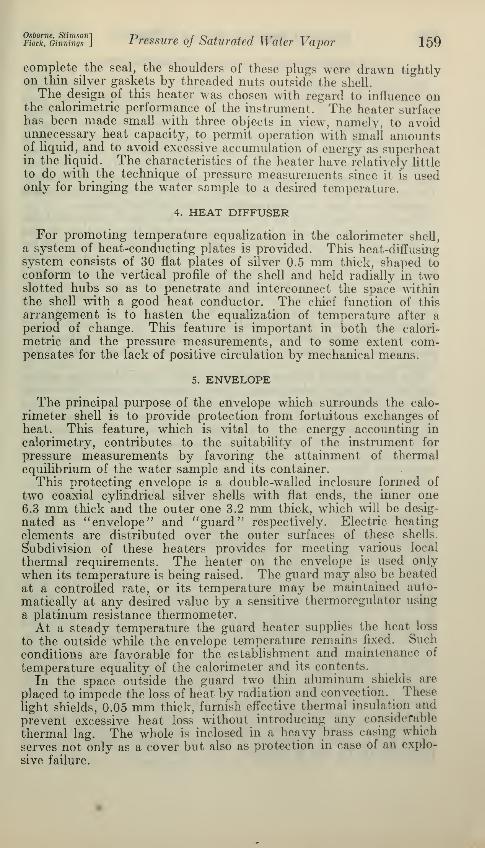
were relieved by annealing the completed thermometer at 660° C.Each thermometer is mounted in a cylindrical silver case which fits
the receptacle in the reference block. Figure 4 shows the construc-
tion of one of these thermometers.This type of thermometer winding has been described by C. H.
Meyers 3 and is particularly adapted to use where large size is objec-
tionable. The question as to whether a platinum winding of this
compact double-helical type will define the same temperature scale
between the fixed points as a winding of the customary strain-free
type, has been studied by making a direct comparison between one of
the thermometers of this apparatus and one of the earlier standard
thermometers of this laboratory. In the interval from 200° to 320° C,the maximum observed difference in indication was at 270° andamounted to 0.013° C, which is not more than that attributable to
the uncertainty of reproduction of the scale itself.
The two thermometers used (M-22 and M-26) were selected from
a group of eight by consideration of their characteristics and behavior
over a period of time. They were calibrated according to the specifi-
cations of the international temperature scale,4 which uses the fixed
points of ice, steam, and boiling sulphur as 0, 100, and 444.6°, respec-
tively. The thermometers were calibrated before and during the
progress of the pressure measurements and showed no significant
changes. The thermometer No. M-22, which was used in all the
experiments, had the constants R = 27.6037, i^ioo^ 38.5158, 5=1.496,
which were used in the Callendar formula given later for the tem-
» B. S. Jour. Research, vol. 9 (RP508), December, 1932.
• Burgess, G. K., B. S. Jour. Research, vol. 1 (RP22), p. C35, October, 1928.
152894—33 2
166 Bureau of Standards Journal of Research [Vol. 10
perature computation. The thermometer! No. M-26, which wasused only occasionally to check the other thermometer, had the
constants # = 27.7640, Rm = 38.6555, 6=1.496.The resistances of the thermometers are measured with a Mueller 5
bridge built by O. Wolff. The bridge coils are immersed in a ther-
mostated oil bath. A separate commutator switch permits the
observation of either thermometer. The bridge coils were recali-
brated several times during this investigation. A bridge current of
4.5 milliamperes was used both in the calibration and in the measure-ments of temperature. A galvanometer scale deflection of 1 mmcorresponded approximately to 0.0001 ohm, or about 0.001° C. for
the thermometers used.
III. EXPERIMENTAL PROCEDURE
The first step in a vapor pressure determination is the introduction
of a chosen amount of pure air-free water into the calorimeter.
The water used in these measurements was prepared from distilled
water by continuous low-pressure distillation in a special apparatus.The air was removed by pumping from the condenser a small fraction
of the vapor which carried with it all but a trace of the air dissolved in
the original water. This purification was found adequate to avoidany measurable partial pressure of air in the steam. A measuredsample of the purified water is transferred without contact with air
from the distilling apparatus to a special container, With this con-tainer attached to the evacuated calorimeter system, the water is
driven into the calorimeter shell by heating the c ontainer. Weighingthe container before and after this operation checks the amounttransferred to the calorimeter. This must be known in order to com-pute the correction for the height of the liquid at any time.
The calorimeter with its charge of water is next brought to thedesired temperature by adding heat electrically. At the same timethe envelope, guard, reference block, and connecting tubes are all
heated in a similar manner and at about the same rate. Their tem-peratures are finally adjusted by successive approximations while thecalorimeter with its contents approaches the desired uniform sta-
tionary temperature. As this chosen temperature is approached, theautomatic temperature control of the guard shell is put into operation.The behavior of the fluid in the calorimeter varies appreciably in
the temperature range covered by these experiments. At tempera-tures below 350° C, thermal gradients produced by heating the fluid,
diminish quickly, leaving only small persistent gradients. As the
critical region is approached, however, the gradients become larger.
The procedure used to hasten favorable conditions for observing pres-
sure at these high temperatures is first to heat the water above thedesired temperature and then to cool by lowering the envelopetemperature. This produces condensation on the upper calorimeterwalls, bathing them with liquid which tends to bring them nearer theeffective saturation temperature.As equilibrium is approached, successive approximations are made
to the adjustments necessary for a pressure measurement. Thecalorimeter pressure is balanced by the air pressure which in turn is
balanced by the load on the piston. If the temperature and pressure
» Mueller, B. S. Bull., vol. 13, p. 547, October, 1916.

Osborne, StimsonlFi™™GinSs\ Pressure of Saturated Water Vapor 167
in the calorimeter were stationary and the measuring apparatusadjusted to proper balance, the diaphragm of the pressure cell wouldbe at rest in its zero position, the two capillary indicators stationary,and the loaded rotating piston of the gage neither rising nor falling.
This ideal condition of absolute constancy is not necessary to a satis-
factory measurement. After close control and adjustment have beenobtained, they are held over a period of about two minutes while aseries of temperature readings is taken. The definitive value of theload is that at the mid-point of this period. The pressure observationincludes the balancing load on the piston, temperature of the piston,barometric pressure, and height of fluid columns in the capillary indi-
cators. The balancing load could always be determined to the nearestgram, and at low pressures it was possible to estimate fractions of agram. At the higher steam pressures it is unnecessary to determinethe load more closely than to 1 g in order to have the precision of thepressure measurement correspond with that of the temperature.For determining the effective saturation temperature, four suc-
cessive temperature readings are made at equal time intervals.
Each temperature reading consists of simultaneous observations of
resistance thermometer and thermoelements. The above method of
reading several successive temperatures is desirable for several reasons.
First, the 4-lead potential-thermal resistance thermometer requires at
least two observations to eliminate the lead resistance from themeasurement. Second, increasing the number of readings decreases
the accidental error of observation. Third, a regular schedule of
readings takes account of slight drift of temperatures. Fourth, the
schedule permits the observation of local temperatures during the
measurement.The best selection of thermoelements to determine the temperature
of the free surface of the water depends on the temperature distribu-
tion and the location of the liquid level in the calorimeter. In the
range of temperature below 350° C, the water and calorimeter reach
a steady state promptly. Below 200° C. this steady state was a
uniform temperature, as indicated by surveys. All five thermoele-
ments were therefore taken to indicate the saturation temperature
up to 200° C.Between 200° and 350° C, after the steady state was reached, the
bottom of the shell showed a small persistent depression of tempera-
ture and the top a small elevation due to inability to control the
surroundings perfectly. In this range the three intermediate ther-
moelements, Nos. 2, 3, and 4, were used.
Above 350° C. a difference in the behavior of the fluid was observed.
The steady state was reached more slowly and thermal gradients were
larger over the entire shell. The saturation temperature was esti-
mated from the indication of a single thermo-element located in the
vicinity of the liquid level in the calorimeter. If the quantity of water
in the calorimeter is checked as previously described, the location of
the liquid level is reliably known at temperatures below 370° C.
Near the critical region, a comparatively small difference in the water
sample determines whether saturated vapor, superheated vapor, or
compressed liquid is present. Experiments were therefore made to
indicate the state of the water in the calorimeter. These experiments
started with the calorimeter supposed to be full of liquid water. After
the pressure was observed, a chosen small amount of liquid was with-
168 Bureau oj Standards Journal oj Research [Vohio
drawn and the pressure again observed. This procedure was repeateduntil the observed pressure, when reduced to a given temperature,showed a constant value indicating existence of the saturation state.
During the progress of the vapor-pressure measurements, two typesof experiments were made to prove the absence of an appreciableamount of permanent gas in the calorimeter. In the first type, pres-
sures were measured before and after the withdrawal of liquid, whichincreased the vapor space in the calorimeter. In the second type, the
presence of gas in the calorimeter was tested by a McLeod gage after
removal of the liquid. These tests gave no indication of enough gasto affect the vapor-pressure results.
IV. RESULTS OF MEASUREMENTS
The results of the entire series of measurements have been assembledin Table 1, which includes each measured temperature, reduced to
degrees of the international temperature scale of 1927 6 and the cor-
responding measured pressure reduced to international standardatmospheres.7 This table also contains the reduction of the observedpressures to values corresponding to even temperatures to permitcomparison of the individual determinations and to facilitate theformulation of the entire group of results.
Each measured temperature is computed from the observed data,consisting of four readings of the bridge when balanced with the plati-
num resistance thermometer in circuit, and the four simultaneousreadings of the potentiometer when balanced against the thermo-elements, as described above in Section III, Experimental Procedure.Each measured pressure is computed from the following observed
quantities: The load on the piston gage, temperature of gage, position
of water meniscus and oil meniscus, amount of water in the calori-
meter, and barometer reading, including its temperature.The auxiliary data used in these reductions include the densities of
water and of oil, value of gravity at the Bureau of Standards, therelative elevation of gage and barometer from the gravity bench mark,the results of calibrations of the bridge, resistance thermometers,thermoelements, and the piston gage with its connecting lines andweights.
The mean of the four bridge readings corrected for the bridge cali-
bration gives the resistance of the platinum thermometer (Re ) at themean temperature of the series. The temperature, 0, is computedfrom this resistance by use of the Callendar formula
0=100 (Re-R )I(Rm- i?o + 0.01 0(0.01 0-1) 5
The constants R0) Rm , and 8 are determined by the calibration pre-viously described.The mean of the four thermoelement observations is reduced from
microvolts to degrees temperature difference by use of the calibrationfactor determined as previously described. By combining this meantemperature difference between the water and the reference block
• Burgess, O. K., B. S. Jour. Research, (RP 22) p. 635, October, 1928.7 Standard atmospheric pressure is denned as the pressure due to a column of mercury 760 mm high,
having a mass of 13.5951 g/cma, subject to a gravitational acceleration of 980.665 cm/sec.' and is equal to1,013,250 dynes/cm», B. S. Jour. Research, October, 1928, p. 637.

Otborne, Stimsori]
Fiock, Oinnings JPressure of Saturated Water Vapor 169
and the mean temperature of the block as determined by the thermom-eter, the temperature of the water, dw , is obtained.The pressure observation, made at the middle of the series of
temperature readings, corresponds with the water temperaturedetermined as above. In reducing the pressure observation, theeffective weight of the entire load supported by the oil acting on theeffective piston area was computed as the sum of the masses of theweights, weight carrier, and the piston, corrected for calibration andair buoyancy. From this total mass the resultant pressure wascomputed by use of the value of gravity at this laboratory (980.09cm/sec. 2
) relative to the standard value of gravity (980.665 cm/sec. 2)
and the effective piston area, corrected for the effect of thermalexpansion. To this component of pressure due to the load was addedthe observed barometric pressure corrected for temperature, differ-
ence in level, and for gravity, thus giving the total pressure at thebottom of the piston. From this pressure at the gage, the pressureat the level of the liquid in the calorimeter was found by applyingthe following corrections for the intermediate fluid columns: Theoil column between the piston and the oil meniscus, the air columnbetween oil and water, the water column between the water meniscusand the water level in the calorimeter, and the correction for thediaphragm position determined by the calibration at atmosphericpressure. The pressure contributed by the liquid water column in
the calorimeter was calculated from the mass of water in the calori-
meter, the dimensions of the calorimeter and the specific volumes of
vapor and liquid water determined by Keyes and Smith. 8
The total correction for fluid columns in the transmission line did
not exceed 0.04 atmosphere and was estimated to 0.0001 atmosphere.The accuracy of this estimation may have limited the precision
attainable at the lowest pressures measured. At the higher pressures,
it was of less importance in comparison with several other factors.
Table 1.
—
Observed pressure of saturated water vapor
Observed quantities
Reductionto eventemper-ature
Vaporpressure at
eventemper-atureP
Date Temper-ature
PressureP.
ResidualP-Pm
July 20, 1932
°C. (Inl.)
f110. 027110. 018
1 110.003
I 110.019
f 110.011109. 994
1 110.008
I110. 027
i
1.41461. 41521. 41491.41561.41481.41381. 41461.4156
standard atm-0.0013-.0009-.0001-.0009-.0005+.0003-.0004-.0013
^spheres (Int
1.41331.41431. 41481.41471.41431.4141
1.41421.4143
)
-0. 0010.0000
+.0005+.0004
.0000-.0002
July 21, 1932
.0000
Even temperature 110°. Mean value of pressure at 110 =P.= 1.4143 atm.
July 20, 1932.
July 21, 1932.
f119. 975 1. 9579 +0. 0015 1.
9 ',94
119.991 1.9587 +.0006 1. 9593
i 119.981 1.9587 +.0012 1. 9599
120. 010 1.9608 -.0006 1.9602
f 119.982 1.9590 +.0011 1.9601
119.956 1.9564 +.0027 I". 9591
i 120. 004 1.9604 -.0003 1.9601
I 119.988 1.9596 +.0007 1.9603
Even temperature 120°. Mean value of pressure at 120° = P„= 1.9598 atm.
•Mechanical Engineering, vol. 53, No. 2 ,p. 133, 1931.
-0.0004-.0005+.0001+.0004+.0003-.0007+.0003+.0005

170 Bureau oj Standards Journal of Research [Vol. w
Table 1.
—
Observed pressure of saturated water vapor—Continued
Date
Observed quantities
Temper-ature
PressurePw
Reductionto eventemper-ature
Vaporpressure at
eventemper-atureP
ResidualP-Pm
April 2, 1932.
April 5, 1932.
April 7, 1932April 8, 1932
July 2, 1932.
July 7, 1932.
July 21, 1932
Standard atmospheres (Int.)
2. 6624 +0. 0028 2. 66522. 6635 +. 0028 2. 66632. 6636 +. 0028 2. 66642. 6656 -. 0011 2. 66452.6644 -.0006 2.66382. 6641 +. 0003 2. 66442. 6652 +. 0007 2. 66592. 6636 +. 0023 2. 66592. 6660 . 0000 2. 66602. 6692 -. 0037 2. 68552. 6665 +. 0002 2. 66672. 6649 +. 0019 2. 66682. 6670 -. 0002 2. 66682. 6686 -. 0018 2. 6668
Even temperature 130° Mean value of pressure at 130°=Pm= 2.6658 atm.
April 2, 1932.
April 5, 1932.April 7, 1932.April 8, 1932.
July 2, 1932..
July 7, 1932..
July 21, 1932.
140.
140.
140.
140.
139.
139.
139.
139.
140.
140.
139.
139.
140.
3. 60273. 60283. 60283. 56823. 56143. 56253. 56533. 56343. 56753. 56653. 56543. 56623. 5694
-0. 0373-.0374-. 0374-.0023+. 0020+. 0017
+. 0016+. 0032-. 0005-.0004+. 0025+ 0012-.0021
3. 56543. 56543. 56543. 5659
563456425669566656705661567956745673
Even temperature 140°. Mean value of pressure at 140°=Pm =3.5661 atm.
March 25, 1932.March 28, 1932.March 29, 1932.March 30, 1932.April 1, 1932 ...
April 7, 1932...April 8, 1932...July 7, 1932....
July 21, 1932.
149. 879149. 911149. 868150. 032149. 998149. 984150. 004150. 035149. 985150; 004150. 025
4. 68024. 68494. 67894. 70184. 69704. 69224. 69644. 70174. 69714. 69944. 7019
f0. 0152 4. 6954+.0112 4. 6961+. 0166 4. 6955-. 0040 4. 6978+.0002 4. 6972+. 0020 4. 6942-. 0005 4. 6959-. 0044 4. 6973+. 0019 4.6990-.0005 4. 6989-. 0031
Even temperature 150°. Mean value of pressure at 150°=Pm =4.6969 atm.
April 2, 1932-
April 7, 1932.April 8, 1932.
July 2, 1932..
July 7, 1932..
July 21, 1932.
160. 067160. 068160. 068160. 027159. 990160.016159. 999160. 022160.016159. 965159. 978159.997
6.11016. 11026.11026. 10286. 09726. 10316. 09966. 10366. 10236. 09566. 09506. 1008
-0. 0104-. 0106-. 0106-. 0042+.0016-.0025+. 0002-. 0034-.0025+. 0054+.0034+.0005
.0997
6. 09886.10066. 09986. 10026. 09986. 10106. 09846.1013
Even temperature 160°. Mean value of pressure at 160° =P B1 =6.0998 atm.
April 2, 1932
April 5, 1932April 7, 1932April 8, 1932.
July 2, 1932.
July 7, 1932.
July 21, 1932
169. 994169. 993169. 994170. 016169.993169. 992169.991169.981169. 996170.002169. 978169.996170.014
7. 81827. 81827. 81827. 81837.81477. 81407.81597. 81407. 81687. 81747. 81487. 81827. 8216
+0.0011+. 0013+.0011-.0030+. 0013+. 0015+.0017+. 0036+.0008-.0004+.0042+.0008-.0026
7. 81937. 81957. 81937. 81537. 81607. 81557. 81767. 81767. 81767. 81707. 81907. 81907. 8190
Even temperature 170°. Mean value of pressure at 170°=Pm= 7.8178 atm.

Osborne, StimsonFiock, Oinnings ] Pressure oj Saturated Water Vapor 171
Table 1.
—
Observed pressure of saturated water vapor—Continued
Observed quantities
Reductionto eventemper-ature
Vaporpressure at
eventemper-atureP
DateTemper-ature
PressureP„
ResidualP-Pm
April 2, 1932
°C. (Int.)
{ 180. 024
{ 180. 022
I 180. 022180. 014180. 001179. 999
( 179. 982
{ 179. 969
I 179. 996
Standard atm9. 9023 -0. 00559.9011 -.00509.9017 -.00509.8990 -.00329. 8966 -. 00029. 8918 +. 00029. 8926 +. 00419. 8887 +. 00719. 8953 + . 0009
^spheres (Int
9. 89689. 89619. 89679. 89589.89649. 89209. 89679. 89589. 8962
)
+0. 0010+.0003+.0009.0000
+.0006-.0038+.0005
0000
April 5, 1932April 7, 1932April 8, 1932
July 7, 1932
+.0004
Even temperature 180°. Mean value of pressure at 180°=Pm =9. 8958 atm.
April 2, 1932
April 5, 1932April 7, 1932April 8, 1932
July 7, 1932.
190. 001190. 002190. 002190. 005190. 010190. 010190. 010189. 998190. 012
12. 391312. 390412. 390512. 389012. 390812. 389812. 390812. 387112. 3918
-0. 0003-.0005-.0005-.0014-.0027-.0027-.0027+.0005-.0033
12. 391012. 389912. 390012. 387612. 388112. 387112. 388112. 387612. 3885
Even temperature 190°. Mean value of pressure at 190°=Pm =12. 3887 atm.
March 25March 28March 29March 30,
April 1, 1932April 7, 1932April 8, 1932
July 7, 1932.
1932.1932.
1932.
1932.
200. 141
199. 957200. 037199. 700199. 935199. 990199. 712199. 996199. 976199. 987
15. 392015. 333215. 357615. 253015. 326415. 344315. 253515. 346315. 339515. 3440
-0. 0453+. 0138-.0119+. 0963+. 0209+.0032+.0924+.0013+. 0077+.0042
15. 346715. 347015. 345715. 349315. 347315. 347515. 345915. 347615. 347215. 3482
Even temperature 200°. Mean value of pressure at 200°=Pm= 15.3472 atm.
April 4, 1932..April 5,1932..April 7, 1932..April 8, 1932..April 29, 1932.
July 7, 1932—
209. 991210. 026210.006210. 030209. 979209. 979209. 957209. 994
18. 825618. 839318. 831418. 842418. 824518. 821318. 813318. 8277
+0. 0034-.0098-. 0023-.0113+. 0079+. 0079+. 0162+.0023
18. 829018. 829518. 829118.831118. 832418. 829218. 829518. 8300
Even temperature 210°. Mean value of pressure at 210°=Pm= 18.8300 atm.
April 4, 1932..April5, 1932..April7, 1932..April8, 1932.-April 29, 1932.
July 7, 1932...
219. 998220. 002220. 003220. 013219. 993219. 999219. 977219. 996
22. 896022. 896322. 896022. 900622. 894822. 896322. 886722. 8960
+0. 0009-.0009-. 0013-.0057+.0031+.0004+.0101+.0018
22. 896922. 895422. 894722. 894922. 897922. 89(57
22. 896822. 8978
Even temperature 220°. Mean value of pressure at 220° =Pm= 22.8964 atm.
April 4, 1932. .
April 5, 1932.
.
April 7, 1932..April 8, 1932..April 29, 1932.
July 7, 1932...
Even temperature 230°
April 4, 1932..April 5, 1932..April7, 1932.
.
April 8, 1932..April 29, 1932.
July 8, 1932—
230. 007 27. 6156
230. 019 27. 6187
230. 015 27. 6203
230. 010 27. 6137
230. 006 27. 6160
229. 986 27. 6055
229. 951 27. 5883
229.999 27. 6115
value of pressure at 2
240. 014 33. 0550240. 060 33. 0706
240. 015 15:5. 0171
240. 021 33. 0499
240. 026 33. 0575
239. 976 33. 0307
239. 955 33.0188
-0. 0036-.009(5-.0076-.0051-.0030+.0071+.0248+.0005
-0.0081-.0349-.0087-.0122-.0151+. 0139+.0261
27.612027. 0091
27 B13227.608827. 613027.613627.1,1:51
27. 6120
33. 0409153. 03573:5. 038733. 0377
33. 0424
33.044633. 0449
+0. 0023+.0012+.0013-.0011-.0006-.0016-.0006-.0011-.0002
-0.0005-.0002-.0015+.0021+.0001+.0003-.0013+.0004.0000
+.0010
-0.0010.-. 0005-.0009+.0011+. 0024-.0008-.0005.0000
+0.0005-.0010-.0017-.0015+.0015+.0003+.0004+.0014
+0.0003-.002(5
+.0015-.0031+.0013+.0009+.0014+.0003
+0. 0053-.0059-.0029-.0039+.0008+.0030+.0033
Even temperature 240°. Mean value of pressure at 240° -P- -33.0146 atm.
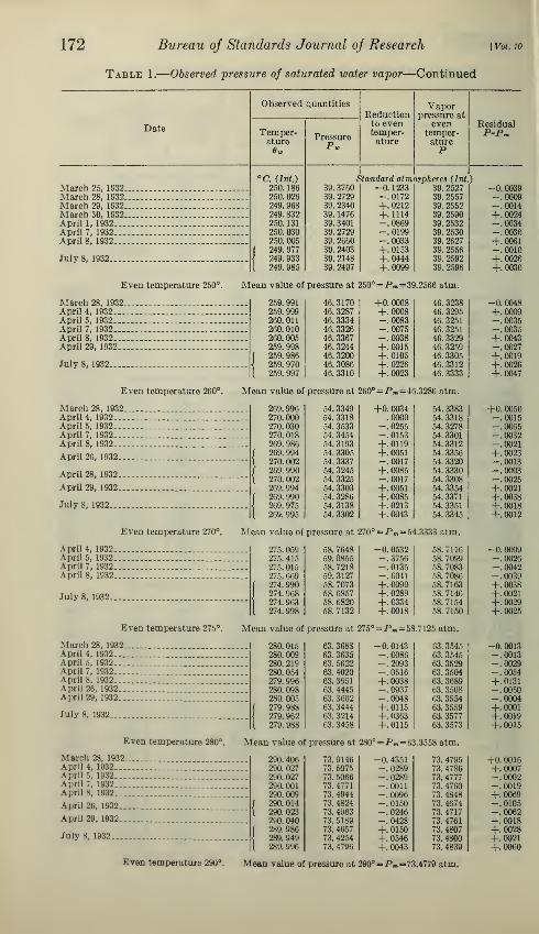
172 Bureau of Standards Journal of Research [Vol w
Table 1.
—
Observed pressure of saturated water vapor—Continued
Observed quantities
Reductionto eventemper-ature
Vaporpressure at
eventemper-atureP
Date Temper-ature6w
PressureP»
ResidualP-Pn
March 25, 1932.
°C. (Int.)
250. 186250. 026249. 968249. 832250. 131250. 030250. 005
( 249. 977
\ 249. 933
1 249. 985
Standard atmospheres (Int
39. 3760 -0. 1233 39. 252739. 2729 -. 0172 39. 255739. 2340 +. 0212 39. 255239.1476 +.1114 39.259039. 3401 -. 0869 39. 253239. 2729 -. 0199 39. 253039. 2660 -. 0033 39. 262739. 2403 +. 0153 39. 255639. 2148 +. 0444 39. 259239. 2497 +. 0099 39. 2596
)
-0.0039March 28, 1932 -.0009March 29, 1932 -.0014March 30, 1932 +.0024April 1, 1932 -.0034April 7, 1932 -.0036April 8, 1932 +.0061
July 8, 1932
-.0010+.0026+.0030
Even temperature 250°. Mean value of pressure at 250°=Pm =39.2566 atm.
March 28, 1932.April 4, 1932. ..
April 5, 1932...April 7, 1932. ..
April 8, 1932...April 29, 1932..
July 8, 1932....
259. 991259. 999260. 011260. 010260. 005259. 998259. 986259. 970259. 997
46. 317046. 328746. 333446. 332646. 336746. 324446. 320046. 308646. 3310
+0. 0068+.0008-.0083-.0075-. 0038+.0015+. 0105+. 0226+.0023
46. 323846. 329546. 325146. 325146. 332946. 325946. 330546. 331246. 3333
Even temperature 260°. Mean value of pressure at 260°=Pm =46.3286 atm.
March 28, 1932.April 4, 1932...April 5, 1932...April 7, 1932. „April 8, 1932...
April 26, 1932..
April 28, 1932. .
April 29, 1932..
July 8, 1932-..
270. 000270. 030270. 018269. 986269. 994270. 002269. 990270. 002269. 994269. 990269. 975269. 995
54. 334954. 331854. 353354. 345454. 319354. 330554. 333754. 324554. 332554. 330354. 328654. 313854. 3302
+0. 0034.0000
-. 0255-. 0153+.0119+.0051-.0017+.0085-.0017+.0051+.0085+. 0213+.0043
54. 338354. 331854. 327854. 330154. 331254. 335654. 332054. 333054. 330854. 335454. 337154. 335154. 3345
Even temperature 270°. Mean value of pressure at 270°=Pm= 54.3333 atm.
April 4, 1932.April 5, 1932.April 7, 1932.April 8, 1932.
July 8, 1932.
275. 059275. 415275. 015275. 669274. 990274. 968274. 963274. 998
58. 764859. 085558. 721859.312758. 707358. 685758. 682058. 7132
-0. 0532-. 3756-.0135-. 6041+.0090+.0289+.0334+.0018
58. 711658. 709958. 708358. 708658. 716358. 714658. 715458. 7150
Even temperature 275°. Mean value of pressure at 275°=P«=58.7125 atm.
March 28, 1932.April 4, 1932...April 5, 1932...April 7, 1932...April 8, 1932...April 26, 1932..April 29, 1932..
July 8, 1932
280. 015280.009280. 219280. 054279. 996280. 098280. 005279. 988279. 962279. 988
63. 368863. 363563. 562263.402063. 365163. 444563. 360263. 344463. 321463. 3458
-0.0143-.0086-.2093-. 0516+.0038-.0937-.0048+.0115+.0363+.0115
63. 354563. 354503. 352963. 350463. 368963. 350863. 355463. 355963. 357763. 3573
Even temperature 280°. Mean value of pressure at 280°=Pm = 63.3558 atm.
Marcli 28, 1932.April 4, 1932...April 5, 1932...April 7, 1932...April 8, 1932...
April 26, 1932..
April 29, 1932..
July 8, 1932....
290. 406290.027290. 027290.001290.009290. 014290. 023290. 040289.986289. 949289. 996
73. 914673. 507573. 506673. 477173. 494473.482473. 496373. 518973. 465773. 425473. 4796
-0.0048+.0009-.0035-.0035+.0043-.0027+.0019+.0026+.0047
+0. 0050-.0015-.0065-.0032-.0021+.0023-.0013-.0003-.0025+.0021+.0038+.0018+.0012
-0.0009-.0026-.0042-.0039+.0038+.0021+.0029+.0025
-0. 0013-.0013-.0029-.0054+. 0131-.0050-.0004+.0001+.0019+.0015
-0. 4351 73. 4795 +0. 0016-.0289 73. 4786 +.0007-.0289 73. 4777 -.0002-.0011 73. 4760 -.0019-.0096 73. 4848 +.0069-. 0150 73. 4674 -.0105-. 0246 73. 4717 -.0062-.0428 73. 4761 -.0018+. 0150 73.4807 +.0028+. 0546 73.4800 +.0021+.0043 73. 4839 +.0060
Even temperature 290°. Mean value of pressure at 290°-P«- 73.4779 atm.

^GinnZT] Pressure oj Saturated Water Vapor 173
Table 1.
—
Observed pressure of saturated water vapor—Continued
Date
March 25, 1932March 28, 1932March 29, 1932March 30, 1932April 1, 1932...April 7, 1932...Aprils, 1932...
June 30, 1932...
July 1, 1932....
July 8, 1932....
Observed quantities
Temper-ature
'C. (Int.)
300.129300.005299. 970299. 953300.048300. 047300. 025299.609299. 954299.813299. 654300.009299.974299. 973300. 012
Pressure
Reductionto eventemper-ature
Vaporpressure at
evoutemper-atureP
ResidualP-Pm
84. 946484. 807584. 759284. 747584. 857884. 849284. 823284. 324484.744184. 576684.380384.809584. 767184. 766284.8111
Standard atmospheres (Int.)-0. 1546-.0060+. 0358+. 0561-.0573-.0561-. 0299+.4665+. 0549+.2234+.4128-. 0107+.0311+.0322-. 0143
84. 791884. 801584. 79.
r,0
84. 803684.800584. 7931
84. 793384.790984.799084.800084. 7931
84.798884. 798284. 798484.7968
Even temperature 300°. Mean value of pressure at 300° =Pm =84.7969 atm.
March 28, 1932.
April 4, 1932...April5, 1932...April 7, 1932...April8, 1932...
April 25, 1932.
April 29, 1932.
July 1, 1932...
July 11, 1932.
310. 019310. 039310. 036309. 980309.902310. 015310. 015310. 017310. 030309. 975309.993309.973309. 989
97. 429897. 461597. 450397. 382297. 281697. 425997. 424697. 426497. 436197. 368597.400697. 375397. 3949
-0. 0253-. 0518-.0478+. 0266+.1302-. 0199-.0199-.0226-. 0399
+. 0332+.0093+. 0359+. 0146
Even temperature 310°. Mean value of pressure at 310° = Pm=97.4062 atm.
April 4, 1932...
April 5, 1932-April 7, 1932..April 8, 1932..April 29, 1932.
July 1, 1932...
July 11, 1932.
320. 070320. 032320. 045320.020320. 017320.007320.007319. 957320.012320. 017319, 994320. 003
111. 524111.473111. 493111.460111.447111.426111. 422111. 333111.418111.446111.415111.425
-0. 103-.047
-.025-.010-.010+.063-.018-.025+.009-.004
111.421111.426111.427111.430111.422111.416111.412111. 396111.400111.421111.424111.421
Even temperature 320°
April 4, 1932.
April 5, 1932.April 7, 1932.April 8, 1932.
July 1, 1932..
July 11, 1932.
Even temperature 325c
April 4, 1932..April 5, 1932..April 7, 1932..April 8, 1932..
April 26, 1932.
April 29, 1932.
July 11, 1932..
Mean value of pressure at 320°=P„=111.418 atm.
118.994118. 992118.988118.992118.970118.974118.996118.991118.992
$8 atm.
126. 961
13&.964126.968136.988136.067126.954126.950126. 960126.960126. 959126.953126.963
325.025 119.033 -0. 039
325. 033 119.043 -.051325.004 118.994 -.006325.004 118.998 -.006324.968 118.920 +.050324.923 118.854 +.120325.005 119.004 -.008324.997 119. 986 +.005325. 038 119.052 -.000
value o pressure at 325°-P.-ll
330.020 126.994 -0. 033
330. 010 126.980 -.016330.009 126. 983 -.015
330.012 126.988 -.020330. 020 126.990 -.033
330. 033 127.008 -.054330.038 127. 012 -.062330. 043 127. 030 -.070
330. 026 127.002 -.042330.014 127. 982 -.023330. 032 127.005 -.052330.025 127.004 -.041
-0. 0051
+.0046-.0019+.0067+.0036-.0038-.0036-.0060+.0021+.0031-.0038+.0019+.0013+.0015-.0001
97.4045 -0. 001797.4097 +.003597.4025 -.003797.4088 +.002697. 4118 +. 005697.4060 -.000297.4047 -.001597.4038 -.002497. 3962 -.010097. 4017 -.003597.4099 +.003797.4112 +.005097.4095 +.0033
+0.003+.008+.009+.012+.004-.002-.006-.022-.018+.003+.006+.003
+0.006+.004.000
+.004-.018-.014
008003
+++.004
40.001+.004+.008+.008-.003-.008-.010.000.000
-.001-.007+.003
Even temperature 330°. Mean value of pressure at 330°=P.« 126.960 atm.

174 Bureau of Standards Journal of Research [Vol. w
Table 1.
—
Observed pressure of saturated water vapor—Continued
Date
Observed quantities
Temper-ature
PressureP„
Reductionto eventemper-ature
Vaporpressure at
eventemper-atureP
April 4, 1932..
April 5, 1932.April 7, 1932.April 8, 1932.
April 28, 1932
April 29, 1932
July 11, 1932.
144. 229144. 243144. 231144. 197144. 208144. 204144. 213144. 216144.211144. 161
144. 222
Standard atmospheres (Int!)
-0. 063-.072-.074-.027-.038-.045-.051-.047-.042+.011-.051
144.166144. 171
144.157144.170144.170144. 159144. 162144. 169144169144. 172144.171
Even temperature 340°. Mean value of pressure at 340°=Pm =144.167 atm.
March 29, 1932.March 29, 1932.
March 30, 1932.
April 1, 1932...April 5, 1932...April 7, 1932...
April 8, 1932...
April 27, 1932..
July 11, 1932.
July 12, 1932.
July 12, 1932.
July 13, 1932.
349. 998349. 996349. 989350. 110350. 089350. 057349. 999350. 026350. 043350. 060350. 001350. 018350. 027350. 009350. 020350. 025349. 995350. 006
163. 208163. 209163. 183163. 421163. 382163. 324163. 198163. 254163. 282163. 332163. 215163. 225163. 262163. 218163. 246163. 254163. 197163. 214
|
+. 0. 004+.008+ 022-.220-.178-.114+ 002-.052-.086-.120-.002-.036-.054-.018-.040-.050+.010-.012
163. 212163. 217163. 205163. 201163. 204163. 210163.200163. 202163. 196163. 212163. 213163. 189
163. 208163.200163. 206163.204163. 207163. 202
Even temperature 350°. Mean value of pressure at 350°=Pm= 163.205 atm.
355. 037355. 006355. 022354. 988354. 966355. 013
173. 552173. 475173. 521173. 449173. 402173. 507
-. 0. 078-.013-.046+.025+.072-.027
173. 474173. 462173. 475173. 474173. 474173. 480
Even temperature 355°. Mean value of pressure at 355°=Pm= 173.473 atm.
April 29, 1932.
July 12, 1932..
July 13, 1932.
July 12, 1932.
July 13, 1932.
July 12, 1932.
July 13, 1932.
Even temperature 360c
360. 008 184. 311 -0. 018 184. 293f 360. 029 184. 365 -.064 184 301
\ 359. 996 184. 291 + 009 184. 300
I 360. 004 184. 308 -.009 184 299359. 976 184. 241 +.053 184. 294
{ 359. 959 184.208 + 091 184 299
{ 359. 996 181285 + 009 184 294
iean value of pressure at 360°=Pm= U54.297 atm.
f 361. 993 188. 770 +0. 016 188. 786361. 990 188. 765 + 023 188. 788361. 973 188. 729 +.061 188. 790362. 007 188. 803 -. 016 188. 787361. 981 188. 741 + 043 188. 784
\ 361. 965 188. 708 + 079 188. 787
I 361. 992 188. 770 +.018 188.788
Even temperature 362° Mean value of pressure at 362° =Pm= 188.787 atm.
363. 996363. 978364. 009363. 972363. 958363. 981
193. 367193. 323193. 401193. 314193. 282193. 338
+0.009+.051-.021+ 065+ 097+.044
193. 376193. 374193. 380193. 379193. 379193. 382
Even temperature 364° Mean value of pressure at 364°=Pm =193.378 atm.

Osborne, StimsonFiock, Ginnings Pressure of Saturated Water Vapor 175
Table 1.
—
Observed pressure of saturated water vapor—Continued.
Date
July 12, 1932.
July 13, 1932.
July 13, 1932.
July 14, 1932.
Apr. 29 1932.
Observed quantities
Temper-ature
PressureP«
>C. (Int.)
366. 019365. 992366. 032366. 034366. 022365. 951
365, 938366. 004
Reductionto eventemper-ature
Yuporpressure at
eventemper-atureP
ResidualP-Pm
198. 110198. 038198. 139
198. 143198. 119197. 949197. 917198. 078
Standard atmospheres (Int.)
-0. 045+.019-.076-.081-.052+.116+.147-.009
His. 065198. 057198. 063198. 062198. 067198. 065198. 064198. 069
Even temperature 366° Mean value of pressure at Pm= 198.064 atm.
368. 009367. 988368. 030368. 047368. 040368. 018
202. 876202, 831202. 938202. 972202. 947202. 899
-0. 022+.029-.073-.114-.097-.044
202. 854202. 860202. 865202. 858202. 850202. 855
Even temperature 368° . Mean value of pressure at 368°=Pm= 202. 857 atm
.
July 13, 1932.
July 14, 1932.
370. 014370. 009370. 010370. 020370. 035369. 959370. 017370. 034370. 013370. 056370. 041370. 012370. 006369. 983370. 016370. 010369. 986370. 017370. 001
207. 801207. 788207. 792207. 820207. 857207. 667207. 829207. 862207. 810207. 924207. 870207. 804207. 795207. 723207. 812207. 789207. 726207. 808207. 766
-0. 035-.022-.025-.049-.087+.101-.042-.084-.032-.138-.101-.030-.015+.042-.040-.025+.035-.042-.002
207. 766207. 766207. 767207. 771207. 770207. 768207. 787207. 778207. 778207. 786207. 769207. 774207. 780207.765207. 772207. 764207. 761
207. 766207. 764
Even temperature 370°. Mean value of pressure at 370° =Pm= 207.771 atm.
July 14, 1932.
July 15, 1932.
July 15, 1932.
July 22, 1932.
370.952370.966371, 091
371, 082371. 046371. 038371. 015371. 011
370. 953370. 914370. 900370.892
Even temperature 371°. Mean value of pressure at 371'
371. 993 212. 780
372. 004 212. 806
372. 027 212. 866
372. 014 212. 831
372. 020 212. 848
372. 016 212. 846
372.070 212.966
372. 072 213. 074
372. 098 213. 033
210. 147
201. 182210.511210. 480210. 389210. 360210. 315210. 297210. 149210. 047210. 022209. 987
210. 267210. 267210. 284210. 275
210. 274210. 265210. 278210. 270210. 266210. 262210. 272210. 257
=Pm =210.270atm.
f-0.120+.085-.227-.205-.115-.095-. 037-.027+.117+.215+.250+. 270
+0. 018-.010-.068-.035-.051-.040-.177-.182-.248
212. 798212.796212. 798212. 796212. 797
212. 806212. 789212.792212. 785
Even temperature 372°. Mean value of
July 15, 1932.
July 22, 1932.
373. 012
373. 012
373. 003373. 005372. 987372. 983372. 974372. 974
372. 996373. 059373. 029373. 008
pressure at 372
215. 393215.391215. 373215. 367
215. 330215. 318215. 294215.299215. 361215.515215. 447
215. 381
° =Pm =212.795 atm.
-o. (m-.031-.008-. 013
+. 033+.043+.066+.066+.010-.151-.074-.020
215. 362215. 360215.365215. 354215. 363215.361215. 300215. 365215.371215. 364215. 373215. 361
+0.001-.007-.001-.002+.003+.001
.000+.005
-0. 003+.003+.008+.001-.007-.002
-0.005-.005-.004.000
-.001-.003+ 016+.007+.007+.015-.002+.003+.009-.006+.001-.007-.010-.005-.007
-0. 003-.003+.014+.005+.004-.005+.008.000
-.004-.008+.002-.013
+0.003+.001+.003+.001+.002+.011-.006-.003-.010
-0.001-.003+.002-.009.000
-.002-.003+.002+.008+.001+. 010-.002
Even temperature 373° Mean value of pressure at 373° =P«= 215.363 atm.

176 Bureau of Standards Journal of Research [Vol. 10
Table 1.
—
Observed pressure of saturated water vapor—Continued
Date
Observed quantities
Temper-ature
Pressure
Reductionto eventemper-ature
Vaporpressure at
eventemper-atureP
Residua]P-Pm
July 22, 1932.
July 25, 1932.
Standard atmospheres (Int.)
Even temperature 374°
>C. (Int.)
374. 001373. 998373. 992373. 999373. 978373. 957374. 039373. 971373. 948374. 037374. 052374.044374. 069
Mean value of pressure at 374°=Pm= 217.985 atm.
217. 985 -0.003 217.982217. 980 +.005 217. 985217. 956 +.021 217. 977217. 971 +.003 217. 974217. 913 +.057 217. 970217. 859 +.111 217. 970218. 091 -.101 217. 990217. 912 +.078 217. 990217. 855 +.134 217. 989218. 090 -.096 217. 994218. 135 -.134 218. 001218. 106 -.114 217. 992218. 169 -.178 217. 991
-0.003.000
-.008-.011-.015-.015+.005+.005+.004+.009+.016+.007+.006
V. FORMULATION OF RESULTS
Proceeding with the mean values of vapor pressure correspondingto even temperatures assembled in Table 1 as described above, the
next step was to express the aggregate result of the entire series by
to
9
8sCffect of .001 aim. error
Temperature in 'C.
Figure 5.
—
Deviation of mean observed pressures from the Bureau of Stand-ards formulation
means of a formula in order to smooth out irregularities caused byaccidental errors of observation, and to provide a trustworthy methodfor interpolating intermediate values and for obtaining the derivative.The results of this formulation are given in Table 2. The constantsof the empirical equation were determined by the method of leastsquares. Since the pressure at the 100° point is fixed by definition,the formula was made to give the value of exactly 1 atmosphere atthis point. It was found necessary to apply the formula over twooverlapping temperature ranges in order to secure a satisfactory fit.

StaST&SST] Pressure of Saturated Water Vapor 177
The agreement of the formula with observation is shown by thedifferences in columns 4 and 5 and graphically in Figure 5. 'Sincethese differences in no case exceed the amount which experimentalerrors might cause, the formula is taken as a reliable representation ofthe aggregate results of the complete series of measurements. Thisformulation is the basis of a mutually consistent group of tablessuitable for use as actual working tables. They are expressed invarious appropriate units and arranged in convenient form to providefor intercomparison of current steam tables. The number of signifi-
cant figures retained may be more than corresponds to the absoluteaccuracy of measurement, yet was determined by considerations ofconsistency and precision of formulation, calculation, conversion ofunits, and comparisons. The derivative is included because this
factor is important for making thermodynamic correlations and for
interpolating intermediate values.
For the units which involve the value of the intensity of gravitythe internationally accepted value of 980.665 cm/sec. 2 or its equiv-alent in the English system (32.174 ft. /sec.
2) has been used.
Obviously it would be undesirable to complicate the tabulationfurther by taking into account the difference of gravity in different
localities. It may be regarded as unfortunate that existing engineer-ing practice still retains pressure units which involve local values of
gravity, particularly since the difference is usually so small that thechange to standard gravity could be made painlessly.
It should not be overlooked that the temperatures given in this
group of tables are expressed either on the international centigrade
scale or on the Fahrenheit scale derived from it. For correlations
involving the second law of thermodynamics, the departure of this
temperature scale from the absolute or thermodynamic scale mustbe taken into account if it should be found to be significant.
Table 3 contains the values of the pressure of saturated watervapor and the derivative with respect to temperature at each ° C.
from 100° to 374°. Values are given in each of the three units of
pressure which are ordinarily used with the centigrade scale. Thestandard atmosphere is the standard international unit which has
been used as the basis of reduction of the measurements. Thecentibar is a decimal subdivision of an internationally recognized
unit of pressure.9 This unit possesses several advantages for use as a
practical working standard. It is derived directly from the funda-
mental units of length, mass, and time independently of the properties
of any substance or of the intensity of gravity. It may therefore be
used in thermodynamic calculations with other current cgs units
without requiring a conversion factor, a property possessed by no
system of thermodynamic units used in current steam tables. This
unit is of convenient size for practical use and has a convenient and
unequivocal name, which is a unique combination.
« The bar, equal to 10« dynes/cm* was approved as a unit of pressure by the International Meteorological
Commission, Rome, 1913.

178 Bureau of Standards Journal of Research
Table 2.
—
Saturation pressure of water vapor
[Results and formulation of observations]
IVol. 10
Tem-pera-ture
Saturation pressure DeviationsDeriva-tive 2
Mean Calcu- Pm-P Calcu-e observed lated i Pm-P P X lated
Pm P 10* dP/dd
Parts in° C. Standiird atmospheres (Int.) 10,000 Atm./°C.100110
0. 03569.04750174143 "T4l38~" +0. 0005
~~~+3.~5~
120 1. 9598 1. 9593 +. 0005 +2.5 . 06208130 2. 6658 2. 6658 .0000 .0 . 079781-10 3. 5661 3. 5664 -.0003 -.8 . 10095
150 4. 6969 4. 6977 -.0008 -1.7 . 12598160 6. 0998 6. 1000 -.0002 -.3 . 15521
170 7. 8178 7. 8171 +. 0007 +.9 . 18899
180 9. 8958 9. 8962 -.0004 -.4 . 22768190 12. 3887 12. 3881 +. 0006 +.5 . 27161
200 15. 3472 15. 3468 +. 0004 +.3 . 32110210 18. 8300 18. 8296 +. 0004 +.2 . 37647220 22. 8964 22. 8969 -.0005 -.2 . 43805230 27.6117 27. 6122 -.0005 -.2 .5061
240 33. 0416 33. 0421 -.0005 -.2 .5810
250 39. 2566 39. 2563 +. 0003 +.1 .6630260 46. 3286 46. 3280 +. 0006 +.1 .7526270 54. 3333 54. 3339 -.0006 -.1 .8500275 58. 7125 58. 7122 +. 0003 +.1 .9016280 63. 3558 63. 3529 +. 0029 +.5 .9553
290 73. 4779 73. 4723 +. 0056 +.8 1. 0701300 84. 7969 84. 7881 +. 0088 +1.0 1. 1947310 97. 4062 97. 4015 +. 0047 +.5 1. 3297320 111.418 111. 420 -.002 -.2 1. 4760325 118. 988 118. 994 -.006 -.5 1. 5538
330 126. 960 126. 964 -.004 -.3 1. 6349340 144. 167 144. 168 -.001 -.1 1. 8086350 163. 205 163. 200 +.005 +.3 2.0016355 173. 473 173. 470 +.003 +.2 2. 1076360 184. 297 184. 290 +.007 +.4 2.2220
362 188. 787 188. 782 +.005 +.3 2. 2705364 193. 378 193. 373 +.005 +.3 2. 3208366 198. 064 198. 067 -.003 -.2 2. 3732368 202. 857 202. 867 -.010 -.5 2. 4277370 207. 771 207. 781 -.010 -.5 2.4846
371 210. 270 210. 279 -.009 -.4 2. 5141372 212. 795 212. 808 -. 013 -.6 2. 5442373 215. 363 215. 367 -.004 -.2 2. 5751374 217. 985 217. 958 +.027 +1.2 2. 6068
» Calculated from the equation
G logioP=ae+6+cx3+<ic5+ci«
where a, b, c, d, and e are constants given in the table below for the
two temperature ranges, 0= (273. 1+0), and x— ( 298 000~~* /
"
1 Calculated from the equation
•^= 2.302585P (ff~
I
eg '°P
+6c:rH-10(/x<+12gr»)
which is the derivative of the above equation, using the same nota-
tion and constants.
Table of constants
Range100°-275° C.
Range275°-374° C.
a =b=c=d=e—
+5. 4247285-2003. 853+87. 880+107. 35-96. 252
+5.4231165-2002.971+109. 54-608. 22
+1399.

Osborne, StimsoW]Fiock, Oinnings J
Pressure of Saturated Water Vapor 179
Table 3.
—
Pressure of saturated water vapor
11 standard atmosphere= 101.325 cent ibars= 1.033228 kg/cm l.J
»
Temper- Pressure Derivative Pressure Derivative Pressure Derivative|Temper-
ature P dP/dd P dP/dd P dP/dO ature
Std. Attn. Centibars kg/cm 3
°C. (Int.) Std. Atm. per °C. Centibars per °C. kg/cm J per °C. °C. (Int.)
100 1.0000 0. 03569 101.325 3.616 1.03323 0. 03088 100
101 1. 0362 . 03676 104.99 3. 725 1.0706 . 03798 101
102 1.0735 . 03785 108. 77 3.835 1. 1092 .03911 102
103 1.1119 .03896 112. 66 3.948 1. 1488 .04025 103
104 1.1515 . 04011 116. 68 4.064 1.1 89S .04144 104
105 1. 1922 .04128 120. 80 4.183 1. 23188 . 04265 105
106 1. 2341 . 04247 125.05 4.303 1. 2751 .04388 106
107 1.2771 . 04369 129. 40 4.427 1.3195 . 04514 107
108 1.3214 . 04493 133. 89 4.553 1. 3653 . 04642 108
109 1. 3670 . 04621 138. 51 4.682 1. 4124 .04775 109
110 1. 4138 .04750 143. 25 4.S13 1. 4608 .04908 110
111 1.4620 .04883 148. 14 4.948 1.5106 . 05045 111
112 1.5115 .05019 153. 15 5.086 1. 5617 . 05186 112
113 1. 5624 .05157 158.31 5. 225 1. 6143 . 05328 113
114 1. 6146 . 05298 163. 60 5.368 1. 6682 . 05474 114
115 1. 6683 .05442 169. 04 5.514 1. 7237 . 05623 115
116 1. 7235 . 05590 174. 63 5.664 1.7808 . 05776 116
117 1. 7802 . 05740 180. 38 5.816 1.8394 . 05931 117
118 1.8383 . 05893 186. 27 5.971 1. 8994 . 060S9 118
119 1. 8980 . 06049 192. 31 6.129 1.9611 . 06250 119
120 1. 9593 . 06208 198. 53 6.290 2.0244 .06414 120
121 2. 0222 . 06370 204. 90 6.454 2. 0894 . 06582 121
122 2. 0867 . 06536 211.43 6.623 2. 1560 . 06753 122
123 2.1529 .06704 218. 14 6.793 2. 2214 . 06927 123
124 2.2208 . 06876 225. 02 6.967 2. 2946 . 07104 124
125 2.2904 . 07051 232. 07 7.144 2. 3665 . 07285 125
126 2. 3619 .07230 239. 32 7.326 2.4404 . 07470 126
127 2. 4351 . 07412 246. 74 7. 510 2. 5160 . 07658 127
128 2. 5101 . 07597 254. 34 7.698 2. 5935 . 07849 128
129 2. 5870 . 07786 262. 13 7.889 2. 6730 .08045 129
130 2. 6658 . 07978 270. 11 8. 084 2. 7544 .08243 130
131 2. 7466 . 08173 278.30 8. 281 2. 8379 .08445 131
132 2. 8293 .08372 286. 68 8.483 2.9233 . 08650 132
133 2.9140 . 08575 295.26 8.689 3. 0108 .08860 133
134 3. 0008 . 08781 304.06 8.897 3. 1005 .09073 134
135 3. 0897 . 08991 313. 06 9.110 3. 1924 .09290 135
136 3. 1806 . 09204 322. 27 9. 326 3.2863 . 09510 136
137 3. 2738 . 09421 331. 72 9.546 3. 3826 . 09734 137
138 3. 3691 .09642 341. 37 9.770 3. 4810 . 09962 138
139 3.4666 . 09867 351. 25 9.998 3. 5818 . 10195 139
140 3. 5664 . 10095 361. 37 10.229 3. 6849 . 10430 140
141 3. 6686 . 10328 371. 72 10.465 3. 7905 . 10671 141
142 3. 7730 . 10564 382. 30 10.704 3. 8984 . 10915 142
143
144143 3. 8798 .10804 393. 12 10. 947 4. uo87 . 11163
144 3. 9891 . 11048 404.20 11. 194 4. 1216 . 11415
145146147148149
4.10084 21504. 33184.45114.5731
. 11296
.11548
. 11805
. 12065
.12329
415. 51
427.08438. 92451. 01
463. 37
11.44611.70111.96112.22512. 492
4. 2371
4. 35514. 47574.59904. 7251
. 11671
.11032
. 12197
. 12466
. 12739
115146
147148
149
150151152153154
4.69774.82514. 95525.08805.2238
. 12598
.12871
. 13148
.13429
. 13714
475. 99488.90502.09515. 54529. 30
12. 76513.04213.32213. 607
13. S96
4. 85384. 98545. 1199
5. 25715. 3974
. 13017
.13299
. 13585
. 138751 . 14170
150151
152153154
« 1 centibar =10,000 dyn/cm *.
1 Standard gravity=980.665 cm/sec. 7

180 Bureau oj Standards Journal oj Research
Table 3.
—
Pressure of saturated water vapor—Continued
[Vol. 10
Temper- Pressure Derivative Pressure Derivative Pressure Derivative Temper-ature e P dP/d e P dP/dd P dP/dd ature e
Std. Atm. Centibars kg/cm 2
°C. (Int.) Std. Mm. per °C. Centibars per °C. kg/cm* per °C. °C. (Int.)
155 5. 3623 . 14004 543. 34 14.190 5. 5405 .14469 155156 5.5039 . 14298 557. 68 14. 487 6. 6868 . 14773 156157 5. 6483 . 14597 572. 31 14. 790 5.8360 . 15082 157158 5. 7959 . 14901 587. 27 15. 098 5.9885 . 15396 158
159 5. 9464 . 15209 602. 52 15.411 6.1440 . 15714 159
160 6.1000 . 15521 618. 08 15. 727 6. 3027 . 16037 160161 6. 2568 . 15837 633. 97 16. 047 6.4647 . 16363 161162 6. 4168 . 16159 650. 18 16. 373 6. 6300 . 16696 162163 6. 5800 . 16485 666. 72 16. 703 6. 7986 . 17033 163
164 6. 7465 . 16816 683. 59 17. 039 6. 9707 . 17375 164
165 6. 9163 . 17151 700.79 17. 378 7. 1461 . 17721 165166 7.0895 . 17491 718. 34 17. 723 7. 3251 . 18072 166167 7. 2661 . 17836 736. 24 18. 072 7. 5075 .18429 167168 7. 4462 . 18185 754. 49 18. 426 7. 6936 . 18789 168169 7. 6298 . 18540 773.09 18. 786 7.8833 . 19156 169
170 7. 8171 .18899 792. 07 19. 149 8. 0768 . 19527 170171 8.0079 . 19263 811. 40 19. 518 8. 2740 . 19903 171172 8. 2023 . 19632 831. 10 19. 892 8. 4748 .20284 172173 8. 4005 . 20007 851. 18 20.272 8. 6796 .20672 173174 8.6025 . 20386 871. 65 20. 656 8.8883 . 21063 174
175 8. 8083 . 20770 892. 50 21. 045 9. 1010 . 21460 175176 9. 0179 . 21159 913. 74 21. 439 9. 3175 . 21862 176177 9. 2315 . 21554 935. 38 21. 840 9. 5382 . 22270 177178 9. 4490 . 21953 957. 42 22.244 9. 7630 . 22682 178179 9. 6705 . 22357 979. 86 22. 653 9. 9918 .23100 179
180 9. 8962 .22768 1, 002. 7 23.070 10. 225 .23525 180181 10. 126 . 23183 1, 026. 23. 490 10. 462 .23953 181182 10. 360 . 23604 1, 049.
7
23.917 10. 704 .24388 182183 10. 598 . 24029 1, 073.
8
24.347 10. 950 . 24827 183184 10. 840 . 24460 1, 098. 4 24.784 11. 200 .25273 184
185 11.087 . 24896 1, 123.
4
25.226 11. 455 .25723 185186 11. 338 . 25338 1, 148.
8
25. 674 11.715 . 26180 186187 11. 594 . 25786 1. 174.
8
26. 128 11.979 .26643 187188 11.854 .26238 1, 201.
1
26. 586 12. 248 .27110 188189 12. 119 . 26697 1,228.0 27. 051 12. 522 . 27584 189
190 12. 388 .27161 1, 255.
2
27. 521 12.800 .28064 190191 12. 662 . 27G30 1, 283. 27. 996 13. 083 .28548 191192 12. 941 .28105 1,311.2 28.477 13. 371 .29039 192193 13. 224 .28585 1, 339.
9
28.964 13. 663 . 29535 913194 13.512 . 29071 1, 369.
1
29. 456 13. 961 . 30037 194
195 13. 806 .29564 1,398.9 29.956 14.265 .30546 195196 14. 104 .30061 1, 429.
1
30. 459 14. 573 .31060 196197 14. 407 . 30564 1, 459.
8
30. 969 14. 886 . 31580 197198 14. 715 . 31074 1,491.0 31. 486 15.204 . 32107 198199 15.028 . 31589 1, 522. 7 32. 008 15.527 . 32639 199
200 15. 347 .32110 1, 555. 32. 535 15.857 . 33177 200201 15. 671 . 32637 1,587.9 33.069 16. 192 . 33721 201202 16.000 . 33169 1, 621. 2 33.608 16. 532 . 34271 202203 16. 334 . 33708 1,655.0 34. 155 16. 877 .34828 203204 16. 674 . 34252 1, 689. 5 34. 706 17. 228 .35390 204
205 17.019 .34803 1, 724.
5
35. 264 17. 585 . 35959 205206 17. 370 . 35360 1,760.0 35.829 17. 947 . 36535 206207 17. 726 . 35922 1, 796.
1
36. 398 18. 315 .37116 207208 18.088 . 36491 1, 832.
8
36. 975 18. 689 . 37704 208209 18. 456 .37066 1, 870.
1
37. 557 19. 069 . 38298 209
210 18. 830 . 37647 1, 907.
9
38. 146 19. 456 .38898 210211 19.209 . 38235 1, 946.
4
38.742 19. 847 . 39505 211212 19. 594 .38828 1, 985. 4 39. 342 20. 245 .40118 212213 19. 986 .39428 2, 025.
1
39. 950 20. 650 .40738 213214 20. 383 . 40034 2, 065. 3 40. 564 21. 060 . 41364 214
215 20.786 .40646 2, 106.
1
41. 185 21. 477 .41997 215216 21. 196 .41265 2, 147. 7 41.812 21. 900 . 42636 216217 21.612 .41890 2, 189. 8 42. 445 22. 330 .43282 217218 22. 034 .42522 2, 232. 6 43.085 22. 766 . 43935 218219 22. 462 . 43160 2, 276. 43. 732 23.208 .44594 219

Osborne, StimsonFiock, Ginnings Pressure oj Saturated Water Vapor 181
Table 3.
—
Pressure of saturated water vapor—Continued
Temper-ature e
C. (Int.)
220221222223224
225226227228229
230231232233234
235236237238239
240241242243244
245246247248249
250251252253254
255256257258259
260261262263264
265266267268
270271272273274
275276277278279
280281282283
PressureP
Std. Atm.22. 89723.33823.78624. 24024. 702
25. 17025. 64426. 12626. 61427. 110
27. 61228.12228.63929. 16329. 695
30.23430. 78031. 33431. 89632. 465
33. 04233. 62734. 22034. 82135. 430
36.04736. 67237. 30537. 94738. 598
39. 25639. 92440. 60041. 28441. 978
42.68043. 39244. 11244.84145.580
46.32847. 08547. 85248. 62849. 414
50.20951. 01451. 82952. 65453. 489
54.33455. 18956.05456. 93057. 816
58. 71259. 61960.53661.46462. 403
63.35364. 31465.28666.26967.263
DerivativedP/dO
Std. Atm.per °C.
. 43805
.44455
.45113
. 45777
. 46448
. 47125
. 47809
. 48500
. 49197
. 49901
.5061
.5133
.5205
.5279
.5352
.5427
.5502
.5578
.5655
.5732
.5810
.5889
.5968
.6049
.6130
.6211
.6293
.6377
.6460
.6545
.6630
.6717
.6803
.6891
70687158724973407433
,75267619771478097906
,8002.8100.8199,8298
.8500
.8602
.8704
.8808
.8912
.9018
.9120
.9227
. 9335
.9444
.9553
.9664
.9775
.98881.0001
PressureP
Centibars
2. 320.
2, 364. 7
2. 410.
1
2, 456.
1
2, 502. 9
2, 550.
4
2, 598.
4
2,647.22, 696. 7
2, 746. 9
2, 797. 8
2, 849. 5
2, 901.
8
2, 954. 9
3,008.8
3063. 5
3118.83174. 93231. 932S9. 5
3348.
3407. 3
3467. 3
3528. 2
3589. 9
3652. 5
3715. 8
3779. 93845.
3910. 9
3977. 64045.34113.84183.
1
4253. 4
4324. 6
4396. 7
4469.64543. 5
4618. 4
4694. 24770. 94848. 6
4927. 25006.9
.5087. 4
5169.
5251. 6
5335. 2
5419.8
5505.45592.
5679. 7
5768.45858.2
5949.
6040.96133.86227. 86323.0
6419. 2
6516. 66615. 1
6714.76815.4
DerivativedP/dd
Centibarsper °C.44.38545.04445.71146. 38447. 063
47. 74948.44249. 14349. 84950.56
51.2852.0152.7453.4854.23
54.9955.7556.5257.3058.08
59.6760.4761.2962.11
62.9363.7764.6165.4666.32
67.1868.0668.9369.8270.72
71.6272.5373.4574.3875.31
76.2577.2078.1679.1380.10
81.0882.0883.0884.0885.10
86.1287.1688.2089.2590.31
91.3792.4193.4994.5895.69
96, BO97.9299.05100.19101. 34
PressureP
kg/cm*23.65824.11324. 57625. 04625. 523
26.00626. 49626. 99427. 49828,011
28.52929.05629.59130. 13230. 682
31.23931. 80332. 37532. 95633.544
34. 14034. 74435. 35735. 97836. 607
37.24537. 89138. 54539. 20839. 881
40. 56041. 251
41. 94942. 65643. 373
44.09844. 83445. 57846. 331
47. 095
47. 86748. 65049. 44250.24451. 056
51. 87752. 70953. 551
54.40456. 266
56. 139
57.02357. 91758.82259. 737
60. 66361.60062.54763.50604. 477
55.45866.45167. 45568. 471
69. 498
DerivativedP/dd
Temper-ature
kg/cm*per °C.
. 45261
. 45932
. 46612
.47298
.47991
. 48691
.5011
.5083
.5156
.5229
.5304
.5378
.5454
.5530
. 5607
.5685
.5763
.5843
.5923
.6003
.6085
.6167
.6250
.6333
.6418
.6503
.6589
.6675
.6763
.6851
.6940
.7029
.7120
.7211
.7303
.7396
.7490
.7584
.7680
.7776
.7873
.7970
.8069
.8168
.8268
.8369
.8471
.8574
.8678
.8782
.8887
.8994
.9101
.9209
.9317
.9423. 9533.9645.9757
.9871
.99851.01001.0216
1.W33
C.(Int.)
220221222223224
225226227
230231
232233234
235236237238239
240241242243244
245246247248
250251
252253254
255256257258
259
260261262263264
265266267
270271
272273274
275276•277
278279
280281
282283284
152894—33-

182 Bureau oj Standards Journal of Research
Table 3.
—
Pressure of saturated water vapor—Continued
Temper- Pressure Derivative Pressure Derivative Pressure Derivative Temper-ature e P dP/dd P dP/d$ P dP/de ature e
Std. Atm. Centibars kg/cm2
°C. (Int.) Std. Atm. per °C. Centibars per °C. kg/cm* per °C. °C. (Int.)
285 68. 269 1. 0116 6917.
4
102.50 70. 537 1.0452 285286 69.286 1.0231 7020. 4 103. 67 71. 588 1. 0571 286287 70. 315 1. 0347 7124. 7 104.84 72. 651 1.0691 287288 71. 356 1. 0464 7230.
1
106.03 73. 727 1.0812 288289 72. 408 1.0582 7336. 7 107. 22 74.814 1.0934 289
290 73. 472 1. 0701 7444.6 108. 43 75. 913 1.1057 290291 74.548 1.0821 7553.
6
109.64 77. 025 1. 1181 291292 75.637 1.0942 7663.9 110. 87 78.150 1.1306 292293 76. 737 1. 1064 7775. 4 112. 11 79.287 1. 1432 293294 77. 850 1.1188 7888.2 113. 36 80. 437 1. 1560 294
295 78. 974 1. 1312 8002.0 114. 62 81. 598 1.1688 295296 80. 112 1. 1437 8117. 3 115. 89 82. 774 1. 1817 296297 81. 262 1. 1563 8233. 9 117. 16 83. 962 1. 1947 297298 82. 424 1. 1690 8351. 6 118. 45 85. 163 1. 2078 298299 83.600 1. 1818 8470. 8 119. 75 86. 378 1.2211 299
300 84. 788 1. 1947 8591.
1
121. 05 87. 605 1.2344 300301 85. 989 1.2077 8712. 8 122. 37 88.846 1. 2478 301
302 87.204 1.2209 8835. 9 123.71 90. 102 1. 2615 302303 88. 431 1.2341 8960. 3 125. 05 91. 369 1. 2751 303304 89. 672 1. 2474 0086. 126. 39 92. 652 1.2888 304
305 90. 926 1. 2609 9, 213.
1
127. 76 93. 947 1.3028 305306 92. 194 1. 2744 9, 341. 6 129. 13 95. 257 1. 3167 306307 93. 475 1.2881 9, 471. 4 130. 52 96. 581 1.3309 307308 94. 770 1. 3019 9, 602. 6 131.92 97. 919 1. 3452 308309 96. 079 1. 3157 9, 735.
2
133. 31 99. 272 1. 3594 309
310 97. 402 1. 3297 9, 869. 3 134. 73 100.64 1. 3739 310311 98. 738 1. 3438 10, 005 136. 16 102. 02 1.3885 311312 100. 09 1. 3581 10, 142 137. 61 103. 42 1. 4032 312313 101. 45 1. 3724 10, 279 139. 06 104. 82 1. 4180 313314 102. 83 1.3868 10, 419 140. 52 106.24 1. 4329 314
315 104.23 1. 4014 10, 561 142.00 107. 69 1. 4480 315316 105.64 1. 4161 10,704 143. 49 109. 15 1. 4632 316317 107. 06 1. 4309 10, 848 144.99 110. 62 1. 4784 317318 108.50 1.4458 10, 994 146. 50 112. 11 1.4938 318319 109. 95 1.4609 11, 141 148.03 113. 60 1.5094 319
320 111.42 1. 4760 11,290 149. 56 115. 12 1.5250 320321 112.90 1. 4913 11,440 151.11 116. 65 1.5409 321322 114.40 1.5068 11, 592 152. 68 118. 20 1. 5569 322323 115. 92 1. 5223 11, 746 154.25 119. 77 1.5729 323324 117. 45 1. 5380 11,901 155. 84 121. 35 1. 5891 324
325 118.99 1. 5538 12, 057 157.44 122. 94 1.6054 325326 120.55 1. 5697 12, 215 159. 05 124.56 1. 6219 326327 122.13 1.5858 12, 375 160.68 126. 19 1. 6385 327328 123.73 1. 6020 12, 537 162. 32 127.84 1. 6552 328329 125.34 1. 6184 12,700 163.98 129.50 1, 6722 329
330 126.96 1.6349 12, 864 165. 66 131. 18 1.6892 330331 128.61 1. 6516 13, 031 167. 35 132.88 1. 7065 331332 130. 27 1.6684 13,200 169. 05 134. 60 1.7238 332333 131. 94 1.6853 13, 369 170. 76 136. 32 1. 7413 333334 133. 64 1. 7024 13, 541 172.50 138.08 1.7590 334
335 135. 35 1. 7197 13, 714 174. 25 139.85 1. 7768 335336 137. 08 1. 7371 13, 890 176. 01 141. 63 1. 7948 336337 138.82 1, 7547 14,066 177. 80 143. 43 1. 8130 337338 140.59 1. 7724 14, 245 179. 59 145.26 1. 8313 338339 142. 37 1. 7905 14, 426 181. 42 147. 10 1,8500 339
340 144. 17 1. 8086 14,608 183.26 148.96 1.8687 340341 145. 98 1.8269 14,791 185. 11 150.83 1.8876 341342 147. 82 1. 8455 14, 978 187.00 152. 73 1.9068 342343 149.68 1.8642 15,166 188. 89 154. 65 1. 9261 343344 151.55 1. 8831 15, 356 190. 81 156. 59 1. 9457 344
345 153. 44 1.9023 15,547 192. 75 158.54 1. 9655 345346 155. 36 1.9217 15, 742 194. 72 160.52 1. 9856 346347 157.29 1.9413 15, 937 196. 70 162. 52 2.0058 347348 159. 24 1.9611 16, 135 198. 71 164.53 2.0263 348349 161.21 1.9812 16,335 200.75 166.57 2.0470 349
350 163. 20 2.0016 16, 536 202.81 168.62 2.0681 350351 165.21 2.0222 16, 740 204.90 170. 70 2. 0894 351352 167. 24 2.0431 16,946 207.02 172.80 2. 1110 352353 169. 30 2.0643 17, 154 209.17 174. 93 2.1329 353354 171. 37 2.0858 17,364 211.34 177.06 2. 1551 354

$oc%^innSjr] Pressure of Saturated Water Vapor
Table 3.
—
Pressure of saturated water vapor—Continued
183
Temper- Pressure Derivative Pressure Derivative Pressure Derivative Temper-ature e P dP/dQ P dP/dO P dPide ature e
Std. Atm. Centibars kg/cm 1
°C. (Int.) Std. Aim. per °C. Centibars per °C. kg/cm* per °C.355 173. 47 2. 1076 17, 577 213. 55 179.23 2. 1776 356356 175. 59 2.1298 17, 792 215. 80 181.42 2.2006 356357 177. 73 2.1523 18,008 218.08 183. 64 2. 2238 357358 179. 89 2. 1751 18,227 220.39 185. 87 2. 2474 3.58359 182.08 2. 1984 18,449 222.75 188.13 2. 2714 359
360 184.29 2.2220 18. 673 225.14 190.41 2.2958 360361 186. 52 2. 2460 18, 899 227.58 192. 72 2.3206 361362 188.78 2.2705 19,128 230.06 195. 05 2. 3459 362363 191.06 2.2954 19, 359 232.58 197. 41 2.3717 363364 193. 37 2.3208 19, 593 235.16 199. 80 2. 3979 364
365 195. 71 2. 3467 19, 830 237.78 202.21 2. 4247 365366 198. 07 2. 3732 20,069 240.46 204.65 2. 4521 366367 200.45 2.4001 20,311 243. 19 207.11 2.4799 367368 202.87 2. 4277 20,556 245.99 209.61 2.5084 368369 205.31 2. 4558 20,803 248.83 212. 13 2. 5374 369
370 207.78 2. 4846 21,053 251.75 214. 68 2. 5672 370371 210.28 2. 5141 21, 307 254.74 217. 27 2. 5976 371372 212.81 2.5442 21,563 257.79 219.88 2.6287 372373 215. 37 2. 5751 21, 822 260.92 222.53 2. 6607 373374 217.96 2.6068 22,085 264.13 225.20 2. 6934 374
The kilogram per square centimeter has a wide usage, particularly
abroad and in scientific circles. Its chief disadvantage is that the
intensity of gravity must be specified to make the unit definite.
A second is that, lacking a name, it has frequently been confusedwith the atmosphere, having approximately the same value. Thethree units are used coordinately in this table to facilitate their use
interchangeably and give the user a choice of unit appropriate for
his purpose.Table 4 contains values of the pressure of saturated steam in pounds
per square inch at each degree Fahrenheit. This pressure unit, like
the kg/cm2is indefinite unless the intensity of gravity is specified.
Table 5 contains values of the derivative in the corresponding units.
Table 4.
—
Pressure of saturated water vapor
[Pounds i per square inch]
Tem-pera-ture°F.
1 2 3 4 5 6 7 8 9
210220230240250
Pressure
Lbs.lin. 2 Lbs.lin. > Lbs.lin. »
14. 69617. 86221.56525.88230.877
Lbs.lin. 2
14. 99018.20621.96926.34931.420
Lbs.lin. '
15.2S8
18.55622.37726. 82431.969
Lbs.lin. »
15. 59218.911
22.79327.30532.525
Lbs./in. '
15.900
19. 27323.21527.79533.088
Lbs./in. »
16. 21319.64023.64228.29033.660
Lbs./in. 1
10.532
20.014
28. 7W34. 243
Lbs.Hn*16.85720.39324.51829.30534. K29
17. 18620.77724.96629.823
17. 52121. 16725.42030. 348
260270280290300
35.42541.85349. 19857.54967.006
36.02842. 54549. 98658.44468.015
36.64143. 24650.78459.34969.038
37.26243. 95751. 59360.26670. 074
37. 89244. 67752. 41261. 194
71.120
38.53045.40053. 213
62 133
72. 181
39. 17746.144
64.08363. 08573.251
39. 83440. 892
64. 04674. 330
40.498
55. 79365.02075. 433
41.17248.41966. 66866.00676.546
310320330340350
77.66989.646
103. 05118.00134.62
78.80590.922104.47119.58136. 37
79. 95792.209
105. 91
121. 18
138.15
81.11993. 514
107. 36122.80139.94
82.296* 94.829108.84124.44
141. 75
83. 484
110.32126.09143.58
84. 691
97. 510111.83127.76145.44
85.90998.873113.34129.45147. 31
87. 141
100.25111.88131.15149. 19
101.01
116.43132.87151. 10
1 Standard gravity=32.174 ft./scc. 1

184 Bureau of Standards Journal of Research [Vol. 10
Table 4.
—
Pressure of saturated water vapor—Continued
Tem-pera-ture°F.
1 2 3 4 5 6 7 8 9
Pressure
Lbsjin. 'Lbs./in. 'Lbs.lin. ' Lbs./in. 2 Lbs./in. ' Lbs./in. 2 Lbs./in. 2 Lbs./in. 2 Lbs./in. "Lbs./in."
360 153. 02 154. 97 156. 93 1,58. 91 160.91 162. 94 164. 98 167. 04 169.13 171.23
370 173.35 175. 50 177. 67 179.85 182. 06 184.29 186. 53 188. 81 191. 10 193. 41
380 195. 74 198. 10 200. 48 202.89 205.32 207.76 210. 24 212. 72 215.24 217. 78
390 220.34 222. 92 225. 54 228. 18 230. 84 233. 50 236. 21 238. 95 241.70 244. 48
400 247.29 250. 11 252. 97 255. 85 258. 75 261. 67 284.63 267. 61 270. 63 273. 66
410 276. 73 279. 81 282.92 286.05 289.22 292.43 295. 65 298. 90 302. 16 305. 47
420 308.82 312. 17 315. 56 318. 98 322. 43 325.89 329. 40 332. 93 336.50 340. 09430 343. 70 347. 35 351. 03 354. 74 358. 47 362. 25 366. 06 369. 90 373. 76 377. 65440 381. 58 385. 53 389. 52 393. 53 397.60 401. 68 405. 79 409. 94 414. 12 418. 33
460 422. 57 426. 86 431. 17 435. 53 439. 90 444. 32 448. 77 453.24 457. 76 462. 31
460 466.90 471. 51 476. 17 480. 86 485.59 490. 35 495. 15 499. 98 504. 85 509. 76470 614. 69 519. 68 424.69 529. 76 534. 84 539. 96 545. 12 550. 32 555. 57 560. 86480 566. 17 571. 52 576. 91 582. 36 587.83 593. 33 598. 88 604. 46 610. 08 615. 77490 621.48 627. 23 633. 03 638.86 644.72 650. 63 656. 59 662. 60 668. 64 674. 72500 680.84 687. 01 693.21 699. 46 705. 76 712. 09 718. 47 724. 90 731.36 737. 88
510 744.44 751. 03 757. 67 764. 35 771. 10 777. 87 784. 71 791. 57 798. 50 805. 46520 812. 46 819. 52 826. 62 833. 77 840. 96 848. 20 855. 50 862. 84 870. 23 877. 66530 885.12 892. 65 900.23 907.85 915.54 923. 26 931. 04 938. 87 946. 74 954.68540 962. 64 970. 67 978. 74 986.87 995. 04 1. 003. 3 1,011.6 1,019.9 1, 028. 3 1, 036.
7
550 1,045.2 1,053.8 1, 062.
4
1, 071. 1,079.7 1,088.5 1, 097. 3 1, 106. 2 1, 115.
1
1, 124.
1
660 1, 133.
2
1, 142.
3
1,151.4 1, 160.
6
1, 169.
9
1, 179. 2 1, 188.
6
1, 198. 1,207.5 1, 217.
570 1, 226.
6
1, 236.
3
1, 246. 1, 255. 8 1, 265.
7
1,275.6 1, 285. 5 1, 295. 5 1, 305. 6 1,315.8580 1,326.0 1, 336. 3 i, 346. 6 1,357.0 1, 367.
4
1, 377. 9 1,388.5 1,399.1 1, 409.
8
1, 420. 6590 1, 431.
4
1, 442. 3 1,453.3 1, 464.
3
1, 475. 3 1, 486. 4 1, 497.
6
1, 508.
9
1, 520. 3 1,531.8600 1,643.3 1,554.8 1, 566. 4 1, 578.
1
1,589.8 1,601.6 1,613.4 1, 625.
4
1, 637.
4
I, 649. 5
610 1,661.6 1, 673.
8
1, 686.
1
1, 698. 6 1,711.1 1, 723. 6 1, 736.
2
1, 748.
8
1, 761.
4
1, 774.
2
620 1, 787. 1,800.0 1,813.1 1,826.2 1, 839.
4
1, 852. 6 1, 865.
9
1, 879. 3 1,892.8 1, 906.
3
630 1, 919.
9
1,933.5 1, 947. 3 1,961.2 1, 975.
1
1, 989.
1
2, 003.
2
2, 017.
3
2,031.5 2, 045.
8
640 2,060.2 2, 074. 7 2, 089. 3 2, 104. 2, 118. 7 2, 133. 4 2, 148.
3
2, 163.
4
2, 178.
4
2, 193. 6650 2,208.8 2, 224.
1
2, 239. 5 2, 255. 2, 270. 6 2, 286. 3 2, 302. 2, 317.
8
2, 333.
8
2,349.8
660 2,366.0 2, 382. 2 2, 398.
4
2,414.7 2,431.2 2,447.8 2,464.5 2,481.3 2,498.1 2, 515.
1
670 2, 532.
1
2, 549. 3 2, 566. 6 2,584.0 2, 601.
4
2, 618. 9 2, 636. 6 2, 654. 3 2, 672. 3 2, 690.
3
680 2, 708. 3 2, 726.
5
2, 744.
8
2, 763. 2 2, 781. 7 2, 800. 3 2, 819. 2, 838. 2, 857. 2, 876. 2690 2, 895. 5 2, 914. 8 2,934.1 2, 953. 6 2, 973. 4 2, 993. 3 3,013.3 3, 033.
4
3, 053. 6 3,073.9700 3, 094. 4 3, 115. 3,135.8 3, 156. 7 3, 177. 7 3, 198. 9
Table 5.
—
Derivative of the pressure of saturated water vapor (dP/'d)
[Pounds > per square inch per degree Fahrenheit]
Temper-aturee
• ' * 3 « 5 • ' 8 9
Deri native
F.210220230240250
Lbs. /in."° F.
Lbs. /in.'
F.Lbs./in."
o F0. 2914.3424.3999.4616.5367
Lbs. /in. s
o F0.2962.3478.4061.4714.5443
Lbs./in."° F.0.3011.3534.4123.4783.5520
Lbs./in."° F.0.3061.3590.4186.4854.5598
Lbs./in."
°F.0.3111.3646.4249.4924.5677
Lbs./in."° F.0. 3161.3703.4313. 4996.5757
Lbs./in."° F.0. 3212.3761.4378.5068.5833
Lbs./in."° F.
0. 3264.3819.4443. 5142.5919
0.3317.3878.4511.5216
0. 3370.3938.4578.5291
260270280290300
.6002
.6872
.7832
.88871.0042
.6085
.6964
.7933
.89981.0163
.6169
.7057
.8036
.91101.0286
. 6254
.7151
.8139
.92231.0409
.6339
.7246
.8242
.93371. 0533
.6427
.7341
.8348
.94521. 0659
.6514
.7437
.8454
.95681.0786
.6602
.7534
.8561
.96861.0913
.6691
.7633
.8668
.98031. 1042
.6781
.7732
.8778
.99221. 1171
310320330340350
1. 13021.26721.41571. 57611. 7491
1. 14331.28161.43121.59281. 7670
1. 15681.29591. 44681.60961. 7851
1. 17021. 31051.46261.62671. 8033
1. 18371. 32521.47841. 64371.8217
1. 19731.34001. 49441. 66091.8402
1.21111. 35491.51051. 67831. 8589
1. 22501. 36991. 52671. 69581. 8777
1. 23891. 38511. 54301.71341. 8966
1. 25311. 40031. 55951.73111.9157
360370380390400
1. 93492.13402.34712. 67442. 8165
1.95412. 15472.38912.59802.8415
1. 97362. 17552. 39142. 62162.8668
1.99322.19652.41382. 64562. 8921
2.01282. 21762.43632.66952. 9176
2.03262.23882. 45892. 69362. 9432
2.05272.26012. 48172. 71782. 9690
2. 07282.28172.50462. 74232.9949
2. 09312. 30332. 52782. 76693. 0211
2. 11352. 32512. 65112. 79163.0473
1 Standard gravity -32. 174 it./sec.«
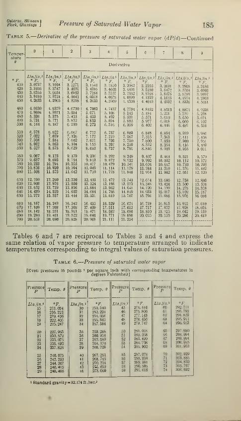
Osborne, StimsonFiock, Oinnings Pressure of Saturated Water Vapor 185
Table 5.—Derivative of the pressure of saturated water vapor (dP/d)—Continued
Temper-ature
e
1 2 3 4 5 6 7 8 9
Derivative
F.Lbs./ in. 2
° F.Lbs./in.*
° F.Lbs./in?
° F.Lbs./in?
° F.Lbs./in?
° F.Lbs./in.*
O FLbs./in*°F.
Lbs./in*° F.
Lbs.ifn.i°
F.
Lbs./in.i° F.
:\. 8186410 3. 0737 3. 1004 3. 1271 3. 1540 3. 1810 3.2082 3. 2355 3. 2631 3. 2908420 3. 3466 3. 3747 3. 4031 3.4316 3. 4603 3. 4891 3. 5180 3. 5472 3. 5764 :{. 6060430 3. 6355 3. 6654 3. 6953 3. 7254 3. 7557 3. 7862 3.8168 3. 8475 3. 8786 :<,.'MYJ7440 3. 9410 3. 9724 4.0041 4. 0358 4. 0678 4. 0999 4. 1322 4. 1648 4. 1974 4. 2303450 4.2633 4.2965 4. 3298 4. 3633 4. 3969 4. 4308 4. 4649 4. 4992 4. 5336 4. 5681
460 4. 6030 4. 6379 4. 6730 4. 7083 4. 7437 4. 7794 4. 8152 4.8513 4. 8874 4. 9238470 4. 9604 4. 9971 5.034 5.071 5.108 5.140 5.184 5.221 5. 259 5.298480 5.336 5.375 5.413 5.453 5.492 5.531 5.571 5. 010 5. 650 5.691490 5.731 5.771 5.812 5.853 5.894 5.935 5.977 6.018 6.060 6. 102500 6.144 6.187 6.230 6.273 6.316 6.359 6.402 6.446 6.489 6.534
510 6.578 6.622 6.667 6.712 6.757 6.803 6.848 6.894 6.939 6.986520 7.032 7.079 7.126 7. 172 7.219 7.267 7.315 7. 363 7.411 7.458530 7.506 7.554 7.602 7.651 7.700 7.750 7.800 7.850 7.900 7.951540 8.002 8.053 8.104 8.155 8. 207 8.259 8.312 8.364 8.416 8.469550 8.522 8.575 8.629 8.683 8.737 8.791 8.846 8.901 8.956 9.011
560 9.067 9.123 9.179 9.236 9.292 9.349 9.407 9.464 9.521 9.579570 9.637 9.695 9.754 9.813 9.872 9.932 9.992 10. 052 10. 112 10. 172580 10. 233 10. 294 10. 355 10.417 10. 479 10. 541 10. 604 10. 667 10. 730 10. 793590 10. 856 10. 920 10. 984 11. 049 11. 114 11.179 11. 244 11.310 11. 376 11.442600 11. 508 11. 575 11.642 11.710 11. 778 11.846 11.914 11. 982 12. 051 12. 120
610 12. 190 12. 260 12. 330 12. 401 12. 472 12.543 12.614 12. 686 12. 758 12. 830620 12. 903 12. 976 13. 050 13. 124 13. 198 13. 273 13. 348 13. 424 13. 500 13. 576630 13. 652 13.729 13. 806 13. 884 13. 962 14. 041 14. 120 14. 199 14. 278 14. 358640 14. 439 14. 520 14. 602 14. 684 14. 766 14. 849 14. 933 15.017 15. 102 15. 187650 15. 272 15. 357 15. 444 15. 531 15. 619 15. 707 15. 796 15. 886 15. 976 16. 066
660 16. 157 16. 249 16. 342 16. 435 16. 529 16. 624 16. 719 16.815 16.912 17. 010670 17. 109 17. 208 17. 308 17. 409 17. 511 17.613 17.717 17. 822 17.928 18. 034680 18. 142 18. 251 18. 361 18. 471 18. 582 18. 696 18. 810 18. 925 19. 042 19. 159690 19. 280 19. 401 19. 522 19. 646 19. 771 19. 898 20. 025 20. 155 20.286 20. 419700 20.553 20. 690 20. 828 20. 968 21.111 21. 254
Tables 6 and 7 are reciprocal to Tables 3 and 4 and express thesame relation of vapor pressure to temperature arranged to indicate
temperatures corresponding to integral values of saturation pressures.
Table 6.
—
Pressure of saturated water vapor
[Even pressures in pounds l per square inch with corresponding temperatures in
degrees Fahrenheit]
PressureP Temp. Pressure
P Temp.Pressure
P Temp. PressureP Temp. 8
Lbs. /in. 2 °F Lbs./in. 2 °F. Lbs./in* °F. Lbs./ln.i °F.
15 213. 034 30 250. 340 45 274. 444 60 292.711
16 216.321 31 252. 224 46 275.806 61 293. 792
17 219. 436 32 254. 056 47 277. 143 62 294.859
18 222. 405 33 255. 841 48 278. 456 63 295.911
19 225. 247 34 257. 584 49 279. 747 64 296. 953
20 227. 963 35 259. 288 50 281.018 65 297. 980
21 230. 572 36 260. 954 51 282.268 66 208.994
22 233. 076 37 262. 580 52 283.499 67 299.994
23 235. 493 38 264. 170 63 284. 708 68 300. 986
24 237. 826 39 265. 728 54 285.902 69 301. 963
25 240. 075 40 267. 251 55 287.078 70 302. 929
26 242. 253 41 268. 746 50 288.238 71 808.886
27 244. 367 42 270. 214 57 289.381 72 304. 830
28 246. 415 43 2X1.650 58 290.505 73 305. 767
29 248. 405 44 273.060 59 291.616 74 300. 692
1 Standard gravity- 32. 174 ft./sec. i
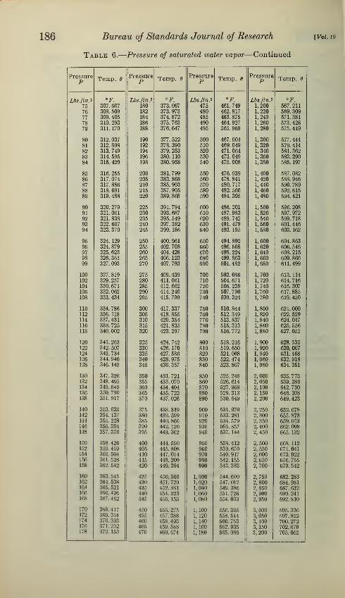
186 Bureau of Standards Journal of Research
Table 6.
—
Pressure of saturated water vapor—Continued
[Vol. 10
PressureP Temp, Pressure
P Temp, dPressureP Temp. Pressure
P Temp.
Lbs./in. 2 °F. Lbs. /in. 2 °F. Lbs./in.i °F. Lbs./in .2 °F.
75 307. 607 180 373. 067 475 461. 749 1,200 567. 211
76 308. 509 182 373. 973 480 462. 817 1,220 569. 309
77 309. 405 184 374. 872 485 463. 875 1,240 571. 381
78 310. 293 186 375. 763 490 464. 927 1,260 573.42879 311. 170 188 376. 647 495 565. 969 1,280 575. 449
80 312. 037 190 377. 522 500 467. 004 1,300 577. 44481 312. 898 192 378. 390 510 469. 049 1,320 579. 41482 313. 749 194 379. 253 520 471. 064 1,340 581. 36283 314. 595 196 380. 110 530 473. 049 1,360 583. 29084 315. 429 198 380. 958 540 475. 008 1,380 585. 197
85 316. 255 200 381. 799 550 476. 939 1,400 587. 08286 317. 074 205 383. 868 560 478. 841 1,420 588. 94687 317. 886 210 385. 903 570 480. 717 1,440 590. 789
88 318. 691 215 387. 905 580 482. 566 1,460 592. 61589 319. 488 220 389. 868 590 484. 395 1,480 594. 421
90 320. 279 225 391. 794 600 486. 201 1,500 596. 20891 321. 061 230 393. 687 610 487. 983 1,520 597. 97292 321. 838 235 395. 549 620 489. 742 1,540 599. 718
93 322. 607 240 397. 382 630 491. 479 1,560 601. 44694 323. 370 245 399. 186 640 493. 195 1,580 603. 162
95 324. 129 250 400. 961 650 494. 892 1,600 604. 86396 324. 879 255 402. 708 660 496. 568 1,620 606. 54697 325. 623 260 404.428 670 498. 224 1,640 608. 21598 326. 361 265 406. 123 680 499. 863 1,660 609. 86699 327. 093 270 407. 793 690 501. 482 1,680 611. 499
100 327. 819 275 409. 439 700 503. 086 1,700 613. 114102 329. 257 280 411. 061 710 504. 671 1,720 614. 716104 330. 671 285 412. 662 720 506. 239 1,740 616. 307106 332. 062 290 414. 240 730 507. 790 1,760 617.885108 333. 434 295 415. 799 740 509. 324 1,780 619. 450
110 334. 786 300 417. 337 750 510. 844 1,800 621. 000112 336. 118 305 418. 855 760 512. 349 1,820 622. 529114 337. 431 310 420. 354 770 513.837 1,840 624. 047116 338. 725 315 421. 835 780 515. 313 1,860 625. 556118 340. 002 320 423. 297 790 516. 772 1,880 627. 052
120 341. 263 325 424. 742 800 518. 216 1,900 628. 535122 342. 507 330 426. 170 810 519. 650 1,920 630,007124 343. 734 335 427. 580 820 521. 068 1,940 631. 468126 344. 946 340 428. 975 830 522. 474 1,960 632. 918128 346. 143 345 430. 357 840 523. 867 1,980 634. 351
130 347. 326 350 431. 721 850 525. 248 2,000 635. 773132 348. 495 355 433. 070 860 526. 614 2,050 639. 286134 349. 649 360 434. 404 870 527. 969 2,100 642. 730136 350. 790 365 435. 722 880 529. 313 2,150 646. 108138 351. 917 370 437. 026 890 530. 649 2,200 649. 423
140 353. 033 375 438. 319 900 531. 970 2,250 652. 678142 354. 137 380 439. 599 910 533. 281 2,300 655. 873144 355. 228 385 440. 866 920 534. 579 2,350 659. 013146 356. 304 390 442. 120 930 565. 857 2,400 662. 098148 357. 370 395 443. 362 940 537. 144 2,450 665. 132
150 358. 426 400 444. 590 950 538. 412 2,500 668. 112152 359. 469 405 445. 808 960 539. 670 2,550 671. 041154 360. 504 410 447. 014 970 540. 917 2,600 673. 922156 301. 528 415 448. 209 980 542. 155 2,650 676. 755158 362. 542 420 449. 394 990 543. 383 2,700 679. 642
160 363. 545 425 450. 566 1,000 544. 600 2,750 682.283162 364. 538 430 451. 729 1,020 547.012 2,800 684. 981164 365. 521 435 452. 881 1,040 549. 386 2,850 687.632166 366. 496 440 454. 023 1, 060 551. 726 2,900 690. 241168 367. 462 445 455. 153 1,080 654. 033 2,950 692. 810
170 368.417 450 456. 275 1,100 556. 305 3,000 695. 336172 369. 364 455 457. 388 1,120 558. 544 3,050 697. 822174 370. 303 460 458. 493 1,140 560. 753 3,100 700. 272178 371.232 465 459. 588 1, 160 562. 935 3,150 702. 679178 372. 153 470 460. 674 1,180 565. 086 3,200 705. 052

Osborne, StimsonlFiock, Oinnings J
Pressure of Saturated Water Vapor 187
Table 7.
—
Pressure of saturated water vapor
[Even pressures in kilograms ' per square centimeter with corresponding temperatures indegrees centigrade]
PressureP
Tempera-turee
PressureP
Tempera-ture
e
PressureP
Tempera-ture
e
PressureP
Tempera-ture
e
Kgfcm ' °C. Kg/cm » °C. Kg/cm J °C. Kg/cm > °c.
1.0 99. 072 8.0 169. 605 55 268. 693 120 323. 148
1.1 101. 764 8.2 170. 626 56 269. 842 122 324. 408
1.2 104.246 8.4 171.629 57 270. 974 124 325. 654
1.3 106. 565 8.6 172. 613 58 272. 092 126 326.884
1.4 108. 739 8.8 173. 579 59 273. 195 128 328. 098
1.5 110. 7S9 9.0 174. 526 60 274. 285 130 329. 298
1.6 112. 730 9.2 175. 458 61 275. 361 132 330. 484
1.7 114. 575 9.4 176. 375 62 276. 423 134 331.657
1.8 116. 331 9.6 177. 276 63 277. 472 136 332. 816
1.9 118.010 9.8 178. 163 64 278. 509 138 333. 958
2.0 119.617 10 179.035 65 279. 534 140 335. 088
2.1 121. 161 11 183.201 66 280.547 142 336. 206
2.2 122. 646 12 187. 079 67 281. 548 144 337.312
2.3 124.076 13 190. 708 68 282. 537 146 338.406
2.4 125. 457 14 194. 130 69 283. 517 148 339.488
2.5 126. 790 15 197. 360 70 284.485 150 340. 559
2.6 128.083 16 200. 429 71 285. 441 152 341. 616
2.7 129. 335 17 203. 351 72 286.388 154 342. 661
2.8 130. 549 18 206. 145 73 287. 326 156 343. 696
2.9 131. 730 19 208. 819 74 288. 252 158 344. 722
3.0 132. 878 20 211.385 75 289. 170 160 345. 737
3.1 133. 994 21 213. 855 76 290. 079 162 346. 742
3.2 135. 082 22 216. 234 77 290. 978 164 347. 738
3.3 136. 143 23 218. 530 78 291. 867 166 348. 723
3.4 137. 178 24 220.753 79 292. 748 168 349. 699
3.5 138. 188 25 222. 905 80 293. 621 170 350. 664
3.6 139. 178 26 224. 988 81 294. 486 172 351. 620
3.7 140. 144 27 227. 012 82 295. 343 174 352. 565
3.8 141. 089 28 228. 979 83 296. 191 176 353. 502
3.9 142. 015 29 230. 894 84 297. 032 178 354. 432
4.0 142. 922 30 232. 757 85 297. 865 180 355. 353
4.1 143. 810 31 234. 572 86 298. 690 182 356. 263
4.2 144.680 32 236. 345 87 299. 508 184 357. 165
4.3 145. 534 33 238. 075 88 300. 319 186 358. 058
4.4 146. 374 34 239. 766 89 301. 123 188 358. 943
4.5 147. 200 35 241.419 • 90 301. 919 190 359. 821
4.6 148. 008 36 243. 035 91 302. 710 192 360.689
4.7 148. 802 37 244. 617 92 303. 493 194 361.551
4.8 149. 584 38 246. 167 93 304. 270 196 362. 404
4.9 150.354 39 247. 687 94 305. 041 198 363. 248
5.0 151. 110 40 249. 176 95 305. 804 200 364.084
5.2 152. 586 41 250. 637 96 306. 562 202 364. 913
5.4 154. 018 42 252. 073 97 307. 314 204 365. 734
5.65.8
155. 409156. 760
4344
253. 483254. 866
9899
308. 060308. 799
206208
366. 550367. 358
6.06.26.46.66.8
158. 075159. 354160. 602161.820163. 008
4546474849
256. 224257.562258. 876260. 171
261.443
100102104106108
309. 533310. 986312.418313.828315. 214
210212214216218
368. 157368.949309. 734
370.511371.280
7.07.27.47.6
164.168165.303166. 412167. 497
5051
5253
262. 697263. 931
265. 149
266. 347
110112114
116
316. 580317. 930319.264320. 577
220222224225
372. 042372.800:m. 668373. 926
7.8 168. 563 54 267. 527 118 321. 8711
> Standard gravity=980.665 cm/sec.'

188 Bureau oj Standards Journal of Research [Vol. 10
VI. ESTIMATION OF ACCURACY
Numerical values of physical quantities derived from measure-ments are never in exact accord with the true values. No matterhow skillful and diligent the experimenter, there is a limit to the pre-
cision attained in each separate element of measurement and in thefinal result. The practical use of physical data is similarly subject
to limitations of accuracy. The compiler of tables of properties of
steam for practical use is obliged to choose from available experi-
mental sources the definitive values which are to be used as a basis
for formulation. This selection may be aided by the experimenterif in addition to the record of methods, standards, and units used in
his measurements, he includes also a judicious appraisal of theaccuracy of the results.
By careful study of all the factors which enter into the measure-ments, an estimate may be made of the magnitude of the systematicerror which may still remain in each factor after all known corrections
for standards and calibrations have been applied. Having madethese preliminary estimates, they may be used in a final estimateof the amount by which the results of the measurements might differ
from the truth. Such an analysis has been made for the results of
the present investigation by considering every apparent source of
error, both systematic and accidental.
The sources of systematic error which have been found significant,
include the calibration of the piston gage, the determination of thepressure corrections for the connecting line between the water sampleand the gage, the difference of the scale of the thermometer used fromthe ideal international standard temperature scale, and the determi-nation of the actual temperature of the free surface of the watersample relative to the thermometer. Each of these factors has beendiscussed earlier in its proper place. The magnitude of the accidentalerrors of measurement was deduced from the actual differences in theindividual results.
Obviously, the final appraisal of accuracy can be only approximate.If the facts were known on which an exact estimate of the system-atic errors could be based, corrections could be applied for themand their effect eliminated. The element of judgment must enterin the figure which is deduced to indicate the uncertainty remainingafter all known corrections have been applied. As such an approxi-mate appraisal, it is believed that the values formulated for thepressure of saturated water vapor do not differ from the truth bymore than 3 parts in 10,000, with the possible exception of the regionnear the critical, where the rapidly changing properties of watermake the measurements somewhat less trustworthy.
VII. ACKNOWLEDGMENTThe work presented in this report marks a further step in the
effort to establish reliability and accord in steam tables, a projectwhich has been promoted by the American Society of MechanicalEngineers through the material support of the steam power industries.It is hoped that the results here given may prove an aid in attainingthat object.
Washington, October 15, 1932.