the nona experiment - · pdf filefermilab dr. o’sheg oshinowo iwaa2012 conference...
TRANSCRIPT

Fermilab
Dr. O’Sheg Oshinowo IWAA2012 Conference
Fermilab, Batavia, IL, USA September 10-14, 2012
The NOnA
Experiment
Gary Feldman
Harvard University
Survey of the NOvA Far Detector
Babatunde O’Sheg Oshinowo Horst Friedsam
Fermi National Accelerator Laboratory Batavia, Illinois

Fermilab
Dr. O’Sheg Oshinowo IWAA2012 Conference
Fermilab, Batavia, IL, USA September 10-14, 2012 The NOvA Experiment
• North America's most advanced neutrino experiment
• NOvA is a second-generation experiment on the NuMI beamline
• The NOvA project also includes accelerator upgrades to bring the NuMI beam intensity from 400 kW to 700 kW
• Uses two detectors to look for changes in the neutrino beam as it travels:
Far Detector in Ash River, Minnesota
Near Detector at Fermilab
• Run for 6 years : 2015 – 2021
NOnA: NuMI Off-Axis ne Appearance Experiment ne = electron neutrino

Fermilab
Dr. O’Sheg Oshinowo IWAA2012 Conference
Fermilab, Batavia, IL, USA September 10-14, 2012
Ash River
Minneapolis
Duluth
International
Falls
Fermilab
Ash River
Minneapolis
Duluth
International
Falls
Fermilab
• This site is at 810 km from Fermilab, about 11 km off-axis
• The Ash River site is the farthest
available site from Fermilab in the U.S. along the NuMI beamline
Far Detector Site

Fermilab
Dr. O’Sheg Oshinowo IWAA2012 Conference
Fermilab, Batavia, IL, USA September 10-14, 2012 NOvA Detectors
NOvA Detectors:
• A 14 kTon Far Detector sited 14 mrad off the NuMI beam axis at a distance of 810 km at a distance of 11 km (Assembly underway at Ash River) • A 0.3 kTon Near Detector identical to the far detector sited 14 mrad off the NuMI beam axis at a distance of 1 km from the NuMI Target (Begin installation Spring 2013) • An 84 Ton NDOS (Near Detector On
the Surface) identical to the Near
Detector sited on the surface 107 mrad off the NuMI beam axis in the NOvA Near Detector Surface Building at Fermilab (IWAA2010; Completed and running since November 2010)

Fermilab
Dr. O’Sheg Oshinowo IWAA2012 Conference
Fermilab, Batavia, IL, USA September 10-14, 2012 NOvA Detector
The NOvA detectors are constructed from
planes of PVC modules
Extrusions have a cellular structure, with 16 isolated cells per extrusion
A module of 32 cells is constructed from
two 16-cell PVC extrusions glued together
L = 15.6 m for Far Detector L = 4.2 m for Near Detector
Modules are capped by a Manifold and an End Plate/Cap to contain the liquid
scintillator
Twelve (12) extrusion modules get placed side by side on a flat assembly table to form one plane of the Far Detector
PVC Extrusion
PVC Module
= Module Plane

Fermilab
Dr. O’Sheg Oshinowo IWAA2012 Conference
Fermilab, Batavia, IL, USA September 10-14, 2012 NOvA Block
• 32 planes make 1 NOvA block
• 5 blocks make 1 super block • NOvA block (B) configuration is as follows: B = v0h1v2h3v4h5v6h7v8h9v10 …. v20h21v22h23v24h25v26h27v28h29v30h31 where v are planes of vertical modules and h are planes of horizontal modules number of planes is counted from 0 (Upstream)
to 31 (Downstream)
• Block assembly starts from plane (or layer)
31 (h31) on the assembly table and ends
with plane 0 (v0)

Fermilab
Dr. O’Sheg Oshinowo IWAA2012 Conference
Fermilab, Batavia, IL, USA September 10-14, 2012
• The NOvA Far Detector consists of
928 (15.6 m square) planes
• Twelve (12) modules make up a plane,
and the planes alternate in having their
long dimension vertical and horizontal
• The Far Detector (FD) consists of 29 blocks: FD B0B1B2B3B4 B5……..B25B26B27B28B28
where the number of blocks is counted 0 (Upstream) to 28 (Downstream)
Far Detector
O’Sheg
15.6 m
15.6 m

Fermilab
Dr. O’Sheg Oshinowo IWAA2012 Conference
Fermilab, Batavia, IL, USA September 10-14, 2012 NOvA Far Detector Building
The NOvA Far Detector building contains
The Detector Hall at the south end
Block Assembly area at the north end

Fermilab
Dr. O’Sheg Oshinowo IWAA2012 Conference
Fermilab, Batavia, IL, USA September 10-14, 2012 The NOvA Detector Hall
• The Detector Hall will house all the 29 NOvA blocks.
• The first block will rest on the Book End on
the South Wall • The Pivoter Rails are used by the Pivoter to
transport each block to the far south end
Pivoter Rails
Book End

Fermilab
Dr. O’Sheg Oshinowo IWAA2012 Conference
Fermilab, Batavia, IL, USA September 10-14, 2012
• The Block Assembly area houses the NOvA Block Pivoter machine and the Pivoter Assembly Table that is used to build all the blocks
• All block are assembled on the assembly table while it is in its horizontal position
Block Assembly Area
Pivoter
Assembly Table (Vertical Position)

Fermilab
Dr. O’Sheg Oshinowo IWAA2012 Conference
Fermilab, Batavia, IL, USA September 10-14, 2012 Block Assembly
Alignment Posts
• Installation of the NOvA Far Detector
is underway • The Block assembly starts at the glue
machine where glue is applied to the extrusion modules
• The modules are then transported to the assembly table by the lifting fixture to be glued to the next modules to form planes (layers)
• Alignment Posts attached to the assembly table are used as guides for the module installation
• The block is assembled in its horizontal position starting first with the downstream end
• Each plane is scanned with the Laser Scanner once the plane is completed

Fermilab
Dr. O’Sheg Oshinowo IWAA2012 Conference
Fermilab, Batavia, IL, USA September 10-14, 2012
• Once a block has been finished,
the last module is painted black,
the block Pivoter is used to move
the block into place within the
detector building to the south wall
• It then pivots 90° to set the block
upright to the ideal location
• The block will then be filled with Liquid Scintillator
Block Assembly

Fermilab
Dr. O’Sheg Oshinowo IWAA2012 Conference
Fermilab, Batavia, IL, USA September 10-14, 2012
Purpose:
• Establish a surface geodetic control network • Establish a precision horizontal and vertical control network in the Far Detector building • Floor Flatness measurements • Book End as-built measurements • Pivoter Rail measurements • Pivoter Table Flatness measurements • Block measurements
Survey of NOvA Far Detector
Pivoter Rails
Book End
Pivoter Table

Fermilab
Dr. O’Sheg Oshinowo IWAA2012 Conference
Fermilab, Batavia, IL, USA September 10-14, 2012 Survey Methodology
All Survey for the Far Detector was done with:
• An API Tracker3 Laser Tracker and Spatial AnalyzerTM
• Leica Absolute Tracker AT401
• Trimble S6 Total Station
• Geodimeter Total Station
• Leica DNA03 Digital level
• Trimble GPS Receivers
• Leica HDS6100 Laser Scanner system and its associated software

Fermilab
Dr. O’Sheg Oshinowo IWAA2012 Conference
Fermilab, Batavia, IL, USA September 10-14, 2012
Ash River • Established a GPS surface geodetic control
network that connects points at Fermilab to
Ash River
• Tie surface control network to the National
Geodetic Survey’s Continuously Operating
Reference Stations (CORS) precision
geodetic network
• All long baselines are known to better than
1 cm horizontally and vertically
• The network based on the NAD83 (North
American Datum 1983) for horizontal datum
and the NAVD88 (North American Vertical
Datum 1983) for vertical datum
Far Detector Surface Geodetic Network

Fermilab
Dr. O’Sheg Oshinowo IWAA2012 Conference
Fermilab, Batavia, IL, USA September 10-14, 2012 Far Detector Building Control Network
• Established a primary precision control network
in the Far Detector building for positioning the Far Detector using the API Laser Tracker • A secondary control network on the four levels of the west wall of the Detector hall using the Leica AT401 • Primary network consists of 49 floor monuments and 36 wall monuments in the Far Detector Hall and the Detector assembly area. Secondary network consists of 44 wall monuments • Tied the new building control network to the surface network using the Geodimeter Total Station Floor
Monument
Upper Level Lower Level
Surface Network

Fermilab
Dr. O’Sheg Oshinowo IWAA2012 Conference
Fermilab, Batavia, IL, USA September 10-14, 2012 Floor Flatness Measurements
• Floor Flatness measurements using 720 grid points in the Detector Hall
made with the Laser Tracker • These measurement results will be
used for shimming the Pivoter Table pallets that the blocks sit on

Fermilab
Dr. O’Sheg Oshinowo IWAA2012 Conference
Fermilab, Batavia, IL, USA September 10-14, 2012 Book End As-Built Measurements
• The surface of the three sections of the Book End on the South Wall were measured with the Laser Tracker
• Deltas from the ideal plane defined by the Top Book End was reported to use for possible adjustments
Pivoter Rail Plane

Fermilab
Dr. O’Sheg Oshinowo IWAA2012 Conference
Fermilab, Batavia, IL, USA September 10-14, 2012 Pivoter Rail Measurements
• The surfaces of the two Pivoter Rails were mapped with the API Laser Tracker
• A plane fitted to the Pivoter Rails
measurements was used to define the NOvA Far Detector Building Local Coordinate System
Fermilab
Dr. O’Sheg Oshinowo IWAA2012 Conference
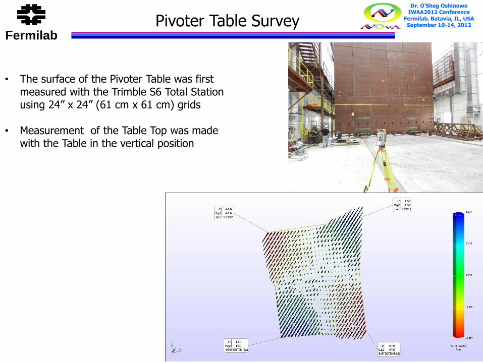
Fermilab, Batavia, IL, USA September 10-14, 2012 Pivoter Table Survey
• The surface of the Pivoter Table was first measured with the Trimble S6 Total Station using 24” x 24” (61 cm x 61 cm) grids
• Measurement of the Table Top was made with the Table in the vertical position

Fermilab
Dr. O’Sheg Oshinowo IWAA2012 Conference
Fermilab, Batavia, IL, USA September 10-14, 2012
• Flatness measurement of the east
side of the Pivoter Table was made
using the Laser Tracker with the
Table in the vertical position
• Measurements were made at spots
where the alignment posts were
installed
Pivoter Table Survey
Alignment Posts

Fermilab
Dr. O’Sheg Oshinowo IWAA2012 Conference
Fermilab, Batavia, IL, USA September 10-14, 2012
• The surface of the Pivoter Table was measured with the Laser Tracker using 24” x 24” (61 cm x 61 cm) grids
• Measurement of the Table Top was made
with the Table in the horizontal position • Based on these measurements, the Table
surface was shimmed accordingly and covered with plywood
Pivoter Table Survey

Fermilab
Dr. O’Sheg Oshinowo IWAA2012 Conference
Fermilab, Batavia, IL, USA September 10-14, 2012 NOvA Block Plane Measurements
• The surface of each of the 32 planes of the NOvA Block is scanned with the Laser Scanner located on the ceiling inverted directly above the Pivoter Assembly Table (See next presentation by Horst Friedsam) Overall Block Survey Tolerance: • Relative 2 mm (Horizontal) edge to edge; • Relative 0.75 mm or better (Vertical) between adjacent pieces • Angular tolerance of ± 2 mm/15.6 m = ± 0.13 mrad
Block on Pivoter Table
Laser Scanner

Fermilab
Dr. O’Sheg Oshinowo IWAA2012 Conference
Fermilab, Batavia, IL, USA September 10-14, 2012 What’s Next?
• The first block, Block 0, was completed on September 5, 2012 • Block 0 was tilted to its vertical position on September 10, 2012 and moved to the Detector Hall south wall Book End • Installation of Block 1 is underway • After Block 1 is completed and moved to the Detector Hall, the first two blocks will be filled with Liquid Scintillator • The blocks will be surveyed before and after filling with Liquid Scintillator using the Laser Tracker at the lower level and Trimble S6 at the higher level • 28 more blocks to go!

Fermilab
Dr. O’Sheg Oshinowo IWAA2012 Conference
Fermilab, Batavia, IL, USA September 10-14, 2012 Status NOvA Far Detector
• The first super block is scheduled to be completed by the end of the year • The Far Detector is scheduled to begin taking data in 2013 • Data taking will continue as the detector is completed in spring of 2014 • The NOvA experiment will run for six
year : 2015 – 2021

Fermilab
Dr. O’Sheg Oshinowo IWAA2012 Conference
Fermilab, Batavia, IL, USA September 10-14, 2012
I would like to thank • Alignment and Metrology Department members who participated in the NOvA Far Detector survey
• Dr. Pat Lukens, Dr. Ting Miao and David Pushka - NOvA Collaboration
Acknowledgment