the nature of hhl 73 from optical imaging and integral ... · trophotometer (pmas) in the...
TRANSCRIPT
arX
iv:0
711.
1521
v1 [
astr
o-ph
] 9
Nov
200
7
Mon. Not. R. Astron. Soc.000, 1–14 (2007) Printed 6 November 2018 (MN LATEX style file v2.2)
The nature of HHL 73 from optical imaging and Integral FieldSpectroscopy
R. Lopez,1⋆ S. F. Sanchez,2⋆ B. Garcıa-Lorenzo,3⋆ G. Gomez,3,4⋆
R. Estalella,1⋆ A. Riera5⋆ and G. Busquet1⋆ †1Departament d’Astronomia i Meteorologia, Universitat de Barcelona, Martı i Franques 1, E-08028 Barcelona, Spain.2Centro Astronomico Hispano-Aleman de Calar Alto, JesusDurban Remon 2-2, E-04004 Almerıa, Spain.3Instituto de Astrofısica de Canarias, E-38200 La Laguna, Spain4GTC Project Office, GRANTECAN S.A. (CALP), E-38712 Brena Baja, La Palma, Spain.5Dept. Fısica i Enginyeria Nuclear. EUETI de Barcelona. Universitat Politecnica de Catalunya. Compte d’Urgell 187, E-08036 Barcelona, Spain.
Accepted. Received;
ABSTRACTWe present new results on the nature of the Herbig–Haro-likeobject 73 (HHL 73, also knownas [G84b] 11) based on narrow-band CCD Hα and [SII ] images of the HHL 73 field, and Inte-gral Field Spectroscopy and radio continuum observations at 3.6 cm covering the emission ofthe HHL 73 object. The CCD images allow us to resolve the HHL 73comet-shaped morphol-ogy into two components and a collimated emission feature of∼ 4-arcsec long, reminiscentof a microjet. The IFS spectra of HHL 73 showed emission linescharacteristic of the spectraof Herbig–Haro objects. The kinematics derived for HHL 73 are complex. The profiles of the[S II ] λλ6717, 6731A lines were well fitted with a model of three Gaussian velocity com-ponents peaking atVLSR ≃ −100, −20 and +35 km s−1. We found differences among thespatial distribution of the kinematic components that are compatible with the emission froma bipolar outflow with two blueshifted (low- and high-velocity) components. Extended radiocontinuum emission at 3.6 cm was detected showing a distribution in close agreement withthe HHL 73 redshifted gas. From the results discussed here, we propose HHL 73 to be a trueHH object.IRAS21432+4719, offset 30 arcsec northeast from the HHL 73 apex,is the mostplausible candidate to be driving HHL 73, although the evidence is not conclusive.
Key words: ISM: jets and outflows – ISM: individual: [G84b] 11, HHL 73, HH379,IRAS21432+4719
1 INTRODUCTION
Herbig–Haro-like objects (HHLs) appear as bright nebulosities inthe red optical images. Spectroscopy of HHLs indicates thata frac-tion of them are reflection nebulae originated by the scattered lightfrom a stellar source associated with the nebulosity, whileonlya fraction of HHLs are Herbig–Haro (HH) objects arising fromshock-excited gas. HHL 73, also known as [G84b] 11, was firstreported by Gyulbudaghian (1984) as object 11 found in his sur-vey of DSSred plates. In these plates, the object shows a comet-shaped morphology, being located close to the western border of
⋆ E-mail: [email protected]; [email protected]; [email protected];[email protected]; [email protected];[email protected]; [email protected]† Based on observations collected at the Centro AstronomicoHispanoAleman (CAHA) at Calar Alto, operated jointly by the Max-Planck Institutfur Astronomie and the Instituto de Astrofısica de Andalucıa (CSIC) and inthe 2.6 m Nordic Optical Telescope and 2.5 m Isaac Newton Telescope atthe Observatorio del Roque de los Muchachos of the Institutode Astrofısicade Canarias.
a region with high visual extinction. In fact, HHL 73 is foundas-sociated with a dark cloud complex in Cygnus, close to the LyndsDark Cloud 1035A (LDN 1035A), and lying in a region with clearsigns of recent star formation activity. The estimated distance to theregion is900± 100 pc (Elias 1978).
The sourceIRAS21432+4719 is located close to HHL 73.Both sources are engulfed within a clump of high-density molec-ular gas, traced by the emission of the NH3 and CS molecules,whose emission peaks around the HHL 73 andIRAS21432+4719positions (see Anglada, Sepulveda & Gomez 1997 and referencestherein for a wider description on the high-density molecular gasemissions in the HHL 73 field). Emission from high-velocitymolecular gas in this field is also reported by Dobashi et al. (1993),who detect a highly asymmetric CO bipolar outflow. The emis-sion of the redshifted outflow lobe is spatially more extended thanthe blueshifted lobe and encompasses the region aroundIRASandHHL 73. In addition, the detection of a water maser near HHL 73was reported by Gyulbudaghian, Rodrıguez & Mendoza-Torres(1987).
Devine, Reipurth & Bally (1997) imaged the HHL 73 field
c© 2007 RAS

2 R. Lopez et al.
Figure 1. CCD Hα-band image of the HHL 73 field obtained at theIsaac Newton Telescope (INT, ORM). Arrows point to the HHL 73and HH 379 objects. The position ofIRAS 21432+4719 and the er-ror ellipse are marked. The tilted cross marks the position given byGyulbudaghian, Rodrıguez & Mendoza-Torres (1987) for theH2O maser.The image FOV is∼ 8.5× 6 arcmin2 . North is up and east is to the left.
through narrow-band Hα and [SII ] λλ6717, 6731A filters. Theyfind two stellar-like condensations∼ 2.5 arcmin west of HHL 73with similar Hα and [SII ] surface brightness, surrounded by dif-fuse emission. They designate their finding as the new Herbig–Haroobject HH 379. In addition, they suggest that the exciting sourceof HH 379 may be embedded within the cometary nebula whichappears in their images at a position close toIRAS21432+4719(thus, at the position given by Gyulbudaghian (1984) for HHL73).These authors also discuss a plausible association betweentheIRAS source and the undetected exciting source of HH 379. Itshould be noted that Devine, Reipurth & Bally (1997) never re-fer to the optical cometary nebula as the HHL 73 object reportedby Gyulbudaghian (1984). Later on, Davis et al. (2001, 2003)per-formed near-IR echelle spectroscopy at the HHL 73 position. Theydetect emission from H2 λ2.122µm and [FeII ] λ1.644µm lines,while no continuum emission is detected at the HHL 73 position.Both lines show a rather complex profile, the width of the [FeII ]line being roughly twice that of the H2 line. Davis et al. (2003) sug-gest that the [FeII ] emission may trace the higher-velocity compo-nent of a jet. In addition, Davis et al. (2001, 2003) also suggest thatthe optical nebula found in the Devine, Reipurth & Bally (1997)images harbours the true exciting source of HH 379, thus discard-ing the possibiility thatIRAS21432+4719 was driving HH 379.This yet undetected exciting source of HH 379 is named as HH379-IRS by these authors. In order to help with the identification ofthe sources mentioned here, we show in Fig. 1 a CCD Hα image ofthe HHL 73 field where all these sources have been marked.
With the aim of unravelling the nature of HHL 73, we includedthis target within a programme of Integral Field Spectroscopy (IFS)of Herbig–Haro objects using the Potsdam Multi-Aperture Spec-trophotometer (PMAS) in the wide-field IFU mode PPAK. Addi-tional CCD narrow-band images and radio continuum 3.6 cm datahave been analysed to complement the study. We present in this pa-per the results on the kinematics and physical conditions ofHHL 73obtained from this IFS pilot programme.
The paper is organized as follows. The observations and datareduction of CCD imaging, radio continuum and IFS observationsare described in§ 2.1, 2.2 and 2.3 respectively. Results are given in
§ 3: CCD imaging in§ 3.1, radio continuum in§ 3.2 and IFS in§3.3, including results from integrated emission (§ 3.4) and a line-profile decomposition model for [SII ] profiles (§ 3.5). A global dis-cussion is made in§ 4. In§ 5 the main conclusions are summarized.
2 OBSERVATIONS AND DATA REDUCTION
2.1 Narrow-band CCD images
Narrow-band CCD images of the HHL 73 field were made on 2006August 5 at the 2.6 m Nordic Optical Telescope (NOT) (ORM,La Palma, Spain) using the Service Time facility. The imageswere obtained with the Andalucia Faint Object SpectrographandCamera (ALFOSC). The image scale was 0.188 arcsec pixel−1.The effective imaged field was∼ 5 × 5 arcmin2. Images wereobtained through filters of Hα (central wavelength,λc = 6564 A,bandpass∆λ = 33 A, which mainly includes emission from thisline, although some contamination from [NII ] emission is alsopresent) and [SII ] (λc = 6725 A, ∆λ = 60 A), which includesthe two red [SII ] lines. The integration time was 1800 s in Hα and2400 s in [SII ]. The seeing was 0.6–0.8 arcsec. In order to checkwhether there is significant continuum contribution to the HHL 73red emission, additional exposures (600 s integration time) wereacquired through a narrow-band, off-line filter, but no continuumsignal around the HHL 73 location was detected. All the imageswere processed with the standard tasks of theIRAF1 reductionpackage. Astrometric calibration of the two final images wasperformed. In order to register the images, we used the coordinatesfrom theUSNOCatalogue2 of eight field stars well distributed onthe observed field. The rms of the transformation was 0.12 arcsecin both coordinates.
In addition to the NOT images, we also show in Fig. 1 a CCDimage of the HHL 73 field obtained on 2003 December 15 at the2.5 m Isaac Newton Telescope (INT) through a narrow-band filterof central wavelengthλc = 6564 A and bandpass∆λ = 50 A thatalso includes emission from the [NII ] λλ6548, 6583A lines. Theintegration time was 3600 s. Astrometric calibration of this imagewas also performed with an accuracy of a fraction of the pixelsize(0.24 arcsec rms in both coordinates). This image has a spatial res-olution significantly lower than that of the NOT images sincetheimage scale was 0.54 arcsec pixel−1 and, in addition, it was ob-tained under worse seeing conditions (> 3 arcsec). However, theINT image is deeper than the NOT images and has been used inour study to look for faint emission nebulae in the field that mightbe related to the HHL 73 object and/or with HH 379.
2.2 Radio continuum and H2O maser emission
We observed the 3.6 cm continuum emission towards HHL 73 withthe Very Large Array of the NRAO3 in the C configuration during
1 IRAF is distributed by the National Optical Astronomy Observatories,which are operated by the Association of Universities for Research inAstronomy, Inc., under cooperative agreement with the National ScienceFoundation.2 The USNOFSImage and Catalogue Archive is operated by the UnitedStates Naval Observatory, Flagstaff Station.3 The National Radio Astronomy Observatory is operated by AssociatedUniversities Inc., under cooperative agreement with the National ScienceFoundation.
c© 2007 RAS, MNRAS000, 1–14
Integral Field Spectroscopy of HHL 73 3
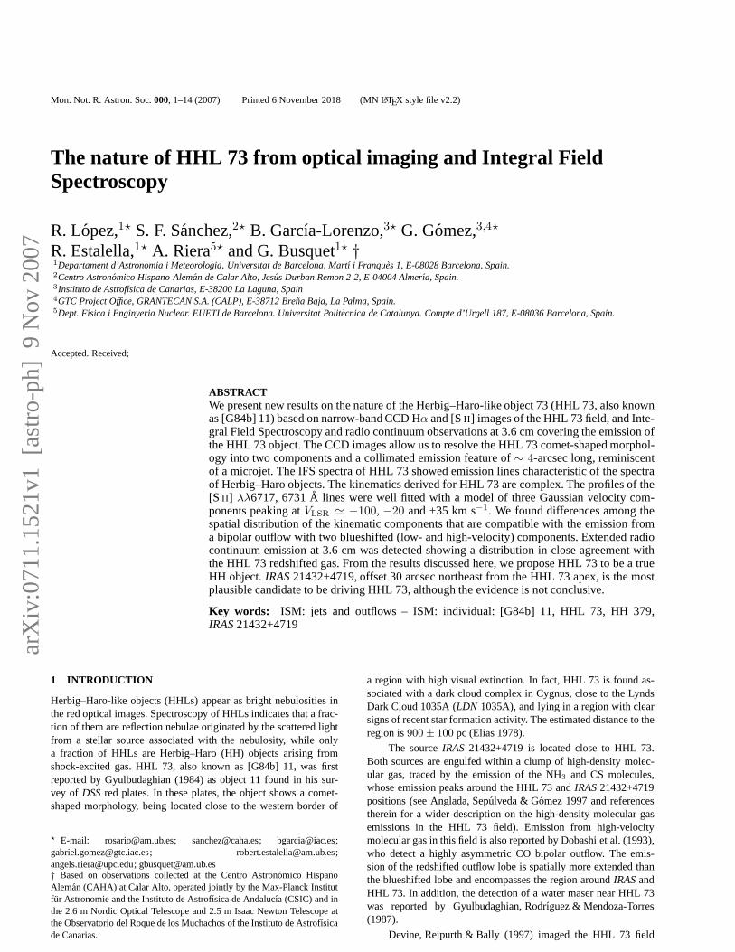
Figure 2. Close-up of the HHL 73 images obtained at the Nordic Optical Telescope (NOT, ORM) through the line filters of Hα (left) and [SII ] (right). Inboth images, the spatial structure of HHL 73 emission is resolved into two components. A microjet of∼ 4 arcsec is also visible in the two band images. TheFOV of each image is∼ 50× 42 arcsec2 . North is up and east is to the left.
1997 August 14. The phase centre was located atRA(J2000) =21h45m10.s46; Dec.(J2000) = +47◦33′21.′′2. The phase cali-brator used was 2202+422, and the bootstrapped flux density ob-tained was3.69 ± 0.07 Jy. The absolute flux density calibratorwas 00137+331 (3C48), for which a flux density of 3.15 Jy wasadopted. Clean maps were obtained using the taskMAPPRof AIPSwith the robust parameter set equal to 5, which is close to naturalweighting. Since the signal-to-noise ratio of the longest baselineswas low, we applied a(u, v)-taper function of 50 kλ. The resultingsynthesized beam size was4.7 × 4.3 arcsec2 (P.A. = −78◦), andthe achieved1σ noise level was 20µJy beam−1.
VLA archive observations of the water maser line at22.2351 GHz (616–523 transition) carried out in the B configurationduring 1994 July 4 were analysed. The phase centre was located atRA(J2000) = 21h45m08.s37; Dec.(J2000) = +47◦32′49.′′1.The bootstrapped flux obtained for the phase calibrator 2202+422was3.08 ± 0.09 Jy, and the adopted flux density for the absoluteflux calibrator (3C48) was 1.13 Jy at 1.3 cm. The observationsweremade using the 2IF mode, with a bandwidth of 6.30 MHz with 31channels of 203 kHz resolution (2.66 km s−1 at 1.3 cm) centred at−2 km s−1, plus a continuum channel that contains the central 75percent of the bandwidth. The synthesized beam was0.36 × 0.31arcsec2 (P.A. = −11◦), and the1σ noise level per spectral channelachieved with natural weight was 8 mJy beam−1.
2.3 Integral Field Spectroscopy (IFS)
Observations of the HHL 73 object were made on 2004 November22 with the 3.5 m telescope of the Calar Alto Observatory (CAHA).Data were acquired with the Integral Field Instrument PotsdamMulti-Aperture Spectrophotometer PMAS (Roth et al. 2005) us-ing the PPAK configuration that has 331 science fibres, coveringa hexagonal FOV of 74×65 arcsec2 with a spatial sampling of 2.7arcsec per fibre. In addition, PPAK comprises 36 fibres to sam-ple the sky, located∼ 90 arcsec from the centre, packed in smallbundles of six fibres each one, and distributed at the edges ofthescience hexagon. Fifteen calibration fibres are interpolated in be-tween the science and sky ones in the pseudo-slit, and connecteddirectly to the PMAS internal calibration unit (Kelz et al. 2006).The I1200 grating was used, giving an effective sampling of 0.3 Apix−1 (∼ 15 km s−1 for Hα) and covering the wavelength range
∼ 6500–7000A, thus including characteristic HH emission linesin this wavelength range (Hα, [N II ] λλ6548, 6584A and [SII ]λλ6717, 6731A). The spectral resolution (i. e. instrumental profile)is∼ 2 A FWHM (∼ 90 km s−1) and the accuracy in the determina-tion of the position of the line centroid is∼ 0.2 A (∼ 10 km s−1 forthe strong observed emission lines). We made a single pointing of1800-s exposure time centred on theSIMBADposition of HHL 73(RA(J2000) = 21h45m08.s1, Dec.(J2000) = +47◦33′6′′) cov-ering the whole optical emission of the object (∼ 30 arcsec).
Data reduction was performed using a preliminary version ofthe R3D software (Sanchez 2006), in combination withIRAF andtheEuro3Dpackages (Sanchez 2004). The reduction consists of thestandard steps for fibre-based integral field spectroscopy.A mas-ter bias frame was created by averaging all the bias frames ob-served during the night and subtracted from the science frames.The location of the spectra in the CCD was determined using acontinuum-illuminated exposure taken before the science expo-sures. Each spectrum was extracted from the science frames byco-adding the flux within an aperture of five pixels along the cross-dispersion axis for each pixel in the dispersion axis, and stored itin a row-stacked-spectrum (RSS) file (Sanchez 2004). At thedateof the observations we lacked a proper calibration unit for PPAK.Therefore, the wavelength calibration was performed iteratively.First, we illuminated the science fibres using domestrahler lampswith the telescope at the location of the objects. These lamps havewell defined emission lines in the wavelength range considered, al-though the line elements and wavelength are ignored at this step.These exposures were used to correct for distortions in the wave-length solution, fixing all the spectra to a common (ignored)so-lution. After that, the wavelength solution was found usingHgNelamps that illuminated only the calibration fibres. Differences inthe fibre-to-fibre transmission throughput were corrected by com-paring the wavelength-calibrated RSS science frames with the cor-responding continuum illuminated ones. The final wavelength so-lution was set by using the sky emission lines found in the ob-served wavelength range. The achieved accuracy for the wave-length calibration was better than∼ 0.1 A (∼ 5 km s−1). Ob-servations of a standard star were used to perform a relativefluxcalibration. A final datacube containing the 2D spatial plusthespectral information of HHL 73 was then created from the 3Ddata by usingEuro3D tasks to interpolate the data spatially until
c© 2007 RAS, MNRAS000, 1–14

4 R. Lopez et al.
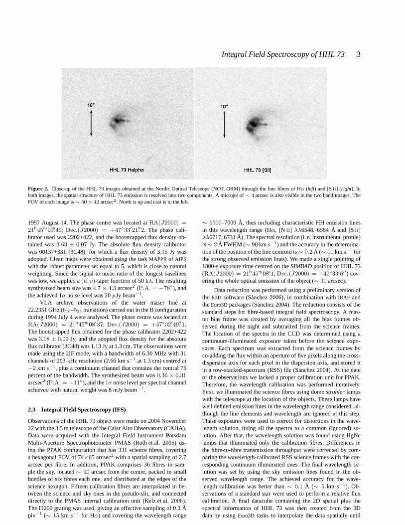
Figure 3. Left panel: Continuum emission at 3.6 cm (white contours) overlaid on theK-band2MASSimage (grey scale). The cross marks the position of theH2O maser detected by Gyulbudaghian, Rodrıguez & Mendoza-Torres (1987). The synthesized beam is shown at the bottom leftcorner, and the black ellipseindicates theIRASerror ellipse.Right panel: Detail of the 3.6 cm continuum emission towards HHL 73 (white contours) overlaid on the [SII ] image (greyscale). In both panels, contours levels are−5, −3, 2, 3, 5, 7, and 9 times the rms of the map, 20µJy beam−1.
reaching a final grid of 2.16 arcsec of spatial resolution and0.3A of spectral resolution. Further manipulation of this datacube, de-voted to obtaining integrated emission line maps, channel maps andposition–velocity maps, were made using several common-userstasks ofSTARLINK, IRAF andGILDAS astronomical packages andIDA (Garcıa-Lorenzo, Acosta-Pulido & Megias-Fernandez 2002),a specific suit ofIDL software for analysing 3D data.
3 RESULTS
3.1 Narrow-band CCD images
Figure 1 shows the Hα image of the HHL 73 field obtained at theINT. The HHL 73 object appears projected on a dark cloud nearits southwestern border. The object presents in this Hα image thecomet-shaped morphology already found in theDSSplates. Be-cause of the low effective spatial resolution of the image result-ing from both the pixel scale and the seeing, we were unable toresolve any structure in the morphology of the Hα emission. Nei-ther were we able to elucidate from this image whether the emis-sion of HHL 73 originates mainly from scattered starlight from anembedded point-source, as suggested by Devine, Reipurth & Bally(1997), or whether the emission mainly arises from gas photoion-ized or shock-excited by an external source. The error ellipse ofIRAS21432+4719 does not encompass HHL 73. From the astrome-try performed on the Hα image, we derived that theIRAScatalogueposition is∼ 30 arcsec northeast of the HHL 73 Hα emission peak(∼ 0.13 pc for a distance of 900 pc). A2MASSsource is foundvery close to HHL 73 (there is an offset of∼ 1.5 arcsec betweenthe position given for the infrared source in the2MASScatalogueand the position of the Hα emission peak of HHL 73). The neb-ulosities cited by Devine, Reipurth & Bally (1997) as HH 379 arealso visible in our INT image close to a bright field star (see Fig.1). However, despite a careful inspection of the HHL 73 field im-aged in Hα, we were unable to identify any other nebular emissionsuggestive of being part of a putative optical jet related toHH 379.
The narrow-band Hα and [SII ] images obtained at the NOThave less depth than the INT image. However the higher spatial res-olution achieved in the NOT images make them suitable for resolv-ing the structure of the HHL 73 object. Fig. 2 shows the close-upof the NOT images including the HHL 73 object in the Hα (right)
and [SII ] (left) bands. As can be seen from the figure, these imagesallow us to resolve several components in the emission of HHL73:the comet-shaped morphology detected in the optical INT imagesof lower spatial resolution now appears split into two componentsof different surface brightness with a darker lane between them.The estimated distance between the peaks of the two HHL 73 com-ponents is∼ 2.5 arcsec (∼ 0.01 pc for a distance of 900 pc). In ad-dition, a lower brightness and more collimated emission tail, show-ing a couple of brightness enhancements suggestive of the “knots”of a microjet, emanates from the brighter northwestern componentand extends∼ 4 arcsec towards the west at P.A.= 267◦. Allthese HHL 73 components are found in both NOT images. How-ever, some differences are appreciated when the emission from thetwo bands is compared: the northwestern component is the brighterone in both filters, Hα and [SII ]. The southeastern component ap-pears dimmer, as compared with the northwestern one, in Hα thanin [S II ]. The emission tail is brighter and has higher collimation in[S II ] than in Hα (as would be expected from a jet). Furthermore,while the emission peak positions of Hα and [SII ] are coincidentin the southeastern component, the Hα peak position in the north-western component is offset by∼ 0.8 arcsec towards the southwestfrom the [SII ] emission peak position. Thus, differences in the ex-citation conditions between the two HHL 73 components mightbepresent.
Finally, note that the position angle of HH 379, as seen fromHHL 73, is 262◦ (Davis et al. 2001, 2003), close to that of theHHL 73 microjet. Thus, although the deep INT Hα image doesnot show any other nebulosity connecting both emissions, HH379could form part of the HHL 73 optical outflow, provided thatthe outflow direction undergoes a bending of∼ 5◦, as seen inother optical outflows propagating in a inhomogeneous medium(Lopez et al. 1995).
3.2 Centimetre continuum and H2O maser emission
In order to complement the CCD and IFS data of HHL 73, we anal-ysed the data of the emission at radio wavelengths availablefor theHHL 73 field.
c© 2007 RAS, MNRAS000, 1–14
Integral Field Spectroscopy of HHL 73 5
Table 1.Parameters of the continuum sources detected in the HHL 73 region.
Position Flux densitya Deconv. size P.A.Source α(J2000) δ(J2000) (mJy) (arcsec) (deg)
VLA 1 (HHL 73) 21h45m08.s15 47◦33′05.′′6 0.26±0.02 3.6×2.0 170VLA 2 21h45m12.s77 47◦33′43.′′6 0.33±0.03 7.5×0.0 9
a Corrected for primary beam response.
3.2.1 Centimetre continuum emission
Figure 3 (left panel) shows the continuum map at 3.6 cm towardsHHL 73 overlaid on theK-band2MASSimage. We detected twocentimetre sources, VLA 1 and VLA 2, separated∼ 47 arcsec(0.2 pc in projection at the distance of the source), locatednear thecatalogue position ofIRAS21432+4719. Both centimetre sourcesare also associated with2MASSpoint sources. In Table 1 we listthe positions, flux densities and deconvolved sizes of the detectedsources in the HHL 73 region. In Fig. 3 (right panel) we show the3.6 cm centimetre continuum emission arising from the HHL 73object overlaid on the [SII ] image. The peak position of the cen-timetre source VLA 1 is close (∼ 0.7 arcsec south) to the posi-tion of the [SII ] emission peak. The centimetre emission from theHHL 73 object is slightly elongated towards the secondary peakdetected in the [SII ]-band images to the southeast.
3.2.2 H2O maser emission
In 1985 H2O maser emission was detected towards HHL 73 byGyulbudaghian, Rodrıguez & Mendoza-Torres (1987) using the 37m radio telescope of the Haystack Observatory. The H2O maserwas located 10.2 arcsec west of the HHL 73 object, with a posi-tional uncertainty that can be estimated at∼15 arcsec, making itdifficult to ascertain whether or not the maser is associatedwithHHL 73. In the archive observations analysed here we did not de-tect H2O maser emission towards HHL 73 above a6σ limit, in-dicating that at the epoch of observation (1994 July) the maserwas out. The upper limit estimated for the peak intensity of theH2O maser emission was 48 mJy beam−1, corresponding to a mainbeam brightness temperature upper limitTMB = 1000 K.
3.3 IFS: Integrated line-emission maps
3.3.1 Emission line images
We detected emission from characteristic HH lines within the ob-served wavelength range (Hα, [N II ] λλ6548, 6584A and [SII ]λ6717, 6731A). Narrow-band images for these lines were gener-ated from the datacube. For each position, the flux of the emissionline was obtained by integrating the signal over the whole wave-length range covered by the line and subtracting a continuumob-tained from the wavelengths adjacent to the emission line.
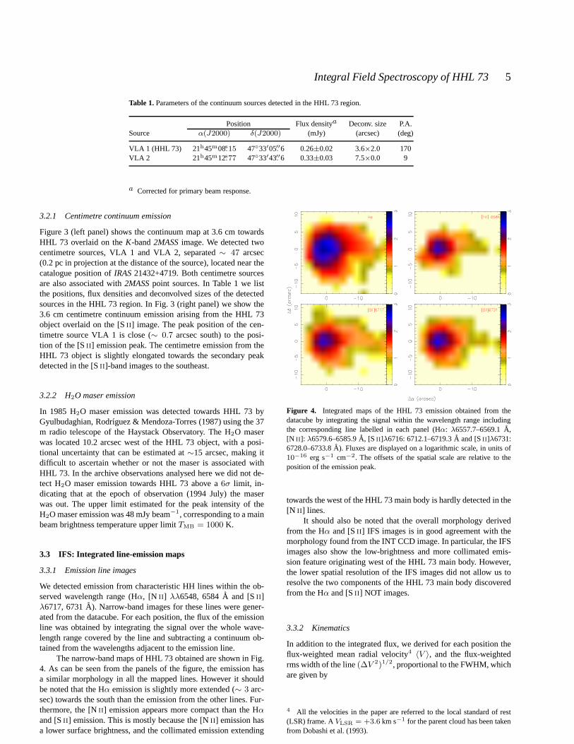
The narrow-band maps of HHL 73 obtained are shown in Fig.4. As can be seen from the panels of the figure, the emission hasa similar morphology in all the mapped lines. However it shouldbe noted that the Hα emission is slightly more extended (∼ 3 arc-sec) towards the south than the emission from the other lines. Fur-thermore, the [NII ] emission appears more compact than the Hα
and [SII ] emission. This is mostly because the [NII ] emission hasa lower surface brightness, and the collimated emission extending
Figure 4. Integrated maps of the HHL 73 emission obtained from thedatacube by integrating the signal within the wavelength range includingthe corresponding line labelled in each panel (Hα: λ6557.7–6569.1A,[N II ]: λ6579.6–6585.9A, [S II ]λ6716: 6712.1–6719.3A and [SII ]λ6731:6728.0–6733.8A). Fluxes are displayed on a logarithmic scale, in units of10−16 erg s−1 cm−2. The offsets of the spatial scale are relative to theposition of the emission peak.
towards the west of the HHL 73 main body is hardly detected in the[N II ] lines.
It should also be noted that the overall morphology derivedfrom the Hα and [SII ] IFS images is in good agreement with themorphology found from the INT CCD image. In particular, the IFSimages also show the low-brightness and more collimated emis-sion feature originating west of the HHL 73 main body. However,the lower spatial resolution of the IFS images did not allow us toresolve the two components of the HHL 73 main body discoveredfrom the Hα and [SII ] NOT images.
3.3.2 Kinematics
In addition to the integrated flux, we derived for each position theflux-weighted mean radial velocity4 〈V 〉, and the flux-weightedrms width of the line(∆V 2)1/2, proportional to the FWHM, whichare given by
4 All the velocities in the paper are referred to the local standard of rest(LSR) frame. AVLSR = +3.6 km s−1 for the parent cloud has been takenfrom Dobashi et al. (1993).
c© 2007 RAS, MNRAS000, 1–14
6 R. Lopez et al.
Figure 5. Flux-weighted mean velocity maps. Velocities (km s−1) are re-ferred to theVLSR of the parent cloud. The offsets of the spatial scaleare relative to the position of the emission peak. Contours of the inte-grated flux of the corresponding line have been overlaid. Thelowest contourlevel is7 × 10−17 erg s−1 cm−2 and the contour spacing is3 × 10−17
erg s−1 cm−2.
〈V 〉 =1
I
∫
line
IV V dV (1)
and
∆V2 =
1
I
∫
line
IV (V − 〈V 〉)2 dV, (2)
where
I =
∫
line
IV dV (3)
In spite of the spatial extension of the emission being quitecom-pact, the velocity field derived for〈V 〉 appears rather complex forall the lines and shows appreciable changes through HHL 73, ascan be seen from Figure 5.
For all the mapped lines, the gas appears blueshifted aroundthe emission peak, with〈V 〉 values of−20 km s−1 for Hα and[N II ], and−2.0 km s−1 for the [SII ] lines. However, the highestblueshifted velocities are found∼ 5 arcsec west of the emissionpeak position, where values of−50 km s−1 for Hα and [NII ], and−32.0 km s−1 for the [SII ] lines have been derived.
The FWHM values obtained from the(∆V 2)1/2, correctedfrom the instrumental profile, are high for all the mapped lines.Around the emission peak position, FWHMs are∼ 190 km s−1
for the Hα line and∼ 100 km s−1 for the [N II ] and [SII ] lines.These values are representative of the FWHMs found in the wholeemitting region, although the FWHMs slightly increase towards thesoutheast and decrease towards the west from the emission peak po-sition. Such large line widths might be indicating turbulent gas mo-tions, which are more important close to the position proposed byDavis et al. (2001, 2003) for an unseen embedded exciting source.Another possibility is that the high FWHM values derived weredue to the contribution of several kinematic components of the lineprofiles. We shall analyse this possibility later by using a multicom-ponent line profile model to fit the [SII ] profiles.
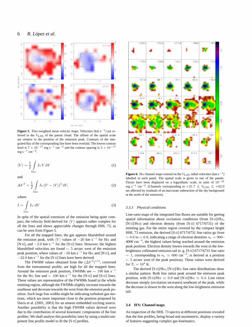
Figure 6. Hα channel maps centred on theVLSR radial velocities (km s−1)labelled in each panel. The spatial scale is given in one of the panels.Fluxes have been displayed on a logarithmic scale, in units of 10−16
erg s−1 cm−2. (Channels corresponding to+21.7 6 VLSR 6 +62.9are affected by residuals of an inaccurate subtraction of the sky backgroundat the north of the emission).
3.3.3 Physical conditions
Line-ratio maps of the integrated line fluxes are suitable for gettingspatial information about excitation conditions (from [SII ]/Hα,[N II ]/Hα) and electron density (from [SII ] 6717/6731) of theemitting gas. For the entire region covered by the compact brightHHL 73 emission, the derived [SII ] 6717/6731 line ratios go from∼ 0.6 to∼ 0.9, indicating a range of electron densitiesne = 900–4000 cm−3, the highest values being reached around the emissionpeak position. Electron density lowers towards the west in the low-brightness collimated emission tail (e. g. [SII ] 6717/6731 line ratio∼ 1, corresponding tone ≃ 600 cm−3, is derived at a position∼ 5 arcsec west of the peak position). These values were derivedfor Te = 104 K.
The derived [SII ]/Hα, [N II ]/Hα line ratio distributions showa similar pattern. Both line ratios peak around the emissionpeakposition, with [SII ]/Hα ≃ 0.9 and [NII ]/Hα ≃ 0.4. Line ratiosdecrease steeply (excitation increases) southeast of the peak, whilethe decrease is slower to the west along the low-brightness emissiontail.
3.4 IFS: Channel maps
An inspection of the HHL 73 spectra at different positions revealedthat the line profiles, being broad and asymmetric, display avarietyof features suggesting complex gas kinematics.
c© 2007 RAS, MNRAS000, 1–14

Integral Field Spectroscopy of HHL 73 7
Figure 7. Same as Fig. 6, but for [NII ] λ6584A.
Figure 8. Same as Fig. 6, but for the [SII ] 6717A emission line.
We will now analyse the behaviour of the emission as a func-tion of velocity. First, we obtained the Hα, [N II ] and [SII ] channelmaps to explore the 3D structure of the physical conditions as afunction of the radial velocity. Furthermore, to analyse the com-plex line profiles found along the HHL 73 emission, we extractedspectra for each spaxel within the area covered by the emission andwe fitted the line profiles through a multicomponent line profilemodel.
3.4.1 Spatial distribution of the emission
A more detailed sampling of the gas kinematics was obtained byslicing the datacube into a set of velocity channels along each emis-sion line profile, thus providing a “tomograph” of the emissionline, not restricted to the centroid of the line, but including also thewings. Each slice was made for a constant wavelength bin of 0.3 A,
Figure 9. Position–Velocity diagram of the Hα emission for a cut alongthe Dec. axis atRA ≃ 6.5 arcsec west of the position of the intensity peak.The∆δ = 0 position is marked by the dashed line. The contour spacing is10 per cent of the peak intensity.
Figure 10. Position–Velocity diagram of the Hα emission for a cut alongthe RA axis atDec. ≃ 2.2 arcsec south of the position of the intensity peak.The∆α = 0 position is marked by the dashed line. The contour spacing is10 per cent of the peak intensity.
corresponding to a velocity bin of∼ 14 km s−1. The channel mapsobtained for Hα, [N II ] λ6584A and [SII ] λ6717A are shown inFigs 6, 7 and 8 respectively. As we used the same wavelength binfor all the lines, the central velocity of a given channel mapdiffersslightly from a line to another.
As can be seen from Figs 6 and 8, the spatial distribution ofthe Hα and [SII ] emission found from the line-integrated IFS maps(i. e. the compact, bright region that extends towards the west in alow-brightness and collimated tail) is also found in all theveloc-ity channel maps ranging from blueshiftedVLSR velocities of−30km s−1 up to redshifted velocities of+20 km s−1 in both emissionlines.
The emission spreads over a wide velocity range for all themapped lines, the span of the velocity range being slightly differ-ent for each line. The Hα emission extends over the widest rangeas compared with the other lines, covering a range∼ 400 km s−1
wide, from−185 to +200 km s−1. The strongest and more ex-tended Hα emission is found for the velocity channels ranging from−50 to+20 km s−1. The [SII ] emission is detected within a veloc-ity range∼ 250 km s−1 wide, from−145 to +100 km s−1. Thestrongest and more extended [SII ] emission is found for the veloc-
c© 2007 RAS, MNRAS000, 1–14

8 R. Lopez et al.
ity channels ranging from−50 to+45 km s−1. The [NII ] emissionis detected within a velocity range∼ 300 km s−1 wide, from−170to+105 km s−1. The [NII ] emission presents a similar spatial ex-tension in most of the velocity channels since the low-brightnessemission tail is hardly detected in the [NII ] line.
Furthermore, we performed position–velocity (PV ) diagramsat different right ascension and declination positions, both in theHα and [SII ] lines. Two of these Hα cuts at selected positions areshown in order to illustrate more clearly a trend found in theveloc-ity distribution of the emission.
Figure 9 shows thePV diagram obtained for a cut at RA≃6.5 arcsec west of the position of the emission peak (marked in thefigure by a dashed line). This cut along the declination axis has beendone at an RA position that intersects the beginning of the colli-mated emission tail. The figure clearly shows that the overall emis-sion appears blueshifted north and south of the emission peak, atVLSR ≃ −110 km s−1. Another velocity component is also foundpeaking at∼ −70 km s−1. Furthermore, note that the spatial dis-tribution of the velocities is slightly asymmetric, with the range ofvelocities increasing from north to south: e. g. the velocities rangefrom −130 to −15 km s−1 at ∼ 2 arcsec north of the emissionpeak, while the velocities range from−110 to−45 km s−1 at∼ 2arcsec south of the emission peak.
Figure 10 shows thePV diagram obtained for a cut at Dec.≃2.2 arcsec south of the position of the emission peak. For thiscut along the RA axis, the figure shows that there is also a clearasymmetry in the spatial distribution of velocities: the emission atblueshifted velocities is spatially more extended towardsthe west,while at redshifted velocities it is is more extended towards the eastof the peak emission position. Two blueshifted velocity compo-nents, peaking at∼ −70 and∼ −25 km s−1, are also detectedfor this cut.
The inspection of differentPV diagrams obtained at severalpositions up to6 10 arcsec around the emission peak revealeda general trend, both in the Hα and [SII ] lines, in the highestblueshifted velocities appearing towards the west of the emissionpeak position, with the velocity values increasing from west to eastalong HHL 73. This signature of a two-velocity distributionin theemission can be hardly appreciated in the channel maps.
3.4.2 Density and excitation conditions
We also explored the behaviour of the density and excitationas afunction of the velocity by generating the line ratio channel mapsfor a velocity range from−135 to +110 km s−1.
Regarding the kinematics of the emission, the [SII ] 6717/6731line-ratio channel maps indicate thatne decreases with increasingvelocities: the blueshifted gas has higherne than the redshifted gas.This trend is found at different position along the HHL 73 emission.Around the position of the emission peak, we derivedne ≃ 2200cm−3 for the−80 km s−1 velocity channel, whilene ≃ 740 cm−3
is derived for the−55 km s−1 velocity channel.Regarding the spatial distribution of the emission, the [SII ]
6717/6731 line ratio channel maps indicate thatne decreases fromeast to west for all the velocity channels, thene variations beingdifferent depending on the velocity. In fact, the variations foundfor ne along the east–west axis seem to decrease with increasingvelocity: e. g. in the−80 km s−1 channel,ne changes from∼ 4200to∼ 740 cm−3 (i. e. a factor of∼ 5) as we move∼ 10 arcsec fromeast to west; in contrast,ne only changes from∼ 1400 to ∼ 490cm−3 for the same spatial displacement in the +82 km s−1 channel.
The [SII ]/Hα line-ratio channel maps show an increasing
Figure 11. Spectrum extracted at the emission peak position. Flux has beennormalized to the flux of the Hα peak. The characteristic HH emission lines(Hα, [N II ] λ6548, 6583A and [SII ] λ6717, 6731A) are clearly seen.
Figure 12. Two-dimensional distribution diagram of the observed spec-tra in the spectral window 6553.1–6590.7A, including the Hα and [NII ]λ6584A lines. Each spectrum has been obtained by averaging the spectrawithin an aperture of2× 2 spaxels (∼ 4× 4 arcsec2) and its intensity hasbeen normalized to the Hα peak. Spectra are overlaid on the Hα integratedmap obtained as in Fig. 4.
trend (i. e. decreasing excitation) with increasing velocity, fromblueshifted velocities up to a velocity of∼ +40 km s−1. Forhigher redshifted velocities, line-ratio values decrease(i. e. exci-tation increases). Thus the behaviour derived from the lineratios isthat the excitation is higher at high absolute velocity values (bothblueshifted and redshifted) than at low (absolute) velocity values.
Regarding the spatial distribution, the general trend found foreach velocity channel is a decrease in the line ratios (i. e. an increaseof excitation) from east to west.
3.5 IFS: Line-profile multicomponent analysis
Figure 11 shows the spectrum extracted at the Hα emission peakposition. As can be seen in the figure, the spectrum is closelyremi-niscent of the characteristic shock-excited HH spectra. Note in ad-dition that the line profiles are broad and asymmetric, suggestingthat multiple kinematic components are contributing to theline pro-file. Furthermore, the inspection of the spectra extracted at differentpositions over HHL 73 reveals that the line profiles display avariety
c© 2007 RAS, MNRAS000, 1–14
Integral Field Spectroscopy of HHL 73 9
Figure 13. Same as Fig. 13, but for the [SII ] emission. The spectral windowselected for this plot is 6706.4–6739.5A.
of features. Around the emission peak, line profiles are asymmetricand broad, with a faint blue double peak suggesting the presenceof several gaseous systems. To the north and south of the emissionpeak, the profiles clearly have contributions from at least two com-ponents, showing double peaks and/or broad wings. Towards thewest of the emission peak, in the low-brightness collimatedemis-sion tail, the line profiles are more complex, showing blue and redshoulders as well as broad wings. All the emission lines in the ob-served spectral range show similar features to those described here,as can be seen in Figs 12 and 13, where the spectra for the spectralranges which include the Hα and [NII ] λ6584A (Fig. 12) and the[S II ] λλ6717, 6731A emission lines (Fig. 13) have been overlaidon the flux maps obtained by integrating the signal within thesamespectral range.
The complex line-profile pattern appears in both the Hα andin the [SII ] lines. We used the [SII ] lines to perform a line-profiledecomposition to reproduce the profiles of the HHL 73 spectra,since the [SII ] emission should be less contaminated from the emis-sion of a putative, undetected source and thus, should better tracethe kinematics of the shock-excited outflow gas. The [SII ] lineprofiles were well reproduced by assuming the contribution fromthree kinematic components. The line-profile decomposition wasobtained from a model including three Gaussian components.TheGaussian fitting was performed using theDIPSO package of theSTARLINK astronomical software. The wavelength difference be-tween the two [SII ] lines was fixed according to their correspond-ing atomic parameters. Furthermore, the same FWHM of the Gaus-sian in each of the two [SII ] lines was assumed for each componentof the profile.
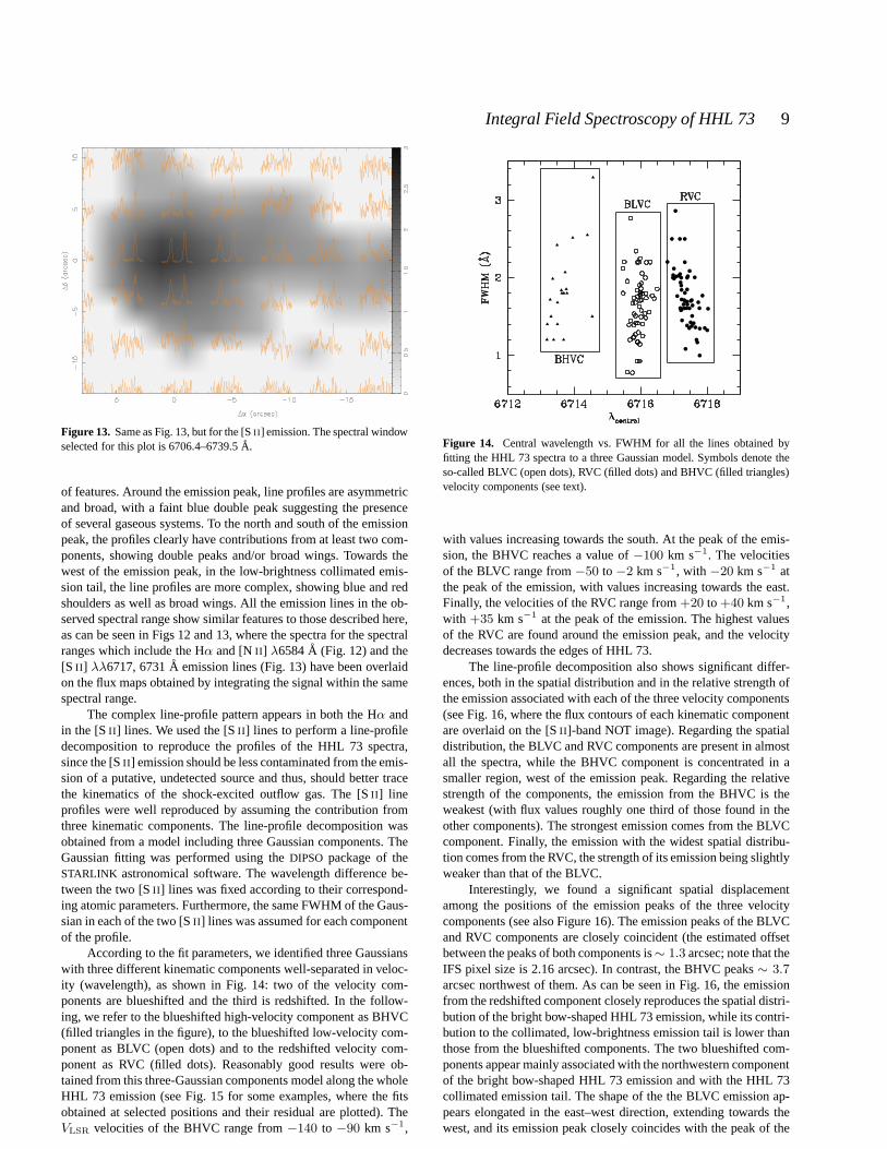
According to the fit parameters, we identified three Gaussianswith three different kinematic components well-separatedin veloc-ity (wavelength), as shown in Fig. 14: two of the velocity com-ponents are blueshifted and the third is redshifted. In the follow-ing, we refer to the blueshifted high-velocity component asBHVC(filled triangles in the figure), to the blueshifted low-velocity com-ponent as BLVC (open dots) and to the redshifted velocity com-ponent as RVC (filled dots). Reasonably good results were ob-tained from this three-Gaussian components model along thewholeHHL 73 emission (see Fig. 15 for some examples, where the fitsobtained at selected positions and their residual are plotted). TheVLSR velocities of the BHVC range from−140 to −90 km s−1,
Figure 14. Central wavelength vs. FWHM for all the lines obtained byfitting the HHL 73 spectra to a three Gaussian model. Symbols denote theso-called BLVC (open dots), RVC (filled dots) and BHVC (filledtriangles)velocity components (see text).
with values increasing towards the south. At the peak of the emis-sion, the BHVC reaches a value of−100 km s−1. The velocitiesof the BLVC range from−50 to −2 km s−1, with −20 km s−1 atthe peak of the emission, with values increasing towards theeast.Finally, the velocities of the RVC range from+20 to+40 km s−1,with +35 km s−1 at the peak of the emission. The highest valuesof the RVC are found around the emission peak, and the velocitydecreases towards the edges of HHL 73.
The line-profile decomposition also shows significant differ-ences, both in the spatial distribution and in the relative strength ofthe emission associated with each of the three velocity components(see Fig. 16, where the flux contours of each kinematic componentare overlaid on the [SII ]-band NOT image). Regarding the spatialdistribution, the BLVC and RVC components are present in almostall the spectra, while the BHVC component is concentrated inasmaller region, west of the emission peak. Regarding the relativestrength of the components, the emission from the BHVC is theweakest (with flux values roughly one third of those found in theother components). The strongest emission comes from the BLVCcomponent. Finally, the emission with the widest spatial distribu-tion comes from the RVC, the strength of its emission being slightlyweaker than that of the BLVC.
Interestingly, we found a significant spatial displacementamong the positions of the emission peaks of the three velocitycomponents (see also Figure 16). The emission peaks of the BLVCand RVC components are closely coincident (the estimated offsetbetween the peaks of both components is∼ 1.3 arcsec; note that theIFS pixel size is 2.16 arcsec). In contrast, the BHVC peaks∼ 3.7arcsec northwest of them. As can be seen in Fig. 16, the emissionfrom the redshifted component closely reproduces the spatial distri-bution of the bright bow-shaped HHL 73 emission, while its contri-bution to the collimated, low-brightness emission tail is lower thanthose from the blueshifted components. The two blueshiftedcom-ponents appear mainly associated with the northwestern componentof the bright bow-shaped HHL 73 emission and with the HHL 73collimated emission tail. The shape of the the BLVC emissionap-pears elongated in the east–west direction, extending towards thewest, and its emission peak closely coincides with the peak of the
c© 2007 RAS, MNRAS000, 1–14

10 R. Lopez et al.
Figure 15. Observed spectra (black histograms) and fits (dashed magentalines) obtained from the model of three Gaussian componentsapplied tothe [SII ] λλ6717, 6731A emission lines. The individual components areshown at the bottom of each panel. The same colour indicates the samecomponent in each line. Residuals obtained subtracting thefit from the ob-served spectra are plotted in green. Labels in the left corner of each plotindicate the offset of each observed spectrum from the [SII ] emission peak.
[S II ] emission found in the narrow-band NOT images. Finally, theemission from the BHVC, located in a smaller area, also appearsslightly elongated in the east–west direction, peaking∼ 4 arcsecwest of the [SII ] emission peak. Note however that a clear asso-ciation of each kinematic component with a given morphologicalcomponent of the HHL 73 [SII ] emission cannot be easily de-rived only by looking to the [SII ] channel maps, since the emis-sion from the wings of the stronger BLVC and RVC emissions givean appreciable contribution to the emission at positions where theBHVC (the kinematics component with the weakest emission) islocated (e. g. west of the peak of the emission), thus contaminatingthe global emission at these positions. Finally, it should be pointedout that similar kinematic structures consisting of two blueshifted(low and high) velocity components have already been detected inClass I YSO (Takami et al. 2006) and in microjets from T Tauristars (Bacciotti et al. 2000; Lavalley-Fouquet, Cabrit & Dougados2002).
4 DISCUSSION
4.1 The origin of the HHL 73 optical emission
In all the positions covered by the HHL 73 emission, the spectraextracted from the IFS datacube appear as low-ionization, line-emission spectra with no appreciable continuum emission, (seeFigs 12 and 13). In particular, the spectrum shown in Fig. 11,corre-sponding to the emission of the∼ 2 arcsec region around the peakposition, shows no significant continuum emission superposed onthe observed lines.
We compared the [NII ]/[S II ] and [N II ]/Hα line ratio values
Figure 16. Top-left: [S II ] intensity maps obtained from the fit of the three-Gaussian model to the emission line profiles and adding the individualfluxes obtained for each velocity component.Top-right: [S II ] intensity mapfor the BLVC.Bottom-left:[S II ] intensity map for the RVC.Bottom-right:[S II ] intensity map for the BHVC. The intensity of each velocity compo-nent is overlaid on the narrow-band [SII ] NOT image.
measured at several positions around the peak emission (where thesignal-to-noise ratio is high enough to do the diagnostic with con-fidence) with those obtained from the diagnostic diagrams derivedfrom the models of Kewley & Dopita (2002). These models givethe ionization parameter(i. e. ionizing photon flux through an unitarea) of the photoionized gas found in HII and star-forming re-gions as a function of the line-flux ratios for a set of metallicities.The values found for the HHL 73 [NII ]/[S II ] and [N II ]/Hα line ra-tios cannot be simultaneously fitted by the photoionizationmodels:the [N II ]/Hα ratios are compatible with a lowionization parameterfor metallicitiesz > 0.5 z⊙; in contrast, for a wide range ofion-ization parameters, the [NII ]/[S II ] ratios are only compatible withmetallicity ranges significantly lower (0.2 6 z 6 0.5 z⊙). Thus, itdoes not seem plausible to interpret the HHL 73 optical emissionas mainly originating from photoionization from a stellar source.
In contrast, the [NII ]/Hα and [SII ]/Hα line ratio values de-rived in HHL 73 are fully compatible with those found for HHobjects (i. e. from shock-excited emission) in the current diagnos-tic diagrams such as those of Canto (1981). Both HHL 73 lineratio values correspond to diagram regions where the HH ob-jects are placed, being thus outside the regions where the spectrafrom photoionized nebula, such as the planetary nebula and theH II regions, are located. It should be noted that the values mea-sured for these two line ratios (0.4–0.6 for [NII ]/Hα and 0.9–1for [S II ]/Hα) are more compatible with the values found in HHsof high/intermediate excitation spectra than with the values foundin HHs of low-excitation spectra. The degree of excitation of theHHL 73 spectra cannot be properly settled without data from theemission in a bluer wavelength range including high excitationemission lines (e. g. [OIII ]). Note, however, that the HH objects inwhich centimetre continuum emission was reported currently showa high-excitation spectrum.
Thus, the HHL 73 IFS data suggest that the emission arisesmainly from shock-excited gas, characteristic of an HH object.
The contribution from continuum emission, if any, should bevery weak, as derived from our optical data. We generated contin-
c© 2007 RAS, MNRAS000, 1–14

Integral Field Spectroscopy of HHL 73 11
uum images from the IFS datacube by integrating, at each position,the signal over the wavelength range free of lines emission.In theseimages, we have only been able to find hints of an emission en-hancement relative to the neighbouring image background aroundthe HHL 73 position, but a at very low-level (< 3σ). In addition,the narrow-band, off-line filter NOT image fail to detect continuumemission, although it has less depth than the IFS data. This putativecontinuum contribution could arise from light scattered bydust bet-ter than from a point-like stellar source, as it extends overseveralpixels.
4.2 The origin of the near-IR emission associated withHHL 73
Let us discuss the nature of the2MASSsource found near the peakposition of HHL 73.
Regarding its size, the2MASS J-, H- andK-band images showthat the2MASSsource appears slightly extended when comparedwith other sources in the fields. Typical FWHM of the field pointsources are3.3 ± 0.2 arcsec, while the FWHMs of the2MASSsource are 5.7, 5.3 and 4.8 arcsec in theJ-, H- andK-bands respec-tively, corresponding to a deconvolved size of∼ 4 arcsec (∼ 3500AU for a distance of 900 pc).
Regarding the near-IR colour, the(J − H,H − K) colour–colour diagrams are commonly used to discriminate between pre-main sequence objects and field (main sequence and giant) stars(see e. g. Ojha et al. 2004). The near-IR colour indices of the2MASSsource derived from the2MASSphotometry,(H − K) =1.26 ± 0.09, (J − H) = 1.47 ± 0.11, place the source insidethe area corresponding to YSOs of Class II, whose near-IR emis-sion originates both from a photosphere and a circumstellardisc,but its colours are also compatible, within the photometricuncer-tainties, with being a Class I source, having thermal emission froma circumstellar envelope. Thus, from the near-IR colours, it seemsplausible to infer that the2MASSsource corresponds to a very red,embedded Class II or a Class I source (i. e. a typical outflow-drivingsource). According to current evolutionary models of PMS stars(e. g. Palla & Stahler 1993; Siess, Dufour & Forestini 2000),the2MASSsource lies in the region of the(J, J−H) colour-magnitudediagram that corresponds to low-mass YSOs with masses6 1M⊙.The size derived for the2MASSsource is compatible with that ex-pected for an evacuated cavity around a YSO. However, in thissce-nario the bulk of the near-IR emission should mainly arise fromcontinuum scattered starlight, and this does not seem to be the case.Davis et al. (2001, 2003) obtained high-resolution long-slit spectraat the HHL 73 position and were unable to detect continuum emis-sion in theH andK bands including [FeII ] (at 1.64µm) and H2(at 2.12µm) emissions. Thus, the continuum near-IR emission inHHL 73, if present, is weak.
An alternative origin for the bulk of the near-IR emissionis shock emission instead of scattered starlight. In this case, the2MASS K-band luminosity would mainly arise from the H2 2.12µm line, theH-band luminosity from the [FeII ] 1.64µm line, andthe J-band luminosity from other lines, like the [FeII ] 1.25 µmline. However, this is hard to confirm, since no spectrum coveringtheJ-band range is available, and the2MASS KandH magnitudescannot be compared reliably with the magnitudes derived from theline fluxes given by Davis et al. (2001, 2003) – the line fluxes cor-respond to the integrated emission within a0.8 × 2.7 arcsec, i. e.only a small fraction of the source size. In addition, the colour in-dices derived for the2MASSsource are also compatible with thoseexpected for reddened molecular shocks, as was modelled by Smith
(1995) for a wide range of shock parameters of molecular C- andJ-shocks, who found that embebded shocks could mimic the near-IR colours derived for Class 0 sources, both sharing the same areaof the near-IR colour diagrams. Furthermore, Davis et al. (2001,2003), from the analysis of the kinematics derived from the near-IR spectra, suggest that the [FeII ] and H2 emissions are tracing anoutflow lying close to the plane of the sky, with a blueshiftedcom-ponent towards the west and a redshifted component towards theeast.
Thus, we found no conclusive evidence for the bulk of thenear-IR emission of the2MASSsource close to the HHL 73 peakto be mainly tracing the scattered light from the YSO drivingtheoutflow. Alternatively, a shock origin for the bulk of the near-IRemission seems to be compatible with the observations.
4.3 The origin of the centimetre emission associated withHHL 73
Centimetre continuum emission arising from HH objects has beendetected in both high-mass (e. g. HH 80-81: Rodrıguez & Reipurth1989; Martı, Rodrıguez & Reipurth 1993, andIRAS16547−4247:Garay et al. 2003; Rodrıguez et al. 2005) and low-mass star-forming regions (e. g. HH 1 and HH 2: Pravdo et al. 1985;Rodrıguez et al. 1990, and HH 32A: Anglada et al. 1992). In high-mass star-forming regions, the centimetre emission has a negativespectral index, which is consistent with non-thermal synchrotronemission arising from shocks resulting from the interaction of acollimated stellar wind with the surrounding medium, whileinlow-mass star-forming regions the centimetre emission shows a flatspectrum, which is consistent with optically thin free–free thermalemission from ionized gas.
The spectral index of the centimetre HHL 73 emission can-not be derived from the present single-frequency observations. Fur-ther observations at another frequency are needed to estimate thespectral index in order to discriminate between a thermal and non-thermal origin for the centimetre emission of HHL 73. However,the exciting source of HHL 73 should be a low-/intermediate-massYSO, since its bolometric luminosity is low (see next section).Thus, the centimetre emission detected in HHL 73 is most prob-ably free-free thermal emission from ionized gas.
Two mechanisms could ionize the gas: photoionization orshocks. The observed flux density (Table 1), at the distance ofHHL 73, corresponds to a centimetre continuum luminosity of0.21mJy kpc2. As discussed by Anglada (1995), the bolometric lumi-nosity required to produce such a centimetre continuum luminosityby photoionization is∼ 103 L⊙, more than an order of magni-tude higher than the upper limit derived for the HHL 73 excitingsource. In contrast, the HHL 73 centimetre continuum luminosityis typical of thermal radio-jets tracing molecular-outflowexcitingsources, whose radio-continuum emission is produced by shockionization. In addition, the momentum rate of the HHL 73 molecu-lar outflow, derived from the CO data of Dobashi et al. (1993),fitsthe momentum rate vs. centimetre continuum luminosity relation-ship expected for shock-ionization induced emission in molecular-outflow sources of low bolometric luminosity (Anglada 1995).
In conclusion, the centimetre continuum emission of HHL 73most probably arises from shock-ionized gas.
c© 2007 RAS, MNRAS000, 1–14

12 R. Lopez et al.
4.4 IsIRAS 21432+4719 tracing the exciting source ofHHL 73?
IRASsources in star-forming regions are frequently found tracingthe driving source of molecular and atomic outflows. TheIRASsource closest to HHL 73 is 21432+4719, whose position fromthe IRASPoint Source Catalogue is∼ 30 arcsec northeast of theHHL 73 peak position (∼ 0.13 pc for a distance of 900 pc), with alarge uncertainty, so that HHL 73 lies outside theIRASerror ellipse,near its southwestern border (see Fig. 1).
IRAS21432+4719 is well detected in threeIRASbands, hav-ing a rising far-IR spectral energy distribution, with flux densitiesof 1.42, 12.19 and 23.45 Jy at 25, 60 and 100µm respectively,and an upper limit of 0.25 Jy at 12µm. The bolometric luminos-ity derived from theIRASflux densities, following the recipe ofConnelley et al. (2007), is 27L⊙. This luminosity corresponds toa ZAMS star of 2.6M⊙. TheIRAScolours derived from the fluxesare typical of embedded protostellar sources (Beichman et al. 1986;Dobashi et al. 1992), being redder than those found for T Tau-likesources (Harris, Clegg & Hughes 1988).
Let us discuss whetherIRAS21432+4719 is tracing the em-bedded exciting source of HHL 73.
As can be seen in Fig. 1, HHL 73 lies close to the border of aregion of high visual extinction. A detailed study of the brightnessdistribution of the optical and near-IR emission of HHL 73 showsthat there is a shift towards the northeast of the emission centroidposition with increasing wavelength. The shift between theHα andK-band emission centroids is∼ 1.5 arcsec, while between theJ-andH-, and between theH- andK-band emission centroids it is6 1arcsec. These shifts are indicative of a large gradient of extinction,with extinction increasing towards the northeast. Thus, ifthere isfar-IR emission associated with HHL 73, we expect to find it offsetto the northeast of the optical and near-IR emissions.
As already mentioned, the catalogue position ofIRAS 21432+4719 is offset from HHL 73 in the expected di-rection, although somewhat displaced from the HHL 73 position.Nonetheless, the region encompassed by theIRASerror ellipse, i. e.the region with the highest probability of finding theIRASsource,almost reaches the HHL 73 location. Thus, the far-IR emissioncould be located nearer to the optical and near-IR emission thanthe IRAScatalogue position.
No source is detected in the area encompassed by theIRASerror ellipse in the four bands of theMidcourse Space Experiment(MSX), at wavelengths from 8 to 22µm. However, it should benoted that at 8.28µm, in the highest-sensitivityMSX band, thereare hints of an enhancement in emission over the local backgroundin a few pixels covering the position of the2MASSsource, but at alevel below 3 times the image rms.
In conclusion, in spite of the angular separation between theIRAS source and the optical and near-IR emission of HHL 73,IRAS21432+4719 is the most plausible candidate to be drivingHHL 73, although the evidence is inconclusive and new observa-tions in the millimetre wavelength range are needed to confirm thisissue.
4.5 A speculative scenario for HHL 73
The HHL 73 morphology is reminiscent of the HH 83 system (e. g.Reipurth 1989).IRAS05311−0631, the proposed exciting sourceof HH 83, is found located within a region with high visual ex-tinction, close to the apex of the optical emission. The HH 83sys-tem is interpreted as an optical jet emerging from a conical cav-
RVC
BHVC
DARK CLOUD
SOURCE
BLVC
To the observer
Figure 17.Sketch of the scenario proposed for HHL 73.
ity evacuated by the outflow. The counterjet is not visible since itflows inside the high-extinction region. The bulk of the bow-shapedemission at the base of the HH 83 jet arises from reflected light ofthe driving source, tracing the walls of the cavity. Apparently, theHH 83 system could mimic the HHL 73 scenario.
However there are significant differences between both ob-jects. First, the bulk of the HHL 73 emission detected is lineemis-sion, with small, if any, continuum contribution. In contrast, theemission from the bow-shaped base of the HH 83 jet has an appre-ciable continuum contribution. Second, the radial velocities mea-sured in HHL 73 present both redshifted and blueshifted values,while the radial velocities along the HH 83 jet are only blueshifted.Thus, a different scenario with another geometry than that proposedfor the HH 83 system should be assumed to explain the spatial dis-tribution of the HHL 73 velocities. In addition, the separation be-tweenIRAS21432+4719 and the optical and near-IR emission ofHHL 73 is appreciably larger than that betweenIRAS05311−0631and the base of the HH 83 jet (∼ 13 arcsec or∼ 0.03 pc for a dis-tance of 460 pc). However, as already discussed,IRAS21432+4719could be located closer to the apex of HHL 73 than the positiongiven by theIRASPoint Source Catalogue.
Let us describe a qualitative scenario compatible with thecomplex HHL 73 kinematics derived from IFS data. Let us assumethat the YSO exciting HHL 73 is deeply embedded and located tothe northeast of HHL 73, near the apex of the HHL 73 emission.This source is ejecting supersonic gas with a low-collimation pat-tern (as, e. g., from a disc- or X-wind) and, in addition, is drivinga highly-collimated outflow (see, for example, Takami et al.(2006)and references therein, where several models giving rise toout-flows having low- and high- velocity components are discussed).The low-collimated gas flowing outside the dark cloud can give, byprojection effects, both the low-blueshifted and the redshifted ob-served velocities (i. e. the main contributors to the BLVC and RVC),while the BHVC would mainly arise from the high-collimated out-flow. The global kinematic pattern obtained from such a scenariowould then mimic that produced by an outflow having a redshiftedand two (low and high) blueshifted velocity components, even if allthe supersonic gas we are observing is actually flowing outside thedark cloud (see the sketch in Fig. 17).
c© 2007 RAS, MNRAS000, 1–14

Integral Field Spectroscopy of HHL 73 13
5 CONCLUSIONS
From the analysis carried out of the CCD and IFS HHL 73 obser-vations, complemented with those available from the literature wefound:
The bulk of the HHL 73 optical red emission is mainly line emis-sion from shock-excited gas, such as is usually found in HH ob-jects. Continuum emission from dust scattered starlight, if present,seems to be weak.
High-spatial resolution, narrow-band images of HHL 73 re-solved its bow-shaped morphology into two components and acollimated emission∼ 4 arcsec long emerging towards the west,which is reminiscent of a microjet.
The kinematics of HHL 73 derived from the IFS data show thatthe emission is supersonic, with both blueshifted and redshiftedvelocities. From a line-profile multicomponent model, we wereable to resolve three velocity components for the [SII ] λλ6717,6731A emission lines. These kinematic components correlate withthe morphological components discovered from the high-resolutionCCD images. The redshifted component, being the most extendedone, spatially correlates with the bright, extended HHL 73 emis-sion, elongated in the north–south direction. Its spatial distributionis also in good agreement with that of the radio continuum emis-sion. The two blueshifted (low- and high-velocity) components aremorphologically well correlated with the northwestern HHL73emission and the microjet. In order to mimic the complex kine-matic pattern derived from the IFS spectra, we tentatively proposea scenario involving both low- and highly-collimated supersonicgas ejected from a YSO.
In the light of the data here discussed, we propose that the ex-citing source of HHL 73 (and possibly of HH 379) is deeply em-bedded in the dark cloud causing the high extinction, lying to thenortheast of HHL 73, close to its apex. In spite of its angularsep-aration, IRAS21432+4719 is the most plausible candidate to betracing the low-/intermediate YSO that is driving the centimetre,IRand optical emission associated with HHL 73, although high sen-sitivity observations with high angular resolution in the millimetrewavelength range, not affected by extinction, are needed toconfirmthis issue and to establish clearly the location and properties of theHHL 73 driving source.
Further observations, both in the centimetre wavelength rangeand IFS data covering the wavelength range blueward of Hα, toinclude high-excitation HH emission lines, are needed to settle thenature of the HHL 73 object completely.
ACKNOWLEDGMENTS
We acknowledge the Support Astronomer Team of the IAC forobtaining the NOT images. We thank Aina Palau for help withthe MSX data. We appreciate Terry Mahoney’s help with themanuscript. The authors were supported by the Spanish MECgrants AYA2005-08523-C03-01 (RE, RL, AR and GB), AYA2005-09413-C02-02 (SFS), AYA2006-13682 (BGL) and AYA2005-08013-C03-01 (AR). In addition we acknowledge FEDER funds(RE, RL, AR and GB), and the Plan Andaluz de Investigacion ofJunta de Andalucıa as research group FQM322 (SFS). ALFOSC isowned by the Instituto de Astrofısica de Andalucıa (IAA) and oper-ated at the NOT under agreement between IAA and the NBIfAFGof the Astronomical Observatory of Copenhagen. This publicationmakes use of data products from the Two Micron All Sky Sur-vey, which is a joint project of the University of Massachusetts and
the Infrared Processing and Analysis Center/California Institute ofTechnology, funded by the National Aeronautics and Space Ad-ministration and the National Science Foundation, and dataprod-ucts from the Midcourse Space Experiment (MSX). We thanks theanonymous referee for his/her useful information and comments.
REFERENCES
Anglada G., 1995, Rev. Mex. Astron. Astrof. C. S., 1, 67Anglada G., Rodrıguez L. F., Canto J., Estalella R., Torrelles J.M., 1992, ApJ, 395, 494
Anglada G., Sepulveda I., Gomez J.L., 1997, A&ASS, 121, 255Bacciotti F., Mundt R., Ray T.P., Eisloffel J., Solf J., CamezindM., 2000, ApJL, 537, L49
Beichman C.A., Myers P.C., Emerson J.P., Harris H., MathieuR.,Benson J.P., Jennings R.E., 1986, ApJ, 307, 337
Canto J., 1981, Investigating the Universe, ed. F. Kahn, Dordrecht,Reidel, p. 95
Connelley M.S., Reipurth B., Tokunaga A.T., 2007, AJ, 133, 1528Davis C.J., Ray T.P., Desroches L., Aspin, C., 2001, MNRAS,326, 524
Davis C.J., Whelan E., Ray T.P., Chrysostomou, A., 2003, A&A326, 524
Devine D., Reipurth B., Bally, J., 1997, Low-mass star formation-from infall to outflow, poster Proc., F. Malbet, & A. Castets,IAUSymp., 182, 91
Dobashi K., Onishi T., Iwata T., Nagahama T., Patel N., SnellR.L., Fukui Y., 1993, AJ, 105, 1487
Dobashi K., Yonekura Y., Mizuno A., Fukui Y., 1993, AJ, 104,1525
Elias J.H., 1978, ApJ, 233, 859Garay G., Brooks K. J., Mardones D., Norris R. P., 2003, ApJ,587, 739
Garcıa-Lorenzo B., Acosta-Pulido J., Megias-FernandezE., 2002,in ASP Conf. Ser. 282, Galaxies: The Third Dimension, ed. M.Rosado, L. Binette, & L. Arias (San Francisco: ASP), 501
Gyulbudaghian A.L. 1984, Astrofizika, 20, 631Gyulbudaghian A.L., Rodrıguez L.F., Mendoza-Torres E. 1987,Rev. Mex. Astron. Astrof., 15, 53
Harris S., Clegg P., Hughes J., MNRAS, 1988, 235, 441Kelz A., Verheijen M.A.W., Roth M.M. et al., 2006, PASP, 118,129
Kewley L.J., Dopita M.A. 2002, ApJS, 142, 35Lavalley-Fouquet C., Cabrit S., Dougados C., 2000, A&A, 356,L41
Lopez, R., Raga, A.C., Riera, A., Anglada, G., Estalella, R. 1995,MNRAS, 274, L19
Martı J., Rodrıguez L. F., Reipurth B., 1993, ApJ, 416, 208Ojha D.K., Tamura M., Nakajima Y.,Fukagawa M., 2004, ApJ ,608, 797
Palla F, Stahler S.W., 1993, ApJ, 418, 414Pravdo S. H., Rodrıguez L. F., Curiel S., Canto J., Torrelles J. M.,Becker, R. H., Sellgren K., 1985, ApJ, 293, L35
Reipurth B., 1989, A&A, 220, 249Rodrıguez L. F., Garay G., Brooks K. J., Mardones D., 2005, ApJ,626, 953
Rodrıguez L. F., Ho P. T. P., Torrelles J. M., Curiel S., Canto J.,1990, ApJ, 352, 645
Rodrıguez L. F., Reipurth B., 1989, Rev. Mex. Astron. Astrof., 17,59
Roth M. M., Kelz A., Fechner T., Hahn T., Bauer S.-M., Becker
c© 2007 RAS, MNRAS000, 1–14

14 R. Lopez et al.
T., Bohm P., Christensen L., Dionies F., Paschke J., Popow E.,Wolter D., Schmoll J., Laux U., Altmann W., 2005, PASP, 117,620
Sanchez, S. F. 2004, AN, 325, 167Sanchez S. F. 2006, AN, 327, 850Siess L., Dufour E., Forestini M., 2000,A&A, 358, 593.Smith M.D., 1995, A&A, 296, 789Takami M., Chrysostomou S., Ray T.P., Davis C.J., Dent W.R.F.,Bailey M., Tamura M., Terada H., Pyo T.S., 2006, ApJ, 641, 357
This paper has been typeset from a TEX/ LATEX file prepared by theauthor.
c© 2007 RAS, MNRAS000, 1–14