the mechanism of catalyzed synthesis of ammonia in …3... · § 2 reduction of catalyst fig. 1...
TRANSCRIPT

Instructions for use
Title THE MECHANISM OF CATALYZED SYNTHESIS OF AMMONIA IN THE PRESENCE OF DOUBLYPROMOTED IRON CATALYST
Author(s) HORIUTI, Juro; TAKEZAWA, Nobutsune
Citation JOURNAL OF THE RESEARCH INSTITUTE FOR CATALYSIS HOKKAIDO UNIVERSITY, 8(3), 170-187
Issue Date 1960-12
Doc URL http://hdl.handle.net/2115/24727
Type bulletin (article)
File Information 8(3)_P170-187.pdf
Hokkaido University Collection of Scholarly and Academic Papers : HUSCAP

THE MECHANISM OF CATALYZED SYNTHESIS OF
AMMONIA IN THE PRESENCE OF
DOUBLY PROMOTED IRON CATALYST
By
Juro HORHTTI and Nobutsune TAKEZA\YA *)
(Received October 7, 1960)
Introduction
HORIUTI and TOYOSHIMA1)2) concluded from the kinetic analysis of the
catalyzed decomposition of ammonia that the rate-determining step of the catalyzed synthesis of ammonia
N 2 + 3Hz := 2NH 3
was the third one, i. e. (2. I) of the sequence of the steps
N z ->2N(a) , H,-> 2H(a) ,
N(a) +H(a) -> NH(a) , NH(a) +H(a) -> NH2(a) , NH2(a)+H(a) -> NH3 ,
( 1 )
(2.N) (2. H)
(2. I) (2. II)
(2. III)
on the basis of the previous result of ENOMOTO, HORIUTI and KOBA Y ASHI 3 4)
that the stoichiometric number of the rate-determining step was two. The prevailing view is, however, that the rate-determining step is (2. N),
i. e. the step of the stoichiometric number one. One of the grounds of this view is the kinetic equation')'8) of the synthesis (1) or its reversal derived from
the assumed rate-determining step, which is taken to agree with the experimental results, although, as a matter of fact, not very satisfactorily9)IO).
The present paper is concerned with an experimental investigation of the kinetics of synthesis (1) for deciding between the two contrasting views**).
Let \ and V be the unidirectional forward and backward rates of the
*) ]. H.: Research Institute for Catalysis, Hokkaido University. N. T.: Department of Chemistry, Faculty of Science, Hokkaido University.
-r,*) TOYOSHIMA and HORIUTI [this Journal, 6, 146 (1958)] advanced a slight modification of the sequence (2) of the steps in accord with the result of their analysis of the hysteresis of the decomposition rate of ammonia. This modification matters, however, little to the present argument.
--170 -
The Mechanism of Catalyzed Synthesis of Ammonia
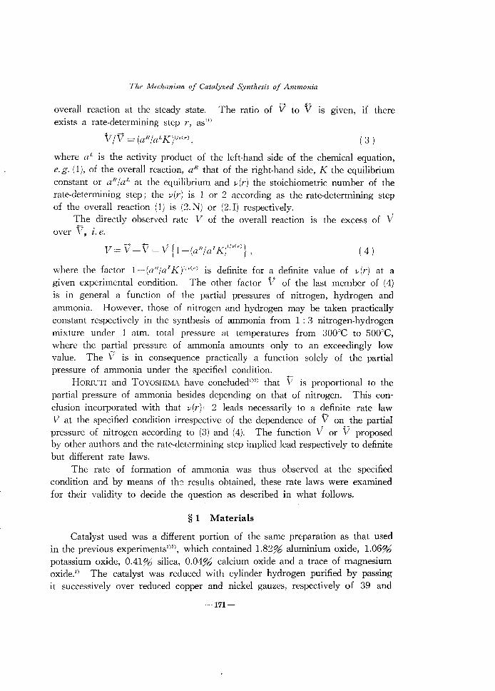
overall reaction at the steady state. The ratio of V to V is given, if there exists a rate-determining step r, as")
(3 )
where a L is the activity product of the left-hand side of the chemical equation, e. g. (1), of the overall reaction, aR that of the right-hand side, K the equilibrium constant or aRia!. at the equilibrium and v(r) the stoichiometric number of the rate-determining step; the v(r) is 1 or 2 according as the rate-determining step of the overall reaction (1) is (2. N) or (2. I) respectively.
The directly observed rate V of the overall reaction is the excess of V over V, l. e.
(4 )
where the factor l_(af?jaI:K)!i'C r) is definite for a definite value of v(r) at a
given experimental condition. The other factor V of the last member of (4) is in general a function of the partial pressures of nitrogen, hydrogen and ammonia. However, those of nitrogen and hydrogen may be taken practically constant respectively in the synthesis of ammonia from 1 : 3 nitrogen-hydrogen mixture under 1 atm. total pressure at temperatures from 300°C to 500°C, where the partial pressure of ammonia amounts only to an exceedingly low value. The V is in consequence practically a function solely of the partial pressure of ammonia under the specified condition.
HORIUTI and TOYOSHIMA have concluded!)') that V is proportional to the partial pressure of ammonia besides depending on that of nitrogen. This conclusion incorporated with that v(r)=2 leads necessarily to a definite rate law V at the specified condition irrespective of the dependence of V on the partial pressure of nitrogen according to (3) and (4). The function V or V proposed by other authors and the rate-determining step implied lead respectively to definite but different rate laws.
The rate of formation of ammonia was thus observed at the specified condition and by means of the results obtained, these rate laws were examined for their validity to decide the question as described in what follows.
§ 1 Materials
Catalyst used was a different portion of the same preparation as that used in the previous experiments')'!, which contained 1.82% aluminium oxide, 1.06% potassium oxide, 0.41% silica, 0.04% calcium oxide and a trace of magnesium oxide.') The catalyst was reduced with cylinder hydrogen purified by passing it successively over reduc:ed copper and nickel gauzes, respectively of 39 and
-171-

Journal of the Research Institute for Catalysis
31 em' apparent volumes and kept both at 600°C, through four columns of silica gel and then over phosphorus pentoxide.
The gas mixture of 1 : 3 nitrogen-hydrogen was prepared by decomposing cylinder ammonia dried over soda lime and solid potassium hydroxide, over the synthetic catalyst kept at 600-700°C and passed through a purification train, which consisted of a wash bottle of conc. sulfric acid solution, a column of
lRs)
Rs
G
Fig. 1. Apparatus for reduction of catalysts.
C: Circulation pump Db D.: Drying agents (silica gel) F: Flow meter G: Gas holder M: Manometer
I-r-vacuum
M
[R,,]: Reaction chamber packed with the catalyst Rt for decomposition [Rs]: Reaction chamber packed with the catalyst Rs for synthesis T" T.: Traps immersed in liq. nitrogen
-172-

The Mechanism of Catalyzed Synthesis of Ammonia
solid sodium hydroxide, a trap immersed in liquid nitrogen, a converter of 42 g copper gauze kept at 600°C, that of 11 g nickel gauze kept at the same temperature and two columns of silica gel, for removing undecomposed am mom a, carbon dioxide, moisture, oxygen and carbon monoxide.
§ 2 Reduction of catalyst
Fig. 1 illustrates schematically a separate apparatus for reducing the catalyst Rd for decomposition of ammonia mentioned and the catalyst Rs for the synthesis experiment in question, which are respectively of 105 and 88.5 g weights and 69 and 48.2 cc apparent volumes before reduction, each packed in the quartz reaction chamber [R,zJ or [RsJ provided with two taps at its both ends. These catalysts are reduced simultaneously by circulating hydrogen purified as described in § 1, by means of the circulation pump C in the direction of arrows, at the 1500 cc/min flow rate first for 202 hours at 300°C, now for 260 hours at 350°C, then for 173 hours at 400°C and finally for 571 hours at 550°C. Water formed by reduction is removed by the columns DI and Dz of silica gel and the traps TI and Tz immersed in liquid nitrogen. The progress of reduction is followed roughly by the decrease of hydrogen pressure on the manometer M. The reduction is continued until the fresh condensation overnight of water in the preliminarily cleaned trap*) TI or Tz is imperceptable. The reaction chambers [RdJ and [RsJ are now closed up each by the taps attached and removed from this apparatus to be built in that for the experiment.
§ 3 Apparatus for synthesis
The apparatus for the synthesis experiment is shown in Fig. 2. The reaction chamber [RaJ, in which the catalyst bed R. is packed and reduced as described in § 2, is of 1 m length and 3.5 cm inner diameter; quartz wool, porcelain Raschig rings and quartz fragments of 8-10 mesh are packed above and below R. as shown in Fig. 2 in order to support it, to preheat the gas mixture entering the catalyst bed and to keep the temperature inside homogeneous. The quartz reaction chamber [RdJ is similarly packed but without the quartz fragments. The temperature of the catalyst bed is measured by alumel-chromel thermojunctions J 1 and J z , calibrated at the melting points of tin, lead, zinc, cadmium and antimony. The thermojunctions J 1 and Jz slide each through a quartz blind tube of 2 mm external diameter fitted, as shown in Fig. 2, just inside the wall or along the axis respectively of the reaction
*) The trap is cleaned by closing it to the catalysts and opening to the vacuum by a proper manipulation of taps.
-173--

1 I
Journal of the Research Insti1ute for Catalysis
_QllllrUwool
--eaUlyst Rs
--Resch'q I"ll'Iqs
OU.,tl "o01
D, etc.: Drying agents D , : Soda lime+pofassium hydroxide D 2 : Soda lime D3: Potassium hydroxide D. : Sodium hydroxide Ds: Silica gel
P r : Pressure regulator (gas overflow) F" F,: Flow meters G: Gas holder Rrz: Reaction chamber packed with the catalyst
Rd for decomposition . Rs: Reaction chamber packed with the catalyst
Rs for synthesis M: Manometer Cu, Ni: Converters packed with reduced copper
or reduced nickel A: Cone. sulfric acid solution T: Trap immersed in liq. nitrogen
Fig. 2. Apparatus for ammonia synthesis experiments.
chamber. The J, is automatically kept at the desired temperature by means of a potentiometric thermoregulator,within +2°C except when otherwise remarked. Pr is the gas overflow for keeping the gas pressure constant at 1 atm. pressure in the apparatus. D
" D" D3 , D, and Ds are the towers of
drying agents. F, and F2 are flowmeters for measuring the flow rates of ammonia and of gas mixture respectively. The temperature of F2 is kept constant at 12°C in a bath of tap water. The wash bottle A contains conc. sulfuric acid solution for removing undecomposed ammonia from the gas mixture.
§ 4 Procedure of experiment
The 1: 3 nitrogen-hydrogen gas mixture was allowed to flow at a constant flow rate through Rs at a constant temperature until a steady synthesis of ammonia was attained in each run conducted in series. The series was begun by raising the temperature of the catalyst bed R8 to that of first run of the series under the constant inflow rate of nitrogen-hydrogen mixture. Two hours after the temperature was attained, the outflow rate NA of ammonia was begun to be
-174-

The Mechanism of Catalyzed Synthesis of Ammonia
measured repeatedly, until it attained a constant value. One to three runs were conducted usually per day switching from one to the other constant flow rate or temperature. On closing the daily work, R. was allowed to cool in the nitrogen-hydrogen mixture down to room temperature and kept in the gas mixture overnight. The daily work was initiated just as in the beginning of the series.
The NA was determined by passing the gas mixture through sulfuric acid solution of known concentration and quantity for a recorded time and by titrating the solution back.
TABLE 1. Experimental Results
I Temperature °C 1 Inflow rate of I Outflow rate No. of;
I
I I I N ,-H,-mixturel NA of NHa
runs I t, t, t, t. t5 t. !(average! cc NTP/hr. cc NTP/hr. I
1 301 301 301 301 I 300 300 I 301 63600 I 5.16
,
2 301 301 301 I 300 . 300 300 , 301 79200 5.94
3*) 298 297 297 I 304 303 3031
300 94200 6.18 ±0.22
4 302 302 302 300 300 300 301 106800 6.12 ±0.33 15 303 302 301 I 308 303 302 303 188400 5.22 ±0.21
5 353 353 353 354 354 i 354 I 354 ! 51600 14.76 ±0.37
6 354 354 354 ! 353 353 353 , 354 103200 20046
16 353 353 353 357 357 357 355 178800 14.G4 ±Oo41 17*) ! 355 355 . 355 I 360 356 354 356 249000 18.78 ±0.47
7 406 406 403 403 403 403 404 79200 48.84
8 ! 403
1
403 ! 403 401 401 401 i 402 117600 62.22
9 404 404 404 • 405 405 405 I 405 55800 44.40
18 405\ 403 I 400 I 408 4041
402 ' 404 261600 58.68
22 403 403 403 407 406 405 405 61800 41.28
10 457 457 457 458 458 458 458 63600 102.90
11*) 459 458 458 454 454 454 456 ! 120600 171.6
12) 456 457 457 458 458
::: I
458 82800 121.86
13 458 458 : 458 456 456 457 58200 99.36
14 4631
460 453 460 458 452 458 I 273600 247.8 I
19 459 . 458 • 457 457 456 452\ 457 174000 164.28
20 458 458 458 458 458 458 458 79200 111.72
21 457 457 457 460 460 460 ! 459 66000 99.36 I
* ) Temperature fluctiation in these runs is kept within ±4°C, whereas that in other runs within ±2°C.
**) The probable relative errors of N·! are within 1.6;?~ unless otherwise stated.
-175-

Journal of the Research Institute for Catalysis
§ 5 Experimental results
The experimental results are shown in Table 1. No. of runs shows the order of runs, in which they have been conducted sporadically at different temperatures, in order to keep check with the activity of the catalyst. Temperatures t1, t2 and t3 are those read at the top, middle and bottom along the axis of Rs respectively and t" t5 and t6 are those read respectively at the corresponding possition on the wall. Ammonia outflow rate, N A , given in Table 1 is the average value of the several measurements at the steady state for each run, its probable relative error being within 1.6% unless otherwise stated.
§ 6 Analysis for the rate of synthesis
The rate 17 of ammonia synthesis was determined in cc NTP of ammonia synthesized per hr per cc of the catalyst bed by analyzing the steady rate NA of ammonia formation under the following premises:
( I) The flow of gas components and the conversion among them are steady everywhere in Rs.
(II) The temperature and the flow rate of every gas component are homogeneous over any cross section of R,.
(III) The mol fraction x" of a gas component 0 equals its fraction of the flow rate.
(IV) The temperature is homogeneous along the axis of Rs. We have immediately from (1) and the premise (I)
nA = 2 (ni:-n N) = (2/3) (n'{-nIf) , (6.1)
where n° is the flow rate of gas component 0 across a horizontal section of R s , n~ that at the inlet and the superffix A, Nand H specify the gas components 0 for ammonia, nitrogen and hydrogen respectively. From the premise (III) the mol fraction x A of ammonia at the horizontal section is glven as
x A = nA/(nA + n N + nIf) .
Eliminating n N and n R from (6.1) and (6.2), we have
x A = nA/(no-nA) ,
or
where
N R no = no + no .
-176-
(6.2)
(6.3. a)
(6.3. b)

The Afechanism of Catalyzed Synthesis of Ammonia
The overall rate V is now homogeneous over any horizontal section of Rs as a function of temperature and concentrations x' of components. The increment dnA of the steady flow rate of ammonia through a horizontal section with the shift dh of the section along the direction of the flow is gIven as
dnA = VSdh , (6.4)
where S is the area of the section. We have, hence, by (6.3. a)
nodxA/(l +XAy = VSdh (6.5)
or by integration ,A f' dxA/(l +XAy V = V/llo , (6.6)
where v is the total volume of the catalyst bed and x1 IS the mol fraction of ammonia m the outflow gas.
§ 7 Rate equation of ammonia synthesis
It was concluded by TOYOSHIMA and HORIUTI')2) as mentioned in the introduction that the rate-determining step of decomposition of ammonia was (2. I) and that the unidirectional rate V of decomposition was proportional to the ammonia partial pressure besides depending on the partial pressure of nitrogen. Under the present experimental condition, where the partial pressures of nitrogen and hydrogen are kept practically constant, V must then be a sole function of the partial pressure of ammonia, the former being directly proportional to the latter.
The forward unidirectional rate V is determined as follows. The righthand side of (3) is developed as
(a"/a~ K),/v(r) = {(a A/a:)2 (aIf/all) 3 (a;V/aN)} '/v(,')
noting that
(7.1)
where a A etc. are activities of ammonia etc. and suffix e signifies the quantities at equilibrium as in what follows. We have, admitting the propotionality of the activities respectively to the relevant partial pressures pA etc.,
(a"/aLKjIMr) = {(PA/P:)2(P~/PEJ3(PeVIPV)} liver)
or identifying p3 and pv with Peg and P;v because of the practical constancy of pH and pv
(a"/aLK)'f>(,) = (PA/P;,?Jv(,) .
-177-
(7.2)
Journal of the Research Institute for Catalysis
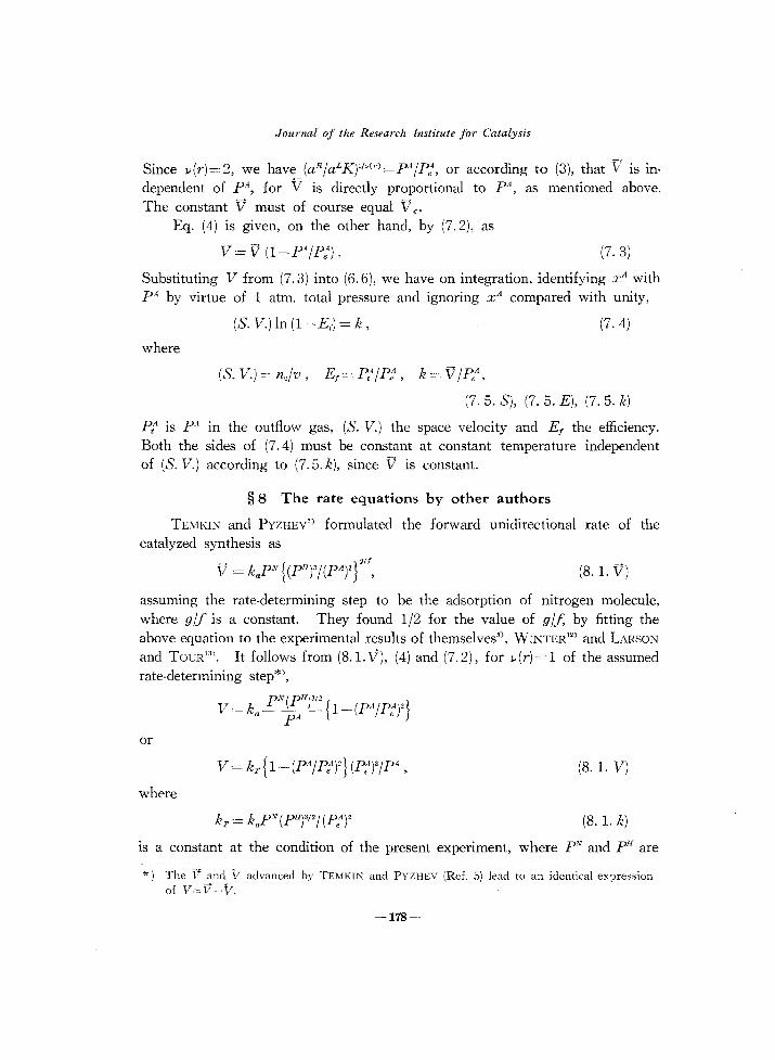
Since lJ(r)=2, we have (aRjaLK)lM'l=pAjPe\ or according to (3), that V IS In
dependent of P\ for " is directly proportional to pA, as mentioned above. The constant V must of course equal Ve.
Eq. (4) is given, on the other hand, by (7.2), as
V = V (I_PA jP:). (7.3)
Substituting V from (7.3) into (6.6), we have on integration, identifying x A with pA by virtue of 1 atm. total pressure and ignoring x A compared with unity,
-(5. V.) In (I-Ej ) = k, (7.4)
where
(S.V.)=nojv, Ej=P,AjPeA
, k=VjPeA,
(7.5. S), (7. 5. E), (7.5. k)
Pt is pA in the outflow gas, (S. V.) the space velocity and E j the efficiency. Both the sides of (7.4) must be constant at constant temperature independent of (S. V.) according to (7.5. k), since V is constant.
§ 8 The rate equations by other authors
TEMKIN and PYZHEV'} formulated the forward unidirectional rate of the catalyzed synthesis as
}
Olj
V = kaY' {(pH)3j(PA)2 , (8.1. V)
assuming the rate-determining step to be the adsorption of nitrogen molecule, where gjf is a constant. They found Ij2 for the value of gjf, by fitting the above equation to the experimental results of themselves'}, WINTER l2
) and LARSON and TOUR13). It follows from (8.1.V), (4) and (7.2), for lJ(r)=1 of the assumed rate-determining step*),
PN(PH )3/ 2 V = ka p A {1_(PAjP:)2}
or
(8.1. V)
where
(8.1. k)
IS a constant at the condition of the present experiment, where PV and pH are
*) The V and 17 advanced by TEMKIN and PYZHEV (Ref. 5) lead to an identical expression of V==V-V.
-178-

The Mechanism of Catalyzed Synthesis of Ammonia
practically constant. Substituting V from (S.1. VJ into (6.6), we have by a similar integration to that in § 7
-(So V.)ln(l-E;)=kr.
LOVE and EMMETT'l, on the other hand, concluded that
V = k2(PA)"'60/(PH)"'85
(S.2)
(S.3)
from their experimental result on the decomposition of ammonia in the presence of doubly promoted iron catalyst (No. 931), hence that the rate·determining step was (2.1). It follows from (3), (7.2) and (S.3), putting lJ(r)=l for the concluded rate-determining step, that
where
k, = k2(P:Y(PI1-o.85 .
The V = V - V is expressed by (S.4) and (S.3) as
V=k,(PA)-1·40{1_(PA /P:)2} .
(S.4. V)
(8.4. k)
Substituting V from the above equation into (6.6) and intergrating similarly as above, noting that k, as given by (S. 4. k) is practically constant at the present experimental condition, we have
(8.5)
where
§ 9 Examination of the rate equation
The rate equation (7.4) is now examined for its validity with regard to the premises (I), (II), (III) and (IV) in § 6, on which it is based.
We may take (I) for granted on the ground of sufficiently steady value of NA as observed and (II) too, as supported by the practical coincidence of the observed temperatures at the every horizontal section through the catalyst bed as seen from Table 1. It is inferred in the previous analysis') that (III) holds practically exactly at linear flow rate of gas above 0.06 em/sec, which is amply satisfied at the present experimental series conducted at the linear flow rates above 3.5 em/sec.
The premise (IV) is also practically satisfied within experimental errors of temperature determination except in a few runs as seen in Table 1. The value
-179-

Journal of the Research Institute for Catalysis
k m of k at a specified temperature T", supposed to be kept constant throughout the catalyst bed was evaluated as detailed in Appendix from the experimental result of run 14, admitting the premises (I), (II) and (III) but allowing for the temperature variation along the axis of the catalyst bed. The value of k", thus obtained for T m =731°K from the experimental results of run 14 is shown in parentheses in Table 2. The k-value given right above for the same run is, similarly to other k-values given in the Table, that calculated by (7.4) assuming the validity of (IV) at the average temperature of t,," ·t., which is identical with the above value of Tnt. The approximate value 'of k thus obtained differs from k,n only by less than 1%. It may safely be taken that k in other cases calculated similarly by (7.4) is accurate enough in this regard, the variation of temperature along the axis being much smaller than in run 14 as seen from Table 1. No detailed examination of this sort has been tried for other constants kr etc. expecting that the similar would be the case.
§ 10 Constancy of the rate constants
The values of kr and kE are calculated by (8.2) and (8.5) as shown in Table 2 side by side with k-values computed by (7.4). The values of PeA are calculated by the empirical equation of the equilibrium constant of the ammonia synthesis reaction given by GILLESPIE and BEATTIE"). The efficiency Ef is evaluated by (7.5. E), identifying PtA with the fraction NAlno of the flow rate of ammonia on the ground of (III), § 6 and of the one atm. total pressure at the present experiment. As shown in the columns 6, 7 and 8 of Table 2, k
is appreciably constant at the respective constant temperatures with the average deviations of from 5.5 to 14.5%, whereas kr and kE varies by a factor of from 2 to 6. The k-value indicates, moreover, a considerable reproduciblility of the activity of the one and the same catalyst sample used, with reference to the numbers of runs scattered sporadically over different temperatures.
§ 11 Discussion
ENOMOTO and HORIUTI3) have previously shown that the rate V of the
catalyzed synthesis of ammonia near equilibrium is proportional to P: - p A at the experimental condition, where the partial pressures of nitrogen and hydrogen are kept practically constant as in the present case and that the appropriate proportionality constant, r, = VI (Pe4_PA
) is given as r,=2V e!))(r)P:. They have determined r, at different temperatures from 400°C to 445°C from the observed increase or decrease of ammonia partial pressure with time in the presence of the catalyst of the same preparations as used in the present experiment, hence
-180-

The Mechanism of Catalyzed Synthesis of Ammonia
TABLE 2. The rate constants of ammonia synthesis from the present experimental results.
Tempera- P,,1 atm. No. of I (S. V.J ture I cc NTP ,
I ' , k I kr I cc NTP, cc NTP
kE ccNTP
cc cat. hr. 'C >< 102 runs, cc cat. hr. 1 i cc cat. hr.! cc cat. hr~ ._---- -----------------
301 1.89
355 0.777
404 0.384
458 0.195
2
3
4
15
5
6
16
17
7
8
9
18
22
10
11
12
13
14
19
20
21
1320
1644
1955
2218
3910
1070
2140
3710
5170
1644
2440
1158
5430
1282
1320
2500
1717
1208
5680
3610
1644
1370
4.2 x1O- 3
4.0 X 10- 3
3.47 X 10- 3
3.08x1O- 3
1.5 X 10- 3
5.56
6.60
6.78
6.72
5.87
3.68 ;<10 - 2 40.1
2.55 >< 10- 2 55.2
1.01)< 10-' 37.6
0.971 X 10' 2 50.2
0.161 288
0.138 353
0.207 269
0.0584 326
0.174 245
0.830 2340
0.729 3270
0.756 2420
0.875
0.464
0.484
0.723
0.773
2520
3550 (3530) 2390
2110
2030
2.33x1O- 2 1.10 x10- 3
2.63><10-' 1.19 xl0- 3
2.35x10-' 1.00 xlO- 3
2.03xl0-' 0.862><10- 3
0.90><10. 2 0.270 X 10- 3
1.45
1.39
0.378
0.487
43.2
46.9
50.6
18.6
49.3
1530
1900
1450
1760
1370
960
1210
1250
0.162
0.135
0.225
0.0304
8.60
8.96
11.0
2.48
8.20
623
715
560
898
427
304
459
486
found that RT'd In r1/dT= 33 KcaI. It follows from the preceding expression of r 1 and (7.5. k) that r 1 varies with temperature proportional to k, inasmuch as V in (7.5. k) equals Ve as mentioned in § 7. Therefore, RT2d In k/dT is required to be identical with RT'd In r1/dT, provided that the reaction (1) were followed consistently both in the cases. RT'd In k/dT is now 31.9+ 1.1 Kcal as determined from the values of k at different temperatures in Table 2, which agrees satisfactorily with the above value of RT2d In r1/dT, fulfilling the requirement.
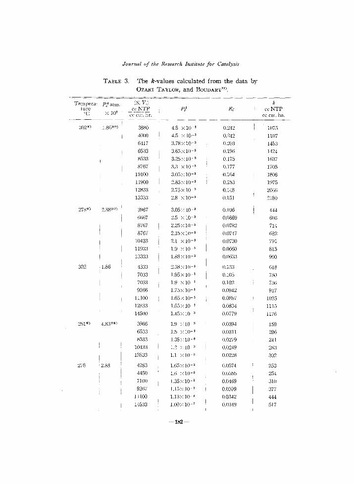
Table 3 shows the k-value calculated from the recent data of OZAKI, TAYLOR and BOUDART15
) by (7.4), which is not as constant as that from the present experiment. Both the series of experiments have been carried out under almost the same experimental condition in the presence of the same sort
-181-
Journal of the Research Institute for Catalysis
TABLE 3. The k-values calculated from the data by OZAKI TAYLOR, and BODDART15
).
Tempera' P1 atm. (S. V.l k ture ccNTP pt1 Ef ccNTP
'C x 10' cc-cat:11r. cc cat. ha.
302*) 1.86*") 3880 4.5 x 10- 3 0.242 1075
4000 4.5 x 10⁻³ 0.242 1107
6417 3.78xlO- 3 0.203 1453
6533 3.65xlO- 3 0.196 1424
8533 3.25x 10- 3 0.175 1637
8767 3.3 x 10- 3 0.177 1705
10100 3.05 ><10- 3 0.164 1806
11900 2.85xl0-3 0.153 1975
12833 2.75xl0-3 0.148 2066
13333 2.8 x 10⁻³ 0.151 2180
278*) 2.88*") 3967 3.05 x 10- 3 0.106 444
6667 2.5 X 10- 3 0.0869 606
8767 2.25>~ 10- 3 0.0782 714
8767 2.15x 10- 3 0.0747 682
10433 2.1 X 10- 3 0.0730 791
11933 1.9 ;( 10- 3 0.0660 815
13333 1.88>~ 10- 3 0.0653 900
302 1.86 4333 2.38>c 10- 3 0.133 618
7033 1.95>c 10- 3 0.105 780
7033 1.9 x 10- 3 0.102 756
9266 1.75>c 10- 3 0.0942 917
11100 1.65 X 10- 3 0.0887 1025
12833 1.55 >( 10- 3 0.0834 1115
14500 1.45>c 10- 3 0.0779 1176
251*) 4.83**) 3966 1.9 >c1O- 3 0.0394 159
6533 1.5 )~ 10- 3 0.0311 206
8533 1.35); 10- 3 0.0279 241
10433 1.2 >c10- 3 0.0249 263
i 12833 1.1 >c 10- 3 0.0228 302
278 • 2.88 4283 1.65)( 10- 3 0.0574 253
4450 1.6 )( 10- 3 0.0555 254
7100 1.35><10- 3 0.0469 310
9267 1.15)( 10- 3 0.0399 377
11100 1.13 x 10- 3 0.0342 444
14533 1.00>c 10-3 0.0349 517
-182-
The Mechanism of Catalyzed Synthesis of Ammonia
Tempera- P:atm. (S. V.) k ture ~ ccNTP P? Ef ccNTP °C x 10' cc cat. hr. cc cat: hr.
251 4.83 4283 1.0 xlO- 3 0.0207 89.6
4450 0.95x 10- 3 0.0197 88.2
7233 0.8 x 10- 3 0.0166 121
9267 0.7 X 10- 3 0.0145 135
9533 0.7 >< lO~ 3 0.0145 139
11500 0.65x 10- 3 0.0135 156
12833 0.62x 10- 3 0.0128 165
14833 0.59xlO- 3 0.0122 182
218*) 9.33*") 6666 0.61 X 10- 3 6.54 xlO- 3 49.0
10400 0.49 X 10- 3 5.25 )( 10- 3 55.0
13333 0.43 X 10- 3 4.61 X 10- 3 62.3
302") ; 1.86**) 1757 5.5 xlO- 3 0.296 617
2383 4.8 X 10- 3 0.258 712
3750 3.95x 10- 3 0.212 893
4900 3.55>( 10- 3 0.191 936
6960 3.05x 10⁻³ 0.164 1245
302 1.86 1907 2.80xlO- 3 0.151 312
2467 2.55x 10- 3 0.137 363
2467 2.5 X 10-. 3 0.135 357
4067 2.15x 10- 3 0.116 502
5367 1.85 ><10- 3 0.0995 563
7767 1.63)( 10· 3 0.0874 710
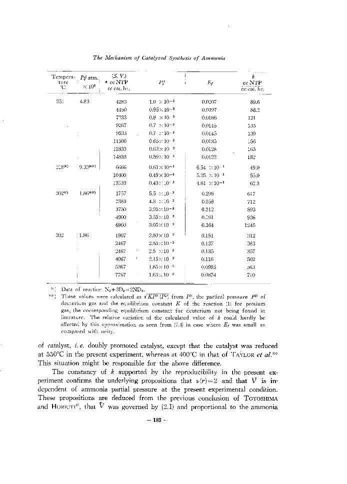
*) Data of reaction N,+3D2 =2ND3 •
**) These values were calculated as I KP" (pO) from r', the partical pressure pD of deuterium gas and the equilibrium constant K of the reaction (1) for protium gas, the corresponding equilibrium constant for deuterium not being found in literature. The relative variation of the calculated value of k could hardly be affected by this approximation as seen from (7.4) in case where Ef was small as compared with unity.
of catalyst, i. e. doubly promoted catalyst, except that the catalyst was reduced at 550°C in the present experiment, whereas at 400°C in that of TAYLOR et aZ-'5) This situation might be responsible for the above difference.
The constancy of k supported by the reproducibility in the present experiment confirms the underlying propositions that J.i(r)=2 and that V is independent of ammonia partial pressure at the present experimental condition. These propositions are deduced from the previous conclusion of TOYOSHIMA and HORIUTI2
), that V was governed by (2.1) and proportional to the ammonia
-183-

Journal of the Research Institute for Catalysis
partial pressure, which was arrived at from the experimental result with the catalyst of the same preparation as that of the present experiment.
The latter group of authors concluded besides that V depends on the partial pressure of nitrogen as mentioned in the introduction. This conclusion is beyond the scope of present investigation, where the partial pressure of nitrogen is practically fixed. However, LOVE and EMMETT') have concluded from the observed indifference of catalyzed decomposition rate of ammonia to the diluent either of nitrogen or of helium, that the rate of controlling step of the decomposition is unaffected by the nitrogen partial pressure. These conflicting conclusions will be the subject of our further investigations.
Summary
(1) The 1: 3 nitrogen-hydrogen mixture was allowed to flow through the bed of doubly promoted iron catalyst at 1 atm. total pressure and at different temperatures from 301 to 458°C. The catalyst was reduced at temperature raised stepwise up to 550°C. The ammonia outflow rate, hence the efficiency Ef of ammonia formation was determined at each constant temperature for different space velocity (s. V.) ranging from 1000 to 5700 cc NTP/cc catalyst hr.
(2) The rate equation - (s. V.) In (I-Ef ) =k of ammonia synthesis, where k is constant independent of (S. V.) at constant temperature, was deduced from the premises A) that partial pressures of nitrogen and hydrogen are respectively constant and B) that the stoichiometric number of the rate-determining step is 2 and the unidirectional decomposition rate of ammonia is proportional to its partial pressure. The premise A) was practically realized experimentally, whereas B) was derived from the previous conclusion of ENOMOTO, HORIUTI and KoBAYASHI')') and HORIUTI and TOYOSHIMA').
( 3 ) The rate constant k was found to be remarkably reproducible and constant over the range of space velocity mentioned at the respective constant temperatures, whereas the similar constants as required by other rate laws varied considerably.
(4) The activation energy RT'dlnk/dT was found to be 31.9+1.1 Kcal, which was in excellent agreement with that 33 Kcal derived from independent
measurements by ENOMOTO and HORIUTI') with the catalyst of the same preparation.
( 5 ) These results verify the previous conclusions of HORIUTI and ToyoSHIMA2
) underlying the rate equation mentioned in (2), that the rate-determining step of the catalyzed decomposition of ammonia was the step of the decomposition of adsorbed imino group and that the unidirectional rate of decomposition
-184-

The Mechanism of Catalyzed Synthesis of Ammonia
was proportional to the partial pressure of ammonia. The authors wish to thank Dr. Isamu TOYOSHIMA for his valuable advices.
Their thanks are also due to the Grant in Aid for Fundamental Scientific Research of the Ministry of Education.
References
1) ]. HORlUTI and 1. TOYOSHIMA, this Journal, 5, 120 (1957).
2) ]. HORlUTI and 1. TOYOSHIMA, ibid. 6, 68 (1958).
3) S. E="OMOTO and ]. HORlUTI, Proc. Japan Acad., 28, 493, 499 (1952), this Journal,
2, 87 (1953).
4) S. E="OMOTO, ]. HORIUTI and H. KOBAYASHI, ibid. 3, 185 (1955).
5) M. TEMKIN and V. PYZHEV, Acta Physicochimica, USSR, 12, 327 (1940).
6) P. H. EMMETT and ]. T. KUMMER, Ind. Eng. Chern., 35, 677 (1933).
7) K. S. LOVE and P. H. EMMETT, ]. Am. Chern. Soc., 63, 3297 (1941).
8) R. BRILL, ]. Chern. Phys., 19, 1047 (1951).
9) W. G. FRANKENBURG, Catalysis Vol. III, 171 (1955), Reinhold Publishing Corporation.
C. BOKHOVEN, C. VAN HEERDEN, R. WESTRIK and P. ZWIETERING, ibid. 265
(1955).
10) J. HORlUTI and 1. TOYOSHIMA, "Mechanism of catalyzed synthesis of ammonia"
presented to the Eighth MENDELEJEF Conference, Moscow, March 16-23, 1959. in the
press.
11) ]. HORlUTI, this Journal, 1, 8 (1948), ibid., 5, 1 (1957), Proc. Japan Acad., 29, 160
(1953), Advances in Catalysis 9, 339 (1957), The problems of physical chemistry, 2, 39
(1959), GOSCHIMIZDAT (Moscow.).
12) E. WINTER, Z. phys. Chern., B 13, 401 (1931).
13) A. T. LARSON and R. S. TOUR, Chern. and Met. Eng., 26, 647 (1922).
14) L.]. GILLESPIE and]. A. BEATTIE, Phys. Rev., 36, 743 (1930).
15) A. OZAKI, H. S. TAYLOR, and M. BOUDART, Proc. Royal. Soc., 258, 47 (1960).
-185-

Journal of the Research Institute for Catalysis
APPENDIX
The value k m of k, which would be obtained at Tn, = 731 0 K supposed to be kept constant over the catalyst bed, was worked out as follows, allowing for the variation of temperature along the axis of the catalyst bed, on the basis of the premises (I), (II) and (III) particularly for run 14 shown in Table 2.
Identifying x A with p A but ignoring it as compared with unity as in the text, we have from (6.5)
nodpA = VSdh,
or substituting V from (7.3)
nodpA = V (I-PA/PeA) Sdh. ( i )
The f! III (i) is given as a function of temperature as
(ii. a)
where
E= 19.3+1.1 Kcal. (ii. b)
Eq. (ii) was deduced, according to (7.5. k), from k-values at different temperatures as determined by (7.4) without allowing for the temperatures variation along the axis and from the known function P; of temperature, z. e.
where
ilH = -12.6 Kcal, Pe,m = 0.195 X 10⁻² atm
(iii. a)
for T m =731°K;
(iii. b), (iii. c)
(iii) was derived for 1 atm. total pressure from the equilibrium constant given by GILLESPIE and BEATTIE").
The temperature along the axis of the catalyst bed is given by experiment as a function of h, hence V and P; are given as functions of h according to (ii) and (iii); the differential equation (i) is in consequence integrated to give V", as a function of the value P/ of pA at the outlet. The value of Pm is thus determined by the directly observed value of P;4. The value of k,n in question is now given by (7.5. k) as
(iv)
Practically the above calculation has been carried out as follows by introducing the independent variable I, i. e.
-·186-

The lWechanism of Catalyzed Synthesis oj Ammonia
l = h/H, (v)
where H is the height of the catalyst bed. V and p~4 are now known functions of l, since they are given as known functions of h as mentioned above; the differential equation (i) is hence written in the form
~ dPi(jl+_y'J!l P4(l)-V(l):= 0 SH dl pe4 (l) ,
which IS integrated as
A J' JI SH ,til) SH ~ Pt = exp ( ~ -:4-- dl) ~ V (l)dl , o ,no P e (l) no
(vi)
referring to the boundary condition that p1=0 at l=O. by developing l as
The integral is evaluated
l:= a +b/T+c/T2, (vii. a)
where the constants a, band c are fitted to the experimental data of run 14 in question, i.e. (t3 +t6 )/2=452Sc at l=O, (t2 + t s/)2 = 459°C at 1=1/2 and (t,+t,)/2=461Sc at 1:=1, as
as
a = 7.490437 x 10³, b= -1.087609 X 10', c=3.948013 X 10' (vii. b)
The integral JI vY) dl in (vi) is carried out by (vii. a), (ii. a) and (iii. a) , Pe (l)
JI ft(l) ft (E- AH [ R I JH-,"( 2 JH-r:( 2 1 -A- dl = --p- exp iJ) , _ e--;U b + _~ ) - e JUt b + _ C)
, Pe (l) Pe _", RTm LlH-E 1 T, T, J
+2(' R )2c(eJ~-:r~ _/;,-:)] LlH-E '
(viii)
where T, is the particular value of T at l = 1. The integrand of (vi) is now plotted against 1 with T as a parameter with reference to (ii. b), (iii. b), (iii. c), (vii. b) and (viii) for a trial value of V m at T m = 731 0 K. The graphical integration of (vi) yields a trial value of P; relevant to that of V m" It is thus found that the value 6.87 cc NTP/cc cat. hr of V m fits in with the observed value of P/ given in Table 2, i. e.
P,l = 9.06 X 10-' atm.
The km-value of run 14 given in the parentheses of Table 2 IS obtained from the above value of V,n by (iv) and (iii. c).
-187-