the manyears open framework -...
TRANSCRIPT

Auton Robot (2013) 34:217–232DOI 10.1007/s10514-012-9316-x
The ManyEars open frameworkMicrophone array open software and open hardware system for robotic applications
François Grondin · Dominic Létourneau ·François Ferland · Vincent Rousseau ·François Michaud
Received: 28 May 2012 / Accepted: 29 December 2012 / Published online: 2 February 2013© Springer Science+Business Media New York 2013
Abstract ManyEars is an open framework for microphonearray-based audio processing. It consists of a sound sourcelocalization, tracking and separation system that can providean enhanced speaker signal for improved speech and soundrecognition in real-world settings. ManyEars software frame-work is composed of a portable and modular C library, alongwith a graphical user interface for tuning the parameters andfor real-time monitoring. This paper presents the integra-tion of the ManyEars Library with Willow Garage’s RobotOperating System. To facilitate the use of ManyEars on var-ious robotic platforms, the paper also introduces the cus-tomized microphone board and sound card distributed as anopen hardware solution for implementation of robotic audi-tion systems.
Keywords Open source · Sound source localization ·Sound source separation · Mobile robotics · USB soundcard · Open hardware · Microphone array
F. Grondin · D. Létourneau · F. Ferland · V. Rousseau · F. Michaud (B)IntRoLab – Intelligent, Interactive, Integrated Robotics Lab,Interdisciplinary Institute for Technological Innovation Université deSherbrooke, 3000, boul. de l’Université, Sherbrooke,QC J1K 0A5, Canadae-mail: [email protected]
F. Grondine-mail: [email protected]
D. Létourneaue-mail: [email protected]
F. Ferlande-mail: [email protected]
V. Rousseaue-mail: [email protected]
1 Introduction
Autonomous robots must be able to perceive sounds fromthe environment in order to interact naturally with humans.Robots operate in noisy environments, and limitations areobserved in such conditions when using only one or twomicrophones (Wolff et al. 2009). In that regard, a micro-phone array can enhance performances by allowing a robotto localize, track, and separate multiple sound sources.
Using an array of eight microphones, ManyEars(Valin et al. 2006a,b, 2003) demonstrated that it can, simul-taneously and in real-time, reliably localize and track up tofour of the loudest sound sources in reverberant and noisyenvironments (Valin et al. 2006b). ManyEars can also reli-ably separate up to three sources in an adverse environmentwith a suitable signal-to-noise ratio improvement for speechrecognition (Yamamoto et al. 2006, 2005). ManyEars needsat least four microphones to operate, and the number ofmicrophones used influences the number of sources that canbe processed. It has mostly been used with arrays of eightmicrophones, to match the maximum number of analog inputchannels on the sound cards used. ManyEars has been usedon different platforms including Spartacus (Michaud et al.2007), SIG2 (Yamamoto et al. 2005) and ASIMO (Yamamotoet al. 2006), and as a pre-processing module for improvedspeech recognition (Valin et al. 2007; Yamamoto et al. 2007,2006, 2005). Many components of ManyEars are also used inHARK (HRI-JP Audition for Robots with Kyoto University)(Nakadai et al. 2010), an open source real-time system thatalso integrates new localization techniques such as GEVDMUSIC (Generalized EigenValue Decomposition MultipleSignal Classification) and GSVD-MUSIC (Generalized Sin-gular Value Decomposition Multiple Signal Classification)(Nakadai et al. 2012; Nakamura et al. 2012; Otsuka et al.2011).
123

218 Auton Robot (2013) 34:217–232
The first implementation of ManyEars and HARK bothrely heavily on FlowDesigner (Létourneau et al. 2005; Valinet al. 2008), an open source data flow development environ-ment used to build complex applications by combining smalland reusable building blocks. To facilitate maintenance andportability, ManyEars is now implemented in C as a mod-ular library, with no dependance on external libraries. Thesource code is available online (Grondin et al. 2012) under theGNU GPL license (Free Software Foundation, Inc. 2012). AGraphical User Interface (GUI) (also available online (IntRo-Lab 2012)) is used to display in real-time the tracked soundsources and to facilitate configuration and tuning of the para-meters of the ManyEars library. This paper presents theseimplementations and their integration to Willow Garage’sRobot Operating System (ROS) (Quigley et al. 2009).
To make use of the ManyEars library, a computer, a soundcard and microphones are required. ManyEars can be usedwith commercially available sound cards and microphones.However, commercial sound cards present limitations whenused for embedded robotic applications: they are usuallyexpensive; they have functionalities such as sound effects,integrated mixing, optical inputs/outputs, S/PDIF, MIDI,numerous analogs outputs, etc., which are not required forrobot audition; they also require significant amount of powerand size. The EAR sensor has been proposed as an alternative(Bonnal et al. 2009), but it remains large and has strong cou-pling with the software which runs on a Field-ProgrammableGate Array (FPGA). With ManyEars, computations are doneon an onboard computer not embedded to the sound card, tofacilitate portability and maintenance. To this end, the paper
also introduces the customized microphone acquisition boardand a 8-input sound card distributed as an open hardwarealternative for robotic audition systems.
The paper is organized as follows. Sect. 2 presents therevised implementation of ManyEars as an open source Clibrary. Sect. 3 introduces the GUI and explains ManyEars’portability by presenting its integration to ROS. Sect. 4describes ManyEars’ open hardware components and Sect.5 presents test cases to illustrate the use of the implementedframework.
2 ManyEars
Figure 1 illustrates the software architecture of ManyEarsLibrary. It is composed of five modules: Preprocessing,Localization, Tracking, Separation and Postprocessing.These modules receive inputs and generate data using theMicrophones, potential sources, tracked sources, separatedsources and postfiltered sources data structures. In the fol-lowing subsections, each of the five modules is described,along with the equations explaining what is implemented inthe code. The parameters provided were set empirically tobe robust to environmental changes, unless mentioned other-wise. More detailed explanations and justifications of theseequations and parameters are available in (Valin et al. 2006b)(Preprocessing, Localization and Tracking) and in (Valin etal. 2004) (Separation and Postprocessing). Also note that inthis section, the variables m, i and k stand for the microphone,the frame and the bin indexes, respectively.
Fig. 1 Software architecture of the ManyEars library
123

Auton Robot (2013) 34:217–232 219
Fig. 2 Block diagram of the preprocessing module
2.1 Preprocessing module
The Preprocessing Module uses a MicST (Microphone Sig-nal Transform) data structure to transform the time-domainsignal of each microphone (sampled at 48,000 samples/sec)in weighted frequency frames, as shown in Fig. 2. The Pre-processor function transforms the microphone signal in thetime domain into many individual frames of N = 1,024 sam-ples. Each frame is multiplied by a power-complementarywindow and then transformed in the frequency domain witha Fast Fourier Transform (FFT), which leads to Xl
m[k]. TheMCRA (Minimum Controlled Recursive Averaging) func-tion is used to estimate the spectrum of the stationary noise(λs)l
m[k] during silence periods (Cohen and Berdugo 2002).The frames are initialized with zero values at frame l = 0in Eq. 1, and then updated recursively. The weighting factorζ l
m[k] is then computed at each frequency bin according toEqs. 2, 3, and 4. The variables ξ l
m[k] and (λr )lm[k] respec-
tively represent the estimation of the a priori Signal-to-NoiseRatio (SNR) and the reverberation estimation (Ephraim andMalah 1984, 1985). The parameter αd = 0.1 is the adapta-tion rate, γ = 0.3 the reverberation decay for the room, andδ = 1.0 the level of reverberation. These parameters need tobe adjusted to the environment.
(λr )0m[k] = 0
(λs)0m[k] = 0
ξ0m[k] = 0
ζ 0m[k] = 0
0 ≤ m < M, 0 ≤ k < N (1)
(λr )lm[k] = γ (λr )l−1
m [k] + (1 − γ )
δ
∣∣∣ζ
l−1m [k]Xl−1
m [k]∣∣∣
2(2)
ξ lm[k] =
(1 − αd)
∣∣∣ζ
l−1m [k]Xl−1
m [k]∣∣∣
2 + αd
∣∣∣Xl
m[k]∣∣∣
2
(λr )lm[k] + (λs)l
m[k] (3)
ζ lm[k] = ξ l
m[k]ξ l
m[k] + 1(4)
Fig. 3 Block diagram of the localization module
2.2 Localization module
Figure 3 illustrates the block diagram of the LocalizationModule. The Microphones data structure contains the carte-sian positions (in meters) for each microphone in relation tothe center of the array. A uniform unit sphere (with a 1 mradius) is generated at the initialization of the Sphere datastructure. This sphere is recursively generated from a tetra-hedron, for a total of 2,562 points. This resolution can beadjusted to satisfy real-time requirements. The delay betweeneach pair of microphones for sound propagation of a source isprecomputed at each point on the sphere during initializationof the Delays data structure, and stored in an array. Each delaycorresponds to the direct path of sound, even if this hypoth-esis is influenced by the diffraction due to the body of therobot. However, experiments show that the system still per-forms well as long as a few microphones capture the directpath (Valin et al. 2006b). The cross-correlation Rl
m1,m2(τ )
between microphones m1 and m2 is then computed for eachnew frames according to Eq. 5, with τ representing the delay.
Rlm1,m2
(τ ) =N−1∑
k=0
ζ lm1
[k]Xlm1
[k]|Xl
m1[k]|
ζ lm2
[k]Xlm2
[k]∗|Xl
m2[k]| e
(j2πkτ
N
)
(5)
To speed up computations, Eq. 5 is performed withan inverse Fourier Transform (IFFT). Although the IFFTreduces the number of operations, this step remains one ofthe most computationally expensive part of ManyEars. More-over, since this operation is done for each pair of micro-phones, the complexity order is O(M(M − 1)/2), where Mis the number of microphones.1 Beamformer search is per-formed (Valin et al. 2006b) and implemented in the Beam-former function. Once Q potential sources are found, theirpositions and probabilities are stored in the potential sourcesdata structure. The position (x, y, z) of each potential sourceq is represented by the observation vector Ol
q . The prob-ability Pl
q for each potential source q to be a true source(and not a false detection) is computed according to Eq. 6.
1 Set by parameter GLOBAL_MICSNUMBER in the file parameters.h
123

220 Auton Robot (2013) 34:217–232
Fig. 4 Block diagram of the tracking module
The variable El0 stands for the energy of the beamformer
for the first potential source, and the constant ET = 600represents the energy threshold adjusted to the environment(to find a good trade-off between false and missed sourcesdetections). Experiments showed that the energy of the firstpotential source is related to the confidence that this is a validsource, while this is not the case for the next potential sources(Valin et al. 2006b). For this reason, the probability dependson the energy for q = 0 and is then associated to a constantvalue found empirically for the other sources (0 < q < Q).The probability for the first source is null when the energy isnull, and goes to one as the energy goes to infinity. Moreover,it is relevant to notice that these probabilities are independent(∑Q−1
p=0 Plq �≡ 1, 0 ≤ El
0 < ∞).
Plq =
⎧
⎪⎪⎪⎪⎪⎪⎨
⎪⎪⎪⎪⎪⎪⎩
(El0/ET )2/2, q = 0, El
0 ≤ ET
1 − (El0/ET )−2/2 q = 0, El
0 > ET
0.3 q = 1
0.16 q = 2
0.03 q = 3
(6)
2.3 Tracking module
Figure 4 represents the block diagram of the tracking module.There is a particle filter for each tracked source, representedby the Filter functions. There are S tracked sources and filters,each made of F particles. Each tracked source is assigned aunique ID and a position. The ID of a source stays the sameover time as long as the source is active.
The state vector of each particle, sls( f ) = [(xl
s( f ))T
(xls( f ))T ]T , is composed of a (x, y, z) position, xl
s( f ), anda velocity, xl
s( f ), where (.)T denotes the transpose operator.The beamformer provides this module with an observationvector for each frame l and potential source q, denoted by thevariable Ol
q . These observation vectors are concatenated in
a single vector Ol =[
Ol0, . . . , Ol
Q−1
]
. Moreover, the vector
O1:l = {Oi , i = 1, . . . , l} stands for the set of all observa-tions over time from frame 1 to frame l.
During prediction, the position xls( f ) and velocity xl
s( f )
of each particle f for source s are updated according to Eqs. 7and 8. The parameters al
s( f ) and bls( f ) stand for the damp-
ing and the excitation terms, respectively. They are obtained
Table 1 Particle parameters
State αls( f ) βl
s( f ) Ratio
Stationary 2 0.04 10%
Constant velocity 0.05 0.2 40%
Acceleration 0.5 0.2 50%
with Eqs. 9 and 10. The parameters αls( f ) and βl
s( f ) arechosen according to the state of each particle. These valuesand the proportion of particles associated to each state areprovided in Table 1. The parameter �T = 0.04 stands forthe time interval between updates. These three parametersare set to optimize tracking for both static and moving soundsources, and are robust to environmental changes since thesource dynamics is independent of reverberation and noise.The variable Fx represents a normally distributed randomvariable.
xls( f ) = xl−1
s ( f ) + �T xls( f ) (7)
xls( f ) = al
s( f )xl−1s ( f ) + bl
s( f )Fx (8)
als( f ) = e−αl
s ( f )�T (9)
bls( f ) = βl
s( f )
√
1 − als( f )2 (10)
The position of each particle is normalized such that eachparticle stays on the unit sphere. The velocity is also normal-ized to ensure it is tangent to the sphere surface.
Each observation Olq is either a false detection (hypothe-
sis H0), a new source not yet being tracked (hypothesis H2)or matches one of the sources currently tracked (hypothe-sis H1). The function gl
c(q) showed in Eq. 11 maps eachobservation Ol
q to a hypothesis. The vector glc introduced in
Eq. 12 concatenates the mapping functions of all observa-tions in a vector.
glc(q) =
⎧
⎪⎪⎪⎪⎪⎪⎪⎨
⎪⎪⎪⎪⎪⎪⎪⎩
−2, H0 : Olq is a false detection
−1, H2 : Olq is a new source
0, H1 : Olq → source s = 0
...
S − 1, H1 : Olq → source s = S − 1
(11)
glc =
{
glc(q), q = 0, . . . , Q − 1
}
(12)
The variable c stands for the index of each realisation ofthe vector gl
c. There are (S + 2)Q possible realisations, asdemonstrated in Eq. 13.
123

Auton Robot (2013) 34:217–232 221
gl0 = { −2 , . . . , −2 , −2 }
gl1 = { −2 , . . . , −2 , −1 }
gl2 = { −2 , . . . , −2 , 0 }
gl3 = { −2 , . . . , −2 , 1 }
......
glS = { −2 , . . . , −2 , S − 2 }
glS+1 = { −2 , . . . , −2 , S − 1 }
glS+2 = { −2 , . . . , −1 , −2 }
glS+3 = { −2 , . . . , −1 , −1 }
......
gl(S+2)Q−2
= { S − 1 , . . . , S − 1 , S − 2 }gl(S+2)Q−1
= { S − 1 , . . . , S − 1 , S − 1 }
(13)
The expression P(glc|O1:l) stands for the probability of a
realisation glc given the observations O1:l . Equation 14 intro-
duces an alternative representation derived from Bayes infer-ence.
P(glc|O1:l) = P(O1:l |gl
c)P(glc)
(S+2)Q−1∑
c=0
P(O1:l |glc)P(gl
c)
(14)
Conditional independence is assumed for the observationsgiven the mapping function (P(O1:l |gl
c)), which leads to thedecomposition expressed by Eq. 15. Independence of map-ping functions is also assumed, and therefore the a prioriprobability P(gl
c) is decomposed as shown in Eq. 16.
P(O1:l |glc) =
Q−1∏
q=0
p(O1:lq |gl
c(q)) (15)
P(glc) =
Q−1∏
q=0
p(glc(q)) (16)
The probability distribution of the observations given thehypothesis is uniform for a false detection or a new source,and depends on the previous weights of the particle filter(p(xl−1
s ( f )|O1:l−1q )) and the probability density of an obser-
vation given each particle position (p(O1:lq |xl
s( f ))), as shownin Eq. 17.
p(O1:lq |gl
c(q)) =⎧
⎪⎪⎪⎪⎪⎨
⎪⎪⎪⎪⎪⎩
1/4π glc(q) = −2
1/4π glc(q) = −1
F−1∑
f =0
⎛
⎝p(xl−1
glc(q)
( f )|O1:l−1q )×
p(Olq |xl
glc(q)
( f ))
⎞
⎠ 0 ≤ glc(q) < S
(17)
The a priori probability p(glc(q)) shown in Eq. 18 depends
on the a priori probabilities that a new source appears and thatthere is a false detection. These values are represented by thevariables Pnew = 0.005 and Pf alse = 0.05. The probabilities
that a source is observable and is a true source are representedby the variables P(Obsl
s |O1:l−1) and Plq , respectively.
p(glc(q)) =
⎧
⎪⎨
⎪⎩
(1 − Plq)Pf alse gl
c(q) = −2
Plq Pnew gl
c(q) = −1
Plq P(Obsl
s |O1:l−1) 0 ≤ glc(q) < S
(18)
Equation 19 shows that, given the previous observa-tions O1:l−1, the probability that the source s is observable(P(Obsl
s |O1:l−1)) depends on the probability that the sourceexists (P(El
s |O1:l−1)) and is active (P(Als |O1:l−1)).
P(Obsls |O1:l−1) = P(El
s |O1:l−1)P(Als |O1:l−1) (19)
The probability that a source is active, P(Als |O1:l−1), is
obtained with a first order Markov process. The transitionprobabilities between states are given by the expressionsP(Al
s |Al−1s ) = 0.7 and P(Al
s |¬Al−1s ) = 0.3, which respec-
tively represent the probability a source remains active andbecomes active.
P(Als |O1:l−1) = P(Al
s |Al−1s )P(Al−1
s |O1:l−1)+P(Al
s |¬Al−1s )(1 − P(Al−1
s |O1:l−1))(20)
The active and inactive states are assumed to be equiprob-able, and therefore the probability of activity P(Al−1
s |O1:l−1)
is obtained with Bayes’rule in Eq. 21.
P(Al−1s |O1:l−1) =
(
1 + (1 − P(Al−1s |O1:l−2))(1 − P(Al−1
s |Ol−1))
P(Al−1s |O1:l−2)P(Al−1
s |Ol−1)
)−1 (21)
Equation 22 introduces P(Al−1s |Ol−1), which stands for
the probability a source is active. This relation is introducedin Eq. 22 with parameters Pb = 0.15 and Pm = 0.85.
P(Al−1s |Ol−1) = Pb + Pm Pl−1
s (22)
The expression Pl−1s stands for the probability that the
tracked source s is observed, which is obtained from thesum of the probabilities that this source is assigned to eachpotential source q (Pl−1
s (q)), as expressed by Eq. 23.
Pl−1s =
Q−1∑
q=0
Pl−1s (q) (23)
Setting the a priori probability a source exists but is notobserved to be P0 = 0.5, the probability the source exists,P(El
s |O1:l−1), is obtained with Eq. 24.
P(Els |O1:l−1)= Pl−1
s + (1−Pl−1s )Po P(El−1
s |O1:l−2)
1−(1−Po)P(El−1s |O1:l−2)
(24)
The expression P(glc|O1:l) derives the probabilities that
a new source is observed (PlH2
(q)), the source s is observed
(Pls (q)) and there is a false detection (Pl
H0(q)), as shown
in Eqs. 25, 26 and 27. The expression δx,y stands for the
123

222 Auton Robot (2013) 34:217–232
Kronecker delta. These probabilities are normalized for eachvalue of q.
PlH0
(q) =C−1∑
c=0
δ−2,glc(q) P(gl
c|O1:l) (25)
Pls (q) =
C−1∑
c=0
δs,glc(q) P(gl
c|O1:l) (26)
PlH2
(q) =C−1∑
c=0
δ−1,glc(q) P(gl
c|O1:l) (27)
The weight of each particle f is given by the expressionp(xl
s( f )|O1:l), and is obtained recursively with Eq. 28.
p(xls( f )|O1:l) = p(xl
s( f )|Ol)p(xl−1s ( f )|O1:l−1)
F−1∑
f =0
p(xls( f )|Ol)p(xl−1
s ( f )|O1:l−1)
(28)
The observations may or may not match the trackedsources. The event I l
s occurs when the source s is observed atframe l. The probability of this event is equal to the expres-sion Pl
s . The expression p(xls( f )|Ol) stands for the proba-
bility the observation Ol matches the particle xls( f ), and is
obtained in Eq. 29.
p(xls( f )|Ol) = p(¬I l
s )p(xls( f )|Ol ,¬I l
s )
+p(I ls )p(xl
s( f )|Ol , I ls )
(29)
When the event I ls does not occur, all particles have
the same probability (1/F) to match the observations. Theprobability that the particle f matches the observation Ol
(p(xls( f )|Ol), I l
s ) is obtained from the probability eachpotential source Ol
q matches the particle f (p(Olq |xl
s( f ))).The denominator is needed to normalize the expression, asshown in Eq. 30.
p(xls( f )|Ol) = (1 − Pl
s )(1/F)
+Pls
⎛
⎜⎜⎜⎜⎜⎝
Q−1∑
q=0
Pls (q)p(Ol
q |xls( f ))
F−1∑
f =0
Q−1∑
q=0
Pls (q)p(Ol
q |xls( f ))
⎞
⎟⎟⎟⎟⎟⎠
(30)
The expression p(Olq |xl
s( f )) is obtained with the sum ofgaussians shown in Eq. 31, and the variable d stands for thedistance between the particle and the observation, as shown inEq. 32. The initial model is inspired from a gaussian distrib-ution that matches the distribution of the potential sourcesobtained from the beamformer. The model is then tunedempiricially to fit more accurately the observations, generat-ing the distribution in Eq. 31.
p(Olq |xl
s( f )) = 0.8e−80d + 0.18e−8d + 0.02e−0.4d (31)
Fig. 5 Block diagram of the separation module
d =∥∥∥xl
s( f ) − Olq
∥∥∥ (32)
The estimated position of the tracked source (xtrk)ls is
finally obtained with Eq. 33.
(xtrk)ls =
F−1∑
f =0
p(xls( f )|O1:l)xl
s( f ) (33)
This estimated position is sent to the tracked sourcestructure, along with the source ID. Resampling is requiredwhen the particle diversity is lower than a predefined level(Nmin = 0.7F), as shown in Eq. 34.
1F−1∑
f =0
(p(xls( f )|O1:l))2
< Nmin (34)
A new source may be added if PlH0
(q) exceeds a thresh-old (fixed to 0.5), and a new filter is then assigned to thissource. Each new source is assigned an ID. A source s beingtracked can also be deleted when it stays inactive for too long(Pl
s < 0.5 for l = (lnow − 24) : 1 : lnow, where lnow is theindex of the current frame). All currently tracked sources andtheir respective IDs are stored in the Tracked Sources datastructure.
2.4 Separation module
Figure 5 illustrates the Separation Module block diagram.Geometric Source Separation (GSS) is performed with theunmixing matrix Wl [k] in the GSS function, as expressed byEq. 35. This matrix is initialized with the information fromthe Tracked Sources and the Microphones. This matrix isthen optimized using Eqs. 36 and 37 in order to minimize theindependence (J1) and geometric (J2) costs. The gradient isused as it is a fast-convergence and low-complexity mini-mization solution (Parra and Alvino 2002). The matrices Iand A stand for the identify matrix and the direct propaga-tion delays matrix, respectively. The matrix A is defined inEq. 38, and the variable τ l
m,s stands for the delay in samples at
123

Auton Robot (2013) 34:217–232 223
frame l , when sound leaves source s and reaches microphonem.
Yl [k] = Wl [k]Xl [k] (35)
∂ J1(Wl [k])∂(Wl)∗[k] = 4
(
El [k]Wl [k]Xl [k])
Xl [k]H (36)
∂ J2(Wl [k])∂(Wl)∗[k] = 2[Wl [k]Al [k] − I]Al [k]H (37)
Al [k] =
⎡
⎢⎢⎣
e j2πkτ l0,0 . . . e j2πkτ l
0,s
.... . .
...
e j2πkτ lm,0 . . . e j2πkτ l
m,s
⎤
⎥⎥⎦
(38)
Update is performed with Eq. 39. The variables λ = 0.5and μ = 0.001 stand for the regularization factor and theadaptation rate, respectively.
W(l+1)[k]= (1−λμ)Wl [k]−μ
[∥∥Rmm
l [k]∥∥−2 ∂ J1(Wl [k])∂(Wl )∗[k] + ∂ J2(Wl [k])
∂(Wl )∗[k]]
(39)
The covariance matrix of the microphones Rmml [k], the
covariance matrix of the separated sources Rssl [k] and the
intermediate expression El [k] are defined in Eqs. 40, 41 and42. These covariance matrices are obtained with instanta-neous estimations and thus greatly reduce the amount ofcomputations required. This approximation is similar to theLeast Mean Square adaptive filter (Haykin 2002). The oper-ator diag sets all nondiagonal terms to zero.
Rmml [k] = Xl [k]Xl [k]H (40)
Rssl [k] = Yl [k]Yl [k]H (41)
El [k] = Rssl [k] − diag(Rss
l [k]) (42)
The spectra of the separated sources and their correspond-ing IDs (the same as for the tracked sources) are defined inthe Separated Sources data structure.
Post-filtering is then performed on the separated sources.A gain is applied to the separated signals, as expressed byEq. 43. The gain is computed according to interference andstationary noise (Valin et al. 2004).
Zls[k] = Gl
s[k]Y ls [k] (43)
Moreover, this step requires a MCRA function for eachseparated source to estimate the stationary noise. The newspectra and their corresponding IDs (the same as for both thetracked and separated sources) are defined in the PostfilteredSources data structure.
Fig. 6 Block diagram of the postprocessing module
2.5 Postprocessing module
As illustrated by Fig. 6, the separated and postfiltered spec-tra from the Separated Sources and the Postfiltered Sourcesare then converted back to the time domain with IFFTs bythe Postprocessor function. The new frames are then win-dowed and overlap-added to generate the new signals. Power-complementary windows are used for analysis and synthesis,and therefore overlap-add is required to achieve signal recon-struction.
3 The ManyEars open software library integratedto ROS
Implementation of ManyEars as an open software librarywith ROS involves translating the description of the archi-tecture and algorithms presented in Sect. 2 into softwareprocesses, developing a Graphical User Interface (GUI) tovisualize the tracked sound sources and to fine-tune the para-meters of the ManyEars library, and interfacing the library tothe ROS environment.
3.1 Software processes
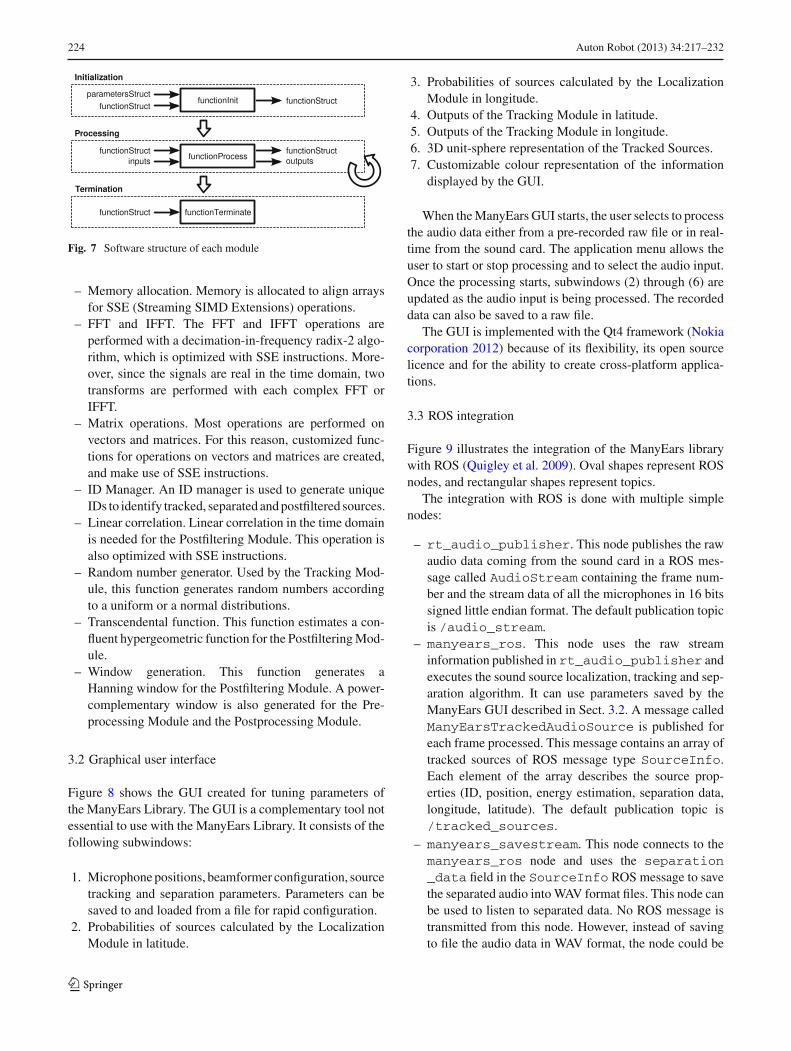
ManyEars’ functions, as shown in the block diagramsof Sect. 2, are managed according to three stages: Ini-tialization, Processing, and Termination. Figure 7 illus-trates these stages. All the parameters are stored in thestructure parametersStruct. This structure is used toprovide parameters to the functionStruct during Ini-tialization. Memory is also allocated for the elements offunctionStruct during this step. This functionStruct is then used to perform many processing oper-ations. During Processing, input arguments are used andoutput arguments are generated. Moreover, the elements offunctionStruct are updated during this step. Finally,Termination is performed and the previously allocated mem-ory is freed.
To avoid dependency on external libraries, the followingutility functions have been created and are used to performvarious computations:
123
224 Auton Robot (2013) 34:217–232
Fig. 7 Software structure of each module
– Memory allocation. Memory is allocated to align arraysfor SSE (Streaming SIMD Extensions) operations.
– FFT and IFFT. The FFT and IFFT operations areperformed with a decimation-in-frequency radix-2 algo-rithm, which is optimized with SSE instructions. More-over, since the signals are real in the time domain, twotransforms are performed with each complex FFT orIFFT.
– Matrix operations. Most operations are performed onvectors and matrices. For this reason, customized func-tions for operations on vectors and matrices are created,and make use of SSE instructions.
– ID Manager. An ID manager is used to generate uniqueIDs to identify tracked, separated and postfiltered sources.
– Linear correlation. Linear correlation in the time domainis needed for the Postfiltering Module. This operation isalso optimized with SSE instructions.
– Random number generator. Used by the Tracking Mod-ule, this function generates random numbers accordingto a uniform or a normal distributions.
– Transcendental function. This function estimates a con-fluent hypergeometric function for the Postfiltering Mod-ule.
– Window generation. This function generates aHanning window for the Postfiltering Module. A power-complementary window is also generated for the Pre-processing Module and the Postprocessing Module.
3.2 Graphical user interface
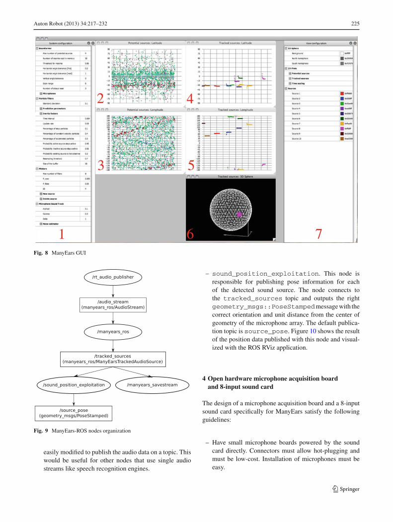
Figure 8 shows the GUI created for tuning parameters ofthe ManyEars Library. The GUI is a complementary tool notessential to use with the ManyEars Library. It consists of thefollowing subwindows:
1. Microphone positions, beamformer configuration, sourcetracking and separation parameters. Parameters can besaved to and loaded from a file for rapid configuration.
2. Probabilities of sources calculated by the LocalizationModule in latitude.
3. Probabilities of sources calculated by the LocalizationModule in longitude.
4. Outputs of the Tracking Module in latitude.5. Outputs of the Tracking Module in longitude.6. 3D unit-sphere representation of the Tracked Sources.7. Customizable colour representation of the information
displayed by the GUI.
When the ManyEars GUI starts, the user selects to processthe audio data either from a pre-recorded raw file or in real-time from the sound card. The application menu allows theuser to start or stop processing and to select the audio input.Once the processing starts, subwindows (2) through (6) areupdated as the audio input is being processed. The recordeddata can also be saved to a raw file.
The GUI is implemented with the Qt4 framework (Nokiacorporation 2012) because of its flexibility, its open sourcelicence and for the ability to create cross-platform applica-tions.
3.3 ROS integration
Figure 9 illustrates the integration of the ManyEars librarywith ROS (Quigley et al. 2009). Oval shapes represent ROSnodes, and rectangular shapes represent topics.
The integration with ROS is done with multiple simplenodes:
– rt_audio_publisher. This node publishes the rawaudio data coming from the sound card in a ROS mes-sage called AudioStream containing the frame num-ber and the stream data of all the microphones in 16 bitssigned little endian format. The default publication topicis /audio_stream.
– manyears_ros. This node uses the raw streaminformation published in rt_audio_publisher andexecutes the sound source localization, tracking and sep-aration algorithm. It can use parameters saved by theManyEars GUI described in Sect. 3.2. A message calledManyEarsTrackedAudioSource is published foreach frame processed. This message contains an array oftracked sources of ROS message type SourceInfo.Each element of the array describes the source prop-erties (ID, position, energy estimation, separation data,longitude, latitude). The default publication topic is/tracked_sources.
– manyears_savestream. This node connects to themanyears_ros node and uses the separation_data field in the SourceInfo ROS message to savethe separated audio into WAV format files. This node canbe used to listen to separated data. No ROS message istransmitted from this node. However, instead of savingto file the audio data in WAV format, the node could be
123
Auton Robot (2013) 34:217–232 225
Fig. 8 ManyEars GUI
Fig. 9 ManyEars-ROS nodes organization
easily modified to publish the audio data on a topic. Thiswould be useful for other nodes that use single audiostreams like speech recognition engines.
– sound_position_exploitation. This node isresponsible for publishing pose information for eachof the detected sound source. The node connects tothe tracked_sources topic and outputs the rightgeometry_msgs::PoseStampedmessage with thecorrect orientation and unit distance from the center ofgeometry of the microphone array. The default publica-tion topic is source_pose. Figure 10 shows the resultof the position data published with this node and visual-ized with the ROS RViz application.
4 Open hardware microphone acquisition boardand 8-input sound card
The design of a microphone acquisition board and a 8-inputsound card specifically for ManyEars satisfy the followingguidelines:
– Have small microphone boards powered by the soundcard directly. Connectors must allow hot-plugging andmust be low-cost. Installation of microphones must beeasy.
123

226 Auton Robot (2013) 34:217–232
Fig. 10 Visualization of sound source position using ROS RViz
Fig. 11 Microphone board
– Minimalist design supporting up to eight microphoneinputs and one stereo output.
– Minimize physical dimensions for installation on amobile robot.
– Low power consumption and support of a wide range ofpower supply voltage.
– Minimum signal resolution of 12 effective bits and sam-pling rates from 8 to 192 kSamples/sec.
– Fabrication cost comparable or lower to commercially-available sound cards.
– Compatible with multiple operating systems (Linux,MacOS, Windows).
– Processing of the ManyEars algorithm is done externally,on the host computer, reducing processing power require-ments on the sound card and facilitating portability andmaintainability.
Figure 11 shows one of the microphone boards designed.Each microphone board has its own preamplifier circuit,
which is powered by the sound card at 4.3 V. The mainelectronic components on the top side of the board includethe omnidirectional microphone (CUI CMA-4544PF-W) andthe preamplifier (STMicroelectronics TS472). The frequencyresponse of the electret microphone is relatively flat from 20Hz to 20 kHz. The back side of the board is composed of theRJ-11 connector (low-cost standard telephone jack style) anda potentiometer for easy preamplifier gain adjustment. Par-allel insertion of the RJ-11 connector prevents the power linefrom making contact with the data line when insertion occurs,making the connection hot pluggable. Signals are mapped tothe RJ-11 connector lines such that a standard telephone cablecan be used. The connector also has a latch mechanism, whichensures reliable physical connections. The preamplifier hasa high signal-to-noise ratio (more than 70 dB according tothe TS472 datasheet), differential input and output channelsand a maximum closed loop gain of approximately 40 dB,required to obtain a peak-to-peak amplitude of 4.3 V at theoutput. This maximizes the dynamic range of the codecs usedby the sound card. Moreover, the microphone preamplifiersare positioned as close as possible to the electret microphonein order to reduce the effects of electromagnetic interferenceand to preserve a good signal-to-noise ratio.
To design the sound card, the first step was to choosethe hardware interface to be used. The USB 2.0 High-Speedinterface is a good choice because it is more commonly avail-able compared to FireWire, and can be used directly to powerthe sound card unlike the standard Ethernet ports. The USB2.0 transfer rate reaches 480 Mbits/sec, which is sufficient totransfer the raw (uncompressed) data of eight microphonesand one stereo output. Recently introduced, the USB AudioClass 2.0 standard (Knapen 2006) includes more channels
123

Auton Robot (2013) 34:217–232 227
Fig. 12 Hardware block diagram
and better sampling resolutions and rates compared to AudioClass 1.0. The total consumption of the system must notexceed 2.5 W (500 mA @ 5V) for normal USB configu-ration. The design is based on the XMOS USB Audio 2.0Multichannel Reference Design (XMOS ltd 2012) to meetthe power and interface requirements. This standard is con-venient as it is automatically supported by standard drivers(ALSA for Linux, CoreAudio for OSX). On Windows plat-forms, a third party driver provided by XMOS partners isused because the USB Audio Class 2.0 is not yet supportednatively. The XMOS is strictly used to operate the codec andforward the sound stream to the host computer (no processingis performed by the sound card).
Figure 12 shows a block diagram of the hardware imple-mentation. The analog signal coming from the microphonesis transmitted in differential mode to the codecs. Differen-tial mode is preferred to single-ended signalling because ofnoise immunity and because it increases the dynamic rangeof the analog/digital converter of the codec. Since the soundcard is designed to operate on a robot, many external devicescan induce electromagnetic interference in the transmittedsignal. Twisted pairs for differential signal transmission dis-tribute the interference and a differential amplifier rejects thecommon mode noise, which minimizes the effect of overallelectromagnetic interference.
The Preamp module uses a differential audio amplifier(National Semiconductor LME49726) that biases the signal
for the codec’s input and also filters the signal to avoidaliasing. This audio amplifier is especially intended for audioand it uses a single power supply. The band-pass filter in thePreamp module has a flat frequency response in the audiofrequency band and has a rejection of 20 dB at the low fre-quencies. The configuration of the anti-aliasing filters is theone suggested by the codec manufacturer. Two four-inputcodec chips (Cirrus Logic CS42448) are used for analog todigital conversion. Data is transfered using the I2S protocolto the XMOS processor. The codecs are configured with theI2C protocol.
The XMOS XS1-L2 dual core microprocessor operatesat 1000 MIPS and is of particular interest for mobile appli-cations. Eight threads for each core are independently acti-vated by events and do not run continuously with the systemclock if not used. This reduces power consumption since onlyactive threads require power. Threads are scheduled directlyby the XMOS chip, making real-time performances possi-ble without any operating system. An external PLL (CirrusLogic CS2300CP) is used to synchronize the codecs and theXMOS cores. This is required to avoid jitter in the clockcontrolling the sampling of the analog inputs. The originalXMOS firmware is used from the reference design, with asmall addition to support the second codec. The firmware isstored in the 512k flash memory connected via SPI.
An XTAG2 connector (JTAG interface) is used for pro-gramming the SPI flash memory and for debugging. There
123

228 Auton Robot (2013) 34:217–232
Fig. 13 Sound card
is also an expansion port available compatible with XMOSstandard SKT connector for future use. The XMOS processoris connected to the USB port using an external USB 2.0 PHY(SMSC USB3318). The PHY requires a 13 MHz clock tooperate.
The sound card also has an external power connector (from7 V to 36 V) if USB power is not available or insufficient. Theswitching power supply (Texas Instruments PTN78000W)uses the wide range input power and converts it effiencientlyto the required 5V. In case power is supplied both throughUSB and an external power supply, the Power Selectionmodule (Texas Instruments TPS2111) prioritizes the externalpower source. Figure 13 presents a picture of the designedsound card.
Table 2 summarizes the characteristics of the designedmicrophone board and sound card. The microphone designfiles are available online (Abran-Côté et al. 2012) underthe Creative Commons Attribution-ShareAlike 3.0 Unportedlicense (Creative Commons 2012). For the sound card, allthe design files, gerbers and firmware are available online(Abran-Côté et al. 2012) under the Creative CommonsAttribution-ShareAlike 3.0 Unported license (Creative Com-mons 2012).
5 Demonstration test cases
The ManyEars Library comes with many demonstration testcases available online (Grondin et al. 2012), with parameterstuned to optimize performance. Two of these test cases arepresented here: one with static sound sources, and anotherwith moving sound sources. Figure 14 illustrates the coordi-nate system used in these test cases. The results in this sectionare displayed with a Matlab/Octave script (demo.m).
5.1 Static sound sources
This test case uses an 8-microphone cubic array. Accord-ing to Rabinkin (1998), the performance of a beamformerwith speech sources (with a bandwidth between 100 Hz and
Table 2 Microphone board and sound card characteristics
Item DimensionsLength (mm) Width (mm) Height (mm)
Microphone 23 23 15
Sound card 125 74 15
Power source Power supply
Voltage (V) Current (A) Power (W)
External power 7 0.332 2.324
(without 12 0.192 2.376
microphones) 24 0.114 2.736
36 0.0884 3.182
External (with 7 0.343 2.401
microphones) 12 0.208 2.496
24 0.118 2.843
36 0.0884 3.182
USB (without 5 0.434 2.168
microphones)
USB (with 5 0.449 2.246
microphones)
Maximum with external power 3.182
Maximum with USB power 2.246
Additional information
Max. sampling latency between channels 16 us
Mean noise floor −132 dBV
Maximum noise floor −112 dBV
Fig. 14 Coordinate system
4 kHz) is optimized when the spacing between the micro-phones varies between 20 cm and 1 m. A 0.32 m × 0.32 m ×0.32 m array is used to make the spatial gain uniform and to fiton top of a mobile robot (e.g., Pioneer 2 platforms). The diam-eter of each microphone is 0.8 cm. For the results presented
123

Auton Robot (2013) 34:217–232 229
Fig. 15 Positions of the tracked sources
in this paper, the array is positioned at 0.6 m above the floor,in a room of 10 m × 10 m × 2.5 m with normal reverberationand some audible background noise generated by fans andother electronics. Two loud speakers with a diameter of 6 cmare used as sound sources, at a distance of 1.5 m and sep-arated by 90◦. Each speaker is placed approximately 0.6 mabove the floor. Speech segments of two female speakers areplayed during 10 seconds. The signals of the microphonesare recorded and then processed with the ManyEars Library.
Figure 15 represents the longitude and the latitude of thetracked sound sources. These positions match the locationsof the loud speakers, with the small difference in latitudecaused by the offset between the heights of the speakers. Thelocalization error of ManyEars has been characterized to beless than 1◦ (Valin et al. 2006a). Figures 16 and 17 show thespectrograms of source 1 and source 2, respectively. Sepa-rated and postfiltered spectrograms match many features inthe clean spectrograms. Speech intelligibility and recogni-tion are evaluated in (Yamamoto et al. 2006, 2007, 2005,2006, 2005).
5.2 Moving sound sources
To demonstrate the use of ManyEars on a mobile robot andwith an asymmetric array, this test case uses the microphonesarray on IRL-1, as shown by Fig. 18. Two scenarios havebeen evaluated, illustrated by Fig. 19, with human speakersproducing uninterrupted speech sequences:
– Scenario A: The two sources are separated by 90◦ withrespect to the xy-plane. They move by 90◦ and then comeback to their initial position.
Fig. 16 Spectrograms for source 1
Fig. 17 Spectrograms for source 2
– Scenario B: The two sources are separated by 180◦ withrespect to the xy-plane. They move to the position of theother speaker and cross each other.
123

230 Auton Robot (2013) 34:217–232
Fig. 18 IRL-1 with the microphones identified by the red circles
(a) (b)
Fig. 19 Positions of the moving sources
Fig. 20 Positions of the tracked sources
As shown by Fig. 20(a), the tracked sources match thepositions of the moving sources. In scenario B, the inertiaof the particles used for tracking solve the source crossingproblem. However, sources could have swapped if bothspeakers would have come close to each other at the same
time, and then move back to their initial position. This prob-lem can be solved by reducing the inertia of the particles(with parameters αl
s( f ) and βls( f ) introduced in Sect. 2.3),
but then sources swapping could occur when speakers cross.Parameters of the Tracking module were tuned to find a trade-off between these two scenarios.
6 Conclusion
Compared to vision, there is not much hardware and softwaretools to implement and experiment with robot audition. TheManyEars Open Framework offers both software and hard-ware solutions to do so. The proposed system is versatile,portable and low-cost. The ManyEars C library is compat-ible with ROS and provides an easy-to-use GUI for tuningparameters and visualizing the results in real-time. Softwareand hardware components can be easily modified for effi-cient integration of new audio capabilities to robotic plat-forms. This new version of ManyEars has recently been usedto demonstrate a speaker identification algorithm (Grondinand Michaud 2012), and is currently used in augmented tele-operation and human-robot interaction scenarios with IRL-1, a humanoid robot with compliant actuators for motionand manipulation, artificial vision and audition, and facialexpressions (Ferland et al. 2012). Integration of ManyEarsand HARK libraries in ROS suggests that there is a potentialfor further standardization of ROS audio components, whichcould include data structures, standard DSP operations, audiocodecs, and Matlab / Octave script integration. In addition,since the introduction of ManyEars, new methods have beenproposed to detect the exact number of active sources (Danesand Bonnal 2010; Ishi et al. 2009), for tracking moving peo-ple (Yao and Odobez 2008), and for sound source separationusing Independent Component Analysis (Mori et al. 2006),and these could be easily added to the ManyEars open frame-work. This effort would lead to a collection of useful, opensource and portable tools similar to OpenCV (OpenCV 2012)for image processing.
Acknowledgments This work was supported in part by the NaturalSciences and Engineering Research Council of Canada, the CanadianFoundation for Innovation and the Canada Research Chair program.
References
Abran-Côté, D., Bandou, M., Béland, A., Cayer, G., Choquette, S.,Gosselin, F., Robitaille, F., Telly Kizito, D., Grondin, F., Létourneau,D. (2012). Eight Sound USB. Retrieved January 22, 2013 from http://eightsoundsusb.sourceforge.net.
Bonnal, J., Argentieri, S., Danes, P., & Manhes, J. (2009). Speakerlocalization and speech extraction with the EAR sensor. In Proceed-ings of the IEEE International Conference on Intelligent Robots andSystems (pp. 670–675).
123

Auton Robot (2013) 34:217–232 231
Cohen, I., & Berdugo, B. (2002). Noise Estimation by Minima Con-trolled Recursive Averaging for Robust Speech Enhancement. SignalProcessing Letters, 9(1), 12–15.
Creative Commons (2012). Attribution-ShareAlike 3.0 Unported.Retrieved January 22, 2013 fromhttp://http://creativecommons.org/licenses/by-sa/3.0/legalcode.
Danes, P., & Bonnal, J. (2010). Information-theoretic detection ofbroadband sources in a coherent beamspace MUSIC scheme. In Pro-ceedings of the IEEE International Conference on Intelligent Robotsand Systems (pp. 1976–1981).
Ephraim, Y., & Malah, D. (1984). Speech Enhancement Using a Min-imum Mean-Square Error Short-Time Spectral Amplitude Estima-tor. IEEE Transactions on Acoustics, Speech and Signal Processing,32(6), 1109–1121.
Ephraim, Y., & Malah, D. (1985). Speech Enhancement Using a Mini-mum Mean-Square Error Log-Spectral Amplitude Estimator. IEEETransactions on Acoustics, Speech and Signal Processing, 33(2),443–445.
Ferland, F., Létourneau, D., Frémy, J., Legault, M. A., Lauria, M., &Michaud, F. (2012). Natural interaction design of a humanoid robot.Journal of Human-Robot Interaction (in press).
Free Software Foundation, Inc. (2012). GNU General Public License.Retrieved January 22, 2013 from http://www.gnu.org/licenses/gpl.html.
Grondin, F., & Michaud, F. (2012). WISS, a speaker identification sys-tem for mobile robots. In Proceedings of the IEEE InternationalConference on Robotics and Automation (pp. 1817–1822).
Grondin, F., Valin, J.M., Létourneau, D. (2012). The ManyEars Project:Microphone Array-Based Audition for Mobile Robots. RetrievedJanuary 22, 2013 from http://manyears.sourceforge.net/.
Haykin, S. (2002). Adaptive Filter Theory. New York: Prentice Hall.IntRoLab (2012). ManyEars ROS Package. Retrieved January 22, 2013
from http://introlab.github.com/introlab-ros-pkg/.Ishi, C., Chatot, O., Ishiguro, H., & Hagita, N. (2009). Evaluation
of a MUSIC-based real-time sound localization of multiple soundsources in real noisy environments. In Proceedings of the IEEE Inter-national Conference on Intelligent Robots and Systems (pp. 2027–2032).
Knapen, G. (2006). Universal Serial Bus Device Class Definition forAudio Devices. Retrieved January 22, 2013 from http://www.usb.org/developers/devclass_docs/Audio2.0_final.zip.
Létourneau, D., Valin, J. M., Côté, C., & Michaud, F. (2005). FlowDesigner: the Free Data-flow Oriented Development Environment.Software, 2, 3.
Michaud, F., Côté, C., Létourneau, D., Brosseau, Y., Valin, J. M.,Beaudry, E., et al. (2007). Spartacus Attending the 2005 AAAI Con-ference. Autonomous Robots, 22(4), 369–383.
Mori, Y., Takatani, T., Saruwatari, H., Hiekata, T., & Morita, T. (2006).Blind source separation combining SIMO-ICA and SIMO-Model-Based binary masking. In Proceedings of the IEEE InternationalConference on Acoustics, Speech and Signal Processing (pp. 81–84).
Nakadai, K., Ince, G., Nakamura, K., & Nakajima, H. (2012). Robotaudition for dynamic environments. In Proceedings of the IEEEInternational Conference on Signal Processing, Communication andComputing (pp. 125–130).
Nakadai, K., Takahashi, T., Okuno, H., Nakajima, H., Hasegawa,Y., & Tsujino, H. (2010). Design and Implementation of RobotAudition System ‘HARK’ Open Source Software for Listen-ing to Three Simultaneous Speakers. Advanced Robotics, 5(6),739–761.
Nakamura, K., Nakadai, K., & Ince, G. (2012). Real-time super-resolution sound source localization for robots. In Proceedings ofthe IEEE International Conference on Intelligent Robots and Sys-tems (pp. 694–699).
Nokia corporation (2012). Qt - A Cross-platform Application and UIFramework. Retrieved January 22, 2013 from http://qt-project.org/.
OpenCV (2012). OpenCVWiki. Retrieved January 22, 2013 from http://opencv.willowgarage.com/wiki/.
Otsuka, T., Nakadai, K., Ogata, T., & Okuno, H. G. (2011). Bayesianextension of MUSIC for sound source localization and tracking. InProceedings of the IEEE International Conference on Spoken Lan-guage Processing (pp. 3109–3112).
Parra, L., & Alvino, C. (2002). Geometric Source Separation: MergingConvolutive Source Separation with Geometric Beamforming. IEEETransactions on Speech and Audio Processing, 10(6), 352–362.
Quigley, M., Gerkey, B., Conley, K., Faust, J., Foote, T., Leibs, J.,et al. (2009). ROS: an Open-source Robot Operating System. InOpen-Source Software Workshop of the IEEE International Con-ference on Robotics and Automation.
Rabinkin, D. (1998). Optimum sensor placement for microphone arrays.Ph.D. thesis, State University of New Jersey, New Brunswick.
Valin, J.M., Létourneau, D. (2008). Flow Designer http://flowdesigner.sourceforge.net/.
Valin, J. M., Michaud, F., & Rouat, J. (2006a). Robust 3D localiza-tion and tracking of sound sources using beamforming and particlefiltering. In Proceedings of the IEEE International Conference onAcoustics. Speech and Signal Processing, 4, 841–844.
Valin, J. M., Michaud, F., & Rouat, J. (2006b). Robust localization andtracking of simultaneous moving sound sources using beamformingand particle filtering. Robotics and Autonomous Systems, 55(3), 216–228.
Valin, J.M., Michaud, F., Rouat, J., Létourneau, D. (2003). Robust boundsource localization using a microphone array on a mobile robot. InProceedings of the IEEE International Conference on IntelligentRobots and Systems (vol. 2, pp. 1228–1233).
Valin, J.M., Rouat, J., Michaud, F. (2004). Enhanced robot auditionbased on microphone array source separation with post-filter. In Pro-ceedings of the IEEE International Conference on Intelligent Robotsand Systems(vol. 3, pp. 2123–2128).
Valin, J. M., Yamamoto, S., Rouat, J., Michaud, F., Nakadai, K., &Okuno, H. (2007). Robust Recognition of Simultaneous Speech bya Mobile Robot. IEEE Transactions on Robotics, 23(4), 742–752.
Wolff, R., Lasseck, M., Hild, M., Vilarroya, O., & Hadzibeganovic, T.(2009). Towards human-like production and binaural localization ofspeech sounds in humanoid robots. In Proceedings of the IEEE Inter-national Conference on Bioinformatics and Biomedical Engineering(pp. 1–4).
XMOS ltd: USB Audio 2.0 Multichannel Reference Design (2012).Retrieved January 22, 2013 from http://www.xmos.com/products/development-kits/usbaudio2mc.
Yamamoto, S., Nakadai, K., Nakano, M., Tsujino, H., Valin, J. M.,Komatani, K., et al. (2006). Real-time robot audition system thatrecognizes simultaneous speech in the real world. In Proceedings ofthe IEEE International Conference on Intelligent Robots and Systems(pp. 5333–5338).
Yamamoto, S., Nakadai, K., Nakano, M., Tsujino, H., Valin, J. M.,Komatani, K., et al. (2007). Design and implementation of a robotaudition system for automatic speech recognition of simultaneousspeech. In Proceedings of the IEEE Workshop on Automatic SpeechRecognition & Understanding (pp. 111–116).
Yamamoto, S., Nakadai, K., Valin, J. M., Rouat, J., Michaud, F.,Komatani, K., et al. (2005). Making a robot recognize three simul-taneous sentences in real-time. In Proceedings of the IEEE Inter-national Conference on Intelligent Robots and Systems (pp. 4040–4045).
Yamamoto, S., Takeda, R., Nakadai, K., Nakano, M., Tsujino, H., et al.(2006). Recognition of simultaneous speech by estimating reliabilityof separated signals for robot audition. In Yang, Q. & Webb, G.(Eds.), Proceedings of the 9th Biennial Pacific Rim International
123

232 Auton Robot (2013) 34:217–232
Conference on Artificial Intelligence (PRICAI) (Vol. 4099, pp. 484–494). Heidelberg: Springer.
Yamamoto, S., Valin, J. M., Nakadai, K., Rouat, J., Michaud, F., Ogata,T., et al. (2005). Enhanced robot speech recognition based on micro-phone array aource separation and missing feature theory. In Pro-ceedings of the IEEE International Conference on Robotics andAutomation. (pp. 1477–1482).
Yao, J., & Odobez, J. M. (2008). Multi-camera multi-person 3D spacetracking with MCMC in surveillance scenarios. In Proceedings of theWorkshop on Multi-camera and Multi-modal Sensor Fusion Algo-rithms and Applications.
Author Biographies
François Grondin received hisBachelor’s degree (’09) in Elec-trical Engineering from McGillUniversity, Québec, Canada, andhis Master’s degree (’11) in Elec-trical Engineering from the Uni-versité de Sherbrooke, Québec,Canada. He is currently workingtoward the Ph.D. degree in Elec-trical Engineering at the Univer-sité de Sherbrooke. His researchinterests are on robot auditionand speaker identification.
Dominic Létourneau receivedhis Bachelor’s degree (’99) inComputer Engineering and hisMaster’s degree (’01) in Electri-cal Engineering from the Uni-versité de Sherbrooke, Québec,Canada. Since 2001, he is aresearch engineer at the IntRo-Lab. His research interests covercombination of systems andintelligent capabilities to increasethe usability of autonomousmobile robots in the real world.His expertise lies in artificialvision, mobile robotics, robot
programming and integrated design. He is a member of OIQ (Ordredes ingénieurs du Québec).
François Ferland received hisBachelor’s degree (’08) in Com-puter Engineering and his Mas-ter’s degree (’10) in ElectricalEngineering from the Universitéde Sherbrooke, Québec, Canada.He is currently working towardthe Ph.D. degree in ElectricalEngineering at the same univer-sity. His research interests areon human-robot interaction andselective attention mechanismsfor cognitive robotics.
Vincent Rousseau received hisBachelor’s degree (’08) in Com-puter Engineering from ESEO,France, and his Master’s degree(’12) in Electrical Engineeringfrom the Université de Sher-brooke, Québec, Canada. Hisresearch interests are on soft-ware integration for human-robot interaction.
François Michaud received hisBachelor’s degree (’92), Mas-ter’s degree (’93) and Ph.D.degree (’96) in Electrical Engi-neering from the Université deSherbrooke, Québec, Canada.After completing postdoctoralwork at Brandeis University,Waltham MA (’97), he becamea faculty member in the Depart-ment of Electrical Engineeringand Computer Engineering ofthe Université de Sherbrooke,and founded IntRoLab (formerlyLABORIUS), a research lab-oratory working on designing
intelligent autonomous systems that can assist humans in living environ-ments. His research interests are in architectural methodologies for intel-ligent decision-making, design of autonomous mobile robots, socialrobotics, robots for children with autism, robot learning and intelligentsystems. Prof. Michaud held a Canada Research Chair (2001–11) inMobile Robots and Autonomous Intelligent Systems, and is the Direc-tor of the Interdisciplinary Institute for Technological Innovation (3IT).He is a member of IEEE, AAAI and OIQ (Ordre des ingénieurs duQuébec). In 2003, he received the Young Engineer Achievement Awardfrom the Canadian Council of Professional Engineers.
123