the longitudinal bending behaviour of composite box girder bridges having incomplete interaction
TRANSCRIPT

The longitudinal bending behaviourof composite box girder bridgeshaving incomplete interaction
K. R. Moffatt, BE, PhD, DIC, CEng, MIStructE, MIE(Aust)
Research Fellow, Department of Civil Engineering, Imperial College of Science and Technology, London
P. J. DowMng, BE, PhD, DICCEng, MIStructE, MICE, MRINA
Reader in Steel Structures, Department of Civil Engineering, Imperial College of Science and Technology, London
SynopsisDetails are given of a numerical study of the elastic longitudinalbending behaviour of composite box girder bridges in which theuse of flexible shear connectors results in incomplete interac-tion between the slab and girder components. The results of thestudy provided background for the formulation of design rulesincluded in the draft Unified Bridge Code, and the rules arediscussed in the light of these results.
Notation
B = half the distance between web centre lines or the
distance between a web centre line and the free edge ofa flange
fx, f,, = moduli of elasticity in tension and compression for anorthotropic material in the x and y directions, respec-tively
f = force in a shear connector
F = total longitudinal shearing force in a transverse row ofshear connectors
G = modulus of elasticity in shearK
rs = total slip modulus of a row of shear connectorsK$ = slip modulus of a shear connectork -slip modulus of a shear connection per unit length of a
composite girder per breadth of flange BL = span of a girderw = displacement in the z directionxry,z= rectangular cartesian co-ordinates (right-handed sys-
tem of co-ordinates)
a = ratio of the slip modulus of the shear connectors placeddirectly over the webs to the total slip modulus of theconnectors of a girder
y = non-dimensional factor/7C„/FCACSVxy = Poisson
's ratio for induced strain in the x direction due
to a strain in the y direction for an orthotropic materialff = extensional stress*V - effective breadth ratio in respect of extensional stresses
Superscriptsc = reference to concrete slab
= reference to steel reinforcement
,-Concrete slab a-bn
r
s reference to steel plate
Subscriptsc - complete interaction condition/ = incomplete interaction condition
Introduction
In a box girder bridge of the type shown in Fig 1, natural bondbetween the concrete slab and the steel plate Is unlikely toprovide composite action throughout the life of the bridge. Once
[>==?=?=
Shear conrwetors
-L
Steel box
girder
Fig J. Cross-section of typical composite box girder bridge
the bond Is broken, the composite action is almost entirelyprovided by the mechanical shear connectors, and forcesdevelop in them as a result of both overall deformation of thebridge and local deformation of the top flange.
Since the shear connectors are of finite stiffness, these forces
will cause some relative movement between the concrete slab
and the steel plate. Clarke and Morley demonstrated that thismovement can have a considerable effect on the local
behaviour of a flange1. However, there was a lack of informationon the effect of the movement on the overall behaviour of a
bridge and, therefore, the work described in this paper wasundertaken.
The finite element method of analysis was used to obtain theresults presented. Buckling and inelastic behaviour were notconsidered.
Details of girders used in studyThe girders used in the study were considered to be simplysupported and to have the cross-sections shown in Fig 2, decksof breadth to length ratio (fl/Z.) of 0 05 or 0-20, and enddiaphragms only. In the analyses of these girders, it wasassumed that the webs behaved in accordance with the
elementary theory of bending and that the diaphragms hadinfinite in-plane rigidity but no out-of-plane rigidity; in-vestigations have shown that, for girders of practical dimen-sions, these assumptions lead to no significant error in respectof longitudinal bending behaviour2
Details of the various connections introduced into the top
flange of the girders are given in Table 1. The connection II wasconsidered to have values of slip modulus k (defined as the slipmodulus of the shear connection per unit length of girder per
breadth of flange B) and distribution coefficient a (defined asthe ratio of the slip modulus of the connectors placed directlyover the webs to the total slip modulus of the connection) such
The Structural Engineer/September 1978/No. 3/Voluine 56B 53

-3660 -
25og5o
Area =i5O00 mm21
3660 .
Tofal steel
T-
area = 10000 mm2
"
i
25 1
Area = i5000mm2
2
3660
i
1CO
1212
3
1830 - 3660- -3660 3660 -1830
12 12
T
F/j? 2. Cross-sections of girders used in study
i
4
12 12
T
All dimensions in mm
TABLE 1-Details of shear connections between concrete
slab and steel plate of girders having cross-sections shown inFig 2
Shear connection/ N/mm '
mm /
11
12
13
14
15
C
3 88 x 103
3 88 x 1033 88 x 103
3 88 X 103
5 82 x 1031 00 x lO'2
1
I
1 2
12
T2
that the likely effects of slip and separation on the longitudinalbending behaviour of the girders would be negligible**. Theconnections 12 to 14 were considered to have the same slipmodulus as the connection II, but different distribution
coefficients. The connection 15 was arbitrarily assumed to have
a 50% greater slip modulus than the connections II to 14 andthe same distribution coefficient as the connection 14. The
connection C was assigned a slip modulus and distributioncoefficient which, for all practical purposes, ensured completeinteraction between the concrete slab and steel plate.
These composite girders are representative of those occur-ring in practice, although some simplifications were introducedfor the purpose of the study.
Preliminary investigationsSome preliminary investigations were carried out to determinesuitable finite element meshes for use in analysing the girdersand to establish the similarities in the longitudinal bendingbehaviour of girders having different cross-sectional properties.For the purpose of the investigations, the girders with the shearconnections 14 and C were analysed for a uniform load over thelength of each web and for a point load over each web at themid-span. In the presentation of the results of these analyses,the values obtained for the girders with the connection C havebeen used as a basis for non-dimensionalising those obtainedfor the girders with the connection 14.
Finite element idealisations
In obtaining the various finite element solutions the followingidealisation schemes were employed:
(a) For the tee girders, the slab, the reinforcement(considered as an equivalent plate) and the flange plate
were represented by eccentric shell elements (typeR56), the web plate by eccentric beam elements (typeB4), and the shear connectors by concentric linkage
elements (type L23) that allowed slip in the plane ofthe concrete-steel interfacej.
(b) For the box girders, the slab and the top flange platewere represented by eccentric shell elements (typeR6), the web and bottom flange plates by concentricshell elements (type R33), and the shear connectors byconcentric linkage elements (type L33) that allowedslip in the plane of the concrete-steel interface.
For the mesh investigation, the girders having the cross-sections 1, 3 and 4 were each analysed using several differentmesh schemes for the flanges. (Because of the assumptionmade regarding the behaviour of the webs (see previoussection), it was not necessary to consider different meshschemes for the box girder webs; the results would beindependent of the number of mesh divisions used over thedepth of the webs.) It was found that for each girder asubdivision of the flange (or equivalent subdivisions in the caseof the girders of cross-section 4) as shown in Fig 3 gave valuesof the maximum deflection, plate longitudinal stress, slablongitudinal stress and shear connector longitudinal force thatwere within 5% of those obtained using finer mesh schemes.
Accordingly, all subsequent results given in this Paper were
* The shear connection was in fact designed, in accordance with theworking load criteria of CP117: Part 2: 196 73
, to accommodate the
longitudinal interface shear forces developed by the maximum pointload which could be placed at the mid-span of the tee girder with cross-section 1 and B/L ratio of 0 05. It was assumed that this connection(and the other connections considered in the Paper) would be providedby 19mm by 100mm headed studs. On the basis of information given inReference 4
, the slip modulus for these studs was taken as 0 40 x108N/mm.
t In the finite element idealisations (see following section) the shearconnections were represented by discrete connectors (linkage ele-ments) evenly spaced across the girder flanges. The stiffnesses of theseconnectors were adjusted to give values for the slip modulus k anddistribution coefficient a appropriate to any particular connection.
t In all the analyses, it was assumed that uplift forces, which arediscussed in Reference 6, would be resisted by the shear connectorswithout separation, and would not affect the behaviour of the girders.
54 The Structural Engineer/September 1978/No. 3/Volume 56B

t-
hII
Linkage element ateach set o( nodes
8 ® 5x = iOx -
I x
3x l2x xl.U-
NOTE The value of x was varied to give the required B/L ratio for any particular analysis
Fig 3. Subdivision of composite girder flange into elements
obtained using mesh schemes of equivalent grade to thatshown in Fig 3.
assumed that a crack system would develop across theconcrete slabs such that the modulus of elasticity of the
concrete in the longitudinal direction of the girders would bereduced to zero. It was also assumed that some shear transfer
would occur across the cracks (as a result of such phenomena
as aggregate interlock) and this action was accounted for byconsidering finite values* for the modulus of elasticity in shear.
Some of the results obtained from the various analyses are
given in Table 3. It is apparent that the Introduction of theflexible shear connection has similar effects on both the (non-
dimensionalised) deflections and stressesf and almost identicaleffects on the (non-dimensionalised) shear connector forces,
notwithstanding the variations in the concrete properties. Therelative independence of the (non-dimenslonalised) connectorforces on the concrete properties Is further illustrated by thetypical plots shown in Fig 4.
Types of girder cross-sectionSome of the results obtained from the analyses referred to inthe previous sub-section are given In Table 2. These resultsillustrate the markedly similar effects the Introduction of aflexible shear connection have on the longitudinal bendingbehaviour of the various types of composite girder. Because ofthis similarity, and because the idealisation of a tee girderrequires fewer nodes than that of a box girder, the examplesgiven in the remainder of this Paper were based on the teegirders only.
Cracking of concrete slabTo gain some appreciation of the way in which the Incompleteinteraction behaviour of a continuous composite box girderbridge would be affected by cracking of the concrete slab,various analyses were carried out on girders of cross-section 2with the loads applied vertically upwards (to produce longi-tudinal tensile forces in the concrete slab).
In these analyses, the concrete was separately considered tohave and not to have tensile strength. In the latter case. It was
Influence of shear connector flexibility and distributionon girder behaviourFollowing on from the findings of the preliminary investigations,
girders of cross-section 1 were used in a comprehensiveparametric study to investigate the influence of shear connectorflexibility and distribution on the elastic longitudinal bendingbehaviour of composite box girder bridges. The girders wereconsidered to have the various shear connections referred to in
Table 1 and were each analysed for a uniform load over thelength of the web and for a point load over the web at the mid-span. Some of the results obtained from these analyses arepresented in this section. In general, the results obtained for the
. There do not appear to be any definite values given in the literaturefor the modulus of elasticity in shear of cracked concrete. Therefore, twovalues were used in the analyses with a view to ascertaining thesensitivity of the girder behaviour to this parameter.
fThe effects on the deflections and stresses are, of course, morepronounced in those girders with an uncracked concrete slab because ofthe greater contribution of the slab to the girder strength.
TABLE 2-Effect of shear connector flexibility on maximum deflections and maximum longitudinal slab stresses, plate stresses, andconnector forces of various girders (cross-sections 1, 3, and 4, shear connection 14]
Type of loadB
L
w 4/wc
Section Section Section Section Section Section Section Section Section Section Section Section134134134134
Uniform load over 0 05 1 01 1 01 1 01 0 98 0 98 0 98 1 04 1 04 1 04 0 25 0 25 0 24
length of each web 0 20 110 1 10 1 09 0 87 0 87 0-88 1 26 1 25 1 24 0 23 0 24 0 23Point load over each 0 05 1 01 1 01 101 0 93 0-93 0 93 1 13 M3 M3 0-25 0 25 0 25
web at mid-span 0 20 Ml 1 10 1 09 0 79 0 80 0-81 1-40 1 38 1 36 0 25 0 25 0 24
TABLE 3-Effect of shear connector flexibility on maximum deflections and maximum longitudinal reinforcement stresses, plate
stresses, and connector forces of tee girdles {cross-section 2, shear connection 14) having uncracked and cracked slabs
Type of loadB
L (a)
W,4lwc
(b) (c) (a) (b) (c) (a) (b) (c)
fulFc
(a) (b) (c)
Uniform load over 0 05 1 01 1 01 101 0 97 0 98 0-98 1 05 1 03 1 03 0-25 0 28 0 27lengthofweb 0 20 1 15 1 07 1 07 0 84 0 89 0-89 1 32 1 15 1 15 0 26 0 27 0 27
Point load over web 0 05 1 01 1 01 1 01 0-90 0 94 0-94 1 19 1 10 1 10 0 25 0 28 0-27at mid-span 0 20 1 15 1 08 1 08 0 74 0 82 0 82 1 47 1 24 1 24 0 25 0 28 0 26
NOTE: The material properties of the concrete slab used in obtaining the results given in the columns were as follows:Column (a)f), = 23 0 x 103N/mm2 f= 23 0 x 103N/mm2 G = 10 0 x 103N/mm2 i'
J(=0-15
Column (b)£x = 0 f
,, = 23 0 x 103N/mm2 6: '
~
Column (cl£, = 0 = 2 3 0 x 103N/mm
2
: 10 0 x 103N/mm25 0 x 103N/mm2
= 0 15
= 0 15
The Structural Engineer/September 1978/No. 3/Vo(ume 56B 55

0 u
0 3
ii 02
2
0 1
0centre
of flange Position across flange
(a) B/L = 0 05
edgeof flange
a 4
0 3
fi 02
01
centre
of flange Position across flange
lb) B/L = 0-20
edgeof flange
Further, for the point load cases, shear lag action wouldparticularly reduce the effectiveness of the shear connectorsdistributed over the flange in the vicinity of the load, and thislocal effect would influence the mid-span stresses more thanthe deflections.
Effective breadth ratios
The values of the effective breadth ratios in respect of
extensional stresses for the concrete slab and the steel plate at
the mid-span of the various girders are given in Tables 7 and 8.The effective breadth ratios for the girders with the shearconnections C and II are almost identical to those given inReferences 7 and 8 for equivalent steel box girders. For thegirders with the flexible connections (II to 15), as the proportionof the total slip modulus of the shear connectors placed directlyover the web is decreased, the effective breadth ratios for the
concrete slab increase whereas those for the steel platedecrease. These trends are related to the amount of horizontal
shear being transmitted from the steel plate to the concrete slabthrough the connectors distributed over the flange.
Shear connector forces
The values of the longitudinal forces in the shear connectorsplaced directly over the web at the quarter-span and supportsections of the various girders are given in Table 9. It wouldappear from these values that the proportion of the longitudinalshear force taken by the connectors over the web is primarily
Curve 1 : Uncrocked concrete slob ( E„ n 23 0 "101 N/mm2 E,= 23 0« 10'N/mn)!0 lOOxtO'N/mm2 \«,,=0151
Curve2 Cracked concrete slob (Ek = 0 Er=23 0»<I03N/mm; G=50«103N/(rni2
V = 015 I
NOTE : The vertical grid lines are shown at the position of the connectors
Fig 4. Variation of longitudinal shear connector forces atsupport section with position across flange of uniformly loaded
tee girders {cross-section 2) having shear connection 14 andhaving uncracked and cracked concrete slabs
girders with incomplete interaction (shear connections II to 15)are given as a ratio of the corresponding results obtained for thegirders with complete interaction (shear connection C).
TABLE 4-Effect of shear connector flexibility and distribution
on deflections at centre of tee girders (cross-section 1)
Type of loadB
L
wjwc for shear connection:
II 12 13 14
Uniform load over 0 05 100 1 00
length of web 0-20 1 02 1 03Point load over web 0 05 1 00 100
at mid-span 0-20 102 103
15
101 101 1 01
105 1 10 108
101 101 101105 1 11 109
Deflections
The values of the deflections at the centre of the various girdersare given in Table 4. For those girders in which the shearconnectors are placed directly over the web, the deflections arenot significantly affected by the connector flexibility. However,as the proportion of the total slip modulus of the connectorsplaced over the web is decreased, the deflections of the shortergirders (fi/Z. = 0-20) do change noticeably, whereas those ofthe longer girders (S/i = 0 05) do not. This is because lessshear is transmitted across the steel plate of the shorter girders,as a result of shear lag, and hence less force can be transmittedto the concrete slab through the connectors distributed over theflange. As might be expected, the corresponding deflections ofthe girders with the shear connections 14 and 15 are notmarkedly different.
Stresses
The values of the maximum longitudinal extensional stresses inthe concrete slab and the steel plate at the mid-span of thevarious girders are given in Tables 5 and 6. The variations withthe shear connection of these stresses show similar trends to
those of the centre deflections (Table 4). However, the trends
are more marked in the case of the stresses. This is because the
loss of interaction between the concrete slab and the steel plateaffects the upper section modulus of a cross-section to agreater extent than the moment of inertia of the cross-section.
TABLE 5-Effect of shear connector flexibility and distribution
on longitudinal stresses in mid-plane of concrete slab at centreof tee girders (cross-section 1 ]
Type of loadB
L
Ojloc for shear connection:
II 12 13 14 15
Uniform load over
length of web
Point load over web
at mid-span
0 05 1 00 0 99 0 99 0 98 0 980 20 0 96 0 95 0 93 0 87 0 89
0 05 0 98 0 97 0 96 0 93 0 940 20 0 92 0 90 0 86 0 79 0 82
TABLE 6-Effect of shear connector flexibility and distributionon longitudinal stresses in mid-plane of steel plate at centre
of tee girders (cross-section 1)
Type of loadB
L
oj/oc for shear connection:
11 12 13 14 15
Uniform load over
length of web
Point load over web
at mid-span
005
0 20
005
0-20
1 01
107
1 07
1-14
1 02
1 08
108
M6
1 03
M3
MO
1 23
1 04
1 26
1-13
1-40
103
1 22
Ml
1 35
56 The Structural Engineer/September 1978/No. 3/Volume 56B
dependent on the proportion of the total slip modulus of theconnectors placed over the web, and is relatively independentof the BlL ratio of the girder, the total slip modulus of theconnectors, the position along the girder, and the type of load.Further, analyses of girders identical to those with the shear
connection 14 but having a 100mm thick concrete slab gavepractically the same results as those presented in Table 9. It
should also be recalled that the tests described in the previoussection showed that practical variations in the spacing of theconnectors distributed over the flange of a girder only slightlyaffect the proportion of the longitudinal shear force carried bythe connectors directly over the web.
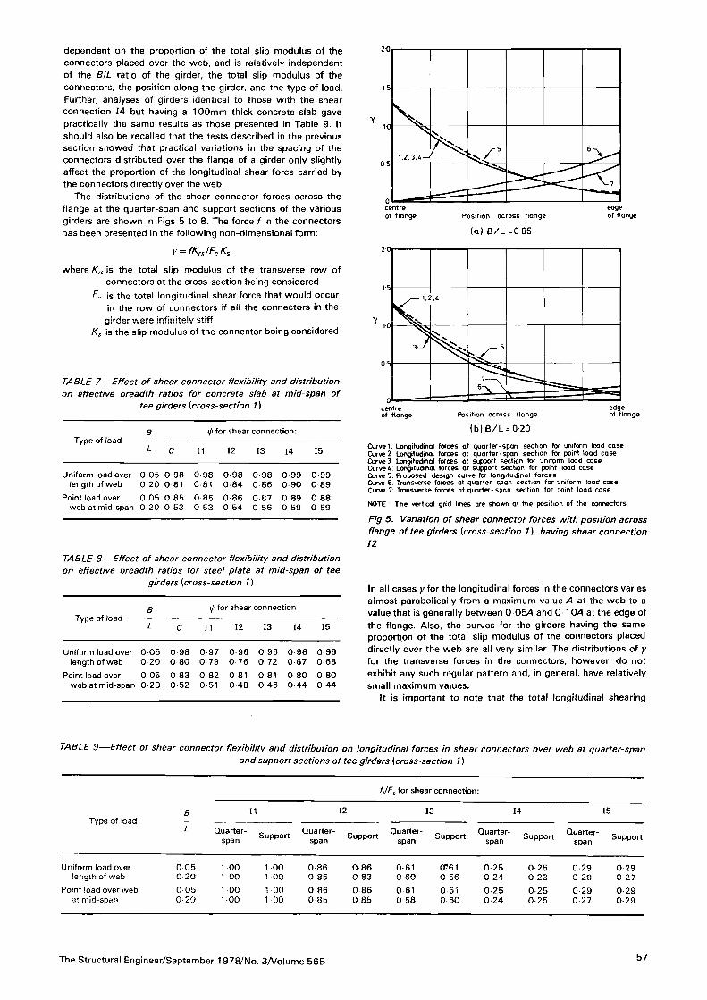
The distributions of the shear connector forces across the
flange at the quarter-span and support sections of the variousgirders are shown in Figs 5 to 8. The force f in the connectorshas been presented in the following non-dimensional form:
v- fKrs/Fc Ks
where Krs is the total slip modulus of the transverse row ofconnectors at the cross-section being considered
Fc is the total longitudinal shear force that would occur
in the row of connectors if all the connectors in the
girder were infinitely stiffK
s is the slip modulus of the connector being considered
TABLE 7-Effect of shear connector flexibility and distributionon effective breadth ratios for concrete slab at mid-span of
tee girders (cross-section 11
Type of loadB
L
ifi for shear connection:
C 11 12 13 14 15
Uniform load over 0 05 0 98 0 98 0-98 0 98 0 99 0-99
length of web 0 20 0 81 0 81 0-84 0 86 0 90 0 89
Point load over 0 05 0 85 0 85 0 86 0 87 0 89 0-88
web at mid-span 0 20 0 53 0 53 0 54 0-56 0-59 0-59
TABLE 8-Effect of shear connector flexibility and distributionon effective breadth ratios for steel plate at mid-span of tee
girders [cross-section 1)
Type of loadB
L
xp for shear connection
C )1 12 13 14 15
Uniform load over 0 05 0 98 0 97 0 96 0-96 0 96 0-96
length of web 0 20 0 80 0 79 0 76 0 72 0 67 0-68
Point load over 0 05 0 83 0 82 0 81 0 81 0 80 0 80
web at mid-span 0 20 0 52 0 51 0 48 0 46 0 44 0-44
2 0
15
1-0
5 6
1,2.3
.4
05
7
0edgecentre
of flangeof flange Position across flange
(a) B/L =005
V
20
15
10
3 5
0 5
7
aedgeof flange
centreof flarange Position across flange
(b) B/L = 0-20
Curvet: Longitudinal forces at quarter-span section for uniform load caseCurve2: Longitudinal forces at quarter-span section for point load caseCurve 3: Longitudinal forces at support section for uniform load caseCurve 4: Longitudinal forces at support section for point load caseCurve 5: Proposed design curve for longitudinal forcesCurve 5: Transverse forces at quarter-span section for uniform load caseCurve 7: Transverse forces at quarter-span section for point load case
NOTE : The vertical grid lines are shown at the position of the connectors,
Fig 5. Variation of shear connector forces with position acrossflange of tee girders {cross-section 1) having shear connection12
In all cases y for the longitudinal forces in the connectors variesalmost parabolically from a maximum value A at the web to avalue that is generally between 0 054 and 0-10/4 at the edge ofthe flange. Also, the curves for the girders having the sameproportion of the total slip modulus of the connectors placeddirectly over the web are all very similar. The distributions of yfor the transverse forces in the connectors, however, do not
exhibit any such regular pattern and, in general, have relativelysmall maximum values.
It is important to note that the total longitudinal shearing
TABLE 9-Effect of shear connector flexibility and distribution on longitudinal forces in shear connectors over web at quarter-span
and support sections of tee girders {cross-section 1)
Type of load
f-JF ox shear connection:
B
L
II 12 13 14 15
Quarter-
spanSupport
Quarter-
spanSupport
Quarter-
spanSupport
Quarter-
spanSupport
Quarter-
spanSupport
Uniform load over 0 05 1 00 1 00 0-86 0 86 0-61 CTeilength of web 0 20 1 00 1 00 0 85 0-83 0 60 0 56
Point load over web 0 05 1 00 1 00 0-86 0-86 0-61 0 61at mid-span 0 20 1 00 1 00 0 85 0 85 0 58 0-60
0-250 24
0-25
0-24
0-250 23
0 25
0-25
0 290 29
0 29
0 27
0 290 27
0 29
0-29
The Structural Engineer/September 1978/No. 3/Volume 568 57

y
20
S1-0
1.
2,3,t 3
05
7
6
ntre edgece
of flangeOf flange Position across flange
ia) B/L =0 05
2 0
1 ,i
2
1 5
Y10
5
05
7
6
c
edgeof flange
centre
of flange Position across flange
(b) B/L =0 20
Curve 1 Longitudinal forces at quarter-span section for uniform load caseCurve 2 Longitudinal forces at quarter-span section for point load caseCurve 3' Longitudinal forces at support section for uniform load caseCurved: Longitudinal forces at support section for point load caseCurve 5: Proposed design curve for longitudinal forcesCurve 5: Transverse forces at quarter-span section for uniform load caseCurve 7, Transverse forces at quarter-span section for point load case
NOTE The vertical grid lines are shown at the position of the connectors
Fig 6. Variation of shear connector forces with position acrossflange of tee girders {cross-section 1) having shear connection13
y
to
30
1.2.
3.4
20
107
6
LJ
edgecentre
Df flange ot flangePosition across flange
(al B/LnO OS
V
4 0
30
N
20
I , 2
5
10
3
7
-0centre
of flange Position across flange
(b) B/L = 0 20
edgeof flange
Curve 1 : Longitudinal forces ot quarter-span section for Lniform load caseCurve 2: Longitudinal forces at quarter-span section for point load caseCurve 3: Longitudinal forces at support section for uniform load caseCurve i: Longitudinal forces at support section for point load caseCurve 5: Proposed design curve for longitudinal forcesCurve 6: Transverse forces at quarter-span section for uniform load caseCurve 7: Transverse forces at quarter-span section for point load case
NOTE The vertical grid lines are shown at the position of the connectors.
Fig 7. Variation of shear connector forces with position acrossflange of tee girders {cross-section 1 ] having shear connection14
force occurring in each transverse row of shear connectors (f,)was obtained and compared with the corresponding force thatwould occur in the connectors if all the connectors in the girderwere infinitely stiff {Fc). Except for the rows in the immediatevicinity of a point load, it was found that in each case F, waswithin 1 5% of Fc.
On the basis of the various observations made in the
previous paragraphs, it would appear that the longitudinalshearing force (fl occurring in a shear connector of a compositetee girder, as a result of longitudinal bending of the girder, couldbe predicted using the following equation:
f-
-
FcK
s in
where Fc is the total longitudinal shear force that would occur
in the transverse row of connectors at the cross-
section of the connector being considered, assumingcomplete interaction
Ks is the slip modulus of the connector
Krs is the total slip modulus of the row of connectors
A is a constant depending on a' (defined as the ratio ofthe slip modulus of the connectors directly over theweb at the cross-section to Krs) and should beobtained from Fig 9
C is a coefficient selected so that the sum of f for the
row of connectors is equal to Fc
x is the distance from the free edge of the flange to theconnector
B is the distance between the web centre line and the
free edge of the flange
Equation 1 was obtained by first assuming that the variationof fK
rjFcKs across the girder could be expressed as a parabolahaving a value q\ A at the web, a value of C at the flange edge,
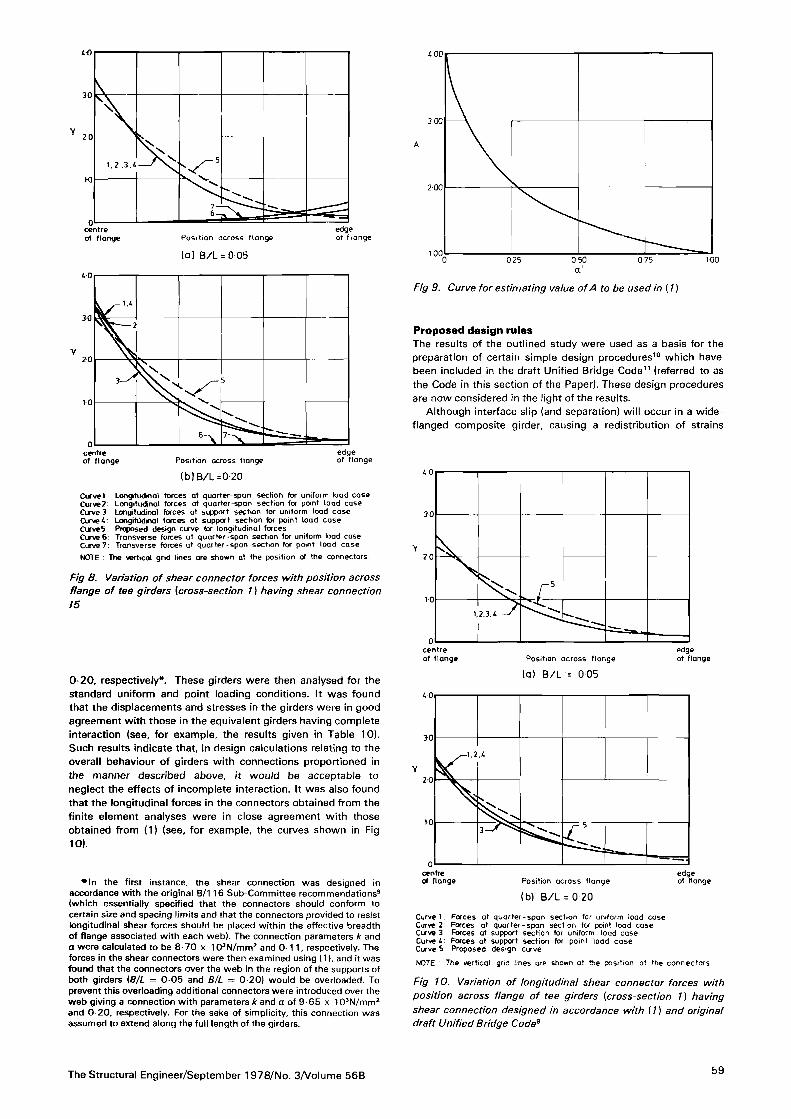
and zero slope at the flange edge. The resulting equation wasthen rearranged to give the expression for f. The curve shown inFig 9, from which A is obtained, is based on the values given inTable 9 for the girders having a BlL ratio of 0 05 and the shearconnections II to 14. To obtain the curve
, the connector forces
were multiplied by KrjKs Ks being the slip modulus of theconnector over the web.
Curves based on (1) are shown in Figs 5 to 8. It can be seenthat these curves and those obtained from the finite element
analyses are in close agreement. The equation could also beapplied to multi-web girders by treating such girders as acombination of equivalent tee girders.
As a final part of the investigation, (1) was used in
conjunction with the original recommendations made by theB/116 Sub-Committee on composite bridges9 to design a shearconnection for the girders of cross-section 1. The connection soobtained had parameters k and a of 9-65 x 103N/mm2 and
58 The Structural Engineer/September 1978/No. 3/Volume 56B
to
Y
20
20
51.2
,3,4 ' \ v
7
0centre
of flange Position across flange
(a) B/L = 0 05
edgeof flange
Y
to
l.t
302
20
N
3 5
10
0
edgecentreof flangeof flange Position across flange
(b)B/L=0-20
Curvel: Longitudinal forces at quarter-span section for untfonr load caseCufve2: Longitudinal forces at quarter-span section for point load caseCurve 3: Longitudinal forces at support section for uniform load caseDrvet'- Longitudinal forces at support section for point load caseCurveS Proposed design curve for longitudinal forcesCurve 6: Transverse forces at quarter-span section for uniform load caseCuve7: Transverse forces at quarter-span section for point load case
NOTE : The vertjcal grid lines are shown at the position of me connectors
Fig 8. Variation of shear connector forces with position acrossflange of tee girders (cross-section 1) having shear connection15
0-20, respectively*. These girders were then analysed for the
standard uniform and point loading conditions. It was foundthat the displacements and stresses in the girders were in goodagreement with those in the equivalent girders having completeinteraction (see, for example, the results given in Table 10).Such results indicate that, in design calculations relating to theoverall behaviour of girders with connections proportioned inthe manner described above. It would be acceptable toneglect the effects of incomplete interaction. It was also foundthat the longitudinal forces in the connectors obtained from thefinite element analyses were in close agreement with those
obtained from (1) (see, for example, the curves shown in Fig10).
.In the first instance, the shear connection was designed in
accordance with the original B/116 Sub-Committee recommendations9(which essentially specified that the connectors should conform tocertain size and spacing limits and that the connectors provided to resistlongitudinal shear forces should be placed within the effective breadthof flange associated with each web). The connection parameters k andH were calculated to be 8 70 x 103N/mm2 and 0 11
, respectively. Theforces in the shear connectors were then examined using (1),
and it was
found that the connectors over the web in the region of the supports ofboth girders (S/i = 0 05 and B/L = 0 20) would be overloaded. Toprevent this overloading additional connectors were introduced over theweb giving a connection with parameters Ar and a of 9 6 5 x 10³N/mm2and 0-20, respectively. For the sake of simplicity, this connection wasassumed to extend along the full length of the girders.
300
A
200
1000 050 1000-25 0 75
a
Fig 9. Curve for estimating value of A to be used in{l)
Proposed design rulesThe results of the outlined study were used as a basis for thepreparation of certain simple design procedures10 which havebeen included in the draft Unified Bridge Code11 (referred to asthe Code in this section of the Paper). These design proceduresare now considered in the light of the results.
Although interface slip (and separation) will occur in a wide-flanged composite girder, causing a redistribution of strains
Y
to
30
20
5
I-to
1,2
.3.t
0centre
of flange Position across flange
la) B/L = 005
edgeof flange
4 0
Y
30
1.2
.t
20
103
0
centreof flange Position across flange
lb) B/L = 0 20
edgeof flange
Curve 1: Forces at quarter-span section for uniform load caseCurve 2: Forces at quarter-span section for potnt load caseCurve 3 Forces at support section for uniform load caseCurve i: Forces at support section for point load caseCurve 5 Proposed design curve
NOTE : The vertical grid lines are shown at the posttion of the connectors.
Fig 10. Variation of longitudinal shear connector forces with
position across flange of tee girders [cross-section 1) hayingshear connection designed in accordance with (/) and originaldraft Unified Bridge Code9
The Structural Engineer/September 1978/No. 3/Volume 56B59
within the girder, the Code does not require the designer toconsider this redistribution when calculating the deflections andstresses induced by longitudinal bending of the girder. The useof this design procedure has been allowed on the assumptionthat the shear connection in the girder will satisfy certainrequirements discussed later, and is supported by the resultsgiven in Tables 4 to 6 and 10.
For the calculation of the longitudinal bending deflectionsand stresses, the recommendation has been made in the Code
that the effects of shear lag should be accounted for by usingthe effective breadth concept. Following a comparison betweenthe effective breadth ratios obtained from this study (Tables 7,
8
and 10) and those given in the Merrison design rules for steelbox girder bridges27, it was decided that the ratios given in therules should be adopted in the Code for both the concrete slaband the steel plate components of a composite flange.
For the calculation of the longitudinal bending shear forces Inthe connectors, the recommendation has been made in the
Code that use should be made of the following equation:
[W-015,(1 )2
+a15] (2)
where f is the load in a connector at a distance x from the
nearest web
gr is the design longitudinal shear per unit length of theweb at the concrete-steel interface
, calculated assum-
ing full interaction
/4 is a constant depending on a' (defined as nnjn, nwbeing the number of connectors per unit length placedwithin 200mm of the centre-line of the web and n the
total number of connectors per unit length associatedwitbthe web), and should be obtained from Fig 9
B is half the distance between the centre-line of the web
and the centre-line of the adjacent web, or thedistance between the centre-line of the web and the
free edge of the flange.
This equation is a simplified form of (1) obtained by assumingthat C can take a fixed (generally slightly conservative) value of0-15 and that all the connectors in the girder are of the sametype and size.
To limit the loss of interaction due to slip to an acceptablelevel in a girder, it was originally recommended10, on the basisof results such as those given in Tables 4 to 6 and 10, that ailthe connectors provided to resist the longitudinal bending shearforces should be placed within the effective breadth of flangeassociated with each web. However, in the Code this require-ment has been replaced by the requirement that the connectordensity in any area outside the effective breadth should not
TABLE 10-Effect of shear connector flexibility on maximumdeflections, maximum longitudinal slab and plate stresses, andmid-span slab and plate effective breadth ratios for tee girders{cross-section 1 ] having shear connection designed in accord-
ance with (') and original draft Unified Bridge Code*
Type of loadB_ Wi/Wc of hi asM tf/tf <PV<PscL
Uniform load over
length of web
Point load over web
at mid-span
0 05 100 1 00 1 01 1 00 0 990 20 1 02 0 97 1 05 1 03 0 96
005 1 00 0 99 104 1 01 0 980 20 1 02 0 95 1 10 104 0 95
exceed the least density within the effective breadth. Thisalternative requirement was preferred because It is morecompatible with the overall design approach of the Code whilestill providing safe designs12
.
From results such as those given in Table 3, it was
concluded10 that In the regions of a girder where the longi-tudinal bending moment is such that the concrete slab cracks,the steel reinforcement could be taken as contributing to thesection modulus (providing a suitable effective breadth is takenfor this purpose13), and the forces in the shear connectors couldbe predicted using (2) assuming shear flow only takes placebetween the steel plate and the steel reinforcement. However,in the Code it has been recommended that the shear flow
should be calculated assuming the slab to be uncracked(regardless of whether the slab is assumed to be cracked for thedetermination of the moments on the section) because of the
uncertainties concerning the extent of cracking and thestrength of connectors embedded in cracked concrete.
Conclusion
The details have been given of a numerical study of the elasticlongitudinal bending behaviour of box girders having widecomposite flanges. The results of this study highlighted theneed for Codes of Practice to include design information on thestiffness and distribution requirements of the connectors In
composite box girders. Accordingly, appropriate guidance,discussed herein In the light of the results of the study, has beenincluded in the draft Unified Bridge Code.
AcknowledgementThe work described in this Paper was sponsored by theDepartment of the Environment.
References
1. Clarke, J. L, and Morley, C. T. 'Steel-concrete composite plateswith flexible shear connectors'
. Proceedings of the Institution ofCivil Engineers, Vol. 53, Part 2, December 1972, p. 557
2. Moffatt, K. R., and Dowling, P. J. 'Parametric study on the shear lag
phenomenon in steel box girder bridges', CESLIC Report BG17,London, Engineering Structures Laboratories, Imperial College ofScience and Technology, 1972
3. British Standards. CPIW: Composite construction in structuralsteel and concrete. Part 2: Beams for bridges
'
, London, British
Standards Institution, 19674
. Balakrishnan, S. The behaviour of composite steel and concretebeams with welded stud shear connectors', PhD thesis. Universityof London. 1963
5. Moffatt, K. R., and Lim, P. T. K. Finite element analysis ofcomposite box girder bridges having complete or incompleteinteraction', Proceedings of the Institution of Civil Engineers,
Vol.
61, Part 2, March 1976, p. 16
. Chapman, J. C. The behaviour of composite beams in steel andconcrete
'
. The Structural Engineer, Vol. 42, April 1964, p. 1157
. Committee of Inquiry into the Basis of Design and Method ofErection of Steel Box Girder Bridges. Interim design rules',London, Department of the Environment.
19738
. Moffatt, K. R., and Dowling, P. J. Shear lag in steel box girderbridges'. The Structural Engineer, Vol. 53, October 1975, p. 439
9. British Standards. Unified Bridge Code, Part 5: The design of
composite bridges. (Draft)'
, London, British Standards Institution.
197510. Moffatt
, K. R. The longitudinal bending behaviour of compositebox girder bridges having incomplete Interaction', CESLIC ReportCBI, London, Engineering Structures Laboratories, Imperial Collegeof Science and Technology, 1976
11. British Standards. Unified Bridge Code. Part 5: The design ofcomposite bridges. (Draft)
'
, London, British Standards Institution,
1976
12. Buckby, R. J., and Johnson, R. P. Private communication13. Moffatt, K. R., and Dowling, P. J. 'Distribution of stresses in
cracked reinforced concrete tension flanges of bridge girders'
(In
preparation)
60 The Structural Engineer/September 1978/No. 3/Volume 56B