the launch dynamics of supersonic projectiles
TRANSCRIPT

The Launch Dynamics of Supersonic Projectiles
C. K. Muthukumaran1
Department of Aerospace, Indian Institute of Space Science and Technology, Trivandrum, Kerala-695547
G. Rajesh2†
Dept. of Mechanical and Automotive Engineering, Keimyung University, 1095 Shindang Dong, Dalseo-Gu, Daegu-
704-701, SOUTH KOREA
H. D. Kim3
School of Mechanical Engineering, Andong National University, SOUTH KOREA,
The aerodynamics of projectiles launched from barrels of various devices is quite complicated due to its
interactions with the unsteady flow field around it. A computational study using a moving grid method is
performed here to analyze various fluid dynamic phenomena in the near field of a gun, such as, the projectile-
shock wave interactions and interactions between the flow structures and the aerodynamic characteristics of
the projectile when it passes through various flow interfaces. Cylindrical and conical projectiles have been
employed to study such interactions and the fluid dynamics of the flow fields. The aerodynamic
characteristics of the projectile are hardly affected by the projectile configuration during the process of the
projectile overtaking the primary blast wave for small Mach numbers. However, it is noticed that the
projectile configurations do affect the unsteady flow structures before overtaking and hence the unsteady
drag coefficient for the conical projectile shows considerable variation from that of the cylindrical projectile.
The projectile aerodynamic characteristics during the interaction with the secondary shock wave are also
analyzed in detail. It is observed that the change in the characteristics of the secondary shock wave during the
interaction is fundamentally different for different projectile configurations. Both inviscid and viscous
simulations were carried out to study the projectile aerodynamics and the fluid dynamics. Though the effect
of the viscosity on the projectile aerodynamic characteristics is not significant, the viscosity greatly affects the
unsteady flow structures around the projectile.
____________________________
1 Research Scholar, Department of Aerospace, Indian Institute of Space Science and Technology, Trivandrum,
Kerala-695547
2†
Corresponding Author, Assistant Professor, Dept. of Mechanical and Automotive Engineering, Keimyung
University, 1095 Dalgubeoldaero Dalseo-Gu, Daegu 704-701, SOUTH KOREA.
3Professor, School of Mechanical Engineering, Andong National University, SOUTH KOREA,

Nomenclature
A = Projected frontal area of the projectiles.
a = Speed of sound, m/s.
Cd = Coefficient of drag.
D = Drag force, N.
M = Mach number.
Mp1 = Projectile Mach number relative to still air.
Mp2 = Projectile Mach number relative to flow behind the moving shock wave.
Ms = Shock wave Mach number at the launch tube exit, assumed parameter.
P = Pressure, N/m2.
t = Time, ms.
u = Velocity, m/s.
r = Density, kg/m3.
γ
=
Ratio of specific heats.
Subscript
P = Projectile.
S = Shock wave.
1,2 = Downstream and upstream of the moving shock wave.
I. Introduction
The unsteady flow-fields induced by the projectile when it is launched from a barrel attracted attention of many
researchers since it involve various complicated fluid dynamic processes associated with its motion1-9
. The primary
flow disturbances which make the flow field quite unsteady and complex are the flow interfaces in the primary blast
wave10-13
and its interactions14
. On the other hand, there are projectile flow-field interactions which affect the flight
stability of the moving projectile in the flow field. Depending on the Mach number of the jet exiting from the launch
tube ahead of the projectile, a secondary shock wave may form behind the primary blast wave14
. The projectile
interacts with the secondary shock wave while it is moving towards the primary blast wave resulting in a drastic

change in its aerodynamic characteristics. Another major interaction is the projectile primary blast wave interaction
when the projectile catches up the primary blast wave and overtakes it. Later the flow field becomes more
complicated when the secondary blast wave overtakes the projectile and interacts with the primary blast wave. These
consecutive interactions lead to the so called projectile overtaking problem3 which has a significant influence on the
unsteady aerodynamics characteristics of the projectiles in such flow fields. In addition to these, there are various
flow-wave interactions in the flow field which may have coupled effects on the aerodynamic characteristics of the
projectile.
Jiang et al1 have performed a computational analysis to study the fluid dynamics of a moving cylindrical
projectile in an unsteady inviscid flow field. They noticed that the interaction between primary blast wave and bow
shock wave generated due to the projectile movement in the unsteady flow field is strongly dependent on the
projectile speed. Though the fluid dynamics of the flow field was fairly explained in their work, the aerodynamics
associated with the flying projectile in the near field has not been addressed. Later, Jiang2
studied the effect of
friction between the projectile wall and the launch tube wall on the wave dynamic processes. He concluded from his
numerical results that when the pressure behind the projectile is higher, not only the leading shock of the second
blast overtakes the projectile, but the gas behind the projectile does so, resulting in complex wave dynamic
processes. He also found that there is a significant increase in the acceleration of the projectile due to this high
pressure.
Watanabe3 studied the fluid dynamics associated with the projectile overtaking problem. They used the one-
dimensional theory to analyze various overtaking criteria. They argued that the possible overtaking can be either
subsonic or supersonic, depending on projectile relative Mach number.
A computational study on the projectile overtaking a blast wave was performed by Rajesh et al4. Their results
show that the projectile flow field cannot be categorized based on the relative projectile Mach number, as the Mach
number of the blast wave is continuously changing. It is also shown that the aerodynamic characteristics of the
projectile are hardly affected by the overtaking process for smaller blast wave Mach numbers as the blast wave will
become weak by the time it is overtaken by the projectile. They noticed that the projectile drag coefficient is greatly
affected by the unsteady flow structures than the overtaking process. There have been studies to understand the flow
field characteristics in the near field of a ballistic range by some researchers5-7
. They have simulated the flow fields
and estimated the unsteady drag coefficients for simple conical shaped projectiles through inviscid simulations.

Schmidt and Shear8 visualized the flow unsteady projectile flow fields using optical methods. Also there have been
analytical studies9 to predict the flow behavior and the aerodynamics in such flow fields.
Some researchers studied the interaction of various shaped solid objects with the shock waves in steady flow
fields15-17
. Bryson and Gross15
investigated the interaction of the strong shocks by solid objects of various shapes
like cones, cylinders and the spheres in steady flow fields. They found that the experimental results have good
agreement with the diffraction theory proposed by whitham16
. Their experiments showed that the cylinders and the
spheres qualitatively have the same kind of interaction pattern.
The computations carried out so far have mainly been inviscid which could hardly capture the actual fluid
dynamics of such flow fields. For example, the diffusion of slip lines present in the flow field due to the viscous
effect, which may have a deterministic effect on the flow field and projectile aerodynamic characteristics14
.
Moreover, the shock wave-boundary layer interaction is of great importance in such flow fields which may affect
the projectile aerodynamic characteristics significantly. Viscous simulations have been carried out by Ahmadikia
and Shirani18
to study the axi-symmetric projectile overtaking problem at transonic and supersonic conditions. Their
results show that during the time the projectile overtakes the moving shock wave, the drag force decreases and even
becomes negative possibly due to the pressure difference across the shock wave. They also observed that the
pressure distribution on the projectile changes when the projectile overtakes the moving shock. However, in their
work, they have not considered the blast wave attenuation and its effect on the projectile overtaking problem. In the
experimental studies conducted by Sun and Takayama10, 14
on the shock diffraction in the absence of projectile, it is
observed that the viscosity does not affect either the shock structure or the threshold value of the initial blast wave
Mach number for the shock diffraction to occur. However, it is found that viscosity affects the structure of the slip
lines and the flow field near the wall. Even though there were many attempts to investigate the fluid dynamic
phenomena in the near field, most the results have been rather isolated and ambiguously conjectured.
This work here is hence aimed at capturing the fluid dynamics and aerodynamics of the unsteady projectile flow
field dynamics in the near field of a launch tube. Two projectile configurations have been employed to study the
launch dynamics. A moving grid method is employed to computationally simulate the flow fields. The computations
have been performed for various projectile and blast wave Mach numbers. Both inviscid and viscous simulations
have been carried out to depict the real flow field features in the vicinity of the launch tube.

II. Computational methodology
The computational study has been performed using a commercial software CFD-FASTRAN, which makes use of
density-based finite volume method that solves the two-dimensional axi-symmetric Euler equations for inviscid
simulation19
. For viscous simulations, the Navier-Stokes equations with appropriate turbulence modeling are solved.
Standard k-Epsilon model is used to model the turbulence. It is a two equation model based on Launder and
Spalding (1974) to model the turbulence20
. This equations model the turbulent kinetic energy and turbulent
dissipation rate19, 21
. The domain is discretized using structural chimera mesh system. For simulating the projectile
motion, the chimera mesh scheme allows the overlapping of one zone over the other. The communication between
the chimera cells and the overlapping cells is established through a tri-linear interpolation19
. The projectile is
identified as the moving body with six degrees of freedom. The projectile motion is modeled with Euler’s equations
of motion which is numerically solved at every time step and it requires the physical information of the projectile
such as mass and moment of inertia. The forces and the moments are supplied by the flow solver for the motion
model. The position, velocity and acceleration at the next time instants are estimated using six degrees of freedom
algorithm based on Euler’s equation of motion. The projectile has length of 50 mm, diameter of 20 mm, mass of 50
grams and the half-cone angle for the conical projectile is 30o. Since CFD-FASTRAN simulates any axisymmetric
problem as a 4o
sector of the entire domain, and the mass of the projectile sector is 5.55 E-4 kg and the three
principal components of moment of inertia are Ixx=2.78E-8 kg-m2, Iyy=Izz=1.296E-7 kg-m
2. The gas used in the
simulations is air with value of specific heat ratio of 1.4.
A. Computational domain and boundary conditions
The computational domain, the boundary condition and the configuration of the projectiles for the present study
are illustrated in Fig.1. The computational domain and the conditions that are used here are the same as that used by
Rajesh et al4.
The solver uses Van Leer’s flux vector splitting scheme for spatial discretization which is of first order accuracy.
The spatial accuracy of the scheme is increased to higher orders with the use of Osher-Chakravarthy flux limiter22
.
The time integration is carried out using point Jacobi fully implicit scheme.

Fig 1: Computational domain, boundary conditions and Projectile configurations.
The inflow/outflow boundary conditions with pressure and temperature values of standard atmosphere used at
the far fields are suitable for representing far-field boundary condition for external flow problems. For supersonic
outflows, the values of the variables at boundary are extrapolated from the interior and the boundary does not affect
the upstream flow conditions. The far-fields are given at a distances of 210 mm from the projectile. This distance
has been finalized after having observed that no strong wave reaches this boundary in the near-field, in many initial
simulations. Initially the moving shock wave at the exit of the launch tube is assumed to have a Mach number Ms.
This Mach number is one of the parameters of the study and so the computational model does not include the effects
of expansion waves moving into the launch tube, after projectile exit, and the resulting modulation of launch tube
blow down; rather the outflow from the launch is an assumed parameter.
The projectile is kept inside at a distance of 50 mm behind the shock wave. The velocity of the projectile and the
flows ahead and behind the projectile are assumed to be in the same direction and magnitude of that of the
downstream flow behind the moving shock wave which is at the exit of the launch tube. This assumption leads to the
condition that the projectile base pressure during its travel in the launch tube is constant. However, in a real gas gun
with a chambrage, an unsteady shockwave due to the diaphragm rupture is moving into the launch tube and gets
reflected on the projectile base. Moreover, an expansion can also be initiated due to the sudden acceleration of the
projectile. The projectile experiences drastic fluctuations in the acceleration due to multiple reflections owing to
these wave excursions. However, it has previously been observed23
that the fluctuations in the projectile base
pressure damp out very fast and the velocity doesn’t seem to be affected greatly5. This is dependent on many factors
such as the diaphragm rupture pressure, area ratio of the pump tube to launch tube, projectile mass and diameter, and
the type of the gas, etc23, 24
. The projectile mass used here is 50g and hence the possibility of drastic fluctuations in

the acceleration due to the wave reflections on its base may be considerably reduced due to the inertia effects and
may not affect the fluid dynamic phenomena in the near field.
Based on the above arguments, it is reasonable to assume that the base pressure on the projectile is constant, and
temperature and pressure values of the inlet boundary condition of the launch tube are same as that of the flow
conditions behind the projectile. Overset boundary conditions are assigned to the interface boundaries between
chimera mesh and the background mesh. Adiabatic wall boundary conditions are given to the launch tube walls and
the walls of the projectile.
B. Grid and time independence study
In the case of inviscid simulation, the same grid system and time step as that of Rajesh et al4 were employed.
Fig.2a shows the validation of the numerical scheme used by Rajesh et al with a particular case from Jiang etal1 of
which the shock wave at the launch tube exit (Ms) is 3.0. The comparison of the results shows that all the fluid
dynamic phenomena are well captured by the numerical scheme employed.
In order to determine the optimum mesh size and the time step size for viscous cases, the time and grid
independence studies have been performed as shown in Figs. 2b and 2c. For the viscous analyses, the grid
independence study has been performed with the number of cells of 460,000, 300,000 and 150,000 for the case of
Mp1=1.25. The time independence study has been performed with time steps of 2E-9, 3.5E-9 and 6.5E-9 for the case
of Mp1=1.25.
The acceleration history of the projectile is shown for various time steps in Fig.2a and for various numbers of
cells in Fig. 2b. There are hardly any variations in the plots. Hence, for lower blast wave Mach numbers, the time
step chosen was 3.5E-9 second and for higher Mach numbers the chosen time step was 2E-9. This is to assure the
stability of the flow solver which is found to become degrade when higher Mach numbers are chosen. Similarly, the
number of cells chosen for all the Mach numbers is 460,000.

Jiang, et al., (1998) – Numerical Schlieren (Ref.1)
Mp = 2.2, mp=50 gm, t = 0.312 ms
P
Rajesh et al (2008) – Iso-density contours(Ref. 4)
PBW
Bow shock
Vortex
Focusing shockwave
Supersonic jet
Mach disc
Vortex
Fig. 2.a: Comparison of iso-density contours with numerical schlieren.
(a) (b)
Fig. 2.b: Time independence study c: Grid independence study.

III. Results and discussions
A. The projectile overtaking phenomenon-revisited4
There are two distinct flow regimes in the launch dynamics based on the overtaking phenomenon; one is the
possible overtaking condition and the other being impossible overtaking condition. The possible overtaking is
further classified in to supersonic overtaking and subsonic overtaking condition. When relative Mach number Mp2 is
greater than 1.0, the projectile is moving supersonically relative to the flow behind the precursor shock wave with its
Mach number Ms. Meanwhile, when Mp2 is less than 1.0, the projectile is moving subsonic with respect to the flow
behind the blast wave. The conditions in which Mp2 is greater than 1.0 or less than 1.0 are referred to as supersonic
and subsonic overtaking conditions, respectively. If the projectile Mach number is less than the blast-wave Mach
number (Mp1<Ms), the projectile cannot overtake the blast wave. This is known as the impossible overtaking
condition4.
The main characteristic of the supersonic overtaking condition is that the disturbance due to the projectile motion
cannot travel upstream and affect the blast wave. Moreover, in supersonic overtaking condition, there will be a
standing shock wave in front of the projectile. However, in case of subsonic overtaking condition, the projectile
travels at subsonic velocity behind the blast wave and the disturbance wave due to the projectile motion may affect
the blast wave ahead. In real situations, the blast wave attenuates faster and the projectile relative velocity increases
to supersonic condition and the subsonic overtaking condition may not happen in most of the cases.
B. Projectile aerodynamic characteristics - inviscid flow
The acceleration histories of the cylindrical and the conical projectiles for both the inviscid and viscous cases are
analyzed for various Mach numbers ranging from Ms=1.4 to Ms=3.0. Figure 3a shows the typical acceleration
histories of the projectiles for the Mach numbers Ms=2.0. The acceleration history of the cylindrical projectile
passing through unsteady flow structures for various Mach numbers is discussed in detail for the inviscid case in
Rajesh et al4. Various state points are marked in the Fig. 3 based on the projectile-flow field interactions to bring out
the salient features of the aerodynamics characteristics of the projectile. In order to investigate configuration effects
on the projectile aerodynamic characteristics, the drag coefficient histories of the cylindrical and conical projectiles
are computed and compared, where the drag coefficient (Cd) is defined4as
pp
dAMp
DC
2
11
2
Where D is the drag force, is the ratio of specific heats, P1 is the ambient pressure, Mp1 is the projectile Mach
number relative to ambient conditions, Ap is the projected frontal area of the projectile.
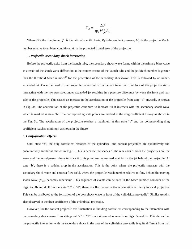
1. Projectile-secondary shock interaction
Before the projectile exits from the launch tube, the secondary shock wave forms with in the primary blast wave
as a result of the shock wave diffraction at the convex corner of the launch tube and the jet Mach number is greater
than the threshold Mach number14
for the generation of the secondary shockwave. This is followed by an under-
expanded jet. Once the head of the projectile comes out of the launch tube, the front face of the projectile starts
interacting with the low pressure, under expanded jet resulting in a pressure difference between the front and rear
side of the projectile. This causes an increase in the acceleration of the projectile from state “a” onwards, as shown
in Fig. 3a. The acceleration of the projectile continues to increase till it interacts with the secondary shock wave
which is marked as state “b”. The corresponding state points are marked in the drag coefficient history as shown in
the Fig. 3b. The acceleration of the projectile reaches a maximum at this state “b” and the corresponding drag
coefficient reaches minimum as shown in the figure.
a. Configuration effects
Until state “b”, the drag coefficient histories of the cylindrical and conical projectiles are qualitatively and
quantitatively similar as shown in Fig. 3. This is because the shapes of the rear ends of both the projectiles are the
same and the aerodynamic characteristics till this point are determined mainly by the jet behind the projectile. At
state “b”, there is a sudden drop in the acceleration. This is the point where the projectile interacts with the
secondary shock wave and enters a flow field, where the projectile Mach number relative to flow behind the moving
shock wave (Mp2) becomes supersonic. This sequence of events can be seen in the Mach number contours of the
Figs. 4a, 4b and 4c.From the state “c” to “d”, there is a fluctuation in the acceleration of the cylindrical projectile.
This can be attributed to the formation of the bow shock wave in front of the cylindrical projectile4. Similar trend is
also observed in the drag coefficient of the cylindrical projectile.
However, for the conical projectile this fluctuation in the drag coefficient corresponding to the interaction with
the secondary shock wave from state point “c” to “d” is not observed as seen from Figs. 3a and 3b. This shows that
the projectile interaction with the secondary shock in the case of the cylindrical projectile is quite different from that

of the conical projectile. This is due to the aerodynamic shape of the conical projectile and its effect on the flow
field. This effect can be clearly seen in Figs. 4b and 4c where the contours of the projectile Mach numbers are
shown. Similar trends as of those explained above are observed in the acceleration and Cd curves of Ms=2.5and are
shown in Figs. 5a and 5b. The corresponding Mach contours are shown in Fig. 6.
(a) Acceleration history (b) Drag coefficient history
Fig. 3: Acceleration and drag coefficient histories of the cylindrical and conical projectiles for inviscid and
viscous simulations for Mach number Ms=2.0 and Mp1=1.25.
(a) (b)

(c) (d)
(e)
Fig. 4: Mach contours for MP1=1.25 and Ms=2. Mach number scale range: 0-4. The axial and the radial
dimensions of the computational space are 725 mm and 210 mm.

(a) Acceleration history (b) Drag coefficient history
Fig. 5: Acceleration and drag coefficient histories of the cylindrical and conical projectiles for inviscid and
viscous simulations for Mach number Ms=2.5 and Mp1=1.75.
(a) (b)

(c) (d)
(fe)
Fig. 6: Mach contours for MP1=1.75 and Ms=2.5. Mach number scale range: 0-5. The axial and the radial
dimensions of the computational space are 725 mm and 210 mm.

(a) Acceleration history (b) Drag coefficient history
Fig. 7: Acceleration and drag coefficient histories of the cylindrical and conical projectiles of inviscid and
viscous simulations for Mach numbers Ms=3.0 and Mp1=2.2.
The smooth interaction between the conical projectile and the secondary shock wave reveals the absence of
excursion of waves when the projectile is heading towards the bow shock wave, as in the case of a cylindrical
projectile7. From the state “e” onwards, the projectiles undergo a steady deceleration. This is due to the fact that the
driving force from the jet in the secondary blast wave diminishes as the projectile moved sufficiently far from the
launch tube exit. It can also be observed that the cylindrical projectile decelerates faster than the conical projectile.
This verifies that the strength of the bow shock wave being developed in front of the cylindrical projectile is higher
that of the conical projectile.
After carefully examining the projectile-wave interaction within the blast wave, it is noted that a more detailed
analysis of this interaction and its effect on the projectile overtaking will be worthwhile. The interaction of projectile
with the secondary shock wave is the point where the classification of the flow fields based on the relative projectile
Mach number becomes important. When the projectile passes through the secondary shock wave, the relative
projectile Mach number increases to the supersonic state. It is noticed that during the projectile-secondary shock
wave interaction, the dynamics of the shock wave is highly dependent on the configuration of the projectile. This
can be clearly seen from the Figs. 4b and 6b. For the case of cylindrical projectile the shock wave preserves its shape
until the interaction. But for the conical projectile, the characteristics of the secondary shock wave change as it is

approached by the conical face of the projectile. This is mainly due to the turning of the flow field in the vicinity of
the conical face of the projectile. This causes the normal shock wave to evolve as an attached oblique shock wave in
order to meet the downstream flow conditions, provided the relative Mach number is large enough to produce an
attached oblique shock wave for the half angle of the cone.
b. Mach number effects.
The Mach number decides the nature of the interaction between the projectile and the secondary shock wave. It
is observed for the cylindrical projectile that the higher the Mach number, the stronger the variation in the drag
coefficient of the projectile. This can be clearly seen through Figs. 3b, 5b, 7b that the variation in Cd is more in the
case of Ms=3.0 compared to that of Ms=2.5 and Ms=2.0 However, for the case of conical projectile, the increase in
the Mach number does not seem to affect the drag coefficient much during the interaction as seen in the figure 7b.
2. Projectile overtaking process.
When the cylindrical projectile is overtaking the blast wave, the bow shock wave in front of the projectile
interacts with the blast wave and forms the familiar triple point on either side of the projectile. The overtaking
phenomenon starts at state “f” where the bow shock wave in front of the projectile just starts interacting with the
blast wave which is marked in Figs. 3a and 3b. This is followed by a distinct triple point formation where the
fluctuations in the projectile drag coefficient are very small. This is probably due to a weakened blast wave owing to
the attenuation of the blast wave to an extent where the pressure jump across the wave is quite smaller than that
needed to create a drastic fluctuation in the drag characteristics of the projectile. This is in contrast with Watanabe’s3
results where the blast wave maintains a constant strength throughout the overtaking process. In real situations as
described here, the blast wave strength is diminishing rapidly and hence it alters the flow conditions behind the blast
wave. This leads the only possible overtaking condition to be supersonic as the relative projectile Mach number has
reached a value greater than 1 and is still increasing. It is also observed in the present simulations that the overtaking
phenomenon does not seem to greatly affect the aerodynamic characteristics of the projectile for the Mach numbers
under consideration.

a. Mach number and configuration effects.
In Figs. 3b, 5b corresponds to Ms=2.0 and Ms=2.5, it is seen that there are no significant variations in the drag
coefficients of both the projectiles during the overtaking process. However, in Fig. 7b, where the projectile drag
coefficient history is plotted for Ms=3.0, there is a significant variation seen during the overtaking process in the
case of the cylindrical projectile. This is due to the fact that for higher Mach numbers, the blast wave attenuation
does not significantly weaken the pressure jump across the blast wave at least in the near field. It can then be
inferred that, for higher Mach numbers, the overtaking process affects the projectile aerodynamic characteristics
greatly compared to the unsteady flow structures behind the blast wave. It is also seen that this fluctuation in the
drag coefficient at the time of overtaking is not observed in the case of the conical projectile, compared to the case
of cylindrical projectile. The variation in the drag coefficient in the case of the cylindrical projectile can be attributed
to the excursion of the compression waves between the bow shock and the front surface of the cylindrical projectile,
which on interaction with the blast wave, strengthen the latter and creates a large pressure jump. On the other hand,
this excursion mechanism is absent in the case of the conical projectile due to its aerodynamic shape and there will
be a smooth interaction with the blast wave and hence the projectile drag coefficient will not be affected greatly.
3. Projectile overtaking criteria
a. x-t-diagrams:
To identify the projectile blast wave motions and the overtaking process, the x – t diagrams are plotted and
shown in Fig. 8a, and 8b. The x-t diagrams of the projectile are constructed plotting the path of the tip of the
projectiles with time. For the cylindrical projectile, the tip of the projectile never meets with the path of the blast
wave as there is shock stand-off distance. This is true for a detached shock on the conical projectile too. The
overtaking point in this case is defined as the merging of the bow shock/detached shock with the precursor
shockwave. On the other hand, the overtaking point of a conical projectile is the point at which the tip of the
projectile and the attached shockwave meets with the precursor shockwave. The numerical values for overtaking
time shown in the Fig. 8 are based on these concepts. The blast wave starts from the launch tube exit and the
projectile tip starts at 50 mm behind the shock wave. As the time progresses, the paths of the projectile and blast
wave are converging and the point where the tip of the cylindrical projectile becomes closest to the path of the blast

wave is identified as the overtaking point and is shown in the Figs. 8a, 8b. This is due to the shock stand-off distance
in front of cylindrical projectile.
In the case of the cone, the shock wave formed in front of the projectile can be attached or detached depending
on the critical Mach number Mcr for the projectile half cone angle θmax. If the relative projectile Mach number is less
than the critical Mach number Mcr, the shock wave is detached. This is particularly true for Ms=2.0 where Mp1=1.25.
It can be seen that the shock wave formed in front of the conical projectile is a detached one and the shock stand-off
distance is identified from the x-t diagram. However, the shock stand-off distance for the cone is much smaller
compared to that of the cylindrical projectile. For the attached shockwaves, the overtaking point is the point at which
the tip of the cone meets with the precursor shockwave path. The overtaking points given in terms of milliseconds in
the plots are based on the above concepts. From the Figs. 8a and 8b, it is clear that the configuration does not affect
the overtaking path except that the bow shock wave standoff distance for the cylinder is much larger than that of the
cone.
b. Mach number and configuration effects
To get the possible overtaking regimes of the projectile at various Mach numbers, the variations of Ms and Mp2
are plotted against time in Figs. 9a-b. It clarifies the effect of the attenuating blast wave on the overtaking process. It
can be seen that during the whole overtaking process, the blast wave Mach number is varying from an impossible
overtaking (Mp1<Ms) condition to possible one (Mp1>Ms)4. The overtaking is impossible until time t1 for the case of
Ms=3 and time t2 for the case of Ms=2.5 and time t3 for the case of Ms=2.0, since the blast wave travels faster than
the projectile in this regime, and after this time the overtaking becomes possible due to the blast wave attenuation
and consequent increase in Mp24. Overtaking is never possible for the case of Ms=1.4, Mp1=0.57 as the projectile
Mach number is always subsonic. The blast wave attenuations for conical and cylindrical projectile are
fundamentally of similar nature. The projectile Mach number does not change significantly in the near field. This
confirms that the configuration changes do not affect the overtaking regimes.

(a) Inviscid simulation, configuration effects (b) Viscous simulation, configuration effects
Fig8: x-t diagrams of the projectile and blast wave
(a) Inviscid simulation, configuration effects (b) Viscous simulation, configuration effects
Fig. 9: variation of Ms and Mp2 with respect to time

C. Viscous effects
The effects of viscosity on the flow field as well as on the projectile aerodynamics characteristics are analyzed
here. The turbulence is modeled using standard k- model along with the viscosity.
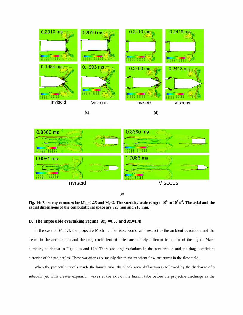
1. Projectile-flow field interaction.
A predominant feature of the viscous flows in such flow fields is the diffusion of the vorticity as seen through
the Fig. 10 a-e. In order to bring out the effect of viscosity on the flow structures clearly, the vorticity contours are
shown here. It is known that the viscous effect is a dominating factor in determining the structure of the slip lines in
such flow fields14
.
The presence of viscosity enhances the diffusion of vorticity and it alters the shock wave structures. This process
is relatively slow and its effect can be seen only at the instant when the projectile overtakes the blast wave, at a
sufficiently large distance from the launch tube exit. The diffusion of the vorticity structures during the projectile
overtaking phenomenon can be seen clearly in Fig. 10e. During the initial stages, as seen from Figs. 10 a-c, the
evolution of the slip lines seems to occur in similar manner for both inviscid and viscous cases. The diffusion is
observed in the shear layers originated from the lip of the launch tube and from the corner of the projectile wall in
viscous case.
One notable difference between the viscous and the inviscid cases is the attenuation of the shock structures
behind the projectile due to the viscous effects. This can be seen in Figs. 4e and 6e where Mach number contours are
shown. The shock structures in the jet near the secondary blast wave are significantly affected in the viscous case. It
is also noticed that the shock structures seen beneath the shear layers originating from the front corner of the
projectile in the inviscid case, are not observed in the viscous case. This confirms the fact that the viscous effects are
responsible for the vorticity diffusion which is highly influential in shaping the velocity fields and hence the shock
structures. This is clear in Fig. 10e also, where it is seen that the shock structures are significantly altered by the
diffusion of vorticity.
a. Mach number effects.
Figures 3, 5 and 7 show the aerodynamic characteristics of the projectile of Ms=2.0, Ms=2.5 and Ms=3.0 for the
inviscid and viscous cases of both projectile configurations. For higher Mach numbers, for which the projectile
relative Mach number is supersonic with respect to the ambient condition, the aerodynamic characteristics of the
inviscid and viscous cases are similar. This shows that the viscosity hardly affects the aerodynamic characteristics of

the projectile at least for moderate Mach numbers. However, for a lower blast wave Mach number where the
projectile relative Mach number is subsonic, there are large variations in the aerodynamic characteristics of the
inviscid and viscous cases as will be discussed in the section D.
2. Projectile aerodynamic characteristics.
Regarding the aerodynamic characteristics of the moving projectile, it is observed that the viscosity plays a less
significant role in the regime of Mach numbers. The boundary layer forms over the walls of the projectile that are
responsible for the shear or viscous drag, are absent in the case of inviscid flow. On the other hand, the pressure drag
on the moving projectile is quite different from that on a steady bluff body in a wind tunnel or a projectile moving in
a steady flow field. The projectile experiences drastic pressure fluctuations locally when it goes through the intricate
flow interfaces. Hence the pressure drag is the dominant one here compared to the viscous drag in determining the
unsteady drag coefficient. This is clearly seen in projectile drag coefficient histories from the Figs. 3b, 5b, and 7b.
It can also be seen in Figs. 9a, 9b that the configuration changes do not affect the possible overtaking regimes for
the viscous case as the viscosity does not affect either the blast wave attenuation or the projectile Mach number in
the near field to a significant extent.
(a) (b)
(c) (d)
(e)
Fig. 10: Vorticity contours for MP1=1.25 and Ms=2. The vorticity scale range: -106 to 10
6 s
-1. The axial and the
radial dimensions of the computational space are 725 mm and 210 mm.
D. The impossible overtaking regime (Mp1=0.57 and Ms=1.4).
In the case of Ms=1.4, the projectile Mach number is subsonic with respect to the ambient conditions and the
trends in the acceleration and the drag coefficient histories are entirely different from that of the higher Mach
numbers, as shown in Figs. 11a and 11b. There are large variations in the acceleration and the drag coefficient
histories of the projectiles. These variations are mainly due to the transient flow structures in the flow field.
When the projectile travels inside the launch tube, the shock wave diffraction is followed by the discharge of a
subsonic jet. This creates expansion waves at the exit of the launch tube before the projectile discharge as the

subsonic jet exits to a low pressure region generated due to the shock wave diffraction. The jet is subsonic and hence
the expansion wave can travel upstream into the launch tube towards the projectile face and creates a low pressure in
front of the projectile. This pressure difference causes the acceleration of the projectile inside the launch tube itself
and this is marked as state “1” in Fig. 11 and the corresponding pressure contour is shown in Fig. 12a. Moreover, the
shock wave diffraction results in the formation of moving vortical structures with which the projectile interacts later.
(a) Acceleration history (b) Drag coefficient history
Fig. 11: Acceleration and drag coefficient histories of the cylindrical and conical projectiles for inviscid and
viscous simulations for Mach numbers Ms=1.4 and Mp1=0.57.
(a) (b) (c)

(d) (e) (f)
Fig. 12: Pressure contours of viscous simulation obtained for MP1=0.57 and Ms=1.4. The pressure scale range:
0.2 to 2.88. The axial and the radial dimensions of the computational space are 725 mm and 210 mm.
There is a significant increase in the acceleration of the projectile until its head starts coming out of the launch
tube. When the projectile head reaches the exit of the launch tube, a further low pressure is created locally near the
front face of the projectile just before it interacts with the expansion wave ahead of it. This low pressure region is
indicated in Fig. 12b. Following the low pressure formation, a high pressure build up takes place when the projectile
encounters pressure difference across the expansion wave. The duration of this process is so short that there is a
drastic decrease in the acceleration of the projectile. This process occurs between state “2” to state “3” as shown in
Fig. 11. Corresponding pressure contours are seen in Figs. 12b and 12c. The increase in the pressure in front of the
projectile can be seen in the Fig. 12c. This high pressure then creates a weak bow shock in front of the projectile as
indicated in Fig.12d. The shock wave travels along with the projectile and attenuates resulting in reduction of the
pressure drag on the projectile as indicated as state “4” in Fig. 11. During this process the acceleration of the
projectile increased from state “3” to state “4” as shown in Fig. 11. From the state “4” onwards there is uniform
pressure in front of the projectile leading to a constant acceleration till the projectile completely exits from the
launch tube and this process is marked from state “4” to state “5”.
Once the projectile exits from the launch tube, the secondary blast wave forms behind the projectile and it
sweeps over the surface of the projectile followed by the formation of low pressure region behind the rear face of the
projectile. This causes a decrease in the projectile acceleration instantly from state “5” to state “6”. Till state “6”, the
acceleration histories of the projectile show the same trend for both the viscous and inviscid simulation as seen from
Fig. 11. The drag coefficient of the projectile shows similar negative trend as that of the acceleration.

From the state “6” onwards which corresponds to the point where the projectile just starts interacting with the
moving vortical structures, there are complex interactions among the projectile and the instantaneous flow-field that
are unique for the projectile configuration and for the inviscid and viscous simulations. It can be observed in Figs.
11a and 11b that, from state “6” onwards the acceleration and Cd curves of both the projectile configurations are
completely different. This can be attributed to the effect of the configuration as well as the effect of viscosity which
plays a major role in determining the complex projectile-wave interactions in the highly transient subsonic flow
fields.
IV. Conclusions
A computational analysis was performed using a moving grid method to study the launch dynamics of
supersonic projectiles. Both inviscid and viscous simulations have been carried out to analyze the flow field. It is
revealed that the flow field contains many complicated unsteady flow structures that significantly affect the
projectile aerodynamic characteristics. The results of the study are summarized below.
1. Two major phenomena which affect the flow field and the projectile aerodynamic characteristics are the
projectile-secondary shockwave interaction, and the projectile overtaking process. It is found that the projectile
configuration significantly affects its aerodynamic characteristics during its interaction with secondary shock
wave in the unsteady flow field. At higher Mach numbers the interactions were observed to be stronger.
2. The overtaking process is always supersonic in nature owing to the attenuation of the blast wave Mach number.
Neither the projectile configuration nor the viscosity affects the projectile aerodynamic characteristics to a great
extent during the overtaking process for small blast wave Mach numbers, except in the impossible overtaking
regime. But, at higher Mach numbers, the unsteady drag coefficient of the projectile changes drastically during
the overtaking process. The change in drag coefficient during the overtaking process may seem to affect the
overall unsteady drag coefficient of the projectile and hence will have some effect on the exterior ballistics of
the projectile. This may obviously be more significant in the cylindrical projectile. However, the projectile
configuration does not seem to decide the overtaking criteria regardless of the projectile Mach number.
3. The viscosity plays a major role in determining the flow structures in the flow fields. The presence of viscosity
leads to vorticity diffusion. As a result of this, the shock patterns in the secondary blast wave are seen to be

considerably weakened. It is also seen that the viscosity and projectile configuration play a major role in
deciding the aerodynamic characteristics of the projectile in the impossible overtaking regime.
References
[1] Z. Jiang, K. Takayama, and B.W. Skews, “Numerical study on blast flow fields induced by supersonic projectiles
discharged from shock tubes,” Phys. Fluids, vol.10, No.1, 1998, pp- 277-288.
[2] Z. Jiang, “Wave dynamic processes induced by a supersonic projectile discharging from a shock tube. Phys. Fluids,”
vol.15, N0.6, 2003, pp-1665-1775.
[3] R. Watanabe, K. Fujii, and F. Higashino, “Numerical solutions of the flow around a projectile passing through a shock
wave,” AIAA paper 95-1790, 1995.
[4] G. Rajesh, H. D. Kim, T. Setoguchi, “Projectile Aerodynamics Overtaking a Shock Wave,”J. Spacecraft and Rockets,
Vol.45, No.6, 2008, pp-1251-1261.
[5] G. Rajesh, H. D. Kim, S. Matsuo, and T. Setoguchi, “A study of the unsteady projectile aerodynamics using a moving
coordinate method,” Proc. of the Institution of Mechanical Engineers(IMechE), Part G, J. Aerospace Engineering, Vol.
221, 2007.pp-691-706.
[6] Y. Takakura, F. Higashino, and S. Ogawa, “Unsteady Flow Computations on a Flying Projecile within a Ballistic
Range,” Computers & Fluids, 1998, 27(5-6), 645-650.
[7] Y. Takakura and F. Higashino, “Numerical Study on the Sonic Boom Simulator Using a Ballistic Range,” 21st
International Symposium on Shock Waves (ISSW21), AFP Houwing, Ed., Panther Publishing & Printing, pp.1085-1090,
1997.
[8] E. Schmidt and D. Shear, “Optical Measurements of Muzzle Blasts,” American Institute of Aeronautics and
Astronautics J., 1975, 13, 1086-1096.
[9] A. Merlen and A. Dyment, “Similarity and Asymptotic Analysis for Gun Firing Aerodynamics,” J. Fluid Mechanics,
1991, 225, 497-502.
[10] M. Sun and K. Takayama, “Vorticity production in shock diffraction,” J. Fluid Mechanics, vol 478, 2003, pp- 237-
256.
[11] H. D. Kim and T. Setoguchi, “Study of the Discharge of Weak Shocks from an Open End of a Duct,” Journal of sound
and Vibration, 1999, 226, 1011-1028.
[12] H. D. Kim, D. H. Lee, and T. Setoguchi, “Study of the Impulse Wave Discharged from the Exit of a Right- angle Pipe
Bend,” Journal of Sound and Vibration, 2002, 259, 1147-1161.
[13] Martin Brouillette, “Ritchmyer-Meshkov instability,” Annu. Rev. Fluid Mech. 2002. 34:445-468.
[14] M. Sun and K. Takayama, “The formation of a secondary shock wave behind a shock wave diffracting at a convex
corner,” Shock Waves, vol. 7, No. 5, 1997, pp- 287-295.
[15] A. E. Bryson and R. W. F. Gross, “Diffraction of strong shocks by cones, cylinders and spheres,” J. Fluid. Mech, vol
10, issue 01, pp-1-16, 1960.
[16] G. B. Whitham, “A new approach to problems of shock dynamics part 2. Three dimensional problem,” J. Fluid. Mech,
vol 10, issue 01, pp-1-16, 1960.
[17] R. Hillier, “Computation of shock wave diffraction at a ninety degree convex edge,” Shock waves, vol. 1, 1991, pp- 89-
98.

[18] H. Ahmadikia and E. Shirani, “Transonic and supersonic overtaking of a projectile preceding a shock wave,” Journal of
Aerospace Science and Technology, vol 2, No. 4, pp- 45-53, 2005.
[19] CFD FASTRAN Theory Manual (2010). ESI CFD Inc, Huntsville, Alabama.
[20] Launder, B. E. and Spalding, D. B.," The numerical computation of turbulent flows", Computer Methods in Applied
Mechanics and Engineering, 1974, 3(2): 269-289.
[21] Yu, S. T, Chang, C. T, Marek, C. J, “Simulations of free shear layers using a compressible k-epsilon model,” AIAA,
SAE, ASME, and ASEE, Joint Propulsion Conference, 27th,Sacramento, CA, June 24-26, 1991. 10 p.
[22] S. R. Chakravarthy and S. Osher, “A New Class of High Accuracy TVD Schemes for Hyperbolic conservation laws,”
American Institute of Aeronautics and Astronautics Paper 85-0363, 1985.
[23] G. Rajesh, R. Mishra, H. G. Kang, H. D. Kim, “Computational analysis of the compressible flow driven by a piston in a
ballistic range,” Journal of Thermal Science, 2007, Volume 16, Issue 4, pp- 360-369.
[24] G. Rajesh, H. D. Kim, T. Setoguchi, and S. Raghunathan, “Performance Analysis and Enhancement of the Ballistic
Range,” Proc. of the Institution of Mechanical Engineers (IMechE), Part G, J. Aerospace Engineering, 2007, 221(5), pp-
649-659.