the latest non-destructive inspection technologies for evaluation
TRANSCRIPT

The Latest Non-destructive Inspection Technologies for
Evaluation of Grouting Condition of Tendon Ducts in
Prestressed Concrete Beams
Toshiro KAMADA Osaka University, Japan
2-1 Yamadaoka, Suita City, Osaka 565-0871, [email protected]
ABSTRACT
This paper describes the latest non-destructive inspection technologies to evaluate grouting condition in PC bridge beams using the impact elastic wave method. A rough inspection method that applies the velocity of elastic wave propagation and a detailed inspection method that applies frequency characteristics and maximum amplitude are introduced. The results of demonstration testing on an existing PC bridges are also presented. Moreover, a flowchart of non-destructive testing of grouting condition using the impact elastic wave
method for transverse prestressing steel bars in PC beams is proposed.
Keywords. Non-destructive inspection, grouting condition, impact elastic wave method,
rough inspection, detailed inspection
INTRODUCTION
In prestressed concrete (PC) structures with a post-tensioned system, corrosion of PC steel components is prevented by employing PC grouting inside sheaths. Insufficient grouting causes corrosion of PC steel components, leading to their breakage. If a steel component breaks, it may protrude from an anchorage area as shown in Figure 1. and cause damage to third parties. Recently, there have been some reports on the breakage and protrusion of transverse prestressing steel bars in PC bridge girders (Yoshiyasu, 2009), and it is a pressing task to evaluate grouting condition properly. Moreover, the breakage of steel components
Figure 1. Protrusion of PC steel bars from an anchorage area
leads to the collapse of a bridge in the worst case. In the 1980s, there was a report of the collapse of a PC bridge in the United Kingdom caused by the corrosion of PC steel components (Woodward, 1989). Occurrence of similar phenomena is a matter of concern also in Japan. To prevent this kind of damage from occurring in Japan, it is important to conduct non-destructive inspections to investigate PC grouting condition both quantitatively
and efficiently.
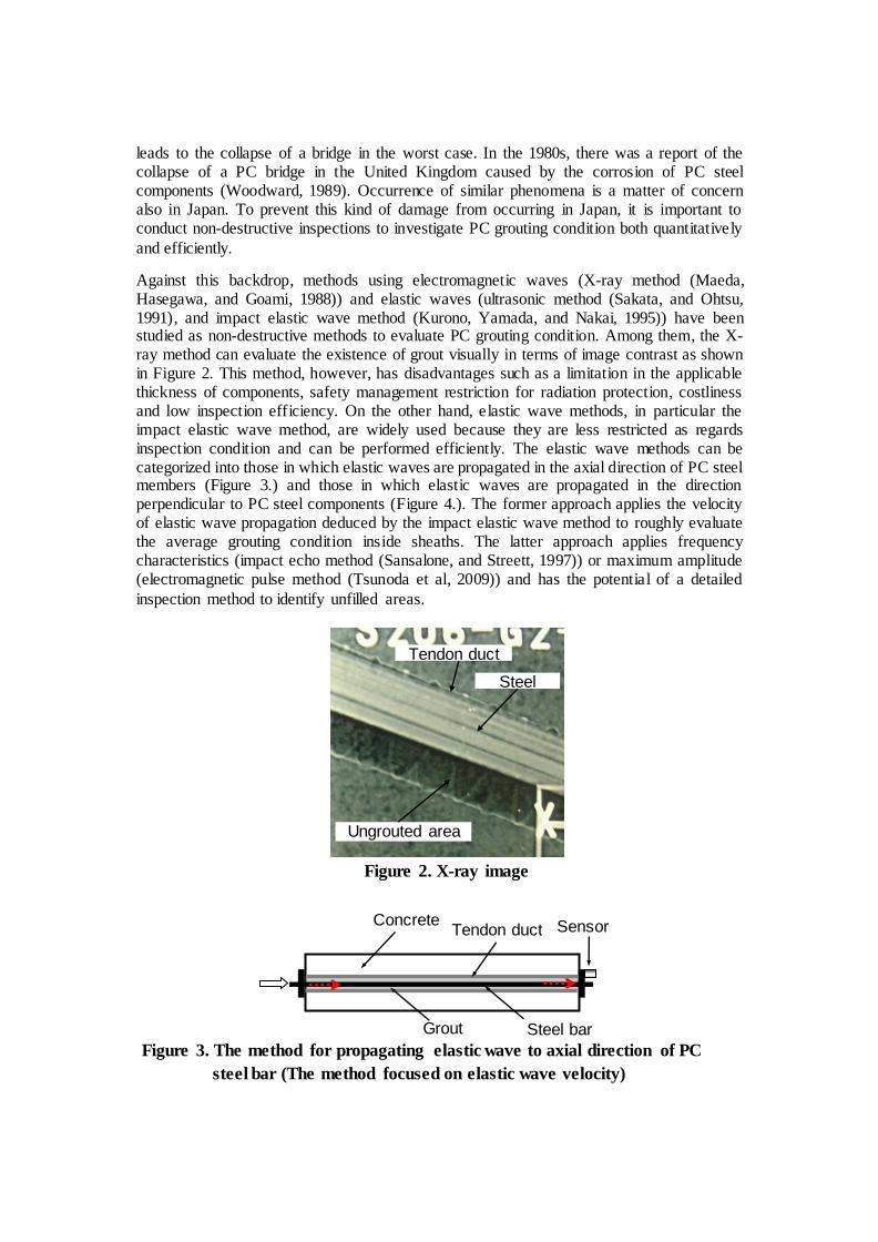
Against this backdrop, methods using electromagnetic waves (X-ray method (Maeda, Hasegawa, and Goami, 1988)) and elastic waves (ultrasonic method (Sakata, and Ohtsu, 1991), and impact elastic wave method (Kurono, Yamada, and Nakai, 1995)) have been studied as non-destructive methods to evaluate PC grouting condition. Among them, the X-ray method can evaluate the existence of grout visually in terms of image contrast as shown in Figure 2. This method, however, has disadvantages such as a limitation in the applicable thickness of components, safety management restriction for radiation protection, costliness and low inspection efficiency. On the other hand, elastic wave methods, in particular the impact elastic wave method, are widely used because they are less restricted as regards inspection condition and can be performed efficiently. The elastic wave methods can be categorized into those in which elastic waves are propagated in the axial direction of PC steel members (Figure 3.) and those in which elastic waves are propagated in the direction perpendicular to PC steel components (Figure 4.). The former approach applies the velocity of elastic wave propagation deduced by the impact elastic wave method to roughly evaluate the average grouting condition inside sheaths. The latter approach applies frequency characteristics (impact echo method (Sansalone, and Streett, 1997)) or maximum amplitude (electromagnetic pulse method (Tsunoda et al, 2009)) and has the potential of a detailed
inspection method to identify unfilled areas.
Figure 2. X-ray image
Steel
bar
Ungrouted area
Tendon duct
Figure 3. The method for propagating elastic wave to axial direction of PC
steel bar (The method focused on elastic wave velocity)
Steel bar
Tendon duct Concrete Sensor
Grout

In this paper, the author categorizes the impact elastic wave methods into (1) those that apply the velocity of elastic wave propagation, (2) those that apply frequency characteristics (impact echo method) and (3) those that apply maximum amplitude (electromagnetic pulse method). On the basis of this categorization, the author provides an overview of the latest non-destructive inspection technologies for broad and detailed inspection to evaluate PC
grouting condition.
ROUGH INSPECTION OF PC GROUTING CONDITION (NON-
DESTRUCTIVE INSPECTION TO EVALUATE AVERAGE GROUTING
CONDITION INSIDE SHEATHS)
Outline of the method that applies the velocity of elastic wave propagation and
the principle of evaluation This method uses a hammer, steel balls and the like to mechanically impact a concrete surface and detect resulting elastic waves with a sensor. The state inside the concrete can be evaluated from the velocity of wave propagation. The input elastic waves in this method are greater in energy compared with the input ultrasonic waves in ultrasonic testing and include low-frequency range elastic waves. This method is therefore
less affected by attenuation and scattering and is capable of measuring wide component areas.
Figure 5. shows the principle of evaluation of PC grouting condition. If the sheath is not filled with grout, elastic waves propagate most rapidly through the steel bar. Therefore, the apparent elastic wave velocity becomes close to the propagation velocity in a steel bar as a single unit. If the sheath is filled with grout, elastic waves propagate through the composite member consisting of the steel bar and grout; propagation velocity therefore becomes
smaller than that in the unfilled case.
:Magnetic coil
Concrete Steel bar
Tendon duct
:Impact
:Sensor
Figure 4. The method for propagating elastic wave to vertical direction of PC
steel bar (The method focused on frequency characteristic or
maximum amplitude)
Grout
Impact Impact Wave front
Figure 5. Principle for evaluation of PC grouting condition focused on
propagating velocity
(b) Grouted duct (a) Ungrouted duct

Figure 7. Impact device
Figure 6. PC girders
Example of inspection of actual PC bridge girders (Kamada et al, 2006) For transverse prestressing steel bars in PC bridge girders in use (shown in Figure 6.), the results of evaluating PC grouting condition are outlined in this section. This bridge has separate girders for each of upbound and downbound lanes, and each lane consists of four main beams, a filling part and an extended part, which are integrated into one unit with transverse prestressing steel bars. The impacting device shown in Figure 7. was used for generating elastic waves. Impact was applied to a steel bar end in the extended part (see Figure 8. (a)). To record the time of elastic wave input, a sensor was installed near the point of impact (see Figure 8. (a)). The input elastic wave was detected with sensors installed on a concrete side surface situated between the upbound and downbound lanes (see Figure 8. (b)). Figure 9. shows an example of waveform detected by each sensor. The velocity of elastic wave propagation was obtained by dividing the distance between sensors by the difference in time of wave arrival between the sensors.
Figure 8. Location of elastic wave input and sensors
(b) Location of sensor
Sensor
(a) Location of elastic wave input and
sensor
Sensor

Figure 10. Elastic wave velocity measurement results
3800
4300
4800
5300
1 2 3 4 5 6 7 8 9 10 11 12
伝搬速度(m/s)
横締め鋼棒番号
Wave v
elo
city
(m
/s)
Steel bar no.
Figure 10. shows an example of results obtained. In the steel bars whose propagation velocity exceeded 4800 m/s (shown in red in the figure), areas unfilled with grout were observed at all the drilled locations as shown in Figure 11.In the steel bars whose propagation velocity was less than 4300 m/s (shown in blue in the figure), filling with grout was confirmed. In the steel bars whose propagation velocity was intermediate (shown in yellow in the figure), areas filled and unfilled with grout were mixed. On the basis of the results of drilling investigation, grout was reintroduced to steel bars whose propagation velocity exceeded 4800 m/s, and then the velocity of wave propagation was measured again. Figure 12. compares propagation velocity before and after the re-grouting. In either case, propagation velocity became smaller after re-grouting. This indicates that the effectiveness of re-grouting can be evaluated by comparing propagation velocity before and after re-grouting.
Figure 11. Example of ungrouted duct
Tendon duct
Steel bar
時間差を読み取り伝搬速度を決定
入力側波形(はね出し部)
受信側波形(線間側)
Figure 9. Example of waveform with each sensor
Received waveform
Measure the propagation time to
determine the velocity
Input waveform

DETAILED INSPECTION OF PC GROUTING CONDITION (NON-DESTRUCTIVE INSPECTION TO DETECT AREAS UNFILLED WITH GROUT BENEATH
MEASUREMENT POINTS)
Method that applies frequency characteristics (impact echo method)
Outline of the method and the principle of evaluation In this method, as shown in Figure 13., a concrete surface is hit by a steel ball so that elastic waves are propagated through the concrete, a sensor installed on the side of the impact surface detects reflected waves from objects, and the thickness of components and the presence or absence of internal defects are
evaluated from the observed frequency characteristics.
Figure 14. shows the principle of evaluation of PC grouting condition. If a sheath is completely filled with grout, a peak corresponding to concrete slab thickness (defined as fT) appears on a frequency spectrum. If there is an area unfilled with grout, on the other hand, a peak corresponding to waves reflected from the unfilled area (fvoid) appears in addition to the
fT peak. The values of the two peaks of fT and fvoid are theoretically obtained by
fT = Cp / 2T (1)
fvoid = Cp / 2d (2)
When applying this method, the position and depth of a sheath is first investigated by the electromagnetic radar method. Substituting the estimated sheath depth into equation (2), we obtain a peak frequency value based on an assumption that there is an area unfilled with grout. Finally, a frequency spectrum is obtained by this measurement method, and if a peak appears at the theoretically predicted frequency, it is judged that there is an area unfilled with grout.
3800
4300
4800
5300
4 9 11
伝搬速度(m/s)
横締め鋼棒番号
グラウト再注入前
グラウト再注入後
Figure 12. Change of wave velocity due to grouting
grouting
Wave v
elo
city
(m
/s)
Steel bar no.
Before grouting
After grouting
Figure 13. Outline of the method focused on frequency characteristics
(Impact-Echo Method)
Elastic wave input
Sensor
Am
plit
ude
Received waveform Frequency spectrum
Am
plit
ude
Time Frequency
Wave recording device

Example of inspection of actual PC bridge girders (Kamada et al, 2006) For main cables in the PC bridge girders shown in Figure 6., PC grouting condition was evaluated by using the method that applies frequency characteristics, whose results are described here. Figure 15. shows the steel balls, sensor, amplifier and waveform collection system used in this method. Figure 16.shows measurement being conducted at the web part of a girder. Figure 17. shows an example of measurement results. The arrows in the figure indicate the theoretical fT values deduced from equation (1), and the broken lines indicate the theoretical fvoid values deduced from equation (2). The velocity of elastic wave propagation measured at the bridge is used in the figure. In either case of Figure 17. a peak appeared at the fT location. In the case of Figure 17. (b), there is a peak at the fvoid location in addition to the fT location. This indicates that the sheath is filled with grout in the case of Figure 17. (a), and there is an unfilled area in the case of Figure 17. (b). The estimated results were in agreement with the results of drilling investigation.
:弾性波入力
:センサ
グラウト未充填
T
d
シース
PC鋼材
周波数 (kHz)
スペクトル強度
スペクトル強度
周波数 (kHz)
fT
fT
fvoid
版厚
グラウト未充填
コンクリート
:弾性波入力
:センサ
グラウト未充填
T
d
シース
PC鋼材
周波数 (kHz)スペクトル強度
スペクトル強度
周波数 (kHz)
fT
fT
fvoid
版厚
グラウト未充填
コンクリート
Figure 14. Principle for evaluation of PC grouting condition focused on
frequency characteristics
Frequency
Am
plit
ude
Am
plit
ude
Frequency
Concrete plate
Concrete plate with void inside tendon duct
Sensor
Impact
Concrete
Tendon duct
Void Steel bar
T
d
Figure 15. Measurement system
Wave recording device
Steel balls
Sensor Amplifier

Method that applies maximum amplitude (electromagnetic pulse method)
Outline of the method and the principle of evaluation. Unlike the methods that apply the velocity and frequency characteristics of input elastic waves, the method that applies maximum amplitude uses an exciting coil to impact PC steel components in a noncontact manner. This coil consists of magnet wire winding around an electromagnetic steel plate. An instantaneous magnetic field can be created by applying pulse current to the coil. The electromagnetic force created by the magnetic field induces vibration in the magnetic materials contained in concrete. Elastic waves created by the vibration of the magnetic materials are detected by a sensor placed on the concrete surface, and the state of the magnetic materials and their interfacial defects are evaluated non-destructively from the maximum amplitude of the receiving waves (see Figure 18.).
Figure 19. shows the principle of evaluation in this method. When a sheath is filled with PC grout (see Figure 19. (a)) and pulsed electromagnetic force is applied to a concrete surface in a noncontact manner, mainly the sheath beneath the exciting coil vibrates. Because the sheath is confined by the grout, the vibration of the sheath is more or less suppressed. In addition, the PC steel bar inside the sheath hardly vibrates because of the magnetic shielding effect. In the case the sheath is not filled with grout (see Figure 19. (b)), because the sheath is not confined by grout, the vibration of the sheath is apparently greater than that of the sheath filled with grout. By detecting vibration with a sensor placed on the concrete surface and
comparing maximum amplitude values, it is possible to identify areas unfilled with PC grout.
0 10 20 30 40 50 600
0.5
1
[10-6
]
【シース上側 A 】
Frequency (kHz)
Am
plitu
de
埋設深さ100[mm]エアーガン
0 10 20 30 40 50 600
0.5
1
[10-6
]
Am
plitu
de
Frequency (kHz)
【シース下側 B 】
埋設深さ100[mm]エアーガン
0 10 20 30 40 50 600
1
2
3
[10-6
]
Am
plitu
de
Frequency (kHz)
【シース下側 C 】
埋設深さ90[mm]エアーガン
0 10 20 30 40 50 600
1
2
3
4[10
-6]
Am
plitu
de
Frequency (kHz)
【シース真上 A 】
0 10 20 30 40 50 600
1
2
3
4
5[10-6
]
Am
plitu
de
Frequency (kHz)
【シース真上 B 】
0 10 20 30 40
Am
plitu
de
Frequency (kHz)
【シース真上 C 】
周波数 (kHz)
スペクトル強度
0 10 20 30 40 50 600
0.5
1
1.5[10
-6]
Am
plitu
de
Frequency (kHz)
【シース下側 A 】
0 1020304050600
0.5
1
1.5[10-6
]
Am
plitu
de
Frequency (kHz)
【シース下側 B 】
0 10 20 30 40 50 600
0.5
1
1.5[10-6
]
Am
plitu
de
Frequency (kHz)
【シース下側 C 】
御替地架道橋PC桁インパクトエコー法実験データ (上り線耳桁 大阪方面 ケーブルC2)
Figure 17. Example of measurement results in the method
focused on frequency characteristics
0 10 20 30 40 50
周波数 (kHz)
スペクトル強度
埋設深さ110[mm]エアーガンシース上側A
0 10 20 30 40 50
埋設深さ110[mm]エアーガンシース上側B
スペクトル強度
周波数 (kHz)
0 10 20 30 40 50
周波数 (kHz)
スペクトル強度
埋設深さ110[mm]エアーガンシース上側C
0 10 20 30 40
シース真上
周波数 (kHz)
スペクトル強度
0 10 20 30 40
シース真上
スペクトル強度
周波数 (kHz)0 10 20 30 40
シース真上
スペクトル強度
周波数 (kHz)
0 10 20 30
スペクトル強度
周波数 (kHz)
シース下側
0 10 20 30 40 50
シース下側
スペクトル強度
周波数 (kHz)
0 10 20 30
御替地架道橋PC桁インパクトエコー法実験データ(上り線耳桁 東京方面 ケーブル1)
スペクトル強度
周波数 (kHz)
シース下側
(b) Depth of void 90mm
Frequency (kHz)
Am
plit
ude
(a) Depth of void 110mm
Frequency (kHz)
Figure 16. Outline of measurement using the method focused on
frequency characteristics
Steel ball
Sensor
Am
plit
ude

Example of inspection of actual PC bridge girders The PC bridge girders (transverse prestressing steel bars) investigated are of the same structural type as that shown in Photo 3. Measurements were performed at a filling part and an extended part as shown in Figure 20.An exciting coil was placed so that the lines of magnetic flux in the field become parallel to the longitudinal sheath direction. To keep a constant distance between the coil and concrete surface, a hard plastic spacer of 20 mm in thickness was attached to the coil end. Beneath the coil, a sensor to detect vibration from the sheath was placed on the concrete surface. Some results shown in Figure 21. indicate that the maximum amplitude in the extended part was smaller than that in the filling part. According to the principle of evaluation shown in Fig. 11, it is inferred that the extended part was filled with grout
Figure 19. Principle for evaluation of PC grouting condition focused on the
maximum amplitude
(a) Grouted duct
(b) Ungrouted duct
Bearing plate
Grout
Tendon duct Magnetic coil
Steel bar
Concrete Sensor
Figure 18. Outline of the method focused on the maximum amplitude
(electromagnetic pulse method)
励磁コイルセンサ
コンクリート
アンプ
定電流・定電圧発生装置
磁性体弾性波
Sensor Magnetic coil
Magnetic substance
Amplifier
Constant current and fixed voltage generator
Concrete Elastic wave

whereas the filling part was not filled with grout. The estimates given by this method were in agreement with the results of drilling investigation.
PROCEDURE OF EVALUATION OF PC GROUTING CONDITION IN PC
BRIDGE GIRDERS USING THE IMPACT ELASTIC WAVE METHOD
On the basis of the above discussions, Figure 22. shows a flowchart of non-destructive testing of
PC grouting condition using the impact elastic wave method for transverse prestressing steel bars
in PC bridge girders. First, as a rough inspection method (I), elastic waves are propagated in the
axial direction of a PC steel component to make evaluations based on propagation velocity. A
threshold value of propagation velocity to estimate the presence or absence of grout can be
determined, for example, on the basis of measurement (analysis) results on a specimen (model)
that simulates the structure to be investigated, or by investigating grouting condition at several
locations by X-ray or other devices for reference purposes. Then, if insufficient filling with grout
is suspected from the broad inspection results, elastic waves are propagated in the direction
perpendicular to PC steel components as a detailed inspection method (II) by using both or either
of the methods that apply frequency characteristics and maximum amplitude, in order to identify
the areas where filling may be insufficient. With this kind of inspection procedure, it is possible
Figure 20. Outline of measurement using the method focused on the
maximum amplitude
Magnetic coil
Spacer
Sensor
Figure 21. Example of measurement results in the method focused
on the maximum amplitude
0.0
0.2
0.4
0.6
0.8
1.0
1.2
はね出し 間詰め1 間詰め2 間詰め3
最大振幅値(V)
Interfilling1 Interfilling3 Interfilling2 Maxim
um
am
plit
ude (
V)
Ledge 0.0
0.2
0.4
0.6
0.8
1.0
1.2
はね出し 間詰め1 間詰め2 間詰め3
最大振幅値(V)

to evaluate grouting condition non-destructively without performing drilling. If a void unfilled
with grout is found by the detailed inspection, re-grouting is performed after drilling, a rough
inspection is conducted again after the grout has set, and a detailed inspection is conducted if
necessary. By repeating the above-mentioned steps, it is possible to minimize damage to
structures, detect unfilled areas efficiently, and evaluate the effectiveness of re-grouting.
Figure 22. Flowchart of PC grouting condition evaluation method
START
Input elastic waves and
measure wave velocity,V.
Determination of V under fully grouted condition, Vc.
Possibility of insufficient grouting
Drilling hole
Sound grouting
END
Re-grouting
NO
NO
YES
YES
I: Rough inspection (Focus on elastic wave velocity)
II: Detailed inspection
Detect locations and depths of steel bars by electromagnetic rader.
V > Vc
Spectrum peak at the fv oid position Relatively large maximum amplitude
(Focus on frequency characteristics or maximum amplitude)
Input elastic waves to the vertical direction of PC steel bars, and
obtain frequency spectrum or maximum amplitude.

CONCLUDING REMARKS
As latest non-destructive inspection technologies to evaluate PC grouting condition in PC bridge girders using the impact elastic wave method, the author has described a rough inspection method that applies the velocity of elastic wave propagation and a detailed inspection method that applies frequency characteristics and maximum amplitude, and presented the results of demonstration testing on a bridge actually in use. The author would be more than happy if the methods described here would be useful to streamlining maintenance work and ensuring the safety of structures in general post-tensioned PC bridges
using PC grout.
REFERENCES
Haruo Maeda, Atsushi Hasegawa, Masao Goami. (1988): Non-destructive testing of concrete structures by X-ray method, Proceedings of the symposium on durability of concrete structures, pp.109-115. (in Japanese)
Hotaru Tsunoda, Toshiro Kamada, Shinya Uchida, Kotaro Munakata and Tadashi Inaguma. (2009): Basic study on evaluation method for grouting condition in PC members with elastic waves generated by magnetic force, Proceedings of the Concrete
Structure Scenarios,JSMS, Vol.9, pp.39-44. (in Japanese) Sansalone, M. and Streett, W. B. (1997): Impact Echo, Nondestructive evaluation of
concrete and masonry, Bullbrier Press, Ithaca, NY and Jersey Shore, PA. Toshiro Kamada, Masanori Asano, Masamichi Kawashima, Shinya Uchida and Keitetsu
Rokugo.(2006): Application of impact elastic wave method for evaluation of grouting condition of tendon ducts in existing PC structures, Journal of Materials, Concrete Structures and Pavements(E), JSCE, Vol.62, No.3, pp.569-586. (in Japanese)
Woodward, R. J. (1989): Collapse of a segmental post-tensioned concrete bridge, Transportation Research Record, V. 1211, Transportation Research Board, National Research Council, pp. 38-59.
Yasunori Sakata, Masayasu Ohtsu.(1991): Evaluation of grouting condition in post tensioned PC-beam by ultrasonic spectroscopy, Proceedings of the symposium on non-destructive test method of concrete, pp.87-92. (in Japanese)
Yukihiro Kurono, Kazuo Yamada, Yuji Nakai.(1995): Fundamental study on grouting evaluation in PC slab by impact elastic wave method, Proceedings of the Japan Concrete Institute, Vol.17, No.1, pp.1175-1180. (in Japanese)
Yusuke Yoshiyasu.(2009): A case study on deterioration damage of the Himeji by-pass viaduct in Japan national route 2, Proceedings of 2009 workshop of the Kinki Development Bureau, Disaster prevention and maintenance section, No.14.(in Japanese)