the jsdr 1.0 suite (jff-sdr) software for a simple ... · with soundcard operation supporting...
TRANSCRIPT

The JSDR 1.0 suite (JFF-SDR)
Software for a simple software defined radio
with soundcard operation
supporting shortwave and fm reception
Jan van KatwijkJFF ConsultancyThe Netherlands
March 5, 2012
1
1 Introduction
jff-sdr (or JSDR) is an implementation of a set of support programs for software defined radio. Theprograms implement a basic receiver in the sdr domain: functioning, but many improvements andenhancements are possible and needed.
The set is written in C++, it was developed under Linux (recent versions of Fedora and Ubuntu,both 32 and 64 bits versions), using Qt (and Qwt) for the gui. Thanks to the portability of Qt andC++ and thanks to Mingw-32 as Windows development platform with all its libraries (e.g. portaudio),porting it to Windows turned out to be surprisingly simple (though not trivial).
The software has been tested under Windows XP, Vista, W7, Fedora 12/13/14/15,16 and Ubuntu10.04/11.10. Currently I am running Fedora-16 (32 bits), Ubuntu 11.10 (64 bits) and Windows-7 withMingw-32 on one laptop and Ubuntu-10.04 and Fedora-15 (both 64 bits) on another.
The software is being developed as a hobby project and is available as open source under theLGPL V2 and V3. It builds upon many open source libraries (e.g. Qt, Qwt, fftw3, libusb-1.0, libftdi,libsamplerate, libsndfile, libportaudio) while other existing software available under open source licenses,e.g. gmfsk and fldigi, served as source of inspiration (and some lines of code) for the various decoders.
The set contains a shortwave and an fm receiver (swreceiver resp. fmreceiver).
swreceiver The swreceiver implements:
• Control. In the current version, control for two sdr devices is integrated, i.e. the Elektor SDRcard (May 2007) (including the antenna filter extensions as described in Elektor december 2009),and the basic-PMSDR1 The Elektor supports continuous tuning between app 150K to 30M. ThePMSDR supports - through the use of the 3-d harmonic trick - continuous tuning between 100Kand 165M.
• Reading and processing of soundcard data, filtering of the data, frequency transforms of the datainto a baseband signal and displaying frequency information the the form of spectra.
• Decoding of the baseband signal:
– analog signals for the modes AM, USB, LSB, ISB and (smallband) FM,
– CW,
– digital modes:
∗ rtty,
∗ psk,
∗ navtex,
∗ mfsk,
∗ (wheather)fax,
∗ domino.
Data may pass the front end stage decimated but further unaltered, which is particularly usefulwhen an existing shortwave receiver is used to generate the program input. Furthermore, the softwaresupports dumping the unaltered input samples into a ”.wav” file, and reading ”.wav” files, processingtheir content.
Samplerates for input and output streams are frozen per run of the program. When starting theprogram from a command line, the samplerate can be set by the -S option (48000 samples), -T option(192000 samples) and -R option (96000 samples). The default samplerate is 96000 samples/second.OutputRate is 48000 in all cases.
1The 100K .. 55 Mc version is supported, the UHF extension card is not, simply because I do not own such an extensioncard.
2

fmreceiver The fmreceiver implements:
• Control. In the current version, control for the basic-PMSDR is supported. The PMSDR supports- through the use of the 3-d harmonic trick - continuous tuning between 100K and 165M.
• Reading and processing of soundcard data, filtering of the data, frequency transforms of the datainto a baseband signal and displaying frequency information the the form of spectra. Both monoand stereo signals can de decoded as well as rds decoding is supported.
As with the swreceiver, the software supports dumping the unaltered input samples into a ”.wav”file, and reading ”.wav” files, processing their content.
Samplerates for input and output streams are frozen per run of the program. When starting theprogram from a command line, the samplerate can be set by the -E option (192000 samples) and the -Foption (176400 samples). The default samplerate is 192000 samples/second. OutputRate is 0.25 timesthe inputrate, i.e. 48000 resp. 44100.
General remarks The software most likely contains errors. Although the numbers of errors foundwas exponentially decaying for the past few months, it is an illusion to assume the software to beerror-free. All kind of feedback is welcome.
This manual is a second draft, it therefore provides plenty of room for improvements: suggestionsand comments are welcome.
2 The distribution package
The distribution is in the form of a tarball. When unpacking, the following list of files and directoriesis created
• demo, a directory containing a simple program that shows the behaviour of the various filters(FIR and IIR). Its operation is fairly trivial.
• docs, the directory containing a ”.pdf” version of this document.
• filters, the directory containing all software implementing the various filters being used (IIR, FIR,and fft-based FIR).
• fmreceiver, a directory containing the source code for the FM software. The software is to be usedin conjunction with the PMSDR, but obviously, can also be used to demodulate FM signals thatare downconverted by other devices.
• INSTALLATION, a text file giving a brief overview over the build and installation process.
• jff-include.h, an include file with some system wide definitions.
• license, a copy of the license to use this material.
• README, it is a suggestion to actually read it.
• righandling, a directory containing all files for controlling the two supported rigs.
• scopes, a directory containing the files implementing the various scopes, used by the programs.
• sound, a directory containing a small demonstration program to generate sound, including aspectrum display showing the sound spectrum.
3

• sound-portaudio, a directory containing all files for handling sound, based on the portaudio library.The directory also contains the code for reading input from a file. Note that the code for writingout the samples into a file is almost trivial and in-line encoded in the main driver programs.
• swreceiver, a directory containing all files specific to the shortwave receiver. The main driverprogram is in the file called g̈ui.cpp̈, which is essentially interfacing the logic to the user interface.
• utilities, the directory containing a few, small, support functions, some of them are not even usedanymore, but may be of use in future releases or extensions.
• viterbi, the directory containing an implementation of the viterbi algorithm, used in e.g. the qpskand the mfsk decoders.
3 Description of the shortwave radio program screen
Starting the swreceiver is in Linux often just by a command line in some shell in the directory ”..../swre-ceiver/”.
$ ./swreceiver
On my laptop I am using the command
sudo ./swreceiver
since I do not always set the setuid bit when generating a new version.Under Windows, using Mingw, it requires the command:
$ ./release/swreceiver
Once the program is started, the following screen will appear
The screen shows three areas:
4

• on top: two displays, one displaying the spectrum for the whole band covered, i.e. with the widthof the selected samplerate, the second one displaying the spectrum for the baseband selected forthe decoder.
• in the middle: buttons and sliders to control the program and the associated radio device.
• on the bottom: a screen for the decoder. For each of the different decoders, a separate screen isdefined and shown upon selection of the decoder.
4 Control
4.1 Selecting input and output
The program, once started, will wait with processing data until appropriate input and output streamsstreams are selected and the start button is activated by clicking on it. Pushing the start button,however, without having selected appropriate input and output streams results in a message with arequest to set the streams properly.
The elements, indicated in the picture above, are
• selection of the input stream. Obviously, the possibilities for selection are dictated by the systemconfiguration. One additional possibility exists: selection of an input file.
• selection of the output stream. Again, the possible selections do depend on the system configura-tion.
• start button.
The rate with which the input stream is processed is indicated on the screen. In case an input file isselected (a ”.wav” file), the rate of the sample stream in the ”.wav” file is converted to the rate requiredby the program. Some of the example screens in this manual resulted from reading a file.
5

When appropriate input- and outputstreams are selected, clicking on the start button will cause theprogram to actually start reading samples from the input stream and to process these samples.
Personally, I am using an EMU-202 box (since I blew up the soundcard in my laptop with anexperiment with a one-tube receiver), which is selected for the input, while the selected sound outputis through the laptop-card.
Linux and Portaudio Linux and soundcard handling - done through Portaudio - are no real friends.The combo-boxes for the input and output streams show a lot of potential streams, most of them donot work properly. Experience shows that selecting the hardware, i.e. the ”raw” entries to the cards,or the default option does work best. Often, when opening the program quite some error messages oneither blue tooth or mixers are given, these can be ignored. The PA people are working on it.
Pulse, the apparent default sound handler in Linux environments and portaudio hate each othereven more, do not even try to select pulse as either input- or outputstreamer. I have been strugglingwith Pulse for input and output. However, I did not manage to get reasonable results, Pulse seems toprovide data in large chunks, too large to show a more or less continuous stream. Any help to addressthis is greatly appreciated.
Windows and Portaudio The combo-boxes for the input and output streams show a lot of potentialstreams. I am using the ASIO software interfacing to the Emu-202 card for input and the card of mylaptop for output. (ASIO, when used for both input and output through the EMU requires input andoutput with the same speed settings). The default configuration for Portaudio used here does not allowAsio for both input and output (code for the implementation for ASIO as both input- and output deviceis commented out in the software)
Windows/ASIO/portaudio/Emu-202 runs 192 K sampling without problems, while Linux/Alsa/portaudio/Emu-202 is limited to 96K. The FM variant of this software therefore runs only successfully under Linuxwhen handling ”.wav” input files containing prerecorded FM.
FreqFile The program, when starting, expects the file ”FreqFile” to be available in the directorywhere the program is started. In the distribution a file is standard available. This file contains thespecifications for voltage settings in the preselector for the Elektor SDR card. Since the driving softwarefor elektor is included, the file is needed. I might consider a next version of the software where thehardware (i.e. elektor or pmsdr) is a configuration option.
The FreqFile contains 4 tables, one for each preselector circuit of the preselector for the Elektor.Entries in these tables contain a frequency and a value for the voltage used to tune the preselectorcircuit in the given band to the selected frequency. When no FreqFile is present, the software will justrun after signaling the absence of the file.
4.2 Selecting a radio device
Once the program is running, it will process whatever data is read through the selected stream by theinput sampler.
Control of a radio device is as such decoupled from receiving data. Especially when using a separateprogram to control a radio, or, otherwise to limit the use of the program as backend for a radio, thereis no further need for radio control.
6

When selecting a radio device, one can choose a no rig, which is selected by default, the Italian PMSDRand the German Elektor SDR card. Essential is that when choosing one of the latter two, the selecteddevice is physically connected through the USB. On selection, the program is starting communicationwith the device and the device cannot be found, or cannot be opened, an error message is given and the”no rig” pseudo device will be selected again.
Note that the program, when connecting to one of the mentioned radio devices, needs to have sufficientpermissions for the usb connection
Once the (physical) device (radio) is selected and (successfully) connected, a subscreen will appearwith additional control buttons for the selected device. As an example, when selecting the Elektor SDRcard, the following screen appears
7

The subscreen shows Elektor-specific controls, such as setting a preselector filter, attenuating the sig-nal, and calibrating the crystal. Alternatively, when selecting the PMSDR, the following screen appears.
Again, the subscreen shows some specific controls, such filter selection, muting or not, and a bias slider.
4.3 Tuning and selecting the bandpass filter
Once the program is running and a radio device is connected, it is time to select a frequency and todefine the passband. For selecting a frequency, the keypad is available. Frequencies can be specified in
8

KHz, in which case the KHz button is to be pushed after entering the frequency, or in Hz, in which casethe Hz button is to the one to be clicked upon. A VFO frequency is sent to the radio device, affectingthe settings of the radio.
One might notice than when setting the frequency through the keypad, a needle in the top displaywill be positioned at 3/4 of the screen. Indeed, the position chosen reflects 1/2 of the right half of thescreen. Also note that the middle of the screen corresponds to the selected VFO frequency.
Changing the frequency can be done in different ways:
• a new frequency can be keyed in;
• the +100, +10, +1, -1, -10, and -100 buttons can be used to shift frequency with these amounts;
• a mouse click on one of the scopes will change the frequency as well.
One might also notice that when changing the frequency a small amount, the needle on the screenwill move to another place, while the VFO frequency remains unaltered. Finally, one might notice thatwhen a sequence of changes would cause the needle to shift off the screen, the needle is reset to the 3/4position, while the VFO frequency and thus the frequency indications along the X-axis, change.
The next thing to consider is the width of the passband and the position of the passband within thegiven spectrum. What must be taken into account is that the samplerate with which samples are passedto the decoding modules provides a natural upperbound for the bandwidth of the passband.
One might change the natural upperlimit of the passband by setting the workingrate to a differentvalue. The workingrate selector predefines a number of workingrates, i.e. 4000, 6000, 8000, 9600, 12000,the default is 6000 since that works fine (for me) for the modes used on shortwave.
Within this band, the actually selected subband is defined by the bandwidth slider and the bandwidthoffset. One of a number of predefined bandwidth settings can be chosen by the bandwidth selector, e.g.usb for a band of 0 .. 2500 Hz, and a band of 1000 Hz for fax reception. The default setting for thiscombo-box is USB.
The center (i.e. the precise middle) of the selected band can be modified by the bandwidth offsetslider, changing this offset results in shifting the selected band.
9

The width of the selected band can be modified by the bandwidth slider.
4.4 Attenuation
Software attenuation of the incoming signal is through the attenuation slider.
The relative attenuation of the left and right input channel can be influenced by setting the phase slider.
10

This slider is a balance slider, moving it to the left means increasing the strength of the left channel,at the same time decreasing the strength of the the right channel, and vice versa. The bottom one,indicated in the figure, is removed in the current version.
The software will remember the settings of these sliders for a next run of the program with theselected hardware. On the emu the left and right channel are controlled independently by a volumeknob. These controls are too coarse, and I use the balance slider for a precise tuning the strength ofthe I and Q signals such that mirror rejection is maximal.
4.5 Viewing spectra
By default, the two displays show the spectra of the data. Setting the scale of the spectra can be doneby the sliders on the left side of the displays. Data is input with an accuracy of 24 bits, the scale istherefore app 140 db.
Choosing a waterfall view for a spectrum rather than a two dimensional view is by selecting thewaterfall option on the appropriate combo-boxes.
For the bottom one of the two displays, i.e. the display showing the spectral data of the data sent tothe decoder modules, there is an additional option, one may select either the full spectrum, the positivehalf or the negative half.
One additional button is of interest when looking at spectra. The button labeled middle will ensurethat the selected frequency is displayed in the middle of the right half (the positive side) of the spectrumdisplay and the VFO adapted accordingly.
4.6 Setting I and Q
By default the left and right channels of the soundcard are mapped upon the I and Q signals fromthe radio device. The combo-box indicated in the picture below, allows one to select either the I or Qsignal, or an interchange between the I and Q channels. The spinbox indicated in the picture, providesthe possibility of shifting the I and Q symbols relative to each other, i.e. setting the spinbox to 1 causesthe I symbol sequence to be delayed by one.
11

As debugging aid, one might select a test signal (10 KHz) in this box.
Two remarks:
• Different radio devices might have different views on how to map I and Q to left and right. TheI and Q for the Elektor SDR card are the opposite from the I and Q from the PMSDR.
• The FM receiver switches the I and Q automatically when encountering frequencies above 55000(i. when using the 3-d harmonic signal as VFO).
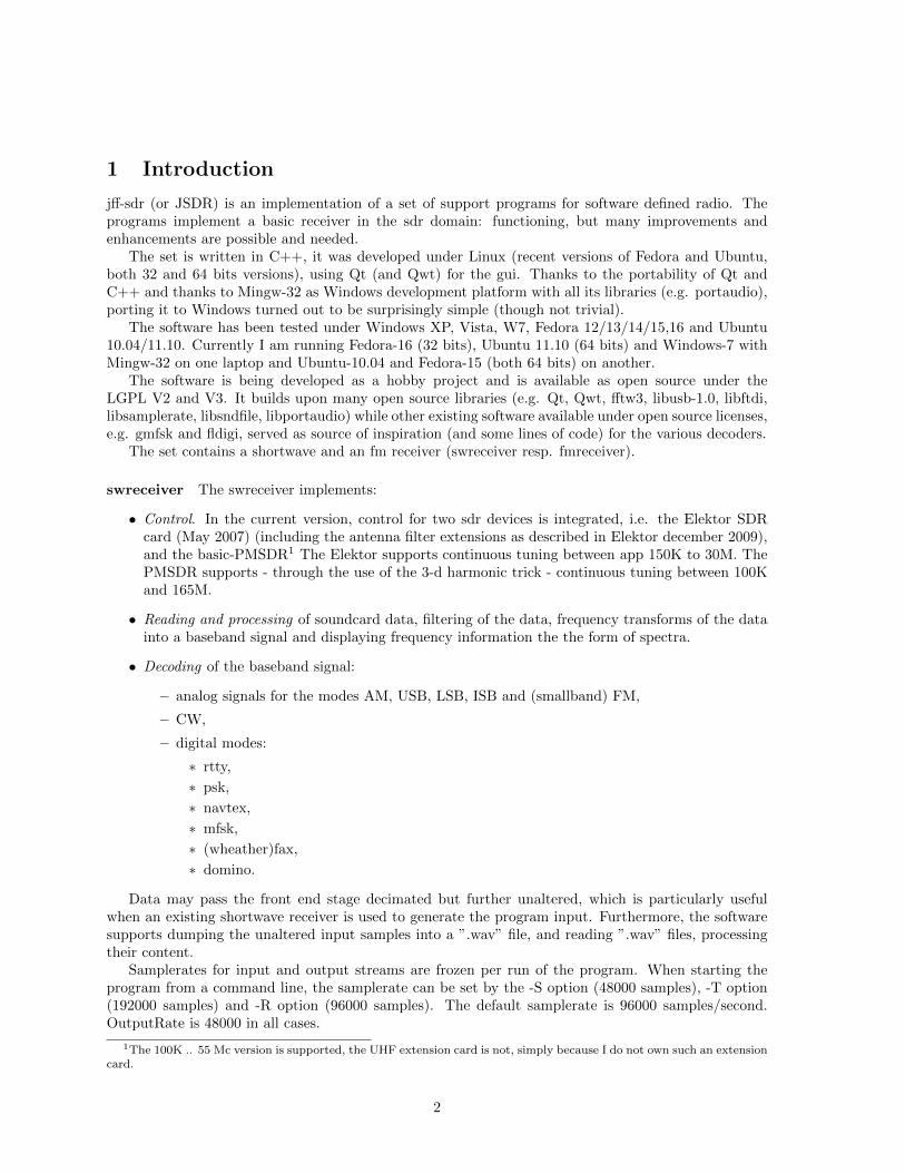
4.7 Setting AGC
For AM reception, AGC might be useful. The implementation of AGC within this software is still inits infancy, however, functioning. Selecting the AGC (either AGC off, AGC slow or AGC fast) is bythe appropriate combo-box.
12
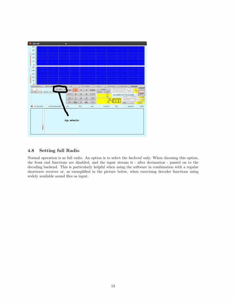
4.8 Setting full Radio
Normal operation is as full radio. An option is to select the backend only. When choosing this option,the front end functions are disabled, and the input stream is - after decimation - passed on to thedecoding backend. This is particularly helpful when using the software in combination with a regularshortwave receiver or, as exemplified in the picture below, when exercising decoder functions usingwidely available sound files as input.
13
4.9 Dumping the inputstream
In order to allow repetition of experiments, a simple mechanism for dumping the inputstream is im-plemented. Pushing the dumpON button will invoke a fileselector and once a file(name) is chosen (orgiven), the inputstream will be written - unaltered - to this file. The format with which the datais written is the regular ”.wav” format, the baudrate is the baudrate the receiver is operating upon.Pushing the dumpOFF button causes the file to close and turn the mechanism off. Note that in thecurrent version there is no indication when the data is dumped.
14

The resulting ”.wav” file can be used as input through the ”file input” mechanism of the receiver.
4.10 Selecting a decoder
Front end processing transforms the signal into a baseband signal with a bandwidth as specified in theworkingrate selector (the selector to the left of the value display showing the samplerate). The signalis filtered to the bandwidth specified and can be decoded.
The default decoder is the ”no-decoder”, this (non-)decoder will just transform the incoming data up
15

to the samplerate needed for the output card, while displaying the decoder input in two dimensions(i.e. the I and the Q) on a small screen.
A decoder can be selected by clicking the requested decoder (radio) button.
5 Handling decoders
5.1 Analog decoder
In the mode ”analog decoder”, the following analog decoding modes are available:
• usb;
• am;
• lsb;
• smallband fm;
• isb, double side band detection;
• synchronous am decoder.
Notice that selecting an analog decoding mode such as lsb, does not change the setting of thepassband. Filtering is such that when choosing the lsb decoding mode while having selected the usbpassband, hardly any signal will be heard.
The sliders speak for themselves. It must be noted that the squelch is automatically invoked in thefm decoding mode.
16
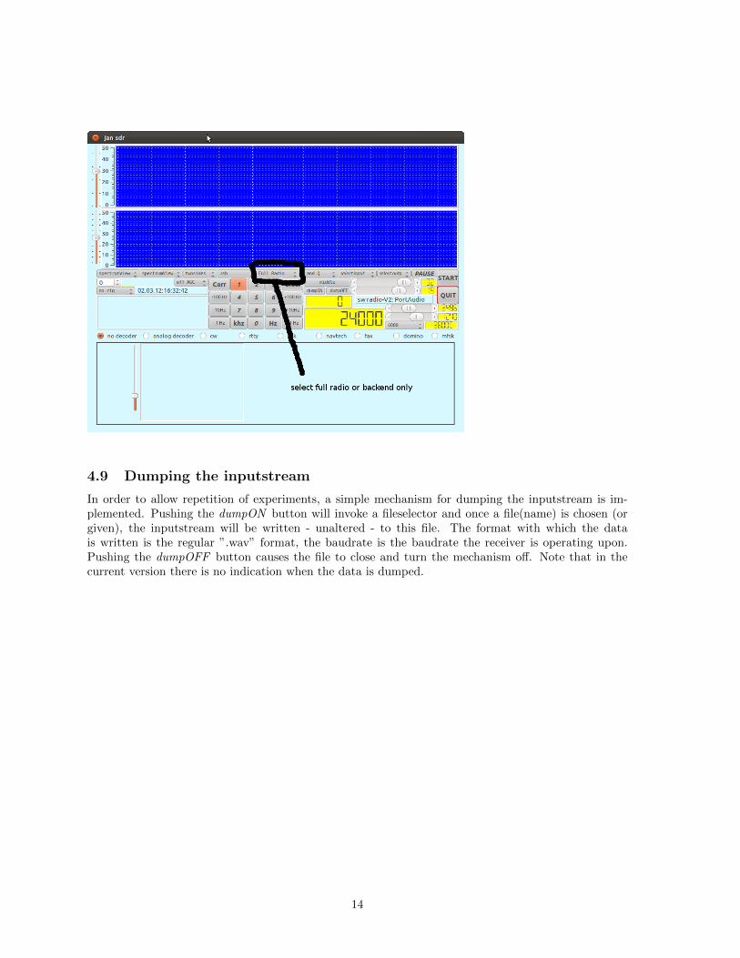
5.2 Cw decoder
The cw decoder decoder will attempt to guess the speed, however, up to a limit specified by theuser. Setting an upper limit to this speed is with the selector left to the ”words per minute” display.Sometimes it is beneficial to increase this value, its default value is 32.
Notice that the working IF for this decoder is chosen to be 800 Hz, tuning to a station that sendson frequency X then requires setting the receiving frequency on X - 800.
The squelch is used to set a threshold in the signal, below which it is considered noise.The filterdegree can be set, it is default set to 12, which is a reasonable value for the type of filter
(Butterworth).The four boxes displaying values:
• the top two indicated the estimated length of the dot and the space.
• the bottom two indicate (clamped) levels for the peak of the signal and the estimated noise level.These value displays are merely for debugging purposes.
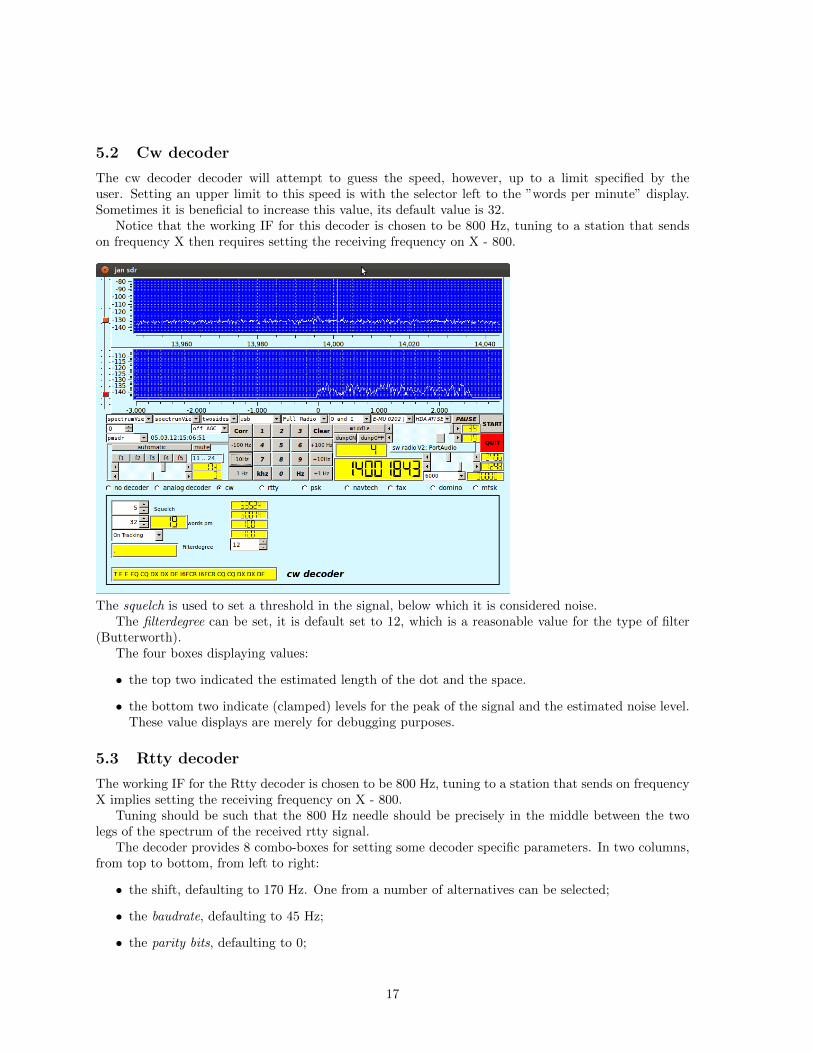
5.3 Rtty decoder
The working IF for the Rtty decoder is chosen to be 800 Hz, tuning to a station that sends on frequencyX implies setting the receiving frequency on X - 800.
Tuning should be such that the 800 Hz needle should be precisely in the middle between the twolegs of the spectrum of the received rtty signal.
The decoder provides 8 combo-boxes for setting some decoder specific parameters. In two columns,from top to bottom, from left to right:
• the shift, defaulting to 170 Hz. One from a number of alternatives can be selected;
• the baudrate, defaulting to 45 Hz;
• the parity bits, defaulting to 0;
17

• the MSB, i.e. Most Significant Bit first or last;
• the afc, defaulting to off;
• the interpretation mode: normal or reverse, defaulting to normal;
• the wordlength in bits, defaulting for rtty to 5;
• the number of stopbits, defaulting to 1.
The four value displays indicate:
• the actual IF, when the afc is on one might look at the changes in this value and use that as anaid in tuning;
• a very rough estimate of the frequency error, not a very useful figure, is being used to test somealgorithms;
• the estimated baudrate;
• the estimated shift.
5.4 Psk decoder
The IF for the psk decoder is chosen to be 800 Hz. This means that for selecting a station at frequencyX, the receiver should be tuned to X - 800.
Characteristic for the psk decoder is the dial display at the left size of the decoder specific subscreen.While operating, this display will show the phase angle between - perceived - subsequent psk bits. Ideallythe values shown are 0 and 180 degrees.
The parameters to be controlled are:
• the afc, allowing the software to change the IF somewhat in order to improve reception;
• normal or reverse interpretation of the incoming signal;
18

• the psk or bpsk mode;
• the threshold used to distinguish noise from signal. The scale used has no specific physical meaning.
• the strength of the filter used to separate the signal on the IF from other signals in the environment.The degree indicates the order of the Butterworth filter being used.
The two value displays indicate the actual IF and the signal quality respectively.
5.5 Fax decoder
For the fax decoder we have chosen an IF to be 0 Hz, the selected frequency is therefore the frequencyin the middle of the fax signal. Fax signals are well bounded by a 1000 Hz filter, the presets for thebandfilter therecore contain a 1000 Hz specification. The fax decoder has a lot of parameters that canbe set:
• the top row contains spin-boxes for
– the start frequency for a fax recording, default 300 Hz;
– the stop frequency for a fax recording, default 450 Hz;
– the IF, default 0;
– the deviation in Hz, default 400 Hz;
– the LPM (lines per Minute), default 120.
• the second row has two value displays, a combo-box and a textlabel:
– the Linenumber of the current fax;
– the current APT frequency;
– the selector for Black and White, Gray or Colour;
19

– the label stating the current step selection;
• the third row contains 4 combo-boxes:
– the IOC (Index of Cooperation) Selector, default 288 for wheatherfaxes;
– the phase selector, selecting whether or not the phase is inverted;
– the modulation mode selector, either FM or Am, defaulting to FM;
– the skip button, allowing the current processing step to move on to the next one.
• the fourth row contains two combo-boxes:
– the save button, defaulting to no save. If save is selected, a filename will be asked for andthe fax will be saved upon reaching the end;
– the demodulator selector. Three different demodulators are implemented (just to experi-ment), this combo-box alles selecting one.
5.6 Mfsk decoder
As with the other decoders, the IF for the domino decoder is chosen to be 800Hz. This means that forselecting a station at frequency X, the receiver should be tuned to X -800.
Tuning to an mfsk transmission is quite hard, therefore the decoder screen contains two additionaldisplays that may help. The top display, indicated as Tuning indicator contains three elements, twored fields with a green field in the middle. The red field at the left indicates that the maximum of thepresumed signal is too low a frequency to fit, the red field at the right the same for too high a frequency.In the picture below, the tuning indicator indicates correct tuning.
Below this tuning indicator, a small waterfall display shows the tones of signal in more detail. Itshows 10 more tones than the mfsk signal is supposed to have such that it might help in correctly tuningthe signal.
The decoder provides 3 combo-boxes for setting parameter values:
20

• the afc, by default off;
• whether the incoming signal is to be interpreted normal or reversed w.r.t the base tone;
• the mfsk mode.
Furthermore, the decoder has a box with which a threshold value can be set, below which incomingsignal is to be considered noise.
The slider on the screen can be used to set the IF, for normal operation it is hardly useful. It isreminiscent of some previous experiments.
The three value displays on the screen show:
• the - perceived - quality of the signal;
• the estimated baudrate;
• the IF, which only changes when the afc is set.
Notice that, since in the period of writing no real mfsk transmission was caught, the screen for thismode was made while processing a file with the backend option of the software.
5.7 Navtex decoder
Navtex decoding uses an IF of 800 Hz, so the tuned frequency should be 800 Hz less than the sendingfrequency. The parameters, settable though combo-boxes, are:
• afc, default off;
• normal or reverse interpretation of the incoming signal;
• strict FEC or non-strict FEC.
• message or general text. In case ”message” is chosen, the messages displayed are the propernavtech messages enclosed between ”ZCZC” and ”NNNN” sequences.
21

The value displays indicate:
• the actual IF (will only change obviously when afc is set);
• the strength of the signal.
5.8 Domino decoder
As with the other decoders, the IF for the domino decoder is chosen to be 800Hz. This means that forselecting a station at frequency X, the radio should be tuned to X -800.Domino is by itself an easy mode, tuning is - within limits - not very critical. The various combo-boxes(from top to bottom):
• selecting the domino mode and speed;
• normal or reverse interpretation;
• with or without FEC;
• setting a squelch-level for the decoding.
22
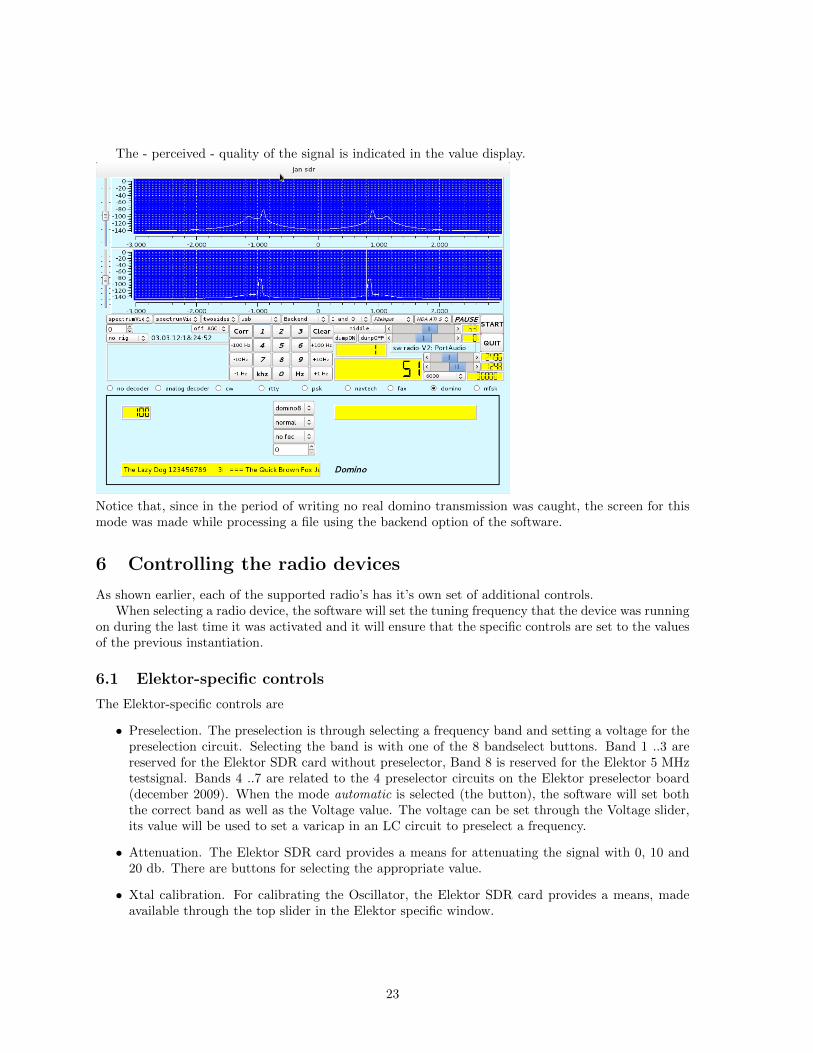
The - perceived - quality of the signal is indicated in the value display.
Notice that, since in the period of writing no real domino transmission was caught, the screen for thismode was made while processing a file using the backend option of the software.
6 Controlling the radio devices
As shown earlier, each of the supported radio’s has it’s own set of additional controls.When selecting a radio device, the software will set the tuning frequency that the device was running
on during the last time it was activated and it will ensure that the specific controls are set to the valuesof the previous instantiation.
6.1 Elektor-specific controls
The Elektor-specific controls are
• Preselection. The preselection is through selecting a frequency band and setting a voltage for thepreselection circuit. Selecting the band is with one of the 8 bandselect buttons. Band 1 ..3 arereserved for the Elektor SDR card without preselector, Band 8 is reserved for the Elektor 5 MHztestsignal. Bands 4 ..7 are related to the 4 preselector circuits on the Elektor preselector board(december 2009). When the mode automatic is selected (the button), the software will set boththe correct band as well as the Voltage value. The voltage can be set through the Voltage slider,its value will be used to set a varicap in an LC circuit to preselect a frequency.
• Attenuation. The Elektor SDR card provides a means for attenuating the signal with 0, 10 and20 db. There are buttons for selecting the appropriate value.
• Xtal calibration. For calibrating the Oscillator, the Elektor SDR card provides a means, madeavailable through the top slider in the Elektor specific window.
23

6.2 PMSDR-specific controls
The PMSDR-specific controls are
• Mute selector. The hardware supports muting, selectable by the mute button.
• The filter selection. Filters can be selected automatically or manually. In case of a manualselection, the filter f1 .. f4 select predefined filters, f5 selects no filter.
• The bottom slider is the bias slider, setting the bias for the PMSDR kit;
• the next slider is the gain slider, which is - unfortunately - not implemented in the recent versionsof the firmware of the PMSDR.
24
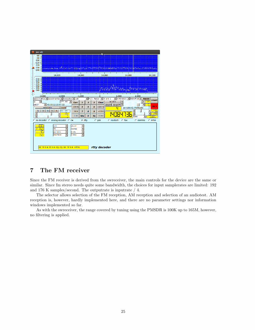
7 The FM receiver
Since the FM receiver is derived from the swreceiver, the main controls for the device are the same orsimilar. Since fm stereo needs quite some bandwidth, the choices for input samplerates are limited: 192and 176 K samples/second. The outputrate is inputrate / 4.
The selector allows selection of the FM reception, AM reception and selection of an audiotest. AMreception is, however, hardly implemented here, and there are no parameter settings nor informationwindows implemented so far.
As with the swreceiver, the range covered by tuning using the PMSDR is 100K up to 165M, however,no filtering is applied.
25

In the above picture, the receiver is processing pre-recorded data in FM Mode. The second displayshows the demodulated FM signal, clearly visible are the pilot tone at 19 Khz and the rds signal at 57Khz.
Below the device selector a selector for the NTI downconverter is placed. This downconvertersubtracts 80 Mhz from the received signal.
The subscreen on the bottom of the screen contains the specific controls and displays for the FMreception. The top line contains:
• a combo box for the selection of the fm demodulator. Currently 5 different (or at least differentfrom a coding perspective) are implemented.
• a label field indicating the name of the selected demodulator,
• the stereo/mono selector,
• the selector for the output channels. In particular interesting is the field L-R here since the qualityof the L-R signal largely determines the quality of the stereo reception.
• the view selector, with which one can select what will be made visible in the second large display.It was used for debugging purposes and kept. Selecting view 8, while having selected rds, showsthe rds signals.
• the deemphasis selector, allowing a choice between us and european standards.
• Lowpass filter selector.
• field indicating the ratio of erroneously received bits in the rds stream.
26

The second line contains:
• the rds selector. One can choose between no rds, rds1 and rds2, the latter with the same function-ality, but different implementation techniques. rds1 is inspired by cuteSDR and is using matchedfilters to improve isolation of the pure rds signal, rds2 is mainly a recoding of parts of FMstacksoftware,
• the field indicating whether or not rds is ”in sync” or not,
• the music/speech flag as given by the rds stream,
• the field indicating a usable pilot signal,
• a balance slider between the left and right output channel and a balance indicator,
• the number of CRC errors in decoding the rds stream,
• the PI code as received by the rds stream.
The third line contains two text fields, filled with texts as decoded from the rds stream, an indicationof the number of synchronization errors and a field indicating alternative frequencies for the stationbeing received.
8 Building an executable
Building an executable for either the fmreceiver or the swreceiver is - unfortunately - not (yet) throughthe simple ”configure/make” sequence with the Gnu autotools. The distribution relies on the qmaketool, a tool in the Qt suite, provided with Qt for generating a makefile, including the required MOCcompilation.
The distribution contains four programs. The directory docs contains this document, the directorydemo contains a simple filter demonstration program, and the directory sound contains sources for asimple sound generator. The directory swreceiver contains the main sources for the sw receiver, thedirectory fmreceiver contains the main source needed for the fm receiver. Other directories containsupport files.
27

8.1 Building under Ubuntu/Fedora
In Ubuntu and Fedora one need to have packages installed for
• qt4. When also installing qt-4 designer one can easily adapt the GUI, and installing qt4-designercauses all relevant qt4 packages to be installed as well.
• libqwt5-qt4 and the accompanying files in the development package libqwt5-qt4-dev. Notice thatqwt-6 has some changes that prohibit some files to compile, so ensure that qwt-5.2 is installed.
• libfftw3 and the development package libfftw3-dev.
• libportaudio2 and the development package portaudio19-dev.
• libftdi1 and the development package libftdi-dev.
• libusb-1.0 and the development package libusb-1.0-dev.
• libsndfile1 and the development package libsndfile1-dev.
• libsamplerate0 and the development package libsamplerate0-dev.
The good news is that all of these packages are available on the various repositories for Ubuntu andFedora.
Please have a look at the file ”swreceiver.pro”, resp. ”fmreceiver.pro”, these files are being processedby qmake to generate a makefile.
A handy script for creating the right environment on a Fedora-16 machine was given by FrancescoMarzani:
sudo apt-get install gcc gcc-c++ \
qt qt-devel qt qwt qwt-devel \
fftw fftw-devel \
alsa-lib alsa-lib-devel alsa-tools portaudio portaudio-devel \
libsndfile libsndfile-devel libsamplerate libsamplerate-devel alsa-plugins-samplerate \
libusb1 libusb1-devel libftdi libftdi-devel
#prerequisites install check
echo "
uname -a
echo " "
rpm -qa | grep "gcc"
echo " "
rpm -qa | grep "qt"
echo " "
rpm -qa | grep "qwt"
echo " "
rpm -qa | grep "fftw"
echo " "
rpm -qa | grep "alsa"
echo " "
rpm -qa | grep "portaudio"
echo " "
# modify swreceiver.pro ( from Ubuntu to Fedora - uncomment/comment )
# qmake-qt4 Fedora , qmake Ubuntu
# audio/pulse group check
28

sudo more /etc/group | grep "audio"
sudo more /etc/group | grep "pulse"
sudo more /etc/group | grep "pmsdrusb"
sudo more /etc/group | grep "($USER)"
id $USER
echo " "
#check audio
arecord -l
aplay -l
aplay -v ring.wav
echo " "
modprobe snd-aloop
aplay -l
echo "
There are slight differences in the places where Ubuntu resp. Fedora keep some of the include filesas well as in the naming of some of the libraries to be included. Each of the ”.pro” files contains twospecifications, one for ubuntu and one for fedora. Each specification is of the form
unix {....}.
with a text comment line telling which Linux is meant. Commenting one specification out is by precedingthe lines with a sharp-sign (#).
Once the ”.pro” file is set for either ubuntu or fedora, one should only have to run
qmake (qmake-qt4 for fedora)
make
after which the program, swreceiver or fmreceiver, is built.Please note that for actually running the program with a receiver connected to the USB gate, one
needs to have sufficient privileges. My personal script is a ”sudo ...” one.
8.2 Building under Windows
Using the MINGW toolkit, together with the open source distribution of Qt, it is possible to build thesoftware under Windows. It was done successfully under XP, Vista and W7. The major advantageis that under windows the ASIO interface software can be used for the EMU-202 I am using. TheWindows software for this device supports samplerates up to 192KHz, which is required for a decentdecoding of stereo FM signals, together with RDS signals. Currently, support for the Emu under Linuxprovides samplerates up to 96000. For me, FM under Linux is only possible with prerecorded files.
The disadvantage is that building the software under windows is somewhat more complicated thanbuilding it under Linux. Most likely it is also possible using the Microsoft compilers and toolkit, butmy experience is limited to Mingw.
In order to build:
1. Have Mingw installed, a simple tool ”mingw-get” exists with which a complete mingw/msysenvironment can be downloaded;
2. Download and install the open source version of Qt and fill in the existing paths for Mingw whenasked for. There is some mumbling on incorrect versions but that follows from Qt expecting anolder version of Mingw;
3. Add Qt and Mingw to the Path (in my case:
29

QTDIR=c:\Qt\4.7.4
MINGW=c:\mingw\
%QTDIR%\bin en %MINGW%\bin
)
4. download and install fftw3, there is a installable version for Mingw. There is no need to recompile,although it is possible.
5. download and install Qwt-5.2.2. Notice that the receiver software is not yet prepared for Qwt-6;
6. download and install libsndfile and libsamplerate;
7. download a reasonable recent version of the sources for portaudio. Furthermore, for the use ofASIO, the ASIOSDK2 should be downloaded as well. Configuring portaudio for both ASIO andthe default MME soundinterface:
./configure --with-winapi=wmme,asio --with-asiodir=../ASIOSDK2
make
make install
did the trick. To complicate matters, the sources for this version of Portaudio had to be adaptedslightly, see the internet for details. I was told that that problem is addressed by the PA people.Once it is working, it works great.
8. libftdi and libusb-1.0 are easily installed using the development kit e.g. libftdi1 devkit MINGW32 XXXX,with XXXX standing for the construction date. Be aware that libusb-1.0 is not libusb-0.1. Followthe installation instructions, including adapting the specific drivers.
9. When all includes, libraries and DLL’s are in the right place, life is (finally) easy:
qmake -r config+=RELEASE
make -f Makefile.Release
./release/swreceiver
will do the trick.
Although quite some work, it works great!!
9 Sources of inspiration
The software uses many ideas - and in some cases lines of code - from others. The main sources ofinspiration for various parts - other than Qt or Mingw - are
• Signals, Samples and Stuff: A DSP Tutorial by Doug Smits (QEX 1998, 4 parts), really the setof papers that made me decide to do some programming in the field of SDR.
• The Scientist and Engineer’s Guide to Digital Signal Processing By Steven W. Smith, Ph.D.California Technical Publishing P.O. Box 502407 San Diego, CA 92150-2407. This book, foundon the internet, provided me with a first introduction to digital processing. All 640 pages areavailable on the internet.
• Practical Analog and Digital Filter Design by Les Thede, Artech House, which provided me withthe basics for IIR filters, their design and their implementation.
30

• Implementation of FM Demodulator Algorithms on a High Performance Digital Signal Proces-sor by Franz Schnyder, Christoph Haller. Diploma Thesis Hochschule fur Technik Rapperswil,Nanyang technological University 2002. Gave a readable overview on 4 (5) different algorithmsfor the decoding of FM.
• CuteSDR Technical Manual, October 2011 by Moe Wheatly, which gives a good view on varioustechniques used in the cuteSDR software and helped to improve some of the algorithms used.
• sources of many existing programs, in particular
– RTTY, an FSK decoder program for Linux (Jesus Arias, 2001). This program gave the firsthints to process CW and RTTY.
– fldigi (W1HKJ), that gave the hint on how to handle CW with an adaptive algorithm.
– gmfsk (Tomi Manninen OH2BNS). A great program that gave insight in decoding the psk,mfsk and domino.
– hamfax (Gerhard Schmitt), which was the source for the fax implementation.
– digiRadio (Alberti Perotti and others), and
– FM Stack (Michael Feilen), that gave the inspiration for the FM software.
– The pmsdr interface software (Martin Pernter, Andrea Montefusco), and the Si570 datasheets,
– The elektor interface software (Burkhard Kainka) and the hamlib software that learned mehow to handle the Elektor card.
• and numerous anonymous sources on the internet.
10 Availability and licensing
This software is available under the GPL. It was written by me, updated by me, using many ideas -and even lines of code - from others, as far as I can trace all available under the GPL.
/*
*
* Copyright (C) 2010, 2011, 2012
* Jan van Katwijk ([email protected])
* JFF Consultancy
*
* This file is part of the JSDR (ESDR).
* Many of the ideas as implemented in this software are derived from
* other work, made available through the GNU general Public License.
* All copyrights of the original authors are recognized.
*
* JSDR is free software; you can redistribute it and/or modify
* it under the terms of the GNU General Public License as published by
* the Free Software Foundation; either version 2 of the License, or
* (at your option) any later version.
*
* JSDR is distributed in the hope that it will be useful,
* but WITHOUT ANY WARRANTY; without even the implied warranty of
* MERCHANTABILITY or FITNESS FOR A PARTICULAR PURPOSE. See the
* GNU General Public License for more details.
31
*
* You should have received a copy of the GNU General Public License
* along with ESDR; if not, write to the Free Software
* Foundation, Inc., 59 Temple Place, Suite 330, Boston, MA 02111-1307 USA
*
*/
32