the isolated electron - national institute of - tf.nist.gov · pdf filethe isolated electron...
TRANSCRIPT

The Isolated Electron From a single electron trapped in an artificial atom of macroscopic size a property of the electron called the g factor can be measured with unexcelled accuracy
by Philip Ekstrom and David Wineland
he electron is a remarkably sim- ple particle of matter. It has mass T and an electric charge; it spins (or
seems to spin) with a b e d amount of angular momentum, and it has a mag- netic moment, so that an external mag- netic field exerts a twisting force on it. These four quantities constitute all the known properties of the electron; once their values have been established there is nothing more to be said about the electron.
It can be argued that the electron is even simpler than this tabulation of properties might suggest. The reason is that the four quantities are not all inde- pendent; instead any one of them can be derived from the other three. For exam- ple, the magnetic moment of the elec- tron is related to its mass, charge and spin by a constant of proportionality called the g factor. In the modern theory of electrons the value of the g factor can be calculated with great precision, and it can also be measured experimentally. Such measurements are therefore a sen- sitive test of the theory. Both the calcu- lation and the measurement are difficult, but they have been refined to such an extent that the g factor of the electron is now known to greater accuracy than any other physical constant. The values derived from theory and from experi- ment are in accord to the last decimal place known.
A series of experiments that has been under way for some years at the Univer- sity of Washington has recently culmi- nated in a new measurement of the g factor, which has set a new record for accuracy. The experiments employed a
novel technique in which a single elec- tron is confined for weeks at a time in a “trap” formed out of electric and mag- netic fields. In effect the electron and the confining apparatus make up an atom with macroscopic dimensions and an ex- traordinarily massive nucleus. Because the apparatus rests ultimately on the earth the nucleus might even be identi- fied with the earth itself, and so the arti- ficial atom has been given the name geo- nium, the earth atom. The motion of the single electron in geonium is different from that in an ordinary atom, and it is more accessible to manipulation and measurement. For these reasons it was possible to measure the g factor with an uncertainty of less than one part in 10 billion.
hen the electron was discovered in W 1897 by J. J. Thomson, it was im- mediately obvious that the particle has mass and electric charge; indeed, Thom- son made his discovery by measuring the ratio of mass to charge. It was also assumed, at least implicitly, that the electron has the familiar mechanical properties characteristic of all bulk mat- ter, such as a definite size and shape. A magnetic moment and an intrinsic quan- tity of spin angular momentum were added to the list of properties some years later during the development of the quantum theory, following a pro- posal made by Samuel A. Goudsmit and George E. Uhlenbeck. The spin and magnetic moment were required in or- der to explain certain features observed in the spectrum of light emitted or ab- sorbed by atoms.
TRAP FOR AN ELECTRON captures the particle in a special configuration of electric and magnetic fields The electron occupies the central cavity formed by the two cap electrodes and the ring electrode, which are machined to a mathematically determined shape: they are hyper- boloids Two additional electrodes, the guard rings, compensate for imperfections in the elec- tric field. The entire apparatus, which is about an inch and a half in diameter, is immersed in liquid helium and inserted into the core of a superconducting magnet The electron is bound by the combination of static electric and magnetic fields in the trap, much as an electron in an atom is bound to the nucleus. Here the part of the nucleus is played by the apparatus, or even by the earth, on which the apparatus rests, and so the atom is called geonium, the earth atom.
With these properties it might seem that the electron could be understood in terms of a simple mechanical mod- el. The electron could be imagined as a material particle with some definite size and shape and with a negative electric charge distributed over its surface. The particle would be required to spin about an axis, much as the earth does, with a specified and unvarying quantity of an- gular momentum.
In this model the magnetic moment of the electron has a straightforward expla- nation. The rotation of a body with a charge on its surface necessarily entails a circulation of electric charge, or in other words an electric current. The cir- culating current gives rise to a magnet- ic field in the electron just as it does in the windings of an electromagnet. Both the spin angular momentum and the magnetic moment can be represented by vectors, or arrows, lined up along the spin axis. By convention (and because the charge of the electron is negative) the vectors representing the spin and the magnetic moment point in opposite directions.
Continuing to reason in terms of this mechanical model, one would expect the magnetic moment to be proportion- al to the electric current circulating at the perimeter of the spinning electron. The current should be directly propor- tional to the total electric charge and to the rotational velocity. The rotation- al velocity in turn should be directly proportional to the spin angular mo- mentum and inversely proportional to the mass of the electron. The relation among these quantities, along with some numerical factors needed to keep the system of units consistent, can be ex- pressed succinctly in an equation:
e p=-gqamc S.
Here p (the Greek letter mu) is the mag- netic moment of the electron, s is thz spin angular momentum, e is the charge, m is the mass and cis the speed of light in a vacuum. The constant of proportion- ality in the equation is the g factor, a
105

h
VECTOR OF SPIN ANGULAR MOMENTUM (s)
CHARGE (e) VECTOR OF MAGNETIC
MOMENT (p)
I 11 PROPERTIES OF THE ELECTRON are electric cbarge (e), mass (mh spin angular momen- tum (s) and magnetic moment (p). A naive mecbnicd model conceives of the electron as a spinning disk witb electric cbarge distributed on its perimeter. It is tbe current of circulating charge tbat gives rise to the magnetic moment, and the moment can therefore be derived from tbe otber tbree properties. "be relation is defined by an equation in wMcb a constant of propor- tionality called tbe g factor appears, Tbe minus sign in tbe equation signifies tbpt tbe moment is opposite to tbe spin vector. The modern tbeory of electrons does not d o w sucb a pictorial representation, but tbe relation of tbe magnetic moment to the spin still bolds, and g can be CPE culpted with great precision. In tbe geonium experiments g is measured witb equal precision.
dimensionless number. The g factor de- termines how large a magnetic moment will be generated by a given amount of spin, charge and mass. The minus sign that precedes the g factor signifies that the magnetic moment is antiparallel to the spin angular momentum.
In this mechanical model the value assigned to g depends critically on the shape and size of the electron and on how the electric charge is distributed over its surface. The first experimental values of g came from the same spec- troscopic observations that suggested the existence of an intrinsic spin angu- lar momentum. Those observations indi- cated that g is approximately equal to 2. Some years later a more refined version of the quantum theory, formulated by P. A. M. Dirac to be consistent with the special theory of relativity, made pos- sible a precise theoretical calculation of 8; the value predicted was exactly 2, in agreement with the observational evi- dence available at the time.
iewing the electron as a rigid, rotat- V ing body is somewhat naive; after all, the motion of the particle must be described by the laws of quantum me- chanics, where the notions of size and velocity cannot even be defined beyond a certain level of precision. Indeed, the model has grave flaws, some of which were recognized only days after it was first proposed. For example, it turns out that the rotational velocity at the sur- face of the electron is greater than the speed of light. Another source of diffi-
.culty is the size attributed to the elec- tron. The mass or energy of an electri- cally charged particle depends inversely on its size. One reason this is so can be understood by noting that energy is required in order to pack the repulsive
negative charge of the electron into a finite volume. The smaller the volume, the larger the energy needed. Accord- ing to this scheme, the quite small mass or energy of the electron implies that it should have a rather large size. Experi- ments in which electrons are scattered by other particles, however, effective- ly measure the sue of the electron, and they indicate that the radius must be ex- ceedingly small. Indeed, all experimen- tal data gathered so far are consistent with the idea that the electron is a point particle, entirely without extension. The arguments presented here then predict that the electron mass is infinite, a mani- fest absurdity.
Still another reason for doubting the accuracy of the mechanical model, and that of the Dirac theory as well, derives from refined measurements of the g fac- tor of the electron. Experimental evi- dence has shown that g is not exactly 2 but rather is greater than 2 by about . I percent; in other words, its value is roughly 2.002. The Dirac theory could not accommodate such an adjustment.
In the 1940's these problems were re- solved by abandoning the mechanical model of the electron and devising a new and more abstract theory, quan- tum electrodynamics. In quantum elec- trodynamics the electron is allowed to be a dimensionless point particle and its mass is allowed to be infinite, at least in principle. Surprisingly, there is a mathemJtica1 procedure (called renor- malization) that cancels this infinity and recovers the observed, finite properties of the electron, including the g factor.
It is far from obvious how a particle with zero radius can have spin angular momentum or a magnetic moment. If quantum electrodynamics offers no con- sistent mental picture, however, it does
- -
provide an explicit procedure for calcu- lating the numerical values of the vari- ous properties of the electron. The re- lation between the electron's magnetic moment and its spin, charge and mass takes the same form it had in the me- chanical model, and the constant of pro- portionality in the equation is the sameg factor. Moreover, a first approximation still yields a value of g = 2. That is only an approximation, however, and an infinite series of progressively small- er corrections can be applied to it. Find- ing the exact value of g by this method is impractical because the entire series of terms would have to be included in the calculation, but any finite precision can be attained by evaluating a finite number of terms.
eginning in 1950, a series of experi- B mental measurements of the g fac- tor was undertaken by H. R. Crane and a number of his colleagues and students at the University of Michigan. What was actually measured was not g but the discrepancy between g and 2, and so the project came to be known as the g-minus-2 experiment. Over the next two decades a succession of increasingly precise values was reported by Crane, Arthur Rich and their collaborators [see "The g Factor of the Electron," by H. R. Crane; SCIENTIFIC AMERICAN, January, 19681. During the same period theorists worked to evaluate progressively more complex terms in the infinite series. The ensuing duel between theory and exper- iment was punctuated by a few errors and subsequent corrections, but by 1972 the calculated and measured values of g agreed to better than eight significant figures. An incidental benefit of this competition was the development of new methods both for theoretical calcu- lations and for experiments. It seemed that each additional decimal place de- manded some technical innovation.
In the Michigan experiments a beam of electrons was passed through a mag- netic field in an apparatus where the ori- entation of the electrons' spin axis (or magnetic moment) could be determined both before the passage and after. The applied field had two effects on the elec- trons: it caused their spin axes to precess and it caused the electrons themselves to describe a circular or helical orbit. If g were exactly 2, the frequency of the spin precession and the orbit frequency would be equal. The experiment mea- sured the difference between the fre- quencies and hence determined g - 2.
The accuracy of this method is limit- ed mainly by the statistical nature of an experiment done with many interacting electrons and by deficiencies in the ex- perimenter's knowledge of what hap- pens to an electron during the mea- surement. Each electron moves through the apparatus at high speed and spends much less than a second in the magnetic field. During that interval its trajectory
i
i
!
I ,
I
I
I I
I
t
I
j I
i
1
can be ajtered by inhomogeneities in the field and by encounters with other elec- trons in the beam. The Michigan group continues to improve the experiment, seeking to control these uncertainties.
An alternative strategy for improving the measurement of g is to confine a single, slow-moving electron for an ex- tended period in an environment that is simple enough to be analyzed precisely. This is the plan adopted in the geonium experiments done at the University of Washington. Th_e goal of these measure- ments-a goal that can be approached but never attained-is to isolate an elec- tron from all extraneous influences and make it hold still for examination. The long-term confinement of free electrons was conceived more than 20 years ago by Hans G. Dehmelt of Washington, and the work described here was carried out under his direction. The techniques for preparing and observing an isolated electron were developed mainly by us, although our work was founded on ex- periments with trapped clouds of elec- trons done by our predecessors, Fred L. Walls and Talbert S. Stein. We have since left the project, but the single-elec- tron techniques have been refined fur- ther by Robert S. Van Dyck, Jr., and Paul B. Schwinberg, who have mea- sured the g factor with great accuracy.
o understand the behavior of the T electron in the geonium atom it is helpful first to consider a simpler, ideal- ized system: an electron at rest in a uni- form magnetic field. Such a field can be represented by flux lines that are all par- allel and evenly spaced. The energy of this stationary electron depends on the orientation of its magnetic moment with respect to the external field. The energy is minimum when the moment and the field are parallel and maximum when they are antiparallel.
It turns out that these two orientations of the electron, which are commonly called “spin down” and “spin up,” are the only ones possible. All intermediate orientations, where the magnetic mo- ment would be perpendicular to the field or would cross it obliquely, are forbid- den by the rules of quantum mechanics. (To be precise, the rules apply to the orientation of the spin axis and only in- directly to the magnetic moment. Since the two vectors always point in precise- ly opposite directions, however, the ori- entation of the electron can be defined with reference to either one of them.)
Because an electron has only two pos- sible orientations a stationary electron in a uniform magnetic field has just two distinct energy levels. The difference in energy between the levels is the product of three quantities. One of these quan- tities is a combination of fundamen- tal constants called the Bohr magneton, which defines the coupling between an applied magnetic field and the magnetic moment of a particle. The Bohr magne-
CYCLOTRON MAGNETIC FORCE RESULTANT FORCE
RON UNIFORM MAGNETIC FIELD MOMENTUM
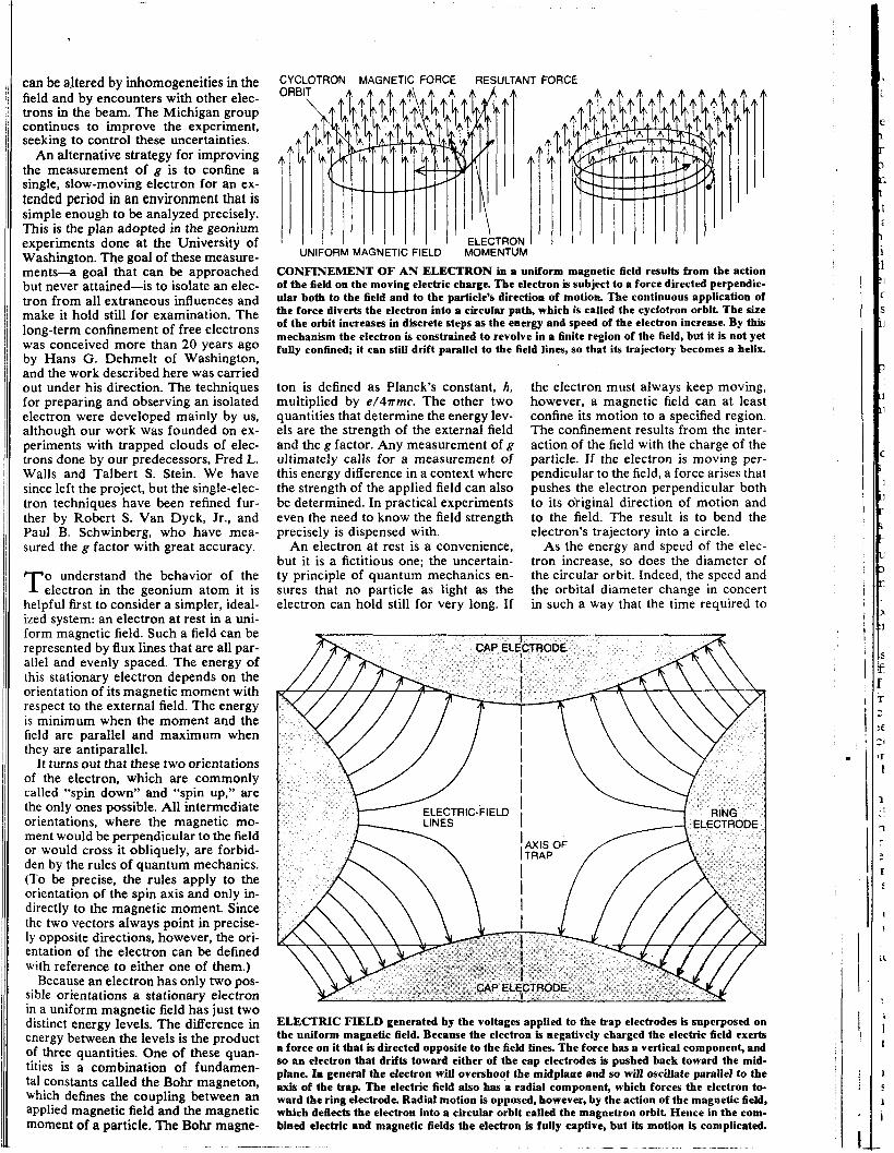
CONFINEMENT OF AN ELECTRON in a uniform magnetic field results from the action of the field on the moving electric charge. The electron is subject to a force directed perpendic- ular both to the field and to the particle’s direction of motion. The continuous application of the force diverts the electron into a circular path, which is called the cyclotron orbit The size of the orbit increases in discrete steps as the energy and speed of the electron increase. By this mechanism the electron is constrained to revolve in a finite region of the field, but it is not yet fully confined; it can still drift parallel to the field lines, so that its trajectory becomes a helix.
ton is defined as Planck’s constant, h, multiplied by e / 4 ~ m c . The other two quantities that determine the energy lev- els are the strength of the external field and the g factor. Any measurement of g ultimately calls for a measurement of this energy difference in a context where the strength of the applied field can also be determined. In practical experiments even the need to know the field strength precisely is dispensed with.
An electron at rest is a convenience, but it is a fictitious one; the uncertain- ty principle of quantum mechanics en- sures that no particle as light as the electron can hold still for very long. If
the electron must always keep moving, however, a magnetic field can at least confine its motion to a specified region. The confinement results from the inter- action of the field with the charge of the particle. If the electron is moving per- pendicular to the field, a force arises that pushes the electron perpendicular both to its ofiginal direction of motion and to the field. The result is to bend the electron’s trajectory into a circle.
As the energy and speed of the elec- tron increase, so does the diameter of the circular orbit. Indeed, the speed and the orbital diameter change in concert in such a way that the time required to
ELECTRIC FIELD generated by the voltages applied to the trap electrodes is superposed on the uniform magnetic field. Because the electron is negatively charged the electric field exerts a force on it that i s directed opposite to the field lines. The force has a vertical component, and so an electron that drifts toward either of the cap electrodes is pushed back toward the mid- plane. lo general the electron will overshoot the midplane and so will oscillate parallel to the axis of the trap. The electric field also has a radial component, which forces the electron to- ward the ring electrode. Radial motion is opposed, however, by the action of the magnetic field, which deflects the electron into a circular orbit called the magnetron orbit Hence in the com- bined electric and magnetic fields the electron is fully captive, but its motion is complicated.

complete one circuit is almost constant. In other words, the period of the elec- tron’s .motion is constant (or nearly so) regardless of its speed or energy. The constancy of the orbital period is spoiled only by an effect of special relativity: at high speed the mass of the electron in- creases and so the period of revolution becomes slightly longer. For low-energy electrons, however, the relativistic cor- rection is small. The orbital motion of an electron in a magnetic field is called the cyclotron motion because it is em-
trons or other charged particles. At this point quantum mechanics in-
tervenes again to modify the motion of the electron. la classical, or pre-quan- tum, physics an electron circulating in a magnetic field can take on any arbi- trary energy and so can have an orbit of any diameter. In the quantum theory only certain discrete energies and orbital sizes are allowed. There is a smallest- possible orbit, followed by a sequence of larger orbits associated with increas- ing energies; orbits of intermediate size are forbidden. Each of the allowed or- bits is specified by a quantum number, n, which can only assume integer values in the series 0, 1, 2, 3 and so on.
Because the cyclotron orbits are quantized a diagram of the allowed en- ergy levels of the electron takes the form of a ladder. The bottom rung corre- sponds to the smallest orbit of lowest energy, and each successive rung repre- sents the next-largest orbit and the next- highest energy state. What is most im- portant, the spacing between rungs is almost constant (and it would be exact- ly constant if relativistic effects could be ignored). The energy difference between rungs is equal to 2 times the Bohr mag- neton times the strength of the applied magnetic field. These are the same quan- tities that figure in the energy difference between the down and the up spin states, with one significant change: the g factor is replaced by the exact integer 2. The similarity of the two formulas suggests a procedure for measuring g, or at least for measuring the ratio of g to 2, without knowing to great precision the strength of the magnetic field or the value of the Bohr magneton. All that is necessary is to measure, under the same conditions, the energy spacing between the spin states and the spacing between succes- sive orbital states. Dividing the one en- ergy by the other gives a ratio where the Bohr magneton and the field strength appear in both the numerator and the denominator, so that they cancel.
n practice there is no way to “turn off’ I the spin while measuring the orbit size, nor can the electron be persuaded to stay still while the energy of its spin orientation is determined. Any real state of the electron has an energy deter- mined both by its orbit and by its spin direction. It is convenient to segregate
ployed in a cyclotron to accelerate elec-
these combined states into two side-by- side energy ladders. One ladder repre- sents all the states with the spin up and the other ladder includes all those with the spin down. Within each ladder the rungs correspond to successively larger orbits, and the rungs are labeled with the principal quantum number, n. The spac- ing between any two rungs is the same on both ladders, but one entire ladder is displaced with respect to the other by an amount equal to the energy needed to flip, or reverse, the spin. Since this ener- gy is roughly equal to the rung spacing, one ladder begins about a rung higher than the other.
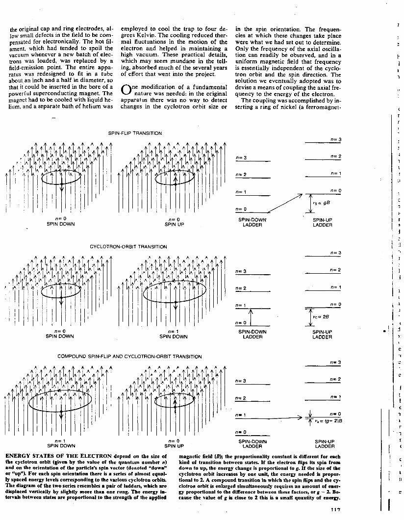
Three kinds of transition between states are possible in this system. Sup- pose the electron initially has its lowest- possible energy: its spin is down, so that its magnetic moment is parallel to the field, and its cyclotron orbit is the small- est one allowed, with n equal to 0. The electron therefore occupies the bottom rung of the lower energy ladder. A first transition would leave the spin orienta- tion fixed but would enlarge the orbit to the next allowed size; this transition cor- responds to climbing one rung of the same energy ladder, to the n = 1 state. The energy required to effect the change IS equal to the spacing between rungs and hence is given by 2 times the Bohr magneton times the field strength.
This level having been reached, an- other transition might flip the spin of the electron without altering the orbit, so that the electron would move from the n = 1 level of the spin-down ladder to the corresponding n = 1 level of the spin-up ladder. The energy required in this case is g times the Bohr magneton times the field strength. The third possi- bility is for the orbit to change size by one unit and for the spin to flip simul- taneously. For example, the electron might step from the n = 1 rung of the spin-down ladder directly to the n = 0 rung of the spin-up ladder. These levels almost coincide; the energy required to flip the spin to the antiparallel orienta- tion is almost made up by the energy liberated when the orbit shrinks by one unit. Only the small difference in energy between these quantities need be sup- plied. It is equal to (g - 2) times the Bohr magneton times the field strength.
The energy required for these changes of state is conveniently expressed in terms of the frequency of electromag- netic radiation that induces the tran- sition. Any frequency can be convert- ed into energy units by multiplying by Planck‘s constant, but for our purposes it is not even necessary to make the con- version. The frequency itself can be al- lowed to stand for the energy. The fre- quency needed to flip the spin is propor- tional to g, the constant that determines the difference in energy between spin states. In the same way the frequency of radiation that changes the cyclotron or- bit size by one unit is proportional to 2,
the constant that determines the spacing between rungs on a single energy ladder. For typical values of the applied mag- netic field both of these frequencies are, in the microwave region of the electro- magnetic spectrum. The difference be- tween them, which is called the anomaly frequency, induces the double transition where the spin and the orbital diameter change simultaneously. The anomaly frequency is therefore proportional to g - 2. Since g exceeds 2 by only about .1 percent, the anomaly frequency is smaller than the cyclotron-transition fre- quency by a factor of about 1,000.
he procedure for measuring the g T factor can now be given in terms of radiation frequencies. Two quantities must be determined: the cyclotron-tran- sition frequency and the anomaly fre- quency. The actual values of both fre- quencies depend on the strength of the magnetic field and on the value adopted for the Bohr magneton, and so they can- not be predicted beyond the accuracy with which these quantities are known. In the ratio of the two frequencies, how- ever, both of these factors cancel and the only significant quantities remaining are the proportionality constants that define the level spacings in the ladder diagram. For the anomaly frequency that constant is g - 2 and for the cyclo- tron-transition frequency it is exactly 2. Hence the ratio of the two frequencies equals (g - 2)/2. Multiplying by 2 and adding 2 gives the value of g itself.
This method of finding the g factor may seem needlessly roundabout. Why not just measure the spin-flip transi- tion frequency, which is directly pro- portional to g, and have the desired val- ue in a single step? One part of the an- swer lies in the substantial advantage to be found in working with a dimension- less ratio. Suppose the spin-flip frequen- cy were measured to an accuracy of eight decimal places. To find the g factor that frequency must then be multiplied by the Bohr magneton, by the strength of the applied magnetic field and by Planck’s constant. The eight decimal places would remain significant only if all these factors were known to at least the same accuracy. Taking the ratio of two frequencies eliminates all the extra- neous quantities, so that the precision of the frequency measurement alone deter- mines the accuracy of the result.
There is another argument in support of the indirect method. Because g is known to be very close to 2, deriving the value of g from a measurement of g - 2 yields a large divident in accuracy. If (g - 2)/2 is known to eight significant figures, then multiplying by 2 and add- ing 2 yields a value of g accurate to 11 significant figures. This seeming par- adox of accuracy obtained at no cost can be resolved in a number of ways. One explanation is that the anomaly fre- quency is 1,000 times smaller than the
109
spin-flip frequency, so that a measure- ment with a given fractional accuracy yields a much smaller uncertainty in terms of cycles per second. Another ap- proach is to point out that in any mea- surement of the anomaly frequency the cyclotron-orbit level spacing of exactly 2 is subtracted by the physical system itself and not by the experimenter; as a result only the small discrepancy from 2 need be measured. The situation of the experimenter is somewhat like that of a surveyor asked to lay out a course of 1,001 meters. The distance could be measured meter by meter, but high ac- curacy could be achieved more easily with a chain known to be exactly one kilometer long. That distance could then be subtracted from the total and only one meter would have to be measured with high precision.
he procedure adopted at the Uni- T versity of Washington for measuring the g factor can be summarized as fol- lows. First an electron is captured in a uniform magnetic field and then its mo- tion in the field is analyzed in order to determine two quantities: the frequency of applied radiation that changes the or- bit size and the frequency that induces a simultaneous change in orbit size and spin orientation. From the ratio of these frequencies g can be found through triv- ial arithmetical operations. This synop- sis does indeed set forth the principles of the experiment, but it is rather like the famous recipe for elephant stew that begins, “Take one medium elephant.. . .** Most of the work has been left out, and much of the adventure.
One deficiency of the experiment as it has been described so far is that the
SIGNAL GENERATOR
I
SIGNAL DETECTOR
electron is not trapped by the magnetic field alone. In a uniform magnetic field the electron cannot migrate across the field lines, but there is nothing to prevent it from drifting parallel to the field and thereby escaping. Something is needed to seal the ends of the trap; what we chose at the University of Washington was an electric field superposed on the magnetic field, in a configuration called a Penning trap.
The electric field is formed by volt- ages applied to three electrodes, name- ly a cap at each end of the trap and a ring that girdles the midplane. Both caps are given a negative electric charge and the ring is given a positive charge. In the resulting combination of electric and magnetic fields the electron is confined in three dimensions. If it drifts horizon- tally, the magnetic field diverts it into a circular orbit. If it wanders vertical- ly, parallel to the magnetic-field lines, it is reflected by the electric field on ap- proaching the repulsive, negative charge of the cap electrode.
In general an electron reflected from one cap electrode will overshoot the midplane and then be repelled by the field at the opposite end of the trap, only to overshoot the midplane once again. In this way an oscillation along the sym- metry axis of the trap can arise. If the frequency of the oscillation is to be in- dependent of the amplitude, the elec- trodes must have a certain shape. They must be hyperboloids with cylindrical symmetry around the axis of the trap.
The addition of the electric field com- plicates the motion of a trapped particle. The electron continues to execute the rapid circles around magnetic-field lines that constitute the cyclotron motion. Su-
SIGNAL GENERATOR
t W
ELECTRODE CAPACITANCE
VOLTAGE
EMPTY TRAP
SIGNAL DETECTOR
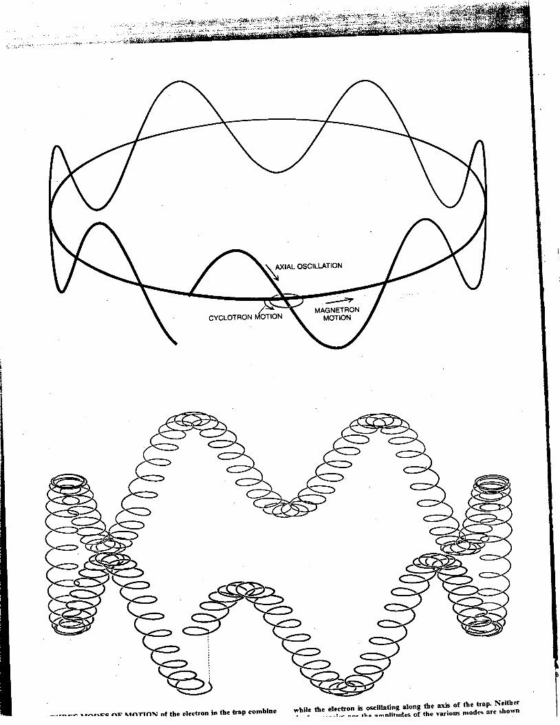
perposed on that orbital velocity there is now an axial oscillation parallel to the magnetic-field lines. In addition the interaction of the electric and the mag- netic fields gives rise to a third mode of motion. The electric field not only sup- plies a restoring force that confines the electron along the symmetry axis but also has a radial component that tends to push the electron away from the cen- ter of the trap and toward the ring elec- trode. This radial force might allow the electron to escape if it were not for the magnetic field, which overcomes it through the same mechanism that gen- erates the cyclotron rotation. The radial force acting on the electron is converted by the magnetic field into a circumferen- tial drift, so that the electron is deflected into a circular path.
This last perturbation imposed on the electron’s trajectory is called the magne- tron motion, after the kind of micro- wave-generating device in which it plays an important part. The magnetron orbit is much larger than the cyclotron orbit, but the electron moves around it much slower. (“Large” and “slow” are appro- priate here only for purposes of com- parison. The electron typically executes some 3 5,000 magnetron revolutions per second, but in each of those revolutions it completes 1.4 million cyclotron or- bits.) The magnetron motion slightly modifies all the energy states of the elec- tron, shifting the levels in the ladder dia- gram. The shifts are small, however, and they can be calculated as well as mea- sured experimentally. Hence in a preci- sion measurement of the g factor it is possible to correct for the effects of the magnetron motion.
The trajectory of the electron in the
SIGNAL
ELECTRODE CAPACITANCE
TRAP WITH ELECTRON
SIGNAL DETECTOR
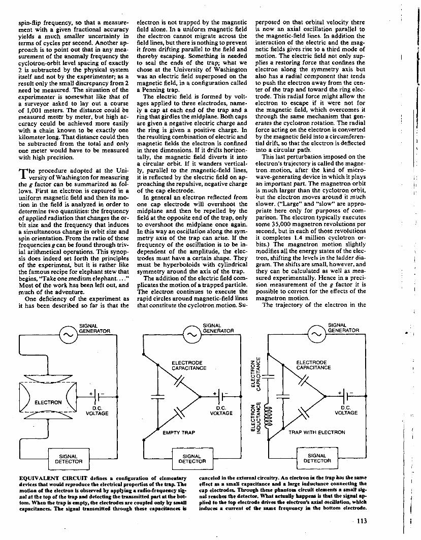
EQUIVALENT CIRCUIT defines a configuration of elementary devices that would reproduce the electrical properties of the trap. The motion of the electron is observed by applying a radio-frequency sip- nal at the top of the trap and detecting the transmitted part at the bot- tom. When the trap is empty, the electrodes are coupled only by small capacitances. The signal tmnsmitted through these capacitances is
canceled in the external circuitry. An electron in the trap has the same effect as a small capacitance and a large inductance connecting the cap electrodes. Through these phantom circuit elements a small sig- nal reaches the detector. What actually happens is that the signal a p plied to the top electrode drives the ele&oo’s axial oscillation, which induces a current of the same frequency in the bottom electrode,
113
,
I 1 -
\
I
>
, .
1
5 10 15 20 25 TIME (MINUTES)
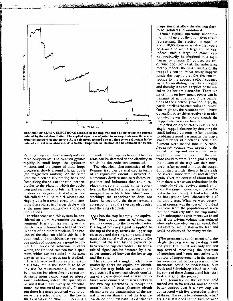
RECORD OF SEVEN ELECTRONS confined in the trap was made by detecting the current induced by the axial oscillation. The applied signal was adjusted to an amplitude near the maxi- mum the electrons could tolerate. As the electrons escaped one at a time seven reductions in the induced current were observed. At a smaller amplitude an electron can be confined for weeks.
Penning trap can thus be analyzed into three components. The electron gyrates rapidly in small loops (the cyclotron motion), and the center of these loops progresses slowly around a larger circle (the magnetron motion). At the same time the electron is vibrating back and forth along the axis of the trap, perpen- dicular to the plane in which the cyclo- tron and magnetron orbits lie. The total motion is analogous to that of a carnival ride called the Tilt-a-Whirl, where a car- riage pivots in a small circle on a turn- table that rotates in a larger circle while at the same time riding over a series of undulations.
In what sense can this system be con- sidered an atom, warranting the name geonium? It is atomlike mainly in that the electron is bound to a field of force like that of an atomic nucleus. The mo- tion of the electron within this field is quantized, and transitions between vari- ous modes of motion correspond to defi- nite frequencies of radiation. In other words, the trapped electron has a spec- trum, which can be studied in the same way as an atomic spectrum is studied.
It is all very well to create an artifi- cial atom, but if the atom is to be of any use for measurements, there must be a means for observing its spectrum. A single atom cannot emit or absorb much radiation; indeed, the quantity is so small that it can hardly be detected, much less measured accurately. It turns out there is a more practical way to ob- serve the electron’s motion; the key is the axial vibration. which indiices small
currents in the trap electrodes. The cur- rents can be detected in the circuitry to which the electrodes are connected.
The electrical characteristics of the Penning trap can be analyzed in terms of an equivalent circuit: a network of elementary devices such as resistors, ca- pacitors and inductors that could re- place the trap and mimic all its proper- ties. In this kind of analysis the trap is imagined as a black box whose inner workings the experimenter does not know; he sees only the three terminals corresponding to the two cap electrodes and the ring electrode.
hen the trap is empty, the equiva- W lent circuit consists of small ca- pacitors connecting the three electrodes. If a high-frequency signal is applied to the top of the trap, across the upper cap electrode and the ring, some small rem- nant of the signal will be conveyed to the bottom of the trap by the capacitance between the cap electrodes. The trans- mitted signal can be detected by a re- ceiver connected between the lower cap and the ring.
The capture of a single electron dra- matically alters the equivalent circuit. When the trap holds an electron, the trap acts as if a resonant circuit consist- ing of a capacitance and a large induc- tance were connected in series between the two cap electrodes. Although the contribution of these phantom circuit elements to the transmission of the sig- nal is weaker than that of the trap ca- nncitancp the new nath hac dictinrtive
properties that allow the electron signal to be isolated and monitored.
Under typical operating conditions the inductance of the equivalent circuit representing the electron is equal to about 10,000 henries, a value that would be associated with a large coil of wire; indeed, such a large inductance can- not ordinarily be obtained in a high- frequency circuit. Of course, the coil of wire does not exist; the inductance merely reflects the small inertia of the trapped electron. What really happens inside the trap is that the electron re- sponds to the applied radio-frequency signal by oscillating in synchrony with it and thereby induces a replica of the sig- nal in the bottom electrodes. There is a strict limit on how much power can be transmitted in this way: if the oscilla- tions of the electron grow too large, the particle strikes the electrodes and is lost. One might say the resonant circuit burns out easily. A sensitive receiver is needed to detect even the largest signals the trapped electron can handle.
We first observed clear evidence of a single trapped electron by detecting the small induced currents. After pumping to obtain a good vacuum in the trap a small number of electrons from a hot filament were loaded into it. A radio- frequency voltage was applied to the top of the trap and was adjusted to an amplitude near the maximum the elec- trons could tolerate. The signal reaching the bottom of the trap was then moni- tored. After several minutes the output diminished a little, then it held steady for several more minutes and dropped again. Over the course of about half an hour there were seven reductions in the magnitude of the received signal, all of about the same magnitude, and after the last reduction the signal had returned to the background level characteristic of the empty trap. What we were observ- ing, of course, was the loss of individual electrons from the population of seven that had evidently filled the trap initial- ly. In subsequent experiments we found that if the driving voltage was reduced when only one electron remained, that last electron would stay in the trap and could be observed for many weeks.
he permanent confinement of a sin- T gle electron was an exciting result and great fun, but it was only the first step toward measuring the spectrum of geonium and hence measuring g. A number of improvements in the appara- tus were needed before precision mea- surements could be undertaken; Van Dyck and Schwinberg joined us in mak- ing some of these changes, and later they took charge of the project.
The geometry of the electric field turned out to be critical, and to obtain better control over it a new trap was constructed with five electrodes instead of three. The extra two elements, which are rinm ctatinnpd in the oanc hptwppn
I fie original cap and ring electrodes, al- low small defects in the field to be com- pensated for electronically. The hot fil- ament, which had tended to spoil the vacuum whenever a new batch of elec- trons was loaded, was replaced by a field-emission point. The entire appa- ratus was redesigned to fit in a tube about an inch and a half in diameter, so that it could be inserted in the bore of a powerful superconducting magnet. The magnet had to be cooled with liquid he- lium, and a separate bath of helium was
employed to cool the trap to four de- grees Kelvin. The cooling reduced ther- mal fluctuations in the motion of the electron and helped in maintaining a high vacuum. These practical details, which may seem mundane in the tell- ing, absorbed much of the several years of effort that went into the project.
ne modification of a fundamental 0 nature was needed: in the original apparatus there was no way to detect changes in the cyclotron orbit size or
in the spin orientation. The frequen- cies at which these changes take place were what we had set out to determine. Only the frequency of the axial oscilla- tion can readily be observed, and in a uniform magnetic field that frequency is essentially independent of the cyclo- tron orbit and the spin direction. The solution we eventually adopted was to devise a means of coupling the axial fre- quency to the energy of the electron.
The coupling was accomplished by in- serting a ring of nickel (a ferromagnet-
SPIN-FLIP TRANSITION n= 3
n= 2 n= 3
n= 0 SPIN DOWN
n= 0 SPIN UP
SPIN-UP SPIN-DOWN LADDER LADDER
CYCLOTRON-ORBIT TRANSITION n= 3
I r i .
I i 1 1
n= 2 n= 3
I n= 1 n= 2
n= 1 n= 0 7 T
u c u 28 1 SPIN-DOWN SPIN-UP
LADDER LADDER n= 0
SPIN DOWN n= 1
SPIN DOWN
COMPOUND SPIN-FLIP AND CYCLOTRON-ORBIT TRANSITION n= 3
n= 2 n= 3
1 1 E
1 L r
‘ 7 I
I C ‘ c
; 1 : 11
I _
I
i: n= 2 n= 1
n= 0
SPIN-DOWN LADDER
n= 0 SPIN UP
n= 1 SPIN DOWN
SPIN-UP LADDER
ENERGY STATES OF THE ELECTRON depend on the size of the cyclotron orbit (given by the value of tbe quantum number n) and on the orientation of the particle’s spin vector (denoted “down” or ‘‘up“). For each spin orientation there is a series of almost equal- ly spaced energy levels corresponding to the various cyclotron orbits. The diagram of the two series resembles a pair of ladders, which are displaced vertically by slightly more than one rung. The energy in- tervals between states are proportional to the strength of the applied
magnetic field (B); the proportionality constant is different for each kind of transition between states. If the electron flips its spin from down to up, tbe energy change is proportional to g. If tbe size of the cyclotron orbit increases by one unit, the energy needed is propor- tional to 2. A compound transition in which the spin Rips and the cy- clotron orbit is enlarged simultaneously requires an amount of ener- gy proportional to tbe difference between these factors, or g - 2. Be- cause the value of g is dose to 2 this is a small quantity of energy.
1 1 7

ic metal) in the midplane of the trap, encircling the original ring electrode. The nickel ring had the effect of bow- ing the magnetic field at the midplane, so that it was somewhat more intense near the ends of the trap; the resulting configuration is called a magnetic bot- tle. If there were no axial oscillation, so that the electron remained in the midplane, the magnetic bottle would have no effect. On each excursion away from the midplane, however, the slight convergence of the magnetic-field lines tends to reinforce the effect of the electric field in pushing the electron back toward the central plane. As a re- sult of this additional restoring force the frequency of the axial oscillation is increased.
The total strength of the interaction between the electron and the distorted magnetic field depends on the energy of the cyclotron orbit and on the spin orientation. The influence of the field is greater when the orbit is larger or when the spin is up. For this reason the magni-
tude of the axial frequency shift changes with each change in the cyclotron orbit size or in the spin state. The distortion of the magnetic field must be kept small or the energy levels under examination will be too greatly modified, but only a small shift in the axial frequency is needed in order to make the changes in quantum state observable. Typically the axial os- cillation has a frequency of 60 mega- hertz and the frequency shift caused by the magnetic bottle is a few hertz.
In an ideal experiment the electron would maintain a steady motion in a particular cyclotron orbit and a partic- ular spin orientation until the experi- menter supplied the energy needed to change the state. A graph of the energy of the electron as a function of time would therefore show a series of precise steps, all taken under the experimenter’s control, and would be flat between the steps. A real experiment is quite differ- ent. Even at four degrees K. the thermal agitation of the electron has an average energy equivalent to a few rungs on the
MAGNETIC-FIELD LINES
MAGNETIC BOTTLE is created in the trap by a ring of nickel (a ferromagnetic metal), which slightly distorts the uniform imposed magnetic field. Because of the ring the field lines are bowed outward at the midplane and effectively converge toward the ends of the trap. This ta- pering of the field contributes an extra restoring force to the axid oscillation of the electron. The magnitude of the force depends on the size of the cyclotron orbit and on the spin ori- entation, so that changes in those quantities give rise to slight shifts in the frequency of the axial oscillation. As a consequence of this coupling of the three modes of motion, the ener- gy state of the electron can be determined by monitoring the frequency of the axial oscillation.
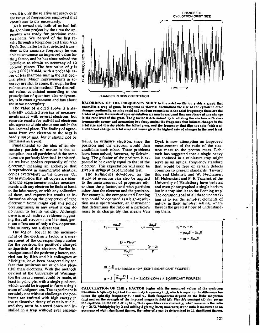
ladder of cyclotron states. Because of these random thermal disturbances the electron is constantly moving up and down whichever ladder it happens to be on. The resulting graph of energy as a function of time resembles a crop of grass: the root level corresponds to the lowest rung on the ladder and the blades of grass are energy excursions to higher rungs. Any measurement of the energy levels must be made against a background of this thermal noise.
The measurement is made by careful- ly searching for the frequencies that work the largest change on the rapidly fluctuating pattern. First a signal with a frequency near the cyclotron-transi- tion frequency is supplied and the aver- age height of the “grass” is monitored. The applied signal is then tuned slow- ly through a narrow range of frequen- cies. When the frequency corresponds exactly to the interval between rungs on the ladder, the electron absorbs ener- gy strongly and climbs at least several rungs. Thus the cyclotron-transition fre- quency is the frequency that gives the tallest grass.
In the measurement of the anomaly frequency the background of thermal noise is less disruptive. The transition to be observed in this case is a compound one (both the spin and the orbit must change), and it is much less likely to hap- pen spontaneously. In general the spin does not flip unless the experimenter does something to cause it to flip, and so all the electron’s thermal transitions are normally confined to just one of the lad- ders in the energy diagram. To induce the lateral transition between ladders a strong signal must be supplied.
How does the experimenter know the orientation of the spin at any given mo- ment, or in other words how does he know which ladder the electron is on? The needed information can be found in the energy diagram itself: the spin-down ladder, it will be remembered, extends about one full rung lower than the spin- up ladder. The root level of the grass therefore lies at a lower energy when the spin is down. The anomaly frequency is the frequency that changes the root level most often.
When both the cyclotron-transition frequency and the anomaly frequency have been measured, it remains only to divide, multiply by 2 and add 2 in or- der to calculate g. The two frequencies can be determined precisely, even in the noisy background, because both the res- onances are very sharp, that is, a small change in the applied frequency causes a large change in the rate at which transi- tions are observed. The instrument with which the frequencies are generated is ultimately based on a cesium atomic clock, but even the absolute calibration of the instrument does not limit the accuracy of the measurement. Because both frequencies are generated by the same instrument and only the ratio mat-
ters, it is only the relative accuracy over the range of frequencies employed that contributes to the uncertainty. AS it turned out, both of us had left
b e geonium project by the time the ap- paratus was ready for precision mea- surements. We learned of the first re- sults through a telephone call from Van Dyck. Soon after he first detected transi- tions at the anomaly frequency he was able to announce an improved value for the g factor, and he has since refined the technique to obtain an accuracy of 10 decimal places. The best value of g is now 2.0023 193044, with a probable er- ror of less thanane unit in the last deci- mal place. Major improvements in ac- curacy are still to come, through further refinements in the method. The theoreti- cal value, calculated according to the prescription of quantum electrodynam- ics, is in exact agreement and has about the same uncertainty.
The value of g cited above is a sta- tistically weighted average of measure- ments made with several electrons, but separate results for individual electrons also agree to within about one unit in the last decimal place. The finding of agree- ment from one electron to the next is hardly surprising, but it should not be dismissed as trivial.
Fundamental to the idea of an ele- mentary particle of matter is the as- sumption that all particles with the same name are perfectly identical. In this arti- cle we have spoken repeatedly of “the electron,” meaning an archetype that is reproduced in innumerable identical copies everywhere in the universe. On the assumption that all copies are iden- tical the experimenter makes measure- ments with any electron he finds at hand in the laboratory, or with any collection of them, and reports his results as in- formation about the properties of “the electron.” Some might call this policy presumptuous; in any event it can do no harm to test its validity. Although there is much indirect evidence suggest- ing that all electrons are identical, geo- nium offers one of only a few opportun- ities to carry out a direct test.
The logical sequel to the measure- ment of the electron g factor is a mea- surement of the corresponding number for the positron, the positively charged antiparticle of the electron. Earlier in- vestigations of the positron g factor, car- ried out by Rich and his colleagues at Michigan, have been hampered by the fact that positrons are much less plen- tiful than electrons. With the methods devised at the University of Washing- ton the measurement could be made, at least in principle, with a single positron, which would be trapped to form a single atom of antigeonium. The experiment is certainly not without challenge: the pos- itrons are emitted with high energy in the radioactive decay of certain nuclei, and they must be slowed down and in- stalled in a trap without ever encoun-
CHANGES IN CYCLOTRON-ORBIT SIZE
t t
z E
i m > 0
3 (3 W
-I
X 9 a
. . , TIME j Y
CHANGES IN SPIN ORIENTATION
RECORDING OF THE FREQUENCY SHIFT in the axial oscillation yields a graph that resembles a crop of grass. In response to thermal fluctuations the size of the cyclotron orbit changes continually, causing rapid and random excursions in the uipl frequency; these are the blades of gper. Reversclls of spin orientation are much mer, and they are observed as a change h the mot level of the grass. ”be g factor is determined by irradiating the electron with elec- tromagnetic energy and measuring two frequencies: the frequency that induces changes in the orbit size and thereby yields the tallest grass, and the frequency that Bips the spin (with a si- multaneous change in orbit size) and hence gives the highest rate of changes in the root level.
tering an ordinary electron, since the positron and the electron would then annihilate each other. These problems have been solved, however, by Schwin- berg. The g factor of the positron is ex- pected to be exactly equal to that of the electron. This expectation will soon be given a stringent experimental test.
The techniques developed for the study of geonium can also be applied to the measurement of properties oth- er than the g factor, and with particles other than the electron and the positron. For example, the compensated Penning trap could be operated as a high-resolu- tion mass spectrometer, an instrument that determines the ratio of a particle’s
Dyck is now attempting an improved measurement of the ratio of the elec- tron mass to the proton mass. Deh- melt has suggested that a single heavy ion confined in a miniature trap might serve as an optical frequency standard that would be free of certain defects common to present standards. Toward this end Dehmelt and W. Neuhauser, M. Hohenstatt and P. E. Toschek of the University of Heidelberg have isolated and even photographed a single barium ion in a trap similar to the Penning trap. The common goal of all these undertak- ings is to see the simplest elements of nature in their simplest setting, where there is the greatest h o w of understand-
mass to its charge. By this mdans Van ing them. - b
(9-2)=1.1596522 x 10⁻³ [EIGHT SIGNIFICANT FIGURES] 2
= 2 [@+I] + 2 = 2.oo23193o44 [ii SIGNIFICANTFWRES~
CALCULATION OF THE g FACTOR begins with the measured values of the cyclotron transition frequency ( W J and the anomaly frequency (wa), which is equal to the difference be- tween the spin-flip frequency ( w J and y,. Both frequencies depend on the Bohr magneton ( p ~ ) and on the strength of the imposed magnetic field (B); Planck’s constant (/I) also enters the equation. In the ratio of Y , to Y , these quantities cancel exactly; what remains is the ratio (g - 2112. Multiplying by 2 and adding 2 gives g itself; moreover, if the ratio is measured to an ~ccurrcy of eight significant figures, the value of g can be determined to 11 significant figures.