the islamic university of gaza faculty of engineering approaches to groundwater modeling conceptual...
TRANSCRIPT

The Islamic University of GazaFaculty of Engineering
Approaches to Groundwater Modeling
Conceptual Model

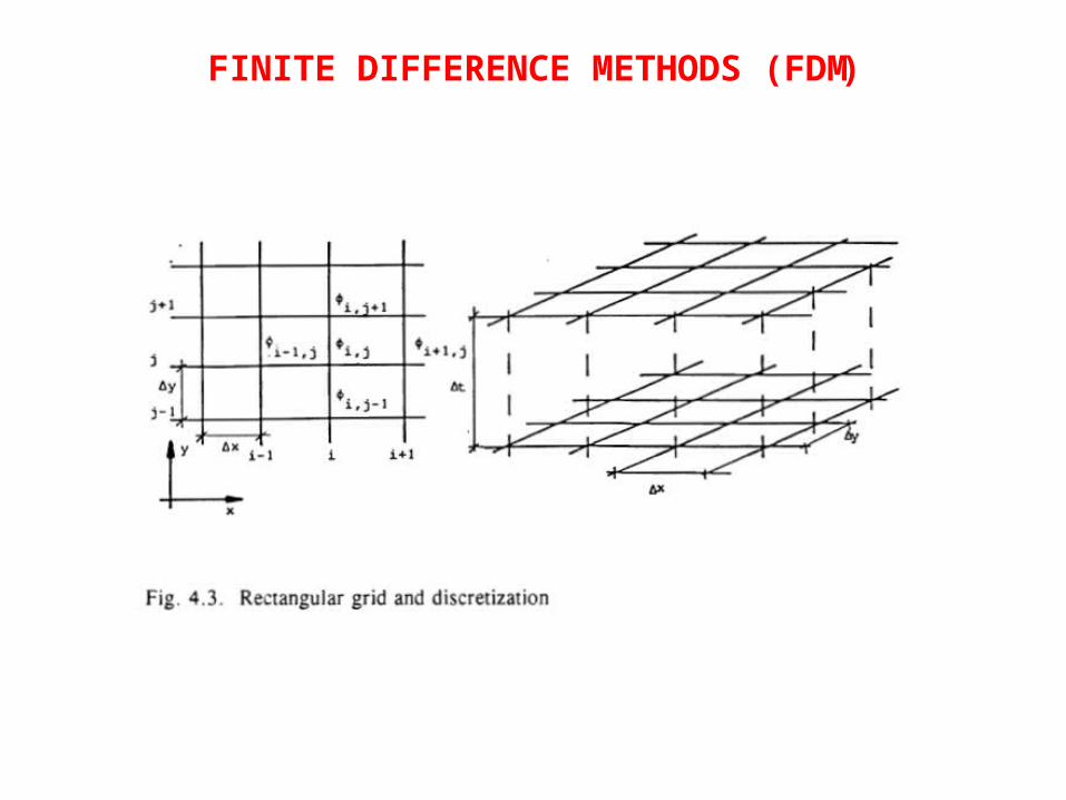
(FINITE DIFFERENCE METHODS (FDM
- -The base of a difference method is the approximation of differentials by differences, using a rectangular (or even better a squared) grid
with mesh size Ax and Ay .
- -At each grid point or node the hydrogeological parameters like conductivity, thickness of layer, storativity, etc. are specified together with the
external flows like infiltration, pumping rates, etc .
(FINITE DIFFERENCE METHODS (FDM
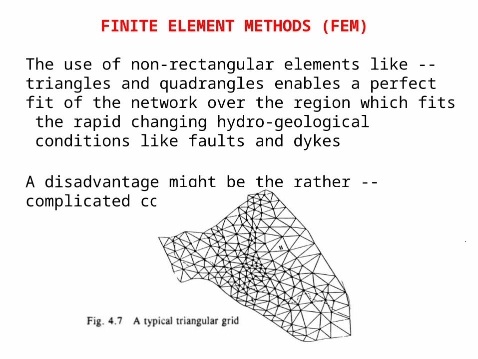
FINITE ELEMENT METHODS (FEM(
- -The use of non-rectangular elements like triangles and quadrangles enables a perfect fit of the network over the region which fits the rapid changing hydro-geological conditions like faults and dykes
- -A disadvantage might be the rather complicated computational framework
.
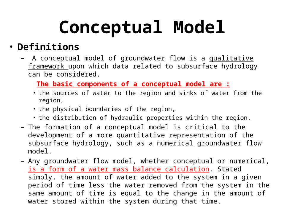
Conceptual Model• Definitions
– A conceptual model of groundwater flow is a qualitative framework upon which data related to subsurface hydrology can be considered.
The basic components of a conceptual model are :• the sources of water to the region and sinks of water from the region,
• the physical boundaries of the region,
• the distribution of hydraulic properties within the region.
– The formation of a conceptual model is critical to the development of a more quantitative representation of the subsurface hydrology, such as a numerical groundwater flow model.
– Any groundwater flow model, whether conceptual or numerical, is a form of a water mass balance calculation. Stated simply, the amount of water added to the system in a given period of time less the water removed from the system in the same amount of time is equal to the change in the amount of water stored within the system during that time.

CONCEPTS OF MODELLING
.
Data requirements to define and validate a model are:
1. Physical data:
- Geologic maps and cross sections, indicating the horizontal and vertical extend of the system and its boundaries.
- Topographic maps showing surface water bodies, springs, sinks and divides.
- Isomaps showing the elevations of the various permeable and confining layers.
- Geomorphologic maps, showing the extend and thickness of river and lake deposits

CONCEPTS OF MODELLING
.
Data requirements to define and validate a model are:
2. Hydrogeological data
-Isohypse maps, showing the water tables for the various layers
- Conductivity, transmissivity and storativity maps for the various layers
- Conductivities of stream and lake sediments
- Spatial and temporal distribution of hydrological stressesevapotranspiration, recharge, pump rates, spring flow and
surface-groundwater interactions.

Logical Steps in Defining a Conceptual Model
.
1. Identification of the boundaries of the model
Preferably natural hydro-geologic boundaries are selected like water divides, large water bodies or impermeable formations.
Boundary conditions are defined for each layer in terms of predefined flows, levels or flow-level relations
Logical Steps in Defining a Conceptual Model
.
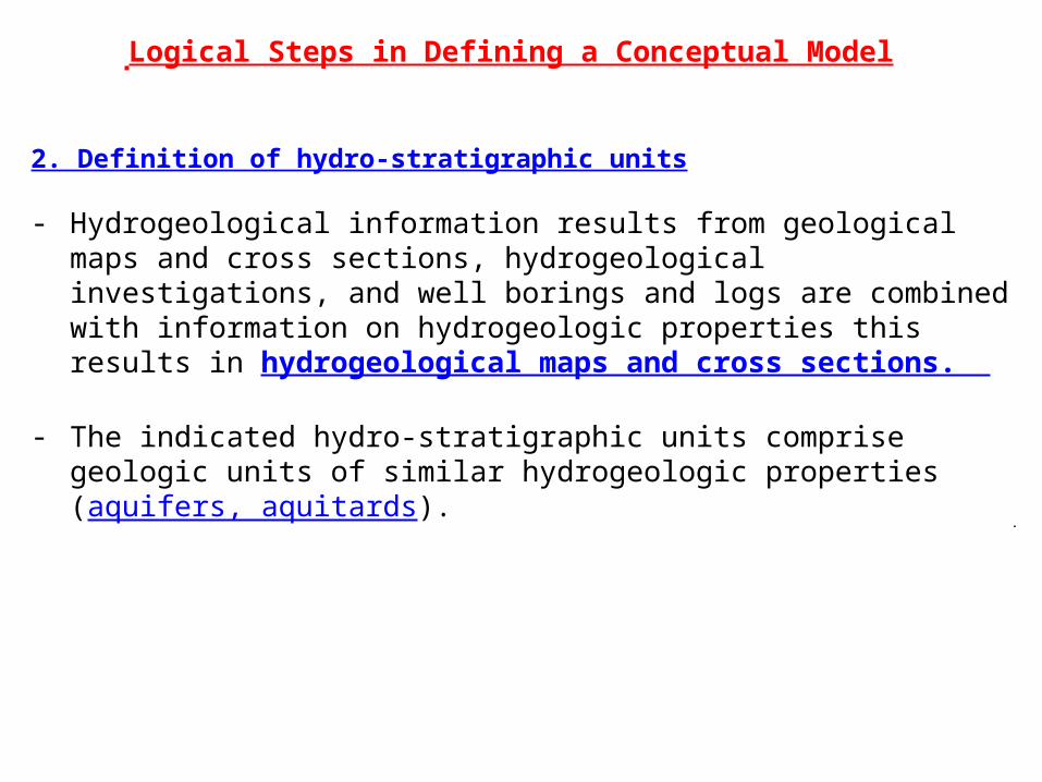
2. Definition of hydro-stratigraphic units
- Hydrogeological information results from geological maps and cross sections, hydrogeological investigations, and well borings and logs are combined with information on hydrogeologic properties this results in hydrogeological maps and cross sections.
- The indicated hydro-stratigraphic units comprise geologic units of similar hydrogeologic properties (aquifers, aquitards).

Logical Steps in Defining a Conceptual Model
.
Logical Steps in Defining a Conceptual Model
.
3. Determination of the water budget:
-Groundwater recharge can be estimated from net precipitation, return flows and surface water interactions.
-Outflows are found from springs, base flow to streams, pumping and in case of shallow water tables evapotranspiration.
-The change in storage is found from the change in water tables.
Model Concepts
.
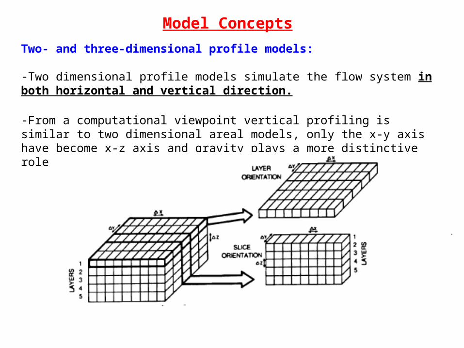
Two- and three-dimensional profile models:
-Two dimensional profile models simulate the flow system in both horizontal and vertical direction.
-From a computational viewpoint vertical profiling is similar to two dimensional areal models, only the x-y axis have become x-z axis and gravity plays a more distinctive role
Model Concepts
.
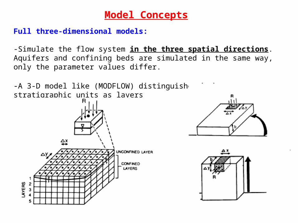
Full three-dimensional models:
-Simulate the flow system in the three spatial directions. Aquifers and confining beds are simulated in the same way, only the parameter values differ.
-A 3-D model like (MODFLOW) distinguishes hydro-stratigraphic units as layers
GRIDS
.
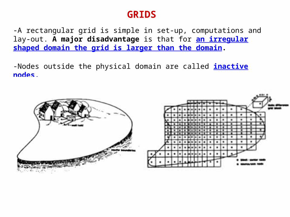
-A rectangular grid is simple in set-up, computations and lay-out. A major disadvantage is that for an irregular shaped domain the grid is larger than the domain.
-Nodes outside the physical domain are called inactive nodes.

GRIDS
.
-Finite element methods in general apply triangular or quadrangular based elements. although complex linear and non-linear have been applied as well.

Selection Of Grids
.
-A finer spacing (dense grid( is required with spatial rapidly changing flow conditions like a steep curved water table surface or a strong variability of hydro-geologic parameters or hydrologic stresses like infiltration and pump rates, close to the rivers.

.
Boundary Conditions
.
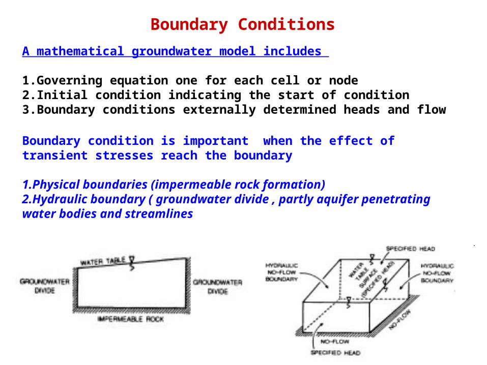
A mathematical groundwater model includes
1.Governing equation one for each cell or node2.Initial condition indicating the start of condition3.Boundary conditions externally determined heads and flow
Boundary condition is important when the effect of transient stresses reach the boundary
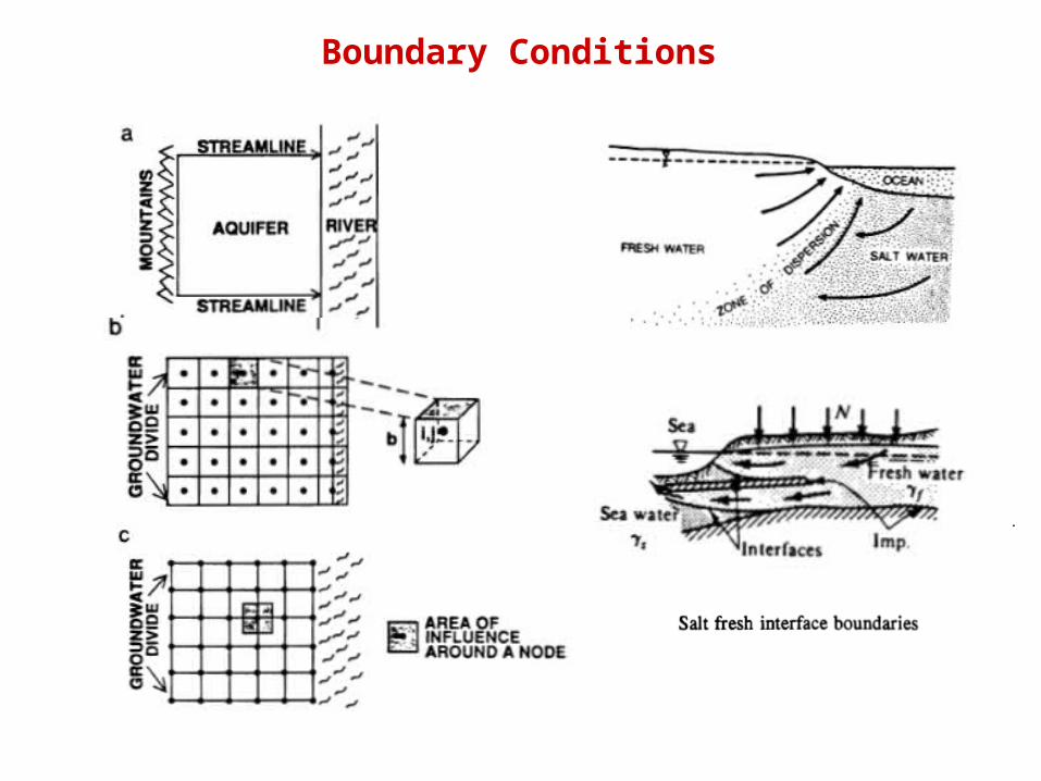
1.Physical boundaries (impermeable rock formation)2.Hydraulic boundary ( groundwater divide , partly aquifer penetrating water bodies and streamlines
Boundary Conditions
.
Software
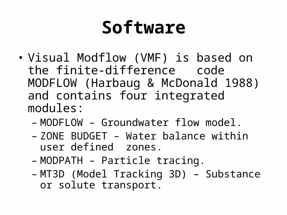
• Visual Modflow (VMF) is based on the finite-difference code MODFLOW (Harbaug & McDonald 1988) and contains four integrated modules:– MODFLOW – Groundwater flow model.– ZONE BUDGET – Water balance within user
defined zones.– MODPATH – Particle tracing.– MT3D (Model Tracking 3D) – Substance or solute
transport.

Typical MODFLOW grid and lay-out
.
Active cell
In active cell

Conceptual ModelExample: North Gaza
• Model Domain and Boundariesthe model domain is usually chosen to fit stable boundary conditions.
Example:
The Model Domain encloses an area of 17x23 km in the northern part of the Gaza Strip

Conceptual ModelExample: North Gaza
• Model Grid The model domain is divided into a horizontal grid with cell size 50x50 m at the
BLWWTP site and 20x20 m at the new NGWWTP site and the cell size then increases gradually towards the model boundaries
NGWWT Site
BLWWT Site

Conceptual Model
Boundaries– No-flow Boundary
• Usually taken normal to water level contours
– Constant head boundary• Where head is expected to be constant (no change)
during the model simulation duration• Examples ???
– Variable head boundary• Usually taken when head is changing uniformly with
time • Examples (river ?)

Conceptual Model
• The lower boundary of the model consists of Saqiye’s surface • The upper boundary is the ground surface
Water Table
Conceptual Model
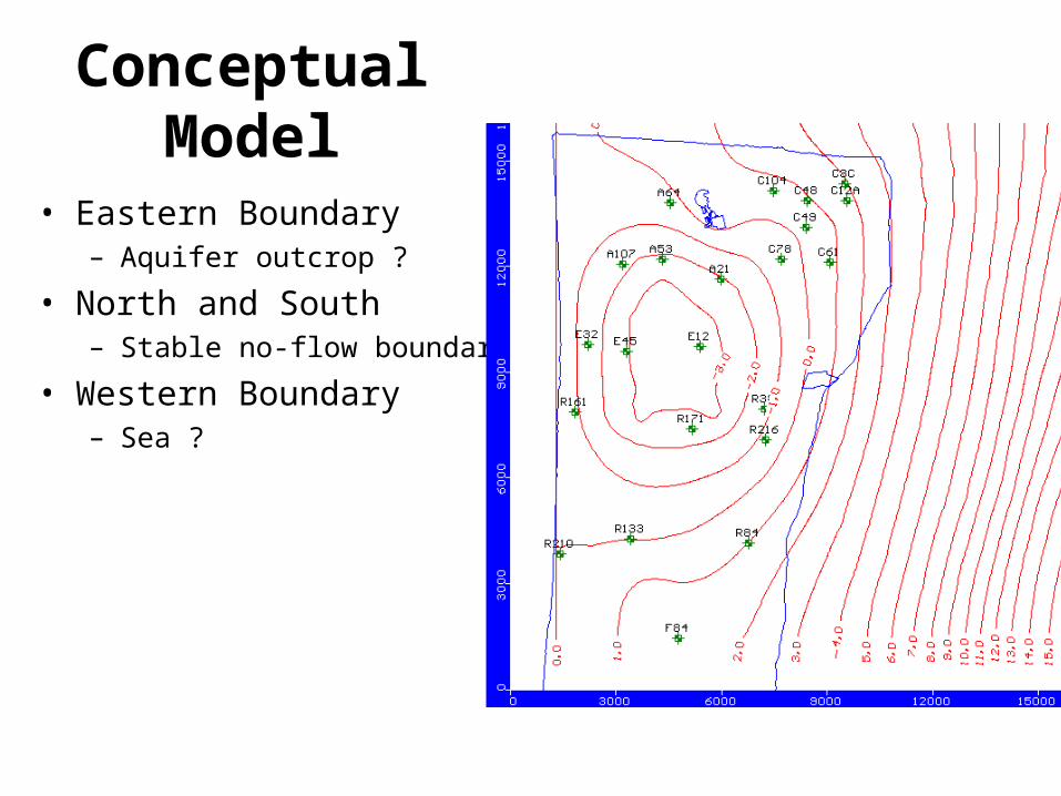
• Eastern Boundary– Aquifer outcrop ?
• North and South– Stable no-flow boundaries
• Western Boundary– Sea ?

Exercise – Steady State Model• Develop a one layer flow model for 1km*1km*80m rectangular aquifer
(50mx50m cells)
• Boundaries:”
– Western: constant head = 0 m
– Eastern: constant head = 5m
– North and south: no flow
• Recharge: 200mm/year
• Kx=30m/d, Ky=10m/d
• One well:
– Screen: -5 m , -35m, Q = 2000m3/day
• View the results: Water level, cross section, flow direction, etc
• Refine the grid around the well
• Add layer & Change properties in the layers