the internet of things - wordpress.com · 2018-05-14 · 3.3 bacnet security 55 3.4 bacnet over web...
TRANSCRIPT

P1: TIX/XYZ P2: ABCJWST118-fm JWST118-Hersent November 30, 2011 8:50 Printer Name: Yet to Come
THE INTERNETOF THINGS

P1: TIX/XYZ P2: ABCJWST118-fm JWST118-Hersent November 30, 2011 8:50 Printer Name: Yet to Come
THE INTERNETOF THINGSKEY APPLICATIONS ANDPROTOCOLS
Olivier HersentActility, France
David BoswarthickETSI, France
Omar ElloumiAlcatel-Lucent, France
A John Wiley & Sons, Ltd., Publication

P1: TIX/XYZ P2: ABCJWST118-fm JWST118-Hersent November 30, 2011 8:50 Printer Name: Yet to Come
This edition first published 2012© 2012 John Wiley & Sons Ltd
Registered officeJohn Wiley & Sons Ltd, The Atrium, Southern Gate, Chichester, West Sussex, PO19 8SQ, United Kingdom
For details of our global editorial offices, for customer services and for information about how to apply forpermission to reuse the copyright material in this book please see our website at www.wiley.com.
The right of the author to be identified as the author of this work has been asserted in accordance with the Copyright,Designs and Patents Act 1988.
All rights reserved. No part of this publication may be reproduced, stored in a retrieval system, or transmitted, in anyform or by any means, electronic, mechanical, photocopying, recording or otherwise, except as permitted by the UKCopyright, Designs and Patents Act 1988, without the prior permission of the publisher.
ETSI logo reproduced by kind permission of © ETSI, All Rights Reserved.
Wiley also publishes its books in a variety of electronic formats. Some content that appears in print may not beavailable in electronic books.
Designations used by companies to distinguish their products are often claimed as trademarks. All brand names andproduct names used in this book are trade names, service marks, trademarks or registered trademarks of theirrespective owners. The publisher is not associated with any product or vendor mentioned in this book. Thispublication is designed to provide accurate and authoritative information in regard to the subject matter covered. It issold on the understanding that the publisher is not engaged in rendering professional services. If professional adviceor other expert assistance is required, the services of a competent professional should be sought.
Library of Congress Cataloging-in-Publication Data
Hersent, Olivier.The internet of things : key applications and protocols / Olivier Hersent,
David Boswarthick, Omar Elloumi.p. cm.
Includes bibliographical references and index.ISBN 978-1-119-99435-0 (hardback)1. Intelligent buildings. 2. Smart power grids. 3. Sensor networks. I. Boswarthick, David.
II. Elloumi, Omar. III. Title.TH6012.H47 2012681′.2–dc23
2011037210
A catalogue record for this book is available from the British Library.
ISBN: 9781119994350 (H/B)
Typeset in 10.5/13pt Times by Aptara Inc., New Delhi, India

P1: TIX/XYZ P2: ABCJWST118-fm JWST118-Hersent November 30, 2011 8:50 Printer Name: Yet to Come
Contents
List of Acronyms xv
Introduction xxiii
Part I M2M AREA NETWORK PHYSICAL LAYERS
1 IEEE 802.15.4 31.1 The IEEE 802 Committee Family of Protocols 31.2 The Physical Layer 3
1.2.1 Interferences with Other Technologies 51.2.2 Choice of a 802.15.4 Communication Channel, Energy
Detection, Link Quality Information 71.2.3 Sending a Data Frame 8
1.3 The Media-Access Control Layer 81.3.1 802.15.4 Reduced Function and Full Function Devices,
Coordinators, and the PAN Coordinator 91.3.2 Association 121.3.3 802.15.4 Addresses 131.3.4 802.15.4 Frame Format 131.3.5 Security 14
1.4 Uses of 802.15.4 161.5 The Future of 802.15.4: 802.15.4e and 802.15.4g 17
1.5.1 802.15.4e 171.5.2 802.15.4g 21
2 Powerline Communication for M2M Applications 232.1 Overview of PLC Technologies 232.2 PLC Landscape 23
2.2.1 The Historical Period (1950–2000) 242.2.2 After Year 2000: The Maturity of PLC 24

P1: TIX/XYZ P2: ABCJWST118-fm JWST118-Hersent November 30, 2011 8:50 Printer Name: Yet to Come
vi Contents
2.3 Powerline Communication: A Constrained Media 272.3.1 Powerline is a Difficult Channel 272.3.2 Regulation Limitations 272.3.3 Power Consumption 322.3.4 Lossy Network 332.3.5 Powerline is a Shared Media and Coexistence is not an Optional
Feature 352.4 The Ideal PLC System for M2M 37
2.4.1 Openness and Availability 382.4.2 Range 382.4.3 Power Consumption 382.4.4 Data Rate 392.4.5 Robustness 392.4.6 EMC Regulatory Compliance 402.4.7 Coexistence 402.4.8 Security 402.4.9 Latency 402.4.10 Interoperability with M2M Wireless Services 40
2.5 Conclusion 40References 41
Part II LEGACY M2M PROTOCOLS FOR SENSOR NETWORKS,BUILDING AUTOMATION AND HOME AUTOMATION
3 The BACnetTM Protocol 453.1 Standardization 45
3.1.1 United States 463.1.2 Europe 463.1.3 Interworking 46
3.2 Technology 463.2.1 Physical Layer 473.2.2 Link Layer 473.2.3 Network Layer 473.2.4 Transport and Session Layers 493.2.5 Presentation and Application Layers 49
3.3 BACnet Security 553.4 BACnet Over Web Services (Annex N, Annex H6) 55
3.4.1 The Generic WS Model 563.4.2 BACnet/WS Services 583.4.3 The Web Services Profile for BACnet Objects 593.4.4 Future Improvements 59

P1: TIX/XYZ P2: ABCJWST118-fm JWST118-Hersent November 30, 2011 8:50 Printer Name: Yet to Come
Contents vii
4 The LonWorks R© Control Networking Platform 614.1 Standardization 61
4.1.1 United States of America 614.1.2 Europe 624.1.3 China 62
4.2 Technology 624.2.1 Physical Layer 634.2.2 Link Layer 644.2.3 Network Layer 654.2.4 Transport Layer 664.2.5 Session Layer 674.2.6 Presentation Layer 674.2.7 Application Layer 71
4.3 Web Services Interface for LonWorks Networks:Echelon SmartServer 72
4.4 A REST Interface for LonWorks 734.4.1 LonBridge REST Transactions 744.4.2 Requests 744.4.3 Responses 754.4.4 LonBridge REST Resources 75
5 ModBus 795.1 Introduction 795.2 ModBus Standardization 805.3 ModBus Message Framing and Transmission Modes 805.4 ModBus/TCP 81
6 KNX 836.1 The Konnex/KNX Association 836.2 Standardization 836.3 KNX Technology Overview 84
6.3.1 Physical Layer 846.3.2 Data Link and Routing Layers, Addressing 876.3.3 Transport Layer 896.3.4 Application Layer 896.3.5 KNX Devices, Functional Blocks and Interworking 89
6.4 Device Configuration 92
7 ZigBee 937.1 Development of the Standard 937.2 ZigBee Architecture 94

P1: TIX/XYZ P2: ABCJWST118-fm JWST118-Hersent November 30, 2011 8:50 Printer Name: Yet to Come
viii Contents
7.2.1 ZigBee and 802.15.4 947.2.2 ZigBee Protocol Layers 947.2.3 ZigBee Node Types 96
7.3 Association 967.3.1 Forming a Network 967.3.2 Joining a Parent Node in a Network Using 802.15.4 Association 977.3.3 Using NWK Rejoin 99
7.4 The ZigBee Network Layer 997.4.1 Short-Address Allocation 997.4.2 Network Layer Frame Format 1007.4.3 Packet Forwarding 1017.4.4 Routing Support Primitives 1017.4.5 Routing Algorithms 102
7.5 The ZigBee APS Layer 1057.5.1 Endpoints, Descriptors 1067.5.2 The APS Frame 106
7.6 The ZigBee Device Object (ZDO) and the ZigBee Device Profile (ZDP) 1097.6.1 ZDP Device and Service Discovery Services (Mandatory) 1097.6.2 ZDP Network Management Services (Mandatory) 1107.6.3 ZDP Binding Management Services (Optional) 1117.6.4 Group Management 111
7.7 ZigBee Security 1117.7.1 ZigBee and 802.15.4 Security 1117.7.2 Key Types 1137.7.3 The Trust Center 1147.7.4 The ZDO Permissions Table 116
7.8 The ZigBee Cluster Library (ZCL) 1167.8.1 Cluster 1167.8.2 Attributes 1177.8.3 Commands 1177.8.4 ZCL Frame 117
7.9 ZigBee Application Profiles 1197.9.1 The Home Automation (HA) Application Profile 1197.9.2 ZigBee Smart Energy 1.0 (ZSE or AMI) 122
7.10 The ZigBee Gateway Specification for Network Devices 1297.10.1 The ZGD 1307.10.2 GRIP Binding 1317.10.3 SOAP Binding 1327.10.4 REST Binding 1327.10.5 Example IPHA–ZGD Interaction Using the REST Binding 134
P1: TIX/XYZ P2: ABCJWST118-fm JWST118-Hersent November 30, 2011 8:50 Printer Name: Yet to Come
Contents ix
8 Z-Wave 1398.1 History and Management of the Protocol 1398.2 The Z-Wave Protocol 140
8.2.1 Overview 1408.2.2 Z-Wave Node Types 1408.2.3 RF and MAC Layers 1428.2.4 Transfer Layer 1438.2.5 Routing Layer 1458.2.6 Application Layer 148
Part III LEGACY M2M PROTOCOLS FOR UTILITY METERING
9 M-Bus and Wireless M-Bus 1559.1 Development of the Standard 1559.2 M-Bus Architecture 156
9.2.1 Physical Layer 1569.2.2 Link Layer 1569.2.3 Network Layer 1579.2.4 Application Layer 158
9.3 Wireless M-Bus 1609.3.1 Physical Layer 1609.3.2 Data-Link Layer 1629.3.3 Application Layer 1629.3.4 Security 163
10 The ANSI C12 Suite 16510.1 Introduction 16510.2 C12.19: The C12 Data Model 166
10.2.1 The Read and Write Minimum Services 16710.2.2 Some Remarkable C12.19 Tables 167
10.3 C12.18: Basic Point-to-Point CommunicationOver an Optical Port 168
10.4 C12.21: An Extension of C12.18 for Modem Communication 16910.4.1 Interactions with the Data-Link Layer 17010.4.2 Modifications and Additions to C12.19 Tables 171
10.5 C12.22: C12.19 Tables Transport Over Any Networking CommunicationSystem 17110.5.1 Reference Topology and Network Elements 17110.5.2 C12.22 Node to C12.22 Network Communications 17310.5.3 C12.22 Device to C12.22 Communication Module Interface 17410.5.4 C12.19 Updates 176

P1: TIX/XYZ P2: ABCJWST118-fm JWST118-Hersent November 30, 2011 8:50 Printer Name: Yet to Come
x Contents
10.6 Other Parts of ANSI C12 Protocol Suite 17610.7 RFC 6142: C12.22 Transport Over an IP Network 17610.8 REST-Based Interfaces to C12.19 177
11 DLMS/COSEM 17911.1 DLMS Standardization 179
11.1.1 The DLMS UA 17911.1.2 DLMS/COSEM, the Colored Books 17911.1.3 DLMS Standardization in IEC 180
11.2 The COSEM Data Model 18111.3 The Object Identification System (OBIS) 18211.4 The DLMS/COSEM Interface Classes 184
11.4.1 Data-Storage ICs 18511.4.2 Association ICs 18511.4.3 Time- and Event-Bound ICs 18611.4.4 Communication Setup Channel Objects 186
11.5 Accessing COSEM Interface Objects 18611.5.1 The Application Association Concept 18611.5.2 The DLMS/COSEM Communication Framework 18711.5.3 The Data Communication Services of COSEM Application
Layer 18911.6 End-to-End Security in the DLMS/COSEM Approach 191
11.6.1 Access Control Security 19111.6.2 Data-Transport Security 192
Part IV THE NEXT GENERATION: IP-BASED PROTOCOLS
12 6LoWPAN and RPL 19512.1 Overview 19512.2 What is 6LoWPAN? 6LoWPAN and RPL Standardization 19512.3 Overview of the 6LoWPAN Adaptation Layer 196
12.3.1 Mesh Addressing Header 19712.3.2 Fragment Header 19812.3.3 IPv6 Compression Header 198
12.4 Context-Based Compression: IPHC 20012.5 RPL 202
12.5.1 RPL Control Messages 20412.5.2 Construction of the DODAG and Upward Routes 204
12.6 Downward Routes, Multicast Membership 20612.7 Packet Routing 207
12.7.1 RPL Security 208

P1: TIX/XYZ P2: ABCJWST118-fm JWST118-Hersent November 30, 2011 8:50 Printer Name: Yet to Come
Contents xi
13 ZigBee Smart Energy 2.0 20913.1 REST Overview 209
13.1.1 Uniform Interfaces, REST Resources and ResourceIdentifiers 209
13.1.2 REST Verbs 21013.1.3 Other REST Constraints, and What is REST After All? 211
13.2 ZigBee SEP 2.0 Overview 21213.2.1 ZigBee IP 21313.2.2 ZigBee SEP 2.0 Resources 214
13.3 Function Sets and Device Types 21713.3.1 Base Function Set 21813.3.2 Group Enrollment 22113.3.3 Meter 22313.3.4 Pricing 22313.3.5 Demand Response and Load Control Function Set 22413.3.6 Distributed Energy Resources 22713.3.7 Plug-In Electric Vehicle 22713.3.8 Messaging 23013.3.9 Registration 231
13.4 ZigBee SE 2.0 Security 23213.4.1 Certificates 23213.4.2 IP Level Security 23213.4.3 Application-Level Security 235
14 The ETSI M2M Architecture 23714.1 Introduction to ETSI TC M2M 23714.2 System Architecture 238
14.2.1 High-Level Architecture 23814.2.2 Reference Points 23914.2.3 Service Capabilities 240
14.3 ETSI M2M SCL Resource Structure 24214.3.1 SCL Resources 24414.3.2 Application Resources 24414.3.3 Access Right Resources 24814.3.4 Container Resources 24814.3.5 Group Resources 25014.3.6 Subscription and Notification Channel Resources 251
14.4 ETSI M2M Interactions Overview 25214.5 Security in the ETSI M2M Framework 252
14.5.1 Key Management 25214.5.2 Access Lists 254

P1: TIX/XYZ P2: ABCJWST118-fm JWST118-Hersent November 30, 2011 8:50 Printer Name: Yet to Come
xii Contents
14.6 Interworking with Machine Area Networks 25514.6.1 Mapping M2M Networks to ETSI M2M Resources 25614.6.2 Interworking with ZigBee 1.0 25714.6.3 Interworking with C.12 26214.6.4 Interworking with DLMS/COSEM 264
14.7 Conclusion on ETSI M2M 266
Part V KEY APPLICATIONS OF THE INTERNET OF THINGS
15 The Smart Grid 27115.1 Introduction 27115.2 The Marginal Cost of Electricity: Base and Peak Production 27215.3 Managing Demand: The Next Challenge of Electricity Operators . . . and
Why M2M Will Become a Key Technology 27315.4 Demand Response for Transmission System Operators (TSO) 274
15.4.1 Grid-Balancing Authorities: The TSOs 27415.4.2 Power Shedding: Who Pays What? 27615.4.3 Automated Demand Response 277
15.5 Case Study: RTE in France 27715.5.1 The Public-Network Stabilization and Balancing
Mechanisms in France 27715.5.2 The Bidding Mechanisms of the Tertiary Adjustment Reserve 28115.5.3 Who Pays for the Network-Balancing Costs? 283
15.6 The Opportunity of Smart Distributed Energy Management 28515.6.1 Assessing the Potential of Residential and Small-Business Power
Shedding (Heating/Cooling Control) 28615.6.2 Analysis of a Typical Home 28715.6.3 The Business Case 293
15.7 Demand Response: The Big Picture 30015.7.1 From Network Balancing to Peak-Demand Suppression 30015.7.2 Demand Response Beyond Heating Systems 304
15.8 Conclusion: The Business Case of Demand Response and Demand Shiftingis a Key Driver for the Deployment of the Internet of Things 305
16 Electric Vehicle Charging 30716.1 Charging Standards Overview 307
16.1.1 IEC Standards Related to EV Charging 31016.1.2 SAE Standards 31716.1.3 J2293 31816.1.4 CAN – Bus 319

P1: TIX/XYZ P2: ABCJWST118-fm JWST118-Hersent November 30, 2011 8:50 Printer Name: Yet to Come
Contents xiii
16.1.5 J2847: The New “Recommended Practice” for High-LevelCommunication Leveraging the ZigBee Smart Energy Profile 2.0 320
16.2 Use Cases 32116.2.1 Basic Use Cases 32116.2.2 A More Complex Use Case: Thermal Preconditioning of the Car 323
16.3 Conclusion 324
Appendix A Normal Aggregate Power Demand of a Set of IdenticalHeating Systems with Hysteresis 327
Appendix B Effect of a Decrease of Tref. The Danger of Correlation 329
Appendix C Changing Tref without Introducing Correlation 331C.1 Effect of an Increase of T ref 331
Appendix D Lower Consumption, A Side Benefit of Power Shedding 333
Index 337

P1: TIX/XYZ P2: ABCJWST118-Gloss JWST118-Hersent November 30, 2011 7:23 Printer Name: Yet to Come
List of Acronyms
6LoWPAN 6LoWPAN is the acronym of IPv6 over Low power Wireless Per-sonal Area Networks and the name of a working group in IETF
ACL Access Control ListACSE Association Control Service ElementAER All Electric RangeAFE Analog Front EndAIB Application Layer Information BaseAIS Application Interworking SpecificationAMI Automatic Metering InfrastructureANSI American National Standards InstituteAODV Advanced Ad-Hoc On-Demand Distance VectoringAP Application ProcessAPDU Application Protocol Data UnitAPI Application Programming InterfaceaPoC Application Point of ContactAPS Application Support SublayerAPSDE-SAP Application Support Sublayer Data Entity Service Access PointAPSME-SAP Application Support Sublayer Management Entity Service Access
PointAPSSE-SAP Application Support Sublayer Security Entity Service Access
PointARIB Association of Radio Industries and Businesses is a standardization
organization in JapanASDU Aps Service Data UnitASK Amplitude-Shift KeyingBbC KNX Backbone ControllerBCI Batibus Club InternationalBEV Battery Electric VehicleBO Beacon OrderBPSK Binary Phase Shift KeyingBTT Broadcast Transaction Table

P1: TIX/XYZ P2: ABCJWST118-Gloss JWST118-Hersent November 30, 2011 7:23 Printer Name: Yet to Come
xvi List of Acronyms
CAN Controller Area NetworkCAP Contention Access PeriodCBC MAC CBC Message Authentication CodeCC Consistency CheckCCA Clear Channel AssessmentCCM* Extension of Counter with CBC-MAC Mode of OperationCD range Charge Depleting RangeCENELEC European Committee for Electrotechnical StandardizationCER Communication Error RateCFP Contention Free PeriodCI Control InformationCNF M-Bus CONFIRM MessageCRC Cyclical Redundancy CheckCRL X.509 Certificate Revocation ListCRUD Create, Read, Update, DeleteCS mode Charge Sustaining ModeCSL Coordinated Sampled ListeningCSMA Carrier-Sense, Multiple AccessCSMA/CA Carrier-Sense Multiple Access with Collision AvoidanceCSMA/CD Carrier-Sense Multiple Access with Collision DetectionD device ETSI M2M device without local M2M capabilities and interfaced
to a gateway via the mId interfaceD’ device ETSI M2M device implementing ETSI M2M capabilities and the
mId interface to the network domain (does not interface via agateway)
DA Device ApplicationDAG Direct Acyclic GraphDAG root A Node within the DAG that has no outgoing edgeDAO Destination Advertisement ObjectDER Distinguished Encoding RuledIa ETSI M2M Reference point between an application and ETSI M2M
service capabilitiesDIB Data Information BlockDIO DODAG Information ObjectDIS DODAG Information SolicitationDLL Data Link Layer the layer 2 specified in the seven-layer OSI modelDLMS Device Language Message Specification is a specification for Data
exchange for meter reading, tariff and load controlDODAG Oriented Direct Acyclic GraphDODAG Version Specific iteration (“Version”) of a DODAG with a given DODAGIDDODAGID The identifier of a DODAG RootDR Demand Response

P1: TIX/XYZ P2: ABCJWST118-Gloss JWST118-Hersent November 30, 2011 7:23 Printer Name: Yet to Come
List of Acronyms xvii
DRH Data Record HeaderDSSS Direct Spread Spectrum DestinationDTSN Destination Advertisement Trigger Sequence NumberED Energy DetectionEFF Extended Frame FormatEHS European Home SystemEIB European Installation BusEIBA The European Installation Bus AssociationEMC Electromagnetic CompatibilityEMS Energy Management SystemEN 50065-1 CENELEC standard for Powerline transmission on low-voltage
electrical installations in the frequency range 3 to 148,5 kHzEP Enforcement PointEPID Extended PAN IDESI Energy Services InterfaceESP Energy Service PortaleTag Entity TagETSI European Telecommunications Standards Institute is an indepen-
dent, nonprofit, standardization organization in the telecommuni-cations industry
ETSI PLT The ETSI Powerline working groupEUI Extended Unique IdentifierEV Electric VehicleEVCC Electric Vehicle Communication ControllerEVSE Electric Vehicle Charging EquipmentEXI Efficient XML Interchange EncodingFCC Federal Communications CommissionFFD Full Function DeviceFHSS Frequency Hopping Spread SpectrumFLiRS Frequently Listening Routing SlaveFSK Frequency-shift keying is a frequency modulation scheme in
which digital information is transmitted through discrete frequencychanges of a carrier wave
GA Gateway ApplicationGBA Generic Bootstrapping ArchitectureGCM Galois/Counter ModeGMO Gateway Management ObjectGO Group ObjectGRE Gestionnaire de reseau de transportGRIP Gateway Remote Interface ProtocolHC Header CompressionHEV Hybrid Electric Vehicle

P1: TIX/XYZ P2: ABCJWST118-Gloss JWST118-Hersent November 30, 2011 7:23 Printer Name: Yet to Come
xviii List of Acronyms
HLS High-Level SecurityHomePlug Alliance The HomePlug Alliance is a group of electronics manufacturers,
service providers, and retailers that establishes standards for powerline communication
IANA Internet Assigned Number AuthorityI-Band Industrial Band, see ISMIC Interface ClassIEC TC13 International Electrotechnical Commission, Technical Committee
13IEEE The Institute of Electrical and Electronics EngineersIEEE 1901 IEEE 1901 is an IEEE working group developing a global standard
for high speed Powerline communicationsIEEE 802.15.4 IEEE 802.15.4-2006 is a standard that specifies the physical layer
and media access control for low-rate wireless personal areanetworks
IEEE P1901.2 IEEE 1901.2 is an IEEE working group developing a Powerlinecommunications standard for metering applications
IETF Internet Engineering Task ForceIHD In Home DisplayIID Interface IdIO Interface ObjectIPHA IP Host ApplicationIPHC IP Header CompressionIPSO Internet Protocol for Smart Objects is a industry alliance promoting
Internet of ObjectsISM Industrial Scientific and MedicalISO International Organization for StandardizationISP Intersystem ProtocolITS Intelligent Transport SystemITU International Telecommunication Union is the specialized agency
of the United Nations which is responsible for information andcommunication technologies
ITU G.9972 ITU G.9972 (also known as G.cx) is a recommendation developedby ITU-T that specifies a coexistence mechanism for networkingtransceivers
ITU G.hn G.hn is the common name for ITU recommendation G.9960, ahome network technology standard being developed under theInternational Telecommunication Union
ITU G.hnem An ITU project addressing the home networking aspects of energymanagement
LC Line CouplerLDN Logical Device Name

P1: TIX/XYZ P2: ABCJWST118-Gloss JWST118-Hersent November 30, 2011 7:23 Printer Name: Yet to Come
List of Acronyms xix
LLC Logical Link Control layerLLN Low Bitrate and Lossy NetworkLLS Low-Level SecurityLN Logical NameLonWorks LonWorks is a networking platform created to control applications
The platform is built on a protocol created by Echelon CorporationLowPAN Low-power Wireless Personal Area NetworksLQI Link Quality InformationLRWBS Low Rate Wide Band Services are emerging services on Powerline
transmitting in the 2–4 MHz bandLV-MV Low Voltage (less than 600 Volts) and Medium Voltage (in the order
of magnitude of 20 000 Volts)M2M Machine-to-MachineMAC Media Access ControlMAS M2M Authentication ServerMCPS MAC Common Part SublayerMCPS-SAP MAC Common Part Service Access PointMDU Multidwelling UnitmIa Reference Point between a M2M application and the M2M Service
Capabilities in the Networks and Applications DomainMIC Message Integrity Protection CodemId Reference point between an M2M Device or M2M Gateway and
the M2M Service Capabilities in the Network and ApplicationsDomain
MLDE MAC Layer Management EntityMLME-SAP MAC Layer Management Entity Service Access PointMP2P Multipoint To Point TrafficMSBF M2M Service Bootstrap FunctionMSP Manufacturer Specific ProfileMTU Maximum Transmission UnitNA Network ApplicationNAN Neighborhood Area NetworkNAPT Network Address and Port TranslationNIB Network Information BaseNIF Node Information FrameNIP Network Interworking ProxyNIST National Institute of Standards and Technology is a measurement
standards laboratory in USANLDE-SAP Network Layer Data Entity Service Access PointNLME Network Layer Management EntityNLME-SAP Network Layer Management Entity Service Access PointNLSE-SAP Network Layer Security Entity Service Access Point

P1: TIX/XYZ P2: ABCJWST118-Gloss JWST118-Hersent November 30, 2011 7:23 Printer Name: Yet to Come
xx List of Acronyms
NREL National Renewable Energy LaboratoryNRZ Nonreturn to ZeroNUD Neighbor Unreachability DetectionOBIS Object Identification SystemOCP Objective Code PointOF Objective FunctionOFDM Orthogonal Frequency-Division MultiplexingOOK On-off keying the simplest form of modulation that represents
digital data as the presence or absence of a carrier waveO-QPSK Offset-Quadrature Phase-Shift KeyingOSI Open Systems InterconnectionsOTA Over-the-AirOUI Organizationally Unique IdentifierP2MP Point to Multipoint TrafficPAA PANA Authentication AgentPaC PANA ClientPAN Personal Area NetworkPAN ID Personal Area Network IdentifierPANA Protocol for Carrying Authentication for Network AccessPCT Programmable Communicating ThermostatPEV Plug-in Electric VehiclePHEV Plug-in Hybrid Electric VehiclePHR Physical HeaderPHY Physical LayerPIB PAN Information BasePIO Prefix Information OptionPLC Powerline CommunicationPLT Powerline TechnologyPN Parent NodePoC Point of ContactPRE PANA Relay ElementPRIME Powerline Intelligent Metering EvolutionPSDU Physical Service Data UnitPSEM Protocol Specification for Electric MeteringPSSS Parallel Spread Spectrum modulationPWM Pulse Width ModulationRank A node’s individual position relative to other nodes with respect to
a DODAG rootREQ M-Bus REQUEST messageREST Representational State TransferRFD Reduced Function DeviceRIT Receiver-Initiated Transmission

P1: TIX/XYZ P2: ABCJWST118-Gloss JWST118-Hersent November 30, 2011 7:23 Printer Name: Yet to Come
List of Acronyms xxi
ROLL Routing over Low-power and Lossy networkRPF Reverse Power FlowRPL RPL IPv6 Routing Protocol over Low-power and Lossy NetworksRPL Instance A set of one or more DODAGs that share a RPLInstanceIDRPLInstanceID A unique identifier within a RPL LLN. DODAGs with the same
RPLInstanceID share the same Objective FunctionRSP M-Bus RESPOND MessageRTE Reseau Transport ElectriciteRTU Remote Terminal UnitRZtime Rendezvous TimeSA Secure AssociationSAP Service Access PointS-Band Scientific Band, see ISMSCDE Secured Connection ProtocolSCL Service Capability LayerSCME SCoP Management EntitySCoP SCoP Data EntitySCPT Standard Configuration Property TypeSCSS SCoP Security ServiceSDP SECC Discovery ProtocolSDU Service Data UnitSECC Supply Equipment Communication ControllerSFD Start Frame DelimiterSHR Synchronous HeaderSKKE Symmetric-Key Key ExchangeSLAAC IPv6 Stateless Address AutoconfigurationSN Short NameSND M-Bus SEND MessageSNVT Standard Network Variable TypeSoC System on ChipSUN Smart Utility NetworkTDMA Time division multiple access is a channel access method for shared
medium networksTL Transport LayerTLS Transport Layer SecurityToU Time of UseTP1 KNX Twisted Pair Physical MediaTSCH Time-Synchronized Channel HoppingTSO Transmission System OperatorUC Upgrade ClientUID Unique Node IdentifierU-NII Unlicensed National Information Infrastructure
P1: TIX/XYZ P2: ABCJWST118-Gloss JWST118-Hersent November 30, 2011 7:23 Printer Name: Yet to Come
xxii List of Acronyms
UNVT User Network Variable TypeUS Upgrade ServerV2GTP Vehicle to Grid Transfer ProtocolVIB Value Information BlockVIF Value Information field, see M-BusWADL Web Application Description LanguagexAE Application Enablement M2M Service CapabilityxBC Compensation Broker M2M Service CapabilityXCAP Extensible Markup Language (XML) Configuration Access Proto-
col (RFC 4825)xCS Communication Selection M2M Service CapabilityxHDR History and Data Retention M2M Service CapabilityxIP Interworking Proxy M2M Service CapabilityxRAR Reachability, Addressing and Repository M2M Service CapabilityxREM Remote Entity Management M2M Service CapabilityxSEC Security M2M Service CapabilityxTM Transaction Management M2M Service CapabilityxTOE Telco Operator Exposure M2M Service CapabilityZBD ZigBee Bridge DeviceZC ZigBee CoordinatorZCL ZigBee Cluster LibraryZCP ZigBee Compliant PlatformZDO ZigBee Device ObjectZDP ZigBee Device ProfileZED ZigBee End DeviceZero-crossing In alternating current, the zero-crossing is the instantaneous point
at which there is no voltage presentZGD ZigBee Gateway DeviceZigBee Alliance ZigBee Alliance is a group of companies that maintain and publish
the ZigBee standardZIPT ZigBee IP Tunneling ProtocolZR ZigBee RouterZSE ZigBee Smart Energy

P1: TIX/XYZ P2: ABCJWST118-bintro JWST118-Hersent November 30, 2011 7:27 Printer Name: Yet to Come
Introduction
Innovation rarely comes where it is expected. Many governments have been spendingbillions to increase the Internet bandwidth available to end users . . . only to discover thatthere are only a limited number of HD movies one can watch at a given time. In fact, thereare also a limited number of human beings on Earth.
The Internet is about to bring us another ten years of surprises, as it morphs into the“Internet of Things” (IoT). Your mobile phone and your PC are already connected tothe Internet, maybe even your car GPS too. In the coming years your car, office, houseand all the appliances it contains, including your electricity, gas and water meters, streetlights, sprinklers, bathroom scales, tensiometers and even walls1 will be connected tothe IoT. Tomorrow, several improvements will be made to these appliances such as notheating your house if hot weather is forecast, watering your garden automatically only if itdoesn’t rain, getting assistance immediately on the road, and so on. These improvementswill facilitate our lives and utilize natural resources more efficiently.
Why is this happening now? As always, there is a combination of small innovationsthat, together, have reached a critical mass:
� Fieldbus technologies, using proprietary protocols and standards (LON, KNX, DALI,CAN, ModBus, M-Bus, ZigBee, Zwave . . .), have explored many vertical domains.Gradually, these domains have started to overlap as use cases expanded to more complexsituations, and protocols have emerged to facilitate interoperability (e.g., BACnet). Butin many ways, current fieldbus deployments continue to use parallel networks that donot collaborate. The need for a common networking technology that would run overany physical layer, like IP, has become very clear.
� Despite the need for a layer 2 independent networking technology for fieldbuses, IPwas not considered as a possible candidate for low-bitrate physical layers typicallyused in fieldbus networks, due to its large overheads. But the wait is now over: with6LoWPAN not only has IP technology found its way onto low-bitrate networks but –surprise, surprise – it is IPv6 ! As an additional bonus, the technology comes with astate-of-the-art, standardized IP level mesh networking protocol, which makes multiphy
1 Sensors for structural monitoring.

P1: TIX/XYZ P2: ABCJWST118-bintro JWST118-Hersent November 30, 2011 7:27 Printer Name: Yet to Come
xxiv Introduction
mesh networking a reality: finally different layer 2 fieldbus technologies can collaborateand form larger networks.
� Today, local fieldbus networks optimize the HVAC2 regulation in your office and perhapsyour home, with sophisticated algorithms. The energy-efficiency regulation for newbuilding construction has created a need for even more sophisticated algorithms, likepredictive regulation that takes into account weather forecasts or load shifting thatincorporates the CO2 content of electricity. In many automation sectors, the currentstate-of-the-art tool requires the local fieldbus to collaborate with hosted centralizedapplications and data sources. The technology required to enable this progressed insteps: oBix introduced the concept of a uniform (REST) interface to sensor networks,ETSI M2M added the management of security and additional improvements requiredin large-scale public networks.
The industry was only missing a really, really compelling business case to trigger theenormous amount of R&D that will be required to integrate all these technologies andbuild a bulletproof Internet of Things.
This business case is coming from the energy sector:
– The accelerated introduction of renewable-energy sources in the overall electricity pro-duction park brings an increasing degree of randomness to the traditionally deterministicsupply side.
– In parallel, the mass introduction of rechargeable electric and hybrid vehicles is makingthe demand side more complex: EVs are roaming objects that will need to authenticateto the network, and will require admission control protocols.
The current credo of electricity operators “demand is unpredictable, and our expertise isto adapt production to demand”, is about to be reversed into “production is unpredictable,and our expertise is to adapt demand to production”.
As the rules of the game change, the key assets of an energy operator will no longer bethe means of production, but the next-generation communication network and informationsystem, which they still need to build entirely, creating an enormous market for mission-critical M2M technology. This dramatic change of how electricity will be distributedprefigures the more general evolution of the Internet towards the Internet of Things,where telecom operators and network-based application developers will have an increasingimpact on our everyday lives, including the things that we touch and use.
This book targets an audience of engineers who are involved or want to get involved inlarge-scale automation and smart-grid projects and need to get a feel for the “big picture”.
Many such projects will involve interfaces with existing systems. We included de-tailed overviews of many legacy fieldbus and automation technologies: BACnet, CAN,LON, M-Bus/wMBUS, ModBus, LON, KNX, ZigBee, Z-Wave, as well as C.12 and
2 Heating, ventilation and air conditioning.
P1: TIX/XYZ P2: ABCJWST118-bintro JWST118-Hersent November 30, 2011 7:27 Printer Name: Yet to Come
Introduction xxv
DLMS/COSEM metering standards. We also cover in detail two common fieldbus physi-cal layers: 802.15.4 and PLC.
This book will not make you an expert on any of these technologies, but providesenough information to understand what each technology can or cannot do, and the fast-track descriptions should make it much easier to learn the details by yourself.
The future of fieldbus protocols is IP: we introduce 6LoWPAN and RPL, as well as thefirst automation protocol to have been explicitly designed for 6LoWPAN networks: ZigBeeSE 2.0. We also provide an introduction to the emerging ETSI M2M standard, which is themuch-awaited missing piece for service providers willing to provide a general-purposepublic M2M infrastructure, shared by all applications.
I would like to thank Paul Bertrand, the inventor of the lowest-power PLC fieldbustechnology to date (WPC) and designer of the first port of 6LoWPAN to PLC for acceptingto write – guess what – the Powerline Communications chapter of this book. I am alsograteful for the C.12 and DLMS chapters that were provided by Jean-Marc Ballot (Alcatel),and required a lot of documentation work.
Despite my efforts, there are probably quite a few errors remaining in the text, butthere would have been many more without the help of the expert reviewers of this book:Cedric Chauvenet for 6LoWPAN/RPL, Mathieu Pouillot for ZigBee, Juan Perez (EPEX)for the smart-grid section, Francois Collet (Renault) for EV charging, Alexandre Ouimet-Storrs for his insights on energy trading, and the companies who provided internaldocumentation or reviews: Echelon for LON (with special thanks to Bob Dolin, JeffLund, Larry Colton and Mark Ossel), and Sigma Designs for Z-Wave. I am also gratefulto Benoit Guennec and Baptiste Vial (Connected Object), who supplied me with the tem-perature and consumption profiles of their homes and shared their field experience withZ-Wave. Please let me know of remaining errors, so that we can improve the next editionof this book, at [email protected].
Gathering and reading the documentation for this book has been an amazing experiencediscovering new horizons and perspectives. I hope you will enjoy reading this book asmuch as I enjoyed writing it.
Olivier Hersent

P1: TIX/XYZ P2: ABCJWST118-c01 JWST118-Hersent November 26, 2011 17:22 Printer Name: Yet to Come
Part OneM2M Area NetworkPhysical Layers

P1: TIX/XYZ P2: ABCJWST118-c01 JWST118-Hersent November 26, 2011 17:22 Printer Name: Yet to Come
1IEEE 802.15.4
1.1 The IEEE 802 Committee Family of Protocols
The Institute of Electrical and Electronics Engineers (IEEE) committee 802 defines physi-cal and data link technologies. The IEEE decomposes the OSI link layer into two sublayers:
� The media-access control (MAC) layer, sits immediately on top of the physical layer(PHY), and implements the methods used to access the network, typically the carrier-sense multiple access with collision detection (CSMA/CD) used by Ethernet and thecarrier-sense multiple access with collision avoidance (CSMA/CA) used by IEEE wire-less protocols.
� The logical link control layer (LLC), which formats the data frames sent over thecommunication channel through the MAC and PHY layers. IEEE 802.2 defines a frameformat that is independent of the underlying MAC and PHY layers, and presents auniform interface to the upper layers.
Since 1980, IEEE has defined many popular MAC and PHY standards (Figure 1.1 showsonly the wireless standards), which all use 802.2 as the LLC layer.
802.15.4 was defined by IEEE 802.15 task group 4/4b (http://ieee802.org/15/pub/TG4b.html). The standard was first published in 2003, then revised in 2006. The 2006version introduces improved data rates for the 868 and 900 MHz physical layers (250 kbps,up from 20 and 40 kbps, respectively), and can be downloaded at no charge from the IEEEat http://standards.ieee.org/getieee802/download/802.15.4-2006.pdf
1.2 The Physical Layer
The design of 802.15.4 takes into account the spectrum allocation rules of the UnitedStates (FCC CFR 47), Canada (GL 36), Europe (ETSI EN 300 328-1, 328-2, 220-1) and
The Internet of Things: Key Applications and Protocols, First Edition.Olivier Hersent, David Boswarthick and Omar Elloumi.© 2012 John Wiley & Sons, Ltd. Published 2012 by John Wiley & Sons, Ltd.

P1: TIX/XYZ P2: ABCJWST118-c01 JWST118-Hersent November 26, 2011 17:22 Printer Name: Yet to Come
4 The Internet of Things
MAC layer BAND802.11 WiFi 802.11, 802.11b, 802.11g,
802.11n : ISM 802.11a : U-NII802.15.1 Bluetooth ISM 2.4 GHz802.15.4 ZigBee, SLowPAN ISM 2.4 GHz worldwide
ISM 902–928 MHz USA868.3 MHz European countries802.15.4a: 3.1–10.6 GHz
802.16 Wireless Metropolitan Access NetworksBroadband Wireless Access (BWA)WiMax
802.16 : 10–66 GHz802.16a: 2–11 GHz802.16e: 2–11 GHz forfixed/2–6 GHz for mobile
Figure 1.1 IEEE-defined MAC layers.
Japan (ARIB STD T66). In the United States, the management and allocation of frequencybands is the responsibility of the Federal Communications Commission (FCC). The FCChas allocated frequencies for industrial scientific and medical (ISM) applications, whichdo not require a license for all stations emitting less than 1 W. In addition, for low-powerapplications, the FCC has allocated the Unlicensed National Information Infrastructure(U-NII) band. Figure 1.2 lists the frequencies and maximum transmission power for eachband.
IEEE 802.15.4 can use:� The 2.4 GHz ISM band (S-band) worldwide, providing a data rate of 250 kbps (O-QPSK
modulation) and 15 channels (numbered 11–26);� The 902–928 MHz ISM band (I-band) in the US, providing a data rate of 40 kbps
(BPSK modulation), 250 kbps (BPSK+O-QPSK or ASK modulation) or 250 kbps(ASK modulation) and ten channels (numbered 1–10)
� The 868–868.6 MHz frequency band in Europe, providing a data rate of 20 kbps (BPSKmodulation), 100 kbps (BPSK+O-QPSK modulation) or 250 kbps (PSSS: BPSK+ASK
FCC band Maximum transmit power FrequenciesIndustrial Band <1W 902 MHz–928 MHzScientific Band <1W 2.4 GHz–2.48 GHzMedical Band <1W 5.725 GHz–5.85 GHzU-NII <40 mW 5.15 GHz–5.25 GHz
<200 mW 5.25 GHz–5.35 GHz<800 mW 5.725 GHz–5.82 GHz
Figure 1.2 FCC ISM and U-NII bands.

P1: TIX/XYZ P2: ABCJWST118-c01 JWST118-Hersent November 26, 2011 17:22 Printer Name: Yet to Come
IEEE 802.15.4 5
modulation), and a single channel (numbered 0 for BPSK or O-QPSK modulations, and1 for ASK modulation).
In practice, most implementations today use the 2.4 GHz frequency band. This may changein the future as the IP500 alliance (www.ip500.de) is trying to promote applications ontop of 6LoWPAN and 802.15.4 sub-GHz frequencies and 802.15.4g introduces more sub-GHz physical layer options. More recently, a new physical layer has been designed forultrawide band (3.1 to 10.6 GHz).
Overview of O-QPSK Modulation at 2.4 GHz
The data to be transmitted is grouped in blocks of 4 bits. Each such block is mapped to one of 16different symbols. The symbol is then converted to a 32-bit chip sequence (a pseudorandom sequencedefined by 802.15.4 for each symbol). The even bits are transmitted by modulating the inphase (I)carrier, and the odd bits are transmitted by modulating the quadrature phase (Q) carrier (Figure 1.3).Each chip is modulated as a half-sine pulse. The transmitted chip rate is 2 Mchip/s, corresponding toa symbol rate 32 times slower, and a user data bitrate of 250 kbps. The sum of the I and Q signals isthen transposed to the 2.4 GHz carrier frequency.
1 0 1 0 1 1 10 0 0 0 0 1 1 1
1
0
00000111000 1111
Figure 1.3 O-QPSK I and Q components.
802.15.4 uses a 32-bit encoding when it needs to refer to a specific frequency band,modulation, and channel. The first 5 bits encode a page number, and the remaining 27 bitsare used as channel number flags within the page. The mapping of page and channelnumber to the frequency band, modulation and center frequency is shown in Figure 1.4.
1.2.1 Interferences with Other Technologies
Because the scientific band (2.4–2.48 GHz) is also unlicensed in most countries, thisfrequency band is used by many wireless networking standards, among which are WiFi(802.11, 802.11b, 802.11g, 802.11n), 802.15.4, and other devices such as cordless phonesand microwave ovens.

P1: TIX/XYZ P2: ABCJWST118-c01 JWST118-Hersent November 26, 2011 17:22 Printer Name: Yet to Come
6 The Internet of Things
Frequency band Modulation Page numberChannel number andcenter frequency
2.4 GHz 0-QPSK 0 11 : 2405 MHz12 : 2410 MHz13 : 2415 MHz14 : 2420 MHz15 : 2425 MHz16 : 2430 MHz17 : 2435 MHz18 : 2440 MHz19 : 2445 MHz20 : 2450 MHz21 : 2455 MHz22 : 2460 MHz23 : 2465 MHz24 : 2470 MHz25 : 2475 MHz26 : 2480 MHz
915 MHz BPSK 0 1 : 906 MHzBPSK+ ASK 1 2 : 908 MHzBPSK+ 0–QPSK 2 3 : 910 MHz
4 : 912 MHz5 : 914 MHz6 : 916 MHz7 : 918 MHz8 : 920 MHz9 : 922 MHz
10 : 924 MHz868 MHz BPSK 0 0 : 868.3 MHz
BPSK+ ASK 1 1 : 868.3 MHzBPSK+ 0–QPSK 2 0 : 868.3 MHz
Figure 1.4 802.15.4 frequency bands, modulations and channels.
1.2.1.1 FHSS Wireless Standards
The 802.11 physical layer uses frequency hopping spread spectrum (FHSS) and directspread spectrum modulation. Bluetooth (802.15.1) uses FHSS in the ISM band.
The FHSS technology divides the ISM band into 79 channels of 1 MHz (Figure 1.5).The FCC requires that a transmitter should not use any channel more than 400 ms at atime (dwell time), and should try to use at least 75 channels (but this may not always bepossible if some channels are too noisy).

P1: TIX/XYZ P2: ABCJWST118-c01 JWST118-Hersent November 26, 2011 17:22 Printer Name: Yet to Come
IEEE 802.15.4 7
FHSS Channel Frequency (GHz)2 2.401–2.4023 2.402–2.4034 2.403–2.404...80 2.479–2.480
Figure 1.5 FHSS channels defined by the FCC in the S-Band.
1.2.1.2 DSSS Wireless Standards
802.11b and 802.11g use only direct spread spectrum (DSSS). 11 DSSS channels havebeen defined, each of 16 MHz bandwidth, with center frequencies of adjacent channelsseparated by 5 MHz. Only 3 channels do not overlap (outlined in bold font in Figure 1.6):these channels should be used in order to minimize interference issues in adjacent deploy-ments (3 channels are sufficient for a bidirectional deployment, however in tridimensionaldeployments, for example, in a building, more channels would be required).
1.2.2 Choice of a 802.15.4 Communication Channel, Energy Detection,Link Quality Information
In practice, only the 2.4 GHz frequency band is commonly used by the network andapplications layers on top of 802.15.4, typically ZigBee and 6LoWPAN. The transmissionpower is adjustable from a minimum of 0.5 mW (specified in the 802.15.4 standard) toa maximum of 1 W (ISM band maximum). For obvious reasons, on links involving abattery-operated device, the transmission power should be minimized. A transmissionpower of 1 mW provides a theoretical outdoor range of about 300 m (100 m indoors).
DSSS channel Frequency (GHz)1 2.404–(2.412)–2.4202 2.409–(2.417)–2.4253 2.414–(2.422)–2.4304 2.419–(2.427)–2.4355 2.424–(2.432)–2.4406 2.429–(2.437)–2.4457 2.434–(2.442)–2.4508 2.439–(2.447)–2.4559 2.444–(2.452)–2.46010 2.449–(2.457)–2.46511 2.456–(2.462)–2.470
Figure 1.6 DSSS channels used by 802.11b.

P1: TIX/XYZ P2: ABCJWST118-c01 JWST118-Hersent November 26, 2011 17:22 Printer Name: Yet to Come
8 The Internet of Things
Synchronous header (SHR) Physical header (PHR) Physical Service Data UnitPreamble SFD
111100101Frame length(7 bits)
Ibit(reserved)
0 to 127 bytes
Figure 1.7 802.15.4 physical layer frame.
802.15.4 does not use frequency hopping (a technique that consumes much moreenergy), therefore the choice of the communication channel is important. Interferencewith FHSS technologies is only sporadic since the FHSS source never stays longer than400 ms on a given frequency. In order to minimize interference with DSSS systems suchas Wi-Fi (802.11b/g) set to operate on the three nonoverlapping channels 1, 6 and 11,it is usually recommended to operate 802.15.4 applications on channels 15, 20, 25 and26 that fall between Wi-Fi channels 1, 6 and 11.
However, the 802.15.4 physical layer provides an energy detection (ED) feature thatenables applications to request an assessment of each channel’s energy level. Based onthe results, a 802.15.4 network coordinator can make an optimal decision for the selectionof a channel.
For each received packet, the 802.15.4 physical layer also provides link quality infor-mation (LQI) to the network and application layers (the calculation method for the LQIis proprietary and specific to each vendor). Based on this indication and the number ofretransmissions and lost packets, transmitters may decide to use a higher transmissionpower, and some applications for example, ZigBee Pro provide mechanisms to dynami-cally change the 802.15.4 channel in case the selected one becomes too jammed, however,such a channel switch should remain exceptional.
1.2.3 Sending a Data Frame
802.15.4 uses carrier-sense multiple access with collision avoidance (CSMA/CA): prior tosending a data frame, higher layers are first required to ask the physical layer to performs aclear channel assessment (CCA). The exact meaning of “channel clear” is configurable: itcan correspond to an energy threshold on the channel regardless of the modulation (mode1), or detection of 802.15.4 modulation (mode 2) or a combination of both (energy abovethreshold and 802.15.4 modulation: mode 3).
After a random back-off period designed to avoid any synchronization of transmitters,the device checks that the channel is still free and transmits a data frame. Each frame istransmitted using a 30- to 40-bit preamble followed by a start frame delimiter (SFD), anda minimal physical layer header composed only of a 7 bits frame length (Figure 1.7).
1.3 The Media-Access Control Layer
802.15.4 distinguishes the part of the MAC layer responsible for data transfer (the MACcommon part sublayer or MCPS), and the part responsible for management of the MAClayer itself (the Mac layer management entity or MLME).

P1: TIX/XYZ P2: ABCJWST118-c01 JWST118-Hersent November 26, 2011 17:22 Printer Name: Yet to Come
IEEE 802.15.4 9
The MLME contains the configuration and state parameters for the MAC layer, suchas the 64-bit IEEE address and 16-bit short address for the node, how many times to retryaccessing the network in case of a collision (typically 4 times, maximum 5 times), howlong to wait for an acknowledgment (typically 54 symbol duration units, maximum 120),or how many times to resend a packet that has not been acknowledged (0–7).
1.3.1 802.15.4 Reduced Function and Full Function Devices,Coordinators, and the PAN Coordinator
802.15.4 networks are composed of several device types:
� 802.15.4 networks are setup by a PAN coordinator node, sometimes simply calledthe coordinator. There is a single PAN coordinator for each network identified by itsPAN ID. The PAN coordinator is responsible for scanning the network and selectingthe optimal RF channel, and for selecting the 16 bits PAN ID (personal area networkidentifier) for the network. Other 802.15.4 nodes must send an association request forthis PAN ID to the PAN coordinator in order to become part of the 802.14.4 network.
� Full Function Devices (FFD), also called coordinators: these devices are capable ofrelaying messages to other FFDs, including the PAN coordinator. The first coordinatorto send a beacon frame becomes the PAN coordinator, then devices join the PANcoordinator as their parent, and among those devices the FFDs also begin to transmita periodic beacon (if the network uses the beacon-enabled access method, see below),or to respond to beacon requests. At this stage more devices may be able to join thenetwork, using the PAN coordinator or any FFD as their parent.
� Reduced Function Devices (RFD) cannot route messages. Usually their receivers areswitched off except during transmission. They can be attached to the network only asleaf nodes.
Two alternative topology models can be used within each network, each with its corre-sponding data-transfer method:
� The star topology: data transfers are possible only between the PAN coordinator andthe devices.
� The peer to peer topology: data transfers can occur between any two devices. However,this is simple only in networks comprising only permanently listening devices. Peer topeer communication between devices that can enter sleep mode requires synchroniza-tion, which is not currently addressed by the 802.15.4 standard.
Each network, identified by its PAN ID, is called a cluster. A 802.15.4 network can beformed of multiple clusters (each having its own PAN ID) in a tree configuration: the rootPAN coordinator instructs one of the FFD to become the coordinator of an adjacent PAN.

P1: TIX/XYZ P2: ABCJWST118-c01 JWST118-Hersent November 26, 2011 17:22 Printer Name: Yet to Come
10 The Internet of Things
BE
AC
ON
Fra
me
2
1
3 4 5 6 7 8 9 10 11 12 13 14 15 16
BE
AC
ON
Fra
me
Active Period
Contention Access Period Optional Contention Free Periodup to 7 guaranteed time slots (GTS)
Inactive Period
Octets:
Octets:
MACsublayer
PHYlayer
FrameControl
SequenceNumber
AddressingFields
AuxiliarySecurityHeader
SuperframeSpecification
GTSFields
PendingAddressFields
BeaconPayload FCS
MFRMAC Payload
PSDU
1
PreambleSequence
Start of FrameDelimiter
Frame Length/Reserved
MHR
2nmk2
7 + (4 to 24) + k + m + n
0,5,6,10 or 14
4 or 1012
2
Figure 1.8 802.15.4 Superframe structure.
Each child PAN coordinator may also instruct a FFD to become a coordinator for anotherPAN, and so on.
The MAC layer specified by 802.15.4 defines two access control methods for thenetwork:
� The beacon-enabled access method (or slotted CSMA/CA). When this mode is selected,the PAN coordinator periodically broadcasts a superframe, composed of a starting andending beacon frame, 15 time slots, and an optional inactive period during whichthe coordinator may enter a low-power mode (Figure 1.8). The first time slots definethe contention access period (CAP), during which the other nodes should attempt totransmit using CSMA/CA. The last N (N ≤ 7) time slots form the optional contentionfree period (CFP), for use by nodes requiring deterministic network access or guaranteedbandwidth.
The beacon frame starts by the general MAC layer frame control field (see Figures 1.8and 1.9), then includes the source PAN ID, a list of addresses for which the coordinatorhas pending data, and provides superframe settings parameters. Devices willing to senddata to a coordinator first listen to the superframe beacon, then synchronize to the

P1: TIX/XYZ P2: ABCJWST118-c01 JWST118-Hersent November 26, 2011 17:22 Printer Name: Yet to Come
IEEE 802.15.4 11
BytesFrame Control Field 2 000-------------: Beacon frame
001-------------: Data Frame010-------------: Ack Frame011-------------: Command frame---1-------------: Security enabled at MAC layer----1------------: Frame pending-----1-----------: Ack request------1----------: PAN ID compression
(source PAN ID omitted, same as destination)-------XXX------: reserved----------XX----:Destination address mode
00 : PAN ID and destination notpresent (indirect addressing)
01 : reserved10 : short 16-bit addresses11 : extended 64-bit addresses
------------XX--:Frame version (00 : 2003, 01 : 2006)--------------XX:Source address mode
Sequence number 1Destination PAN ID 0 or 2Destination address 0 or 2 or
8Source PAN ID 0 or 2Source address 0 or 2 or
8Auxiliary security variable Contains security control, Frame counter, Key identifier fieldsPayload variableFCS 2 CRC 16 frame check sequence
Figure 1.9 802.15.4 MAC layer frame format.
superframe and transmit data either during the CAP using CSMA/CA, or during theCFP. Devices for which the coordinator has pending data should request it from thecoordinator using a MAC data request command (see Figure 1.10).
When multiple coordinators transmit beacons, the active periods of the superframes should not overlap (a configuration parameter, StartTime, ensures that this isthe case).
� The nonbeacon-enabled access method (unslotted CSMA/CA). This is the mode usedby ZigBee and 6LoWPAN. All nodes access the network using CSMA/CA. The co-ordinator provides a beacon only when requested by a node, and sets the beaconorder(BO) parameter to 15 to indicate use of the nonbeacon-enabled access method. Nodes(including the coordinator) request a beacon during the active scan procedure, when

P1: TIX/XYZ P2: ABCJWST118-c01 JWST118-Hersent November 26, 2011 17:22 Printer Name: Yet to Come
12 The Internet of Things
01 Association request02 Association response03 Disassociation notification04 Data request05 PAN ID conflict notification06 Orphan notification07 Beacon request08 Coordinator realignment09 GTS request
Figure 1.10 802.15.4 command identifiers.
trying to identify whether networks are located in the vicinity, and what is theirPAN ID.
The devices have no means to know whether the coordinator has pending data for them, andthe coordinator cannot simply send the data to devices that are not permanently listeningand are not synchronized: therefore, devices should periodically (at an application definedrate), request data from the coordinator.
1.3.2 Association
A node joins the network by sending an association request to the coordinator’s address.The association request specifies the PAN ID that the node wishes to join, and a set ofcapability flags encoded in one octet:
� Alternate PAN: 1 if the device has the capability to become a coordinator� Device type: 1 for a full function device (FFD), that is, a device capable of becoming a
full function device (e.g., it can perform active network scans).� Power source: 1 if using mains power, 0 when using batteries.� Receiver on while transceiver is idle: set to 1 if the device is always listening.� Security capability: 1 if the device supports sending and receiving secure MAC frames.� Allocation address: set to 1 if the device requests a short address from the coordinator.
In its response, the coordinator assigns a 16-bit short address to the device (or 0xFFFE asa special code meaning that the device can use its 64-bit IEEE MAC address), or specifiesthe reason for failure (access denied or lack of capacity).
Both the device and the coordinator can issue a disassociation request to end theassociation.
When a device loses its association with its parent (e.g., it has been moved out of range),it sends orphan notifications (a frame composed of a MAC header, followed by the orphan

P1: TIX/XYZ P2: ABCJWST118-c01 JWST118-Hersent November 26, 2011 17:22 Printer Name: Yet to Come
IEEE 802.15.4 13
command code). If it accepts the reassociation, the coordinator should send a realignmentframe that contains the PAN ID, coordinator short address, and the device short address.This frame can also be used by the coordinator to indicate a change of PAN ID.
1.3.3 802.15.4 Addresses
1.3.3.1 EUI-64
Each 802.15.4 node is required to have a unique 64-bit address, called the extended uniqueidentifier (EUI-64). In order to ensure global uniqueness, device manufacturers shouldacquire a 24-bit prefix, the organizationally unique identifier (OUI), and for each device,concatenate a unique 40-bit extension identifier to form the complete EUI-64.
In the OUI, one bit (M) is reserved to indicate the nature of the EUI-64 address (unicastor multicast), and another bit (L) is reserved to indicate whether the address was assignedlocally, or is a universal address (using the OUI/extension scheme described above).
1.3.3.2 16-Bit Short Addresses
Since longer addresses increase the packet size, therefore require more transmission timeand more energy, devices can also request a 16-bit short address from the PAN controller.
The special 16-bit address FFFF is used as the MAC broadcast address. The MAC layerof all devices will transmit packets addressed to FFFF to the upper layers.
1.3.4 802.15.4 Frame Format
The MAC layer has its own frame format, which is described in Figure 1.9.The type of data contained in the payload field is determined from the first 3 bits of the
frame control field:
� Data frames contain network layer data directly in the payload part of the MAC frame.� The Ack frame format is specific: it contains only a sequence number and frame check
sequence, and omits the address and data fields. At the physical layer, Ack frames aretransmitted immediately, without waiting for the normal CSMA/CA clear channel as-sessment and random delays. This is possible because all other CSMA/CA transmissionsbegin after a minimal delay, leaving room for any potential Ack.
� The payload for command frames begins with a command identifier (Figure 1.10),followed by a command specific payload.
In its desire to reduce frame sizes to a minimum, 802.15.4 did not include an upper-layerprotocol indicator field (such as Ethertype in Ethernet). This now causes problems, sinceboth ZigBee and 6LoWPAN can be such upper layers.

P1: TIX/XYZ P2: ABCJWST118-c01 JWST118-Hersent November 26, 2011 17:22 Printer Name: Yet to Come
14 The Internet of Things
1.3.5 Security
802.15.4 is designed to facilitate the use of symmetric key cryptography in order to providedata confidentiality, data authenticity and replay protection. It is possible to use a specifickey for each pair of devices (link key), or a common key for a group of devices. However,the mechanisms used to synchronize and exchange keys are not defined in the standard,and left to the applications.
The degree of frame protection can be adjusted on a frame per frame basis. In addition,secure frames can be routed by devices that do not support security.
1.3.5.1 CCM∗ Transformations
802.15.4 uses a set of security transformations known as CCM∗ (extension of CCMdefined in ANSI X9.63.2001), which takes as input a string “a” to be authenticated usinga hash code and a string “m” to be encrypted, and delivers an output ciphertext comprisingboth the encrypted form of “m” and the CBC message authentication code (CBC MAC)of “a”. Figure 1.11 shows the transformations employed by CCM∗, which uses the AESblock cipher algorithm E.
PlainTextData=m||pad16(0)=M1|| … ||Mt (16 octet block decomposition)
= =B1|| … ||Bt (16 octet block decomposition)
String a (Authenticated fields) String m (Encrypted fields)
|| : concatenation operator L(a) : encoding of the length of string a
AddAuthData=L(a)||a||pad16(0)
AuthData=addAuthData||PlainTextData
B0=Flags(M,L)||Nonce (15-L octets)||L(m)X0=pad16(0)
Xi+1=E(Key,Xi+Bi)
Ci=E(Key,Ai)+Mi
with
TrM
TrMTrL(m)
CBC-MAC Authentication Tag T (M octets)
Ai=Flags(L)||Nonce (15-L octets)||Counter 16 octets with E(Key,A0) XOR T
TrM : truncate to M octetspad16(0) : pad with 0 to reach 16 octet alignment
Result = Ciphertext||Encrypted Authentication tag U
C0||… ||Ct
Figure 1.11 Overview of CCM∗ security transformations.

P1: TIX/XYZ P2: ABCJWST118-c01 JWST118-Hersent November 26, 2011 17:22 Printer Name: Yet to Come
IEEE 802.15.4 15
Security control field Security attributesData confidentiality(data in “m” string)
Data authenticity(data in “a” string)
‘000’ None OFF No‘001’ MIC-32 OFF MHR, Auxiliary security‘010’ MIC-64 OFF header, Nonpayload‘011’ MIC-128 OFF fields, Unsecured
payload fields‘100’ Encrypted fields Unsecured payload No‘101’ Encr. Fields+MIC-32 fields MHR, Auxiliary security‘110’ Encr. Fields +MIC-64 header, Nonpayload‘111’ Encr. Fields +MIC-128 fields
Figure 1.12 Security control field codes.
In the case of 802.15.4, L = 2 octets, and the nonce is a 13-octet field composed ofthe 8-octet address of the device originating the frame, the 4-octet frame counter, and theone-octet security-level code.
1.3.5.2 The Auxiliary Control Header
The required security parameters are contained in the auxiliary control header, whichis composed of a security control field (1 octet), a frame counter (4 octets) ensuringprotection against replay attacks, and a key identifier field (0/1/5 or 9 octets).
The first 3 bits of the security control field indicate the security mode for this dataframe (Figure 1.12), the security mode determines the size of M in the CCM∗ algorithm(0, 4, 8 or 16 octets), and the data fields included in the “a” and “m” strings used for thecomputation of the final ciphertext (security attributes). The next 2 bits indicate the keyidentifier mode (Figure 1.13) and the remaining bits are reserved.
Key identifiermode Description
Key Identifierfield length
‘00’ Key determined implicitly from the originator andrecipient of the frame
0
‘01’ Key is determined from the 1-octet Key-index subfield ofthe Key identifier field, using the MAC layer default Keysource
1
‘10’ Key is determined explicitly from the 4-octet Key sourcesubfield, and the 1-octet Key index subfield of the Keyidentifier field (part of the auxiliary security header)
5
‘11’ Key is determined explicitly from the 8-octet Key sourcesubfield, and the 1-octet Key index subfield of the Keyidentifier field (part of the auxiliary security header)
9
Figure 1.13 Key identifier mode codes.

P1: TIX/XYZ P2: ABCJWST118-c01 JWST118-Hersent November 26, 2011 17:22 Printer Name: Yet to Come
16 The Internet of Things
1.3.5.3 Key Selection
802.15.4 does not handle distribution of keys: the interface between the MAC layer andthe key storage is a key lookup function, which provides a lookup string parameter that isused as an index to retrieve the appropriate key.
The lookup material provided depends on the context (see Figure 1.13):
� With implicit key identification (KeyIdMode = “00”), the lookup data is based on the802.15.4 addresses. The design implies that, in general, the sender indexes its keysaccording to destinations, and the receiver indexes its keys according to sources.
Addressingmode
Sender lookup data (based ondestination addressing mode)
Receiver lookup data (based onsource addressing mode)
Implicit Source PAN short or extendedaddress
Destination PAN short or extendedaddress
Short Destination PAN and destinationnode address
Source PAN and destination nodeaddress
Long Destination node 802.15.4 8 octetextended address
Source node 802.15.4 8 octetextended address
� With explicit key identification, the lookup data is composed of a key source identi-fier, and a key index. The design implies that the key storage is organized in severalgroups called key sources (one of which is the macDefaultKeySource). Each key sourcecomprises several keys identified by an index.
The CCM standard specifies that a given key cannot be employed to encrypt more than261 blocks, therefore the applications using 802.15.4 should not only assign keys, butalso change them periodically.
1.4 Uses of 802.15.4
802.15.4 provides all the MAC and PHY level mechanisms required by higher-level pro-tocols to exchange packets securely, and form a network. It is, however, a very constrainedprotocol
� It does not provide a fragmentation and reassembly mechanism. As the maximum packetsize is 127 bytes (MAC layer frame, see Figure 1.7), and the MAC headers and FCSwill take between 6 and 19 octets (Figure 1.9), applications will need to be carefulwhen sending unsecured packets larger than 108 bytes. Most applications will require

P1: TIX/XYZ P2: ABCJWST118-c01 JWST118-Hersent November 26, 2011 17:22 Printer Name: Yet to Come
IEEE 802.15.4 17
security: the security headers add between 7 and 15 bytes of overhead, and the messageauthentication code between 0 and 16 octets. In the worst case, 77 bytes only are left tothe application.
� Bandwidth is also very limited, and much less than the PHY level bitrate of 250 kbit/s.Packets cannot be sent continuously: the PHY layer needs to wait for Acks, and theCSMA/CA has many timers. After taking into account the PHY layer overheads (pream-ble, framing: about 5%) and MAC layer overheads (between 15 and 40%), applicationshave only access to a theoretical maximum of about 50 kbit/s, and only when no otherdevices compete for network access.
With these limitations in mind, 802.15.4 is clearly targeted at sensor and automation appli-cations. Both ZigBee and 6LoWPAN introduce segmentation mechanisms that overcomethe issue of small and hard to predict application payload sizes at the MAC layer. Anapplication like ZigBee takes the approach of optimizing the entire protocol stack, up tothe application layer for use over such a constrained network. 6LoWPAN optimizes onlythe IPv6 layer and the routing protocols, expecting developers to make a reasonable useof bandwidth.
1.5 The Future of 802.15.4: 802.15.4e and 802.15.4g
In the last few years, there has been an increased focus on the use of 802.15.4 formission critical applications, such as smart utility networks (SUN). As a result, severalnew requirements emerged:
– The need for more modulation options, notably in the sub-GHz space, which is thepreferred band for utilities who need long-range radios and good wireless buildingpenetration.
– The need for additional MAC layer options enabling channel hopping, sampled listeningand in general integrate recent technologies improving power consumption, resilienceto interference, and reliability.
1.5.1 802.15.4e
Given typical sensor networks performance and memory buffers, it is generally consideredthat in a 1000-node network:
– Preamble sampling low-power receive technology allows one message per node every100 s;
– Synchronized receive technology allows one message per node every 33 s;– Scheduled receive technology allows one message per node every 10 s.

P1: TIX/XYZ P2: ABCJWST118-c01 JWST118-Hersent November 26, 2011 17:22 Printer Name: Yet to Come
18 The Internet of Things
Working group 15.4e was formed in 2008 to define a MAC amendment to 802.15.4:2006,which only supported the last mode, and on a stable carrier frequency. The focus of802.15.4e was initially on the introduction of time-synchronized channel hopping, but intime the scope expanded to incorporate several new technologies in the 802.15.4 MAClayer. 802.15.4e also corrects issues with the 802.15.4:2006 ACK frame (no addressinginformation, no security, no payload) and defines a new ACK frame similar to a normaldata frame except that it has an “ACK” type. The currently defined data payload includestime-correction information for synchronization purposes1 and optional received qualityfeedback.
Some of the major new features of 802.15.4e are described below.
1.5.1.1 Coordinated Sampled Listening (CSL)
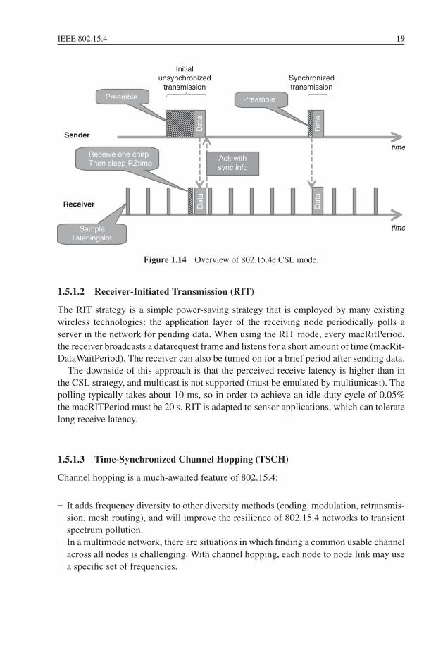
Sampled listening creates an illusion of “always on” for battery-powered nodes whilekeeping the idle consumption very low. This technology is commonly used by othertechnologies, for example, KNX-rf. The idea is that the receiver is switched on periodically(every macCSLperiod, for about 5 ms) but with a very low duty cycle. On the transmissionside, this requires senders to use preambles longer than the receiving periodicity of thetarget, in order to be certain that it will receive the preamble and keep the receiver on forthe rest of the packet transmission. For a duty cycle of 0.05% and assuming a 5-ms receiveperiod, the receive periodicity (macCSLperiod) will be 1 s, implying a receive latency ofup to 1 s per hop. CSL is the mode of choice if the receive latency needs to be in the orderof one second or less.
In 802.15.4e, CSL communication can be used between synchronized nodes (in whichcase the preamble is much shorter and simply compensates clock drifts), or betweenunsynchronized nodes in which case a long preamble is used (macCSLMaxPeriod). Thelatter case occurs mainly for the first communication between nodes and broadcast traffic:the 802.15.4e ACK contains information about the next scheduled receive time of thetarget node, so the sender can synchronize with the receiver and avoid the long preamblefor the next data packet, as illustrated in Figure 1.14.
802.15.4e CSL uses a series of microframes (“chirp packets”, a new frame type in-troduced in 15.4e) as preamble. The microframes are composed of back-to-back 15.4packets, and include a rendezvous time (RZtime) and optional channel for the actual datatransmission: receivers need to decode only one chirp packet to decide whether the comingdata frame is to their intention, and if so can decide to go back to sleep until RZtime andwake up again only to receive the data frame.
CSL supports streaming traffic: a frame-pending bit in the 15.4e header instructs thereceiver to continue listening for additional packets.
1 The value, in units of approximately approximately 0.954 μs, reports the PDU reception time measured asan offset from the scheduled start time of the current timeslot in the acknowledger’s time base.
P1: TIX/XYZ P2: ABCJWST118-c01 JWST118-Hersent November 26, 2011 17:22 Printer Name: Yet to Come
IEEE 802.15.4 19
Sender
Receiver
Initialunsynchronized
transmissionSynchronizedtransmission
Receive one chirpThen sleep RZtime
Preamble
Dat
a
Dat
aD
ata
Dat
a
time
time
Preamble
Ack withsync info
Samplelisteningslot
Figure 1.14 Overview of 802.15.4e CSL mode.
1.5.1.2 Receiver-Initiated Transmission (RIT)
The RIT strategy is a simple power-saving strategy that is employed by many existingwireless technologies: the application layer of the receiving node periodically polls aserver in the network for pending data. When using the RIT mode, every macRitPeriod,the receiver broadcasts a datarequest frame and listens for a short amount of time (macRit-DataWaitPeriod). The receiver can also be turned on for a brief period after sending data.
The downside of this approach is that the perceived receive latency is higher than inthe CSL strategy, and multicast is not supported (must be emulated by multiunicast). Thepolling typically takes about 10 ms, so in order to achieve an idle duty cycle of 0.05%the macRITPeriod must be 20 s. RIT is adapted to sensor applications, which can toleratelong receive latency.
1.5.1.3 Time-Synchronized Channel Hopping (TSCH)
Channel hopping is a much-awaited feature of 802.15.4:
– It adds frequency diversity to other diversity methods (coding, modulation, retransmis-sion, mesh routing), and will improve the resilience of 802.15.4 networks to transientspectrum pollution.
– In a multimode network, there are situations in which finding a common usable channelacross all nodes is challenging. With channel hopping, each node to node link may usea specific set of frequencies.

P1: TIX/XYZ P2: ABCJWST118-c01 JWST118-Hersent November 26, 2011 17:22 Printer Name: Yet to Come
20 The Internet of Things
Channel hopping is supported in the new ACK frame, which contains synchronizationinformation. In an uncoordinated peer to peer network, the channel hopping penalty isonly for the initial transmission, as the sender will need to continue to send “chirp packets”on a given send frequency until it becomes aligned with the receiver frequency. After thefirst ACK has been received, the sender and the receiver are synchronized and the senderwill select the sending frequency according to the channel schedule of the receiver. If alljoined nodes are in sync, then synchronizing to a single node is enough to be synchronizedto the whole network.
The time-synchronized channel hopping (TSCH) mode defined by 802.15.4e definesthe operation model of a 802.15.4e network where all nodes are synchronized. The MAClayer of 802.15.4e nodes can be configured with several “slotframes”, a collection oftimeslots repeating in time characterized by the number of time slots in the cyclicalpattern, the physical layer channel page supported, and a 27-bit channelMap indicatingwhich frequency channels in the channel page are to be used for channel hopping. Eachslotframe can be used to configure multiple “links”, each being characterized by theaddress list of neighboring devices connected to the link (or 0xfff indicating the link isbroadcasting to everyone), a slotframeId, the timeslot within the slot frame that will beused by this link, the channel offset of the link,2 the direction (receive, transmit or shared),and whether this link should be reported in advertisement frames. Each network devicemay participate in one or more slotframes simultaneously, and individual time slots arealways aligned across all slotframes.
The FFD nodes in a TSCH mode 802.15.4 network will periodically send advertisementframes that provide the following information: the PAN ID, the channel page supportedby the physical layer, the channel map, the frequency-hopping sequence ID (predefinedin the standard), the timeslot template ID3 (predefined in the standard), slotframe and linkinformation, and the absolute slot number4 of the timeslot being used for transmission ofthis advertisement frame. The advertisement frames are broadcast over all links configuredto transmit this type of frame.
For PANs supporting beacons, synchronization is performed by receiving and decodingthe beacon frames. For nonbeacon-enabled networks, the first nodes joining the networksynchronize to the PAN coordinator using advertisement frame synchronization data,then additional nodes may synchronize to existing nodes in the network by processingadvertisement frames. For networks using the time division multiple access mode, whereprecise synchronization of the whole network is essential, a new flag “clockSource” inthe FFD state supports the selection of clock sources by 802.15.4e nodes without loops.A keep-alive mechanism is introduced to maintain synchronization.
2 Logical channel selection in a link is made by taking (absolute slot number + channel offset) % number ofchannels. The logical channel is then mapped to a physical channel using predefined conventions.
3 The timeslot template defines timing parameters within each timeslot, e.g TsTxOffset=2120 μs,TsMaxPacket=4256 μs, TsRxAckDelay=800 μs, TsAckWait=400 μs, TsMaxAck=2400 μs.
4 The total number of timeslots that has elapsed since the start of the network.

P1: TIX/XYZ P2: ABCJWST118-c01 JWST118-Hersent November 26, 2011 17:22 Printer Name: Yet to Come
IEEE 802.15.4 21
1.5.2 802.15.4g
IEEE task group 802.15.4g focuses on the PHY requirements for smart utility networks(SUN).
802.15.4g defines 3 PHY modulation options:
– Multiregional frequency shift keying (MR-FSK): providing typically transmission ca-pacity up to 50 kbps. “Multiregional” means that the standard maps a given channelpage to a specific FSK modulation (2GFSK, 4GFSK . . .), frequency and bitrate. Thecurrent draft contains multiple variants for each region, implying that generic 802.15.4gradios will have to be extremely flexible.
– Multiregional orthogonal quadrature phase shift keying (O-QPSK): providing typicallytransmission capacity up to 200 kbps.
– Multiregional orthogonal frequency division multiplexing (OFDM): providing typicallytransmission capacity up to 500 kbps.
The number of frequency bands also increases to cover most regional markets:– 2400–2483.5 MHz (Worldwide): all PHYs;– 902–928 MHz (United States): all PHYs;– 863–870 MHz (Europe): all PHYs;– 950–956 MHz (Japan): all PHYs;– 779–787 MHz (China): O-QPSK and OFDM;– 1427–1518 MHz (United States, Canada): MR-FSK;– 450–470 MHz, 896–901 MHz, 901–902 MHz, 928–960 MHz (United States): MR-
FSK;– 400–430 MHz (Japan);– 470–510 MHz (China): all PHYs;– 922 MHz (Korea): MR-OFDM.
802.15.4g is particularly interesting in Europe, where 802.15.4:2006 allowed a singlechannel (868.3 MHz). 802.15.4g now offers multiple channels:
– from 863.125 to 869.725 MHz in steps of 200 kHz (MR-FSK 200 kHz);– from 863.225 to 869.625 in steps of 400 kHz (MR-FSK 400 kHz);– from 868.3 to 869.225 MHz in steps of 400 kHz(O-QPSK);– from 863.225 to 869.625 MHz in steps of 400 kHz (OFDM).
As the number of potential IEEE wireless standards and modulation options increases, thefrequency scanning time would become prohibitively long if a coordinator was to scanall possible channels using all possible modulations. To solve this problem and improvecoexistence across IEEE standards, 802.15.4g defines a new coex-beacon format, usinga standard modulation method that must be supported by all coordinators (the commonsignaling mode or CSM defined in 802.15.4g).
P1: TIX/XYZ P2: ABCJWST118-c02 JWST118-Hersent November 30, 2011 7:39 Printer Name: Yet to Come
2Powerline Communication forM2M Applications
Paul BertrandTechnology Consultant
2.1 Overview of PLC Technologies
For decades, powerline communication technologies (PLC) have made it possible to usepower lines to send and receive data. This “no-new-wire” approach makes PLC one of thebest communication technology candidates for the Smart Grid, compared to other wiredtechnologies. On the other hand, as PLC technologies use a media that was not specifiedfor communication, they have faced a number of technical challenges limiting diffusionto niche indoor markets or dedicated ultralow rate applications.
More recently, the booming of modern modulation techniques in integrated siliconmade it possible to improve both communication reliability and data rate. Combined withthe versatility of emerging protocols such as 6LoWPAN (see the 6LoWPAN chapter), amuch larger market is opening for PLC.
Instead of offering here a detailed description of the modulation techniques in use bydifferent vendors/alliances, this can be found for example in [1], this section is morefocused on the evolution and comparison of emerging technologies, in the context of thespecific requirements of M2M communication.
2.2 PLC Landscape
This section presents an overview of existing powerline technologies and standards. It isnot exhaustive and focuses on the most widespread technologies.
The Internet of Things: Key Applications and Protocols, First Edition.Olivier Hersent, David Boswarthick and Omar Elloumi.© 2012 John Wiley & Sons, Ltd. Published 2012 by John Wiley & Sons, Ltd.

P1: TIX/XYZ P2: ABCJWST118-c02 JWST118-Hersent November 30, 2011 7:39 Printer Name: Yet to Come
24 The Internet of Things
2.2.1 The Historical Period (1950–2000)
This first period was driven mainly by utilities for outdoor applications at very lowfrequencies and with an extremely low rate.
The first experiment started in 1950 for remote street lighting. Basically it wasone-way On/Off signaling of 10 kW switches at 10 Hz.
In the mid-1980s research began on the use of electrical distribution grids tosupport data transmission, in the [5–500 kHz] frequency band, always for one-waycommunication.
In 1989, the ST7536 was the first monolithic half-duplex synchronous FSK modemsuitable for applications according to EN 65 065-1 CENELEC and FCC specifications.
In 1997 the first tests for bidirectional data signal transmission over the electricaldistribution network were conducted. A specific research effort was started by Ascom(Switzerland) and Norweb (UK).
2.2.2 After Year 2000: The Maturity of PLC
In the year 2000 the tremendous development of personal computer and home networkingtriggered more and more demand for high bitrate transmission technologies. As FSKmodulation in the CENELEC band suffers strong data-rate limitations, the communicationindustry, inspired by the boom of ADSL, decided to study the implementation of OFDM(orthogonal frequency-division multiplexing) in the band above 2 MHz.
2.2.2.1 High-Rate Modulations
Homeplug and Homegrid are industrial alliances aiming to publish specifications or whitepapers on powerline technologies. Since 2000 Homeplug has issued different productsstandards allowing high data rate communication on existing home electric wires. Usually,these alliances are participating to standard organizations like IEEE and ITU.
Homeplug standards, as all high rate modulation technologies in powerline, use OFDMmodulation in the frequency band above 2 MHz.
The typical performance of Homeplug implementations is outlined below:
� HP V1.0: peak PHY rate up to 14 Mb/s.� HP AV: peak PHY rate up to 200 Mb/s.� HP AV2 compliant with IEEE 1901: peak PHY rate up to 400–600 Mb/s.� HP GreenPhy is a low-power profile of IEEE 1901 dedicated to smart grid applications
and has a peak PHY rate of 10 Mb/s.
Such impressive performance levels, over such a harsh medium as residential powerline,are only possible through usage of complex signal processing, high power level of PLC

P1: TIX/XYZ P2: ABCJWST118-c02 JWST118-Hersent November 30, 2011 7:39 Printer Name: Yet to Come
Powerline Communication for M2M Applications 25
1.0 Frame Control FEC
AV FEC Encoder
AV Frame Control FEC
Scrambler
MapperIFFT(384,3072)
CyclicPrefix,
Window& Overlap
FrameControl
Encoder
PeakLimiter
Interleaver
InsertPreamble
AFE
FrameControl
DiversityMapper
TurboConvolutional
Encoder
Product
Decoder
FECTurbo
Decoder
FrameControl
De-interleaver
384 Point
FFTAGC
TimeSync
Frame
ControlDemodulator
AFE
Demodulator Deinterleaver
TX
RX
Homeplug
1.0 FEC
AV FEC Decoder
1.0 Frame Control Decoder
De-Scrambler
3072
PointFFT
1.0 Frame Control
Data Out
AV Frame Controland PB
Data Out
Figure 2.1 HPAV OFDM Transceiver Copyright © 2005, HomePlug R© Powerline Alliance, Inc.
emissions and accordingly high power consumption. And still the effective real user datarate usually falls to less than 1/4 of the PHY maximum data rate in real-life networks.
Figure 2.1, extracted from the HPAV-White-Paper from HomePlug alliance, shows thecomplexity involved in this type of modem.
2.2.2.2 Low-Rate Modulations
Compared to high-rate OFDM modulation, the complexity of low-rate modems is muchlower and a standard DSP can, in most cases, implement the digital processing part of themodem. There are many existing technologies in this field, sometime with a very largeinstalled base.
ISO/IEC 14 908-3 (LonWorks)This international standard describes an FSK modulation in CENELEC A Band and isused for example in millions of meters in Italy. Refer to Section 4.2 for more details,including the application layer of LonWorks.

P1: TIX/XYZ P2: ABCJWST118-c02 JWST118-Hersent November 30, 2011 7:39 Printer Name: Yet to Come
26 The Internet of Things
IEC 61 334 (S-FSK)IEC 61 334 is an international standard for low-speed spread shift keying modulation onpowerline. It is also known as EN 61 334-5-1:2001. Optional upper layer parts of 61 334form the DLMS protocol used in metering applications (refer to Section 11.3 for moredetails on DLMS, including the application layer).
IEC 61 334 is the technology behind G1-PLC, deployed for example, in France asthe last-mile communication technology for ERDF (France DSO) first-generation Linkymeter.
G3-PLC and PRIME AllianceG3-PLC and PRIME are two noninteroperable powerline technologies tested by utilitiesfor metering communication. In Europe, both use the CENELEC bands to communicatebut they intend also to operate in FCC band up to 500 kHz in the US.
G3-PLC is the powerline communications specification promoted by Maxim and ERDF(French DSO implementing G3 in the second-generation deployment of its “Linky” meter)for smart grid implementations worldwide.
The main specifications of G3 are as follows:
� 10 to 490 kHz operation complies with FCC, CENELEC, and ARIB;� Coexists with IEC 61 334, IEEE 1901, and ITU G.hn systems;� Transmission on low- and medium-voltage lines (LV–LV, MV–MV, MV–LV);� OFDM modulation;� IEEE 802.15.4-based MAC layer;� 6LoWPAN adaptation layer supports IPv6 packets;� AES-128 cryptographic engine;� Adaptive tone mapping and channel estimation.
In the CENELEC A Band, used by utilities, the OFDM modulation is based on the divisionof the band into 70 tones. These tones can be modulated in either DBPSK (1 bit per tone),or DQPSK (2 bits per tone).
PRIME is an acronym (PRIME = powerline intelligent metering evolution) for anindustry alliance focused on the development of a new open, public and nonproprietarypowerline telecom solution for smart grid.
PRIME, created in May 2009, counts more than twenty members at the end of 2010.Principal members are ST Micro, Texas Instruments, ITRON, Landis & Gyr, Iberdrola,Current, ADD and ZIV.
PRIME is based on OFDM multiplexing in CENELEC-A band and is said to reach upto 100 kbps raw data rate. The OFDM signal itself uses 97 (96 data plus one pilot) equallyspaced subcarriers with a short cyclic prefix.

P1: TIX/XYZ P2: ABCJWST118-c02 JWST118-Hersent November 30, 2011 7:39 Printer Name: Yet to Come
Powerline Communication for M2M Applications 27
Differential modulation schemes are used, together with three possible constellations:DBPSK, DQPSK or D8PSK. Thus, theoretical encoded speeds of around 47 kbps, 94 kbpsand 141 kbps (if the cyclic prefix was not considered) could be obtained.
Both G3-PLC and PRIME specifications are the basis of current discussions withinIEEE P1901.2 and ITU G.hnem.
Other Low-Rate ModulationsMany other modulations are used for low-rate applications. Most of them use simplemodulations like FSK or OOK (X10 for example). Others use different models likespread spectrum or pulse modulation [3].
Table 2.1 shows a comparison between main low-rate technologies in term of standard-ization, frequency band and modulation.
2.3 Powerline Communication: A Constrained Media
Considering the advantages of powerline technology (no additional wires are required,the network already exists in every home), it is clear that this technology should alreadybe deployed in every home for all types of home-automation applications. However, thisis not the case.
We will see that reasons of this limited success are due to four key factors.
2.3.1 Powerline is a Difficult Channel
The channel mandated by CENELEC or FCC for communication is one of the noisiestexisting. In homes most appliances now switch in the zero-crossing area of the voltagesignal, creating strong spikes. Figures 2.2a and b show some examples of this noise.
Other categories of noise exist: a precise description can be found in [1].In addition to strong noise levels, the CENELEC band is also known as a strong fading
media.Figure 2.3 shows an illustration of typical fading profiles in the CENELEC A, B, C,
D bands.The notches shown in Figure 2.2 are not stable and could change apparently randomly
with time and location.
2.3.2 Regulation Limitations
By definition PLC injects high frequencies in the electric network wires. This injectionmay induce radio emissions in the HF spectrum and is likely to interfere with existingradio services. For this reason PLC emission and radiation have been regulated from thevery beginning.

P1: TIX/XYZ P2: ABCJWST118-c02 JWST118-Hersent November 30, 2011 7:39 Printer Name: Yet to Come
28 The Internet of ThingsTa
ble
2.1
Com
pari
son
ofdi
ffer
entp
ower
line
tech
nolo
gies
Org
aniz
atio
nTy
peO
rgan
izat
ion(
s)Te
chno
logy
Nam
eFr
eque
ncy
Ban
dsC
hara
cter
izat
ion
Mod
ulat
ion
Met
hods
Sign
alL
evel
Plan
Inte
rnat
iona
lSD
OIS
O/I
EC
,AN
SI,
Lon
Mar
kL
onW
orks
,IS
O/I
EC
1490
8-3,
AN
SI70
9.2
A(8
6kH
zan
d75
.453
kHz
125–
140
kHz
Fc=
131.
579
kHz
CE
NE
LE
CA
,B,C
Dua
lcar
rier
A(8
6kH
zan
d75
.453
kHz)
C(1
31.5
79kH
zan
d86
.232
kHz)
BPS
K/N
RZ
EN
5006
5-1,
FCC
Part
15
Inte
rnat
iona
lSD
OIS
O/I
EC
,BS
KN
X,I
SO/I
EC
1454
3-3-
5,E
N50
090
PL11
0(9
5–12
5kH
zFc
=11
0kH
z)PL
132
(125
–14
0kH
zFc
=13
2.5
kHz)
A(6
0,66
,72,
76,
82.0
586
kHz)
B11
0kH
z,C
132.
5kH
z
S-FS
K/N
RZ
EN
5006
5-1
Inte
rnat
iona
lSD
OIE
CT
C57
WG
09IE
C61
334-
3-1,
IEC
6133
4-5-
1,IE
C61
334-
5-2,
IEC
6133
4-4-
32
CE
NE
LE
CA
20–9
5kH
z10
kHz
tone
sepa
ratio
nsS-
FSK
EN
5006
5-1
Indu
stry
Spec
ifica
tion
PRIM
EA
llian
ce
uSys
com
,AD
D,
STM
,TI
PRIM
EC
EN
EL
EC
A(∼
42–
∼89
kHz)
,C
apab
leup
to50
0kH
z
97su
bcar
rier
s,48
8H
zsp
acin
gO
FDM
/DB
PSK
,D
QPS
K,
D8P
SK
EN
5006
5-1,
FCC
Part
15
Indu
stry
Spec
ifica
tion
Publ
icsp
ecifi
catio
n
Max
im,E
RD
F,T
IL
FN
BO
FDM
G3
PLC
35.9
–90.
6kH
z/C
EN
EL
EC
-A36
carr
iers
/C
EN
EL
EC
-AO
FDM
/DB
PSK
,D
QPS
KE
N50
065-
1,FC
CPa
rt15
Indu
stry
Spec
ifica
tion
INST
EO
NA
llian
ceIN
STE
ON
131.
65kH
zSi
ngle
carr
ier
BPS
KFC
CPa
rt15

P1: TIX/XYZ P2: ABCJWST118-c02 JWST118-Hersent November 30, 2011 7:39 Printer Name: Yet to Come
Powerline Communication for M2M Applications 29
Indu
stry
Spec
ifica
tion
Hom
ePlu
gA
llian
ceH
omeP
lug
C&
CFC
C(1
20–
400
kHz)
,C
EN
EL
EC
A,B
Spre
adSp
ectr
umFC
C12
0–40
0kH
zC
A20
–80
kHz,
CB
95–1
25kH
z
Sing
leca
rrie
r,sp
read
spec
trum
DC
SK6,
DC
SK4
EN
5006
5-1,
FCC
Part
15
Prop
riet
ary
Spec
ifica
tion
PCS
UPB
4–40
kHz
PPM
FCC
Part
15
Prop
riet
ary
Spec
ifica
tion
Pic
oE
lect
roni
csX
1012
0kH
zSi
ngle
carr
ier
OO
KFC
CPa
rt15
Prop
riet
ary
Spec
ifica
tion
AC
TA
1012
0kH
zSi
ngle
carr
ier
OO
KFC
CPa
rt15
Prop
riet
ary
Spec
ifica
tion
Phill
ips
Phill
ips
TD
A50
51A
Fcw
ithin
95–1
45kH
z(1
32.5
kHz
typi
cal)
Sing
leca
rrie
rA
SKFC
CPa
rt15
Prop
riet
ary
Spec
ifica
tion
Ari
ane
Con
trol
sPL
M-1
50–5
00kH
z,26
2kH
zex
pect
ed
Sing
leca
rrie
rFS
K/N
RZ
FCC
Part
15
Prop
riet
ary
Spec
ifica
tion
EN
EL
SIT
RE
DC
EN
EL
EC
A20
kHz–
95kH
z10
kHz
tone
sepa
ratio
nsS-
FSK
EN
5006
5-1
Prop
riet
ary
Spec
ifica
tion
Max
imG
3L
iteM
AX
2990
10–4
90kH
zC
EN
EL
EC
-FC
CA
djus
tabl
enu
mbe
rof
Subc
arri
ers
OFD
ME
N50
065-
1
Prop
riet
ary
Spec
ifica
tion
Wat
teco
WPC
1.7–
4M
Hz
LR
WB
Sfo
rlo
w-r
ate
wid
eba
ndse
rvic
es
Puls
em
odul
atio
nL
RW
BS
(Con
tinu
ed)

P1: TIX/XYZ P2: ABCJWST118-c02 JWST118-Hersent November 30, 2011 7:39 Printer Name: Yet to Come
30 The Internet of Things
Tabl
e2.
1(C
onti
nued
)
Org
aniz
atio
nTy
peO
rgan
izat
ion(
s)Te
chno
logy
Nam
eFr
eque
ncy
Ban
dsC
hara
cter
izat
ion
Mod
ulat
ion
Met
hods
Sign
alL
evel
Plan
Prop
riet
ary
Spec
ifica
tion
Yitr
an/R
ensa
sC
&C
Tur
boFC
C(1
20–
400
kHz)
CE
NE
LE
CA
,B
Spre
adSp
ectr
umFC
C12
0–40
0kH
zC
A20
–80
kHz,
CB
95–1
25kH
z
Sing
leC
arri
er,
spre
adsp
ectr
um,
DC
SKT
urbo
,D
CSK
6,D
CSK
4
EN
5006
5-1,
FCC
Part
15
Tech
nolo
gies
unde
rde
velo
pmen
t(no
deta
iled
publ
icin
form
atio
nav
aila
ble)
Inte
rnat
iona
lSD
OIE
EE
P190
1.2
LF
NB
OFD
M(D
raft
)C
EN
EL
EC
A/B
/C/D
FCC
9to
434
kHz
OFD
ME
N50
065-
1,FC
CPa
rt15
Inte
rnat
iona
lSD
OIT
U-T
SG-1
5/T
4G
.hne
m(D
raft
)C
EN
EL
EC
A/B
/C/D
FCC
9to
434
kHz
OFD
ME
N50
065-
1,FC
CPa
rt15
Inte
rnat
iona
lSD
OIS
O15
118
CE
IT
C69
ET
SIM
2M
Ele
ctri
calv
ehic
leco
mm
unic
atio
npr
otoc
olve
hicl
ean
dG
rid
CE
NE
LE
CA
/B/C
/DE
N50
065-
1
Inte
rnat
iona
lSD
OE
TSI
PLT
Low
-rat
eho
me
auto
mat
ion
1.7–
4M
Hz
LR
WB
SO
FDM
prE
N50
561-
1

P1: TIX/XYZ P2: ABCJWST118-c02 JWST118-Hersent November 30, 2011 7:39 Printer Name: Yet to Come
Powerline Communication for M2M Applications 31
10.
01
0.00
5 0
–0.0
05
-0.0
1
–0.0
15 –90
–100
–110
–120
–130
–140
0.5 0
–0.5 –1 –90
–100
–110
–120
–130
0.15
1015
2025
3035
4030
3540
45 ms
ms
FC
C N
oice
CB
Noi
se #
2
Wel
ch P
ower
Spe
ctra
l Den
sity
Est
imat
eW
elch
Pow
er S
pect
ral D
ensi
ty E
stim
ate
Freq
uenc
y (k
Hz)
7080
9010
011
012
013
0Fr
eque
ncy
(MH
z)
5055
60
0.15
0.2
0.25
0.3
0.35
0.4
0.45
0.5
Powe/frequency (dB/Hz)
Powe/frequency (dB/Hz)
Fig
ure
2.2
(a)
and
(b):
Spik
esan
dno
ise
arou
ndth
eze
ro-c
ross
ing
zone
.Cou
rtes
yY
tran
.

P1: TIX/XYZ P2: ABCJWST118-c02 JWST118-Hersent November 30, 2011 7:39 Printer Name: Yet to Come
32 The Internet of Things
0
–5
–10
–15
–20
–25
–30
–35
–400 100 KHz
Frequency200 KHz
Pow
er S
pect
rum
Mag
nitu
de (
dB)
Figure 2.3 Example of absorption in the field. Courtesy Maxim.
Basically there is a distinction in term of regulation whether PLC is narrowband orbroadband.
� Narrowband services are subject to CENELEC 50 065-1 or FCC Part15 regulations.� Broadband services regulation is still in discussion in CENELEC (prEN 50 561-1).
For narrowband services, compared to FCC Part15 in the USA, PLC regulation in Europeappears to be more restrictive as only the frequency band less than 148.5 kHz is availablefor transmission while it is open up to 500 kHz in the US.
EN 50 065-1 allocates the 3–95 kHz frequency band to utilities for metering applications(it is known as the A band) and reserves the 95–125 kHz, 125–140 kHz and 140–148.5 kHzbands (known in early versions of the standard respectively as B, C, D bands) for analogand digital application within homes, commercial or industrial premises and for controlof equipment connected to the low-voltage distribution network. Typical examples of B,C, D band applications are street lighting, electric vehicles or home automation.
As EN 50 065-1 conveys no rights to any user to communicate over any part of theelectricity network owned by another party, services using narrowband PLC in home arelimited to the 95–148.5 kHz band.
This 15-kHz-limited bandwidth severely limits services to extremely low rates appli-cations and is one of the reasons for the limited diffusion of home automation PLC inhomes in the CENELEC bands.
2.3.3 Power Consumption
Until recently, power consumption of PLC modems was not seen as a constraint due to thenatural access to energy. But the increased awareness of the overall power consumption

P1: TIX/XYZ P2: ABCJWST118-c02 JWST118-Hersent November 30, 2011 7:39 Printer Name: Yet to Come
Powerline Communication for M2M Applications 33
of IT-related technologies, has now installed power consumption as a major constraint fornew PLC technologies:
� Low power is now mandatory for many technologies including powerline systems forsmart grid and smart metering deployments.
� In Europe, the “less than 1/2 Watt” European Directive 2005/32/EC on standby powerimposes new paradigms for powerline technologies.
If we look at the numbers: the average consumption of the best IEEE 1901 200 Mb/spowerline modem is around 6 W, while it is close to 4 W for a OFDM CENELEC modem.In a home environment, 4 or 6 W are insignificant compared to a 2 kW air-conditioningunit. But, in the context of M2M with a large number of connected devices, or comparedto the consumption of a meter or replacement of a switch it is certainly prohibitive.
It is also prohibitive because the power supply size and heat dissipation are particularlychallenging in the context of the form factor required by a meter or a switch.
If we look now at the main contributing factors to the overall PLC technology powerconsumption, it appears it is roughly balanced between analog subsystems and digitalsubsystems.
According to Moore’s law, digital parts have seen astounding progress in size andperformance. But, at the end of the day, having to support increasing data rate, toughchannels, sampling frequencies and signal processing are engaged in a never-ending race,thus limiting Moore’s Law benefits regarding power consumption.
On the other hand, except for some ultralow-power coupling technologies [3], powerconsumption of couplers and analog front end (AFE) are limited in their progress by theemission level required by the injection of high-frequency signals in a difficult media.
As a consequence of restrictive regulations and slow progress in power-consumptionreduction, some companies are now working on efficient management of sleeping modesand standby states. Radio technologies, like ZigBee or 6LoWPAN, have implemented thesame strategy in the past for battery-powered nodes. At first sight, it appears to be anefficient solution for AC powered nodes too . . . but it isn’t: sleeping modes unfortunatelydo not solve the power-supply size problem. It is a common [marketing] mistake tomix up overall peak power consumption and energy. A low-energy system, expressed inwatt-hour, could need a relatively high peak power, in watt, when operating in “periodicwake-up” mode, and AC power supplies need to be dimensioned according to peak powerrequirements.
2.3.4 Lossy Network
As shown in Figure 2.4, the PLC link may be subject to as many disturbances as a wirelesslink, because every electrical device may inject noise and/or absorb the signal. Consideringthe number of electrical devices in the electrical network of a typical multidwelling

P1: TIX/XYZ P2: ABCJWST118-c02 JWST118-Hersent November 30, 2011 7:39 Printer Name: Yet to Come
34 The Internet of Things
Figure 2.4 Packet delivery ratio (PDR) variation over time on several PLC links. CourtesyWatteco.
unit and their varying electrical behavior that randomly disturbs the communicationchannel, the routing mechanism over PLC networks has to cope with very lossy links,as well as dynamic loss characteristics. Furthermore, these noise/fading generators createasymmetric links that add routing complexity.
Implementation of special purpose routing protocols is now considered as the solutionto reach full coverage with a lossy network and difficult channels. The Internet EngineeringTask Force (IETF) recognized the need to form a new Working Group to standardize anIPv6-based routing solution for IP smart object networks, which led to the formation ofa new Working Group called ROLL “Routing Over Low power and Lossy” networks in2008.
Here is the charter of ROLL:
Low-power and lossy networks (LLNs) are made up of many embedded devices with limitedpower, memory, and processing resources. They are interconnected by a variety of links, suchas (IEEE 802.15.4, Bluetooth, low-power WiFi, wired or other low power PLC (powerlinecommunication) links. LLNs are transitioning to an end-to-end IP-based solution to avoidthe problem of noninteroperable networks interconnected by protocol translation gatewaysand proxies.
The routing protocol RPL [2] developed in ROLL is the protocol chosen by ZigBeeTM
IP and 6LoWPAN. The advantage of RPL is that it is independent of the media and thenit can be the basis of interoperability between PLC and radio sensors. Interoperabilityis simply achieved by routing messages from a PLC node to a wireless node. For moredetails on RPL, refer to the Section 12.4.
Figure 2.5 shows an illustration of this dual PHY sensor network.
The conclusion is that the powerline medium appears to be a very challenging medium,limited by regulation and power consumption and until recently no existing standardreally offered a good alternative to wireless for M2M application in home. Fortunately,

P1: TIX/XYZ P2: ABCJWST118-c02 JWST118-Hersent November 30, 2011 7:39 Printer Name: Yet to Come
Powerline Communication for M2M Applications 35
IPV6 RPL BoarderRouter
PLC Node
RF Node
PLC/RF Bridge
BR BR
Bridge
Bridge
N1
N1
N2
N2
N3
N4
Figure 2.5 Wireless nodes and PLC nodes exchange messages through a RPL border router.
the recent development of ROLL and the requirement of using IPv6 open the door to newpowerline standards interoperable with wireless services using the same routing protocol.
2.3.5 Powerline is a Shared Media and Coexistence is not an OptionalFeature
2.3.5.1 Why is Coexistence So Important?
This question of coexistence in PLC has been discussed in many PLC standard orga-nizations. Many articles can be found in the Smart Grid Interoperability Panel (http://collaborate.nist.gov/twiki-sggrid/bin/view/SmartGrid/SGIP).
Powerline cables are a shared medium. They cannot provide links dedicated to a singleuser and there is no practical way to insulate two neighbors. The signals transmittedwithin an electrical network can interfere with signals generated within an adjacent houseor apartment. It is then likely that these interferences will produce data rate and qualityof service drops. The same issues exist in other share media like radio.
For this reason, it is necessary to define mechanisms to limit the harmful interferencecaused by noninteroperable neighboring devices.
Different mechanisms exist or are proposed today:
� EN 50 065-1 provides a CSMA/CA algorithm and a 132.5-kHz “channel busy” signalfor the C band.
� IEEE 1901 and ITU G9972 provide a standard called intersystem protocol (ISP) im-plementing a TDMA and frequency-division mechanism for a fair access to the sharedresource.
� Current discussions in IEEE 1901.2 are also investigating the coexistence betweenOFDM CENELEC band transmission for metering applications and legacy narrowbandservices (based on FSK modulation for example).

P1: TIX/XYZ P2: ABCJWST118-c02 JWST118-Hersent November 30, 2011 7:39 Printer Name: Yet to Come
36 The Internet of Things
� prEN50412-4 is a coexistence mechanism in the LRWBS band (2–4 MHz) proposed toCENELEC and based on CSMA/CA in subchannels)
2.3.5.2 Access to the Channel
Low-rate powerline systems have to implement access to channel mechanisms and es-pecially when there is a large number of nodes or when noninteroperable technologiesmay transmit in the same electrical network. Access to a channel is classically ruled byenergy detection in a channel coupled to a CSMA generic mechanism similar to the onedescribed in IEEE 802.15.4.
Compared to the original one, and due to the difference between radio and powerline,some timing constants are different, in particular the backoff period. Basically, the backoffperiod is the base time a node has to wait before it can transmit after sensing the channel.Compared to 802.15.4 wireless systems, a low-rate PLC modem offers higher latencyand lower data rates, however the backoff period has to be chosen short enough (1 msfor example) to allow a sufficient responsiveness for the latency requirements of home-automation applications like switching.
In order to evaluate the impact of data rate and the number of nodes versus averageaccess time, simulations have been carried out with different situations:
� Number of sensors from 5 to 30. All sensors are independent and try randomly to accessthe network.
� The number of tries/minute is presented vertically.� A maximum of fail/success rate of 3 is supposed.� There are no propagation effects and the channel is perfect (best case).
The parameters are:
� backoff period = 1 ms;� frame size varies randomly from 16 bytes to 128 bytes;� a failed transmission occurs when the total backoff time > 100 ms (typical minimum
latency for home automation HMI).
Figure 2.6 shows that the network supports 20 nodes communicating 400 ms every minute,provided the data rate is a least 100 kb/s.
With a lower data rate, on average every node will retry more than 3 times to accessthe channel.
Meters transmitting through a powerline modem in the CENELEC band might beimpacted by the results of these simulations. For example in a multidwelling situation itis likely that more than 30 nodes might be within reach of the meters. If a high activitylevel in homes is required (real-time display of the consumption, thermal regulation . . .)

P1: TIX/XYZ P2: ABCJWST118-c02 JWST118-Hersent November 30, 2011 7:39 Printer Name: Yet to Come
Powerline Communication for M2M Applications 37
Figure 2.6 Simulations of the impact of number of nodes on access time. Courtesy Watteco.
the 30 nodes could saturate the channel and the latency of the communication betweenthe meter and substations could increase.
Prioritizing meter communication and increasing data rate can minimize this effect butstill not cancel it.
Another solution is to use different frequency bands in the home and for metering. Forexample, the CENELEC band for metering and the LRWBS band (2–4 MHz) for homeautomation.
2.4 The Ideal PLC System for M2M
PLC combined with recent IPv6 developments could lead to a new standard for wiredcommunication in homes. Recently, in the context of European Mandate 441 for meteringapplications and home automation, ETSI PLT has defined the requirements of this newstandard.
What are the main requirements of this new PLC M2M standard?
� Openness and availability;� Range;� Energy consumption;� Data rate;� Robustness;� EMC regulatory compliance;

P1: TIX/XYZ P2: ABCJWST118-c02 JWST118-Hersent November 30, 2011 7:39 Printer Name: Yet to Come
38 The Internet of Things
� Coexistence with other PLC technologies;� Security;� Latency;� Interoperability with M2M wireless services.
2.4.1 Openness and Availability
Open standards, compared to proprietary developments, are accelerating factors for thedissemination and the success of any mass-market technology. Standard openness encour-ages interoperability, stimulates multisourcing and low-cost policies. The use of availablestandards, when adaptation to in-home PLC automation is possible, is a tremendousfactor of stability and interoperability between existing mature technologies and newemerging ones.
� Home automation standards must use existing, available and internationally recognizedPHY, MAC and DLL technologies. Examples are: IEEE 802.15.4, 6LoWPAN, IPv6,RPL . . .
2.4.2 Range
Range (or coverage) is one of the most important requirements in PLC. It is very chal-lenging because of the extreme harshness of the medium. multidwelling units (MDU)where multiphases networks can exceed an internode distance of 100 m are probably theworst-case situation in terms of range performance.
� The standard should be able to cover all outlets of the home. Routing protocols likeRPL can be used to ensure full coverage if needed.
2.4.3 Power Consumption
Power consumption is a very sensitive parameter for home automation applications.
� The standard must enable products to comply with local low power regulations likeDirective 2005/32/EC on energy consumption in standby mode in Europe or EnergyStar in the US.
� The standard must enable products with low power consumption in relation to thesavings users may request for energy-efficiency products.
� The power consumption of a powerline node must be comparable to the power con-sumption of a wireless node.

P1: TIX/XYZ P2: ABCJWST118-c02 JWST118-Hersent November 30, 2011 7:39 Printer Name: Yet to Come
Powerline Communication for M2M Applications 39
2.4.4 Data Rate
Data rate is not a critical requirement per se for home automation applications. A data rateof 10 kb/s is, in most cases, enough to cover in-home lighting or switching applications.However, factors like routing protocols, security, access to media mechanisms in a homewith dozen of nodes will probably increase communication stream and payload.
For that reason, it is critical not to limit the standard data rate to 10 kb/s. On the otherhand, high-rate PLC systems (>1 Mb/s) are not a good compromise for evident reasonsof power consumption. 100 kb/s appears to be a good compromise.
� The standard must provide a nominal rate of 100 kb/s in field installations.� In the case of very noisy channels, the standard should support variable data rates to
keep reliable links.
2.4.5 Robustness
The home environment can be very challenging for PLC nodes. Harsh channels in homesare due to various physical reasons:
� Low impedance appliances (from 1 ohm to 10s of ohms, pure capacitive loads, etc.);� Disturbance from common electric devices (chargers, dimmers, switching power sup-
plies, etc. . . .);� Absorption from breakers and ground fault circuit interrupter;� Electrical topology (multiphase wiring, neutral/ground connections, etc.).
In order to offer a good end-user experience:
� The standard must provide close to 100% connectivity in the home.� The standard may use routing or/and data rate adaptation in order to keep connectivity
in harsh environments.� The standard must support multiphase topologies, optionally with phase couplers.
Across the world, different home wiring topologies exist using single phase (France,Spain . . .), dual phase (US and Japan) or three phases (Germany and Northern coun-tries). Usually, the PLC signal is injected in one phase and natural crosstalk betweenphases may not always be sufficient. In that case phase couplers ensure reinjection ofsignal from one phase to the other phases.

P1: TIX/XYZ P2: ABCJWST118-c02 JWST118-Hersent November 30, 2011 7:39 Printer Name: Yet to Come
40 The Internet of Things
2.4.6 EMC Regulatory Compliance� The standard must comply with local EMC regulations in force in the frequency band
in use.
2.4.7 Coexistence� The standard must implement existing coexistence standards when using frequency
bands where other PLC systems are also transmitting.
Coexistence standards already in use by legacy PLC systems are:
– EN 50 065-1 C band: (channel busy signaling at 132.5 kHz);– ISP mechanism in the 2–30 MHz band (as described in IEEE 1901 or ITU G.9972).
2.4.8 Security� The standard must provide services to support encryption and secure data services.
However, a compromise should be found between security and cost of implementation.Furthermore, plug and play installation may conflict with strong security requirements.
� The security suite must be open and available.
2.4.9 Latency� The standard must support low-latency communication in conformance with end-user
usual expectation in home automation. Usually, a latency of 100 ms is considered as amaximum for home automation applications.
2.4.10 Interoperability with M2M Wireless Services� The standard must ensure interoperability with 6LoWPAN and other wireless compatible
protocol through gateways embedding both nodes and running RPL.
2.5 Conclusion
PLC technologies, after a rather difficult and slow start, are now on track for mainstreamdeployments triggered by smart grid and home automation investment programs andmandates all over the world.

P1: TIX/XYZ P2: ABCJWST118-c02 JWST118-Hersent November 30, 2011 7:39 Printer Name: Yet to Come
Powerline Communication for M2M Applications 41
It is worth noting that new paradigms and business models will deeply influencethe specifications of emerging standards. The capacity of the communication channelto support encrypted IPv6 frames, the large number of nodes, low power consumptionand interoperability with radio transmission technologies are clearly the next challengesengineers will have to overcome.
References
[1] PowerLine Communications (2010) Theory and Applications for Narrowband and Broadband Communi-cation Over Power Lines, Wiley
[2] RPL: IPv6 Routing Protocol for Low power and Lossy Networks - http://tools.ietf.org/html/draft-ietf-roll-rpl.
[3] IPSO White Paper #6 – “A survey of several low power Link layers for IP Smart Objects” by JP Vasseur,Paul Bertrand, Bernard Aboussouan, Eric Gnoske, Kris Pister, Roland Acra and Allen Huotori.

P1: TIX/XYZ P2: ABCJWST118-c03 JWST118-Hersent November 30, 2011 7:42 Printer Name: Yet to Come
Part TwoLegacy M2MProtocols for SensorNetworks, BuildingAutomation andHome Automation

P1: TIX/XYZ P2: ABCJWST118-c03 JWST118-Hersent November 30, 2011 7:42 Printer Name: Yet to Come
3The BACnetTM Protocol
BACnet stands for Data Communication Protocol for Building Automation and ControlNetworks. Unlike most other protocols that began as private implementations followedby standardization efforts, BACnet was built from the ground up as an independent,royalty-free, open standard control and automation protocol. The standard committeewas chaired by university professors until 2004, its goal was to harmonize data typesand formats, data exchange primitives, and common application services. Several opensource BACnet stacks are available.(e.g., http://bacsharp.sourceforge.net/; http://bacnet.sourceforge.net/.).
The scope of BACnet applications is very large, including HVAC (heating, ventilating,and air conditioning) applications, lighting control, fire control and alarm, security, andinterfacing to utility companies.
Together with LonWorks, BACnet is one of the most popular industrial automation andcontrol protocol, adopted in products of many leading vendors (Siemens Building Tech-nologies, Johnson Controls, Inc., Teletrol Systems,@IC, TAC, KMC Controls, AmericanAuto-Matrix, Contemporary Controls Ltd, Reliable Controls).
3.1 Standardization
The BACnet standardization effort began in 1987 during a Standard Project Committeemeeting of ASHRAE (American Society of Heating, Refrigerating and Air-ConditioningEngineers). BACnet became an ISO standard in 2003 (ISO 16 484-5). In Jan-uary 2006 the BACnet Manufacturers Association and the BACnet Interest Groupof North America combined their operation in a new organization called BACnetInternational (http://www.bacnetassociation.org/), which provides conformance testing
The Internet of Things: Key Applications and Protocols, First Edition.Olivier Hersent, David Boswarthick and Omar Elloumi.© 2012 John Wiley & Sons, Ltd. Published 2012 by John Wiley & Sons, Ltd.

P1: TIX/XYZ P2: ABCJWST118-c03 JWST118-Hersent November 30, 2011 7:42 Printer Name: Yet to Come
46 The Internet of Things
services (BACnet Testing Laboratories) and promotes the adoption and development ofthe standard.
3.1.1 United States
BACnet became a standard in 1995 as ASHRAE/ANSI standard 135 and a conformancetesting method was standardized in 2003 as BSR/ASHRAE Standard 135.1. The lastrevision of the standard was published in 2010.
3.1.2 Europe
BACnet was adopted in 2003 by CEN (Comite Europeen de Normalization,http://www.cen.eu) Technical Committee 247, for the management level and automa-tion level. For the Automation level, it coexists with EIBnet (Konnex), at the Field level,CEN adopted Konnex (merger of three European protocols EIB (European Installationbus), Batibus, EHS), and LonWorks/LONTalk.
Europe has a specific European user and interest group: http://www.big-eu.org.
3.1.3 Interworking
BACnet ability to interwork with other technologies has always been a key concern, andBACnet does provide enough flexibility to allow mapping of other common protocols toa BACnet model. However, there are often many ways of providing such a mapping, andthere is a need to formally specify a standard mapping in order to ensure interoperabilityof interprotocol gateway implementations:
– BACnet interoperability with Konnex (KNX) control protocol has been specified inAnnex H/5.
– BACnet interoperability with ZigBee has been specified in Annex X.
3.2 Technology
BACnet focuses on the network layer and above. At the presentation layer, it uses ASN.1syntax1 for the definition of all data structures and messages (application protocol dataunits or APDUs). The BACnet transport layer adds routing information to these APDUs,
1 ASN.1, or “Abstract Syntax Notation 1” is defined in ISO/IEC 8824. This syntax, widely used in thetelecom world, is used to define precisely data structures, and also functional primitives. It includes a standardserialization mechanism : ASN.1 BER (simple but less efficient), and ASN.1 PER (complex but extremelyefficient).

P1: TIX/XYZ P2: ABCJWST118-c03 JWST118-Hersent November 30, 2011 7:42 Printer Name: Yet to Come
The BACnetTM Protocol 47
and the resulting messages may be carried on top of virtually any link layer, using theadaptation functions provided by the BACnet network layer.
3.2.1 Physical Layer
BACnet upper layers are independent from the underlying physical layer, facilitating theimplementation of BACnet on most popular networks. BACnet physical layers have beendefined for ARCNET, Ethernet, IP tunneling (defined for routers interconnecting BACnetsegments over IP in Annex H), BACnet/IP (devices are IP aware and can communicatedirectly over IP networks), RS-232 (BACnet Point to Point), RS-485 (with BACnet specificMaster-Slave/Token Passing LAN technology, up to 32 nodes on 1200 m, at 76 kbit/s onshielded twisted pairs), and LonWorks/LonTalk.
Since 2008, there is also a standard implementation of BACnet over ZigBee R©
(Annex X).
3.2.2 Link Layer
BACnet can be implemented directly on top of the LonTalk or IEEE802.2 (Ethernet andArcNet) data link layers. It also defines a data link layer (Point to Point PTP) for RS232serial connections, and a MS/TP data link layer for RS-485.
For IP or other network technologies that can be used as link layers, the standard definesa BACnet virtual link layer (BVLL) that formalizes all the services that a BACnet devicemight require from the link layer, such as broadcasts.
For instance, BACnet devices may implement the IP BVLL, which encapsulates therequired control information not readily available from the native IP link layer (e.g., aflag indicating whether the message was received as a unicast or broadcast), in a BACnetvirtual link control information (BVLCI) header (see Figure 3.1). Thanks to the IP BVLL,BACnet devices become full-fledged BACnet IP devices, able to communicate directlyover IP without a need for an “Annex H” router. Similarly, a BACnet device couldimplement an ATM, frame relay or ISDN BVLL in order to become a native node in thesenetworks.
On many link layers, broadcasts are difficult or have their own limitations. BACnet hasa concept of a “BACnet broadcast management device” (BBMD), which implements thebroadcast requirements of BACnet for the selected link layer, for example, it may converta BACnet broadcast into IP-based multiunicast and/or broadcast messages. Devices canregister with the BBMD to receive broadcast messages dynamically.
3.2.3 Network Layer
BACnet is primarily defined as a network layer protocol, which defines the networkaddresses required for the routing of messages. BACnet networks consist of one or more

P1: TIX/XYZ P2: ABCJWST118-c03 JWST118-Hersent November 30, 2011 7:42 Printer Name: Yet to Come
48 The Internet of Things
MAC
BIP
BVLCI
NPCI
APDU
IP Hdr
UDP Hdr
Figure 3.1 Transport of a BACnet application message (APDU) over IP/UDP.
segments consisting of single physical segments or multiple physical segments connectedby repeaters. The BACnet segments are connected by bridges if they employ the sameLAN technologies, or BACnet routers otherwise.
BACnet addresses are hierarchical: the formal separation of the network identifier andthe address identifier simplifies routing. Addresses have a variable length, which makesit easy for BACnet to adapt to the native addresses of underlying link layers (Figure 3.2shows the BACnet use of an IP address). The BACnet network header (NPCI) can includethe following information elements:
– A 2-byte source network (SNet) and variable length source address (SAddr, SLen). ForEthernet, ArcNet and MS/TP, the native protocol address format is used, for LonTalk,
MAC
APDU
NPCI
Version = x‘01’
B/IP Addr
Hop count = 1
DLEN = D‘6’
DNET = D‘1’
Control = x‘24’
Figure 3.2 BACnet message from a BACnet non-IP device to a BACnet/IP device.

P1: TIX/XYZ P2: ABCJWST118-c03 JWST118-Hersent November 30, 2011 7:42 Printer Name: Yet to Come
The BACnetTM Protocol 49
the concatenation of the subnetID and nodeId (2 bytes), or the concatenation of thesubnetID and Neuron ID (7 bytes) is used.
– A 2-byte destination network (DNet) and variable-length destination address(Daddr,Dlen). For broadcast messages, DNet identifies the network on which a broad-cast is required, and Dlen=0.
– A 4-level network priority indicator– A 1-byte message type: 9 message types are used by the BACnet routing mechanisms
(e.g., Who-is-router-to-network to discover a router to a specific networkID). Vendorscan define specific extension message types.
– A 2-byte vendor ID.
Not all information elements have to be present, depending on the specific use-case: acontrol bitmask field specifies which information elements are present.
3.2.4 Transport and Session Layers
BACnet implements a collapsed OSI model in which the transport and session layers arenot required. The application layer provides the required reliability mechanisms usuallyassociated with the transport layer, as well as the segmentation and sequencing mecha-nisms usually associated with the session layer.
3.2.5 Presentation and Application Layers
BACnet does not attempt to formally separate the presentation layer and the applicationlayer (a separation that is often a bit artificial for most protocols anyway). BACnet modelsthe various features of devices as objects, exchanging service primitives. The service prim-itives are described using ASN.1 syntax and serialized using ASN.1 BER (basic encodingrules, ITU-T Recommendations X.209 and X.690, for a good introduction on ASN.1 andBACnet, see http://bacnetbill.blogspot.com/2009/10/bacnet-tagging-rules.html).
3.2.5.1 BACnet Objects
BACnet abstracts the device basic functions as objects: each device is decomposed into acollection of standardized objects, where physical inputs and outputs and other character-istics of the object (name, type, configuration parameters) are represented by properties.Each object is identified by a unique Object_Identifier within the device. See Table 3.1for a list of standard BACnet objects.
BACnet currently lists 30 object types, for which it defines standard properties and theexpected behavior:

P1: TIX/XYZ P2: ABCJWST118-c03 JWST118-Hersent November 30, 2011 7:42 Printer Name: Yet to Come
50 The Internet of Things
BACnetObjectType ::= ENUMERATED {access-door (30),accumulator (23),analog-input (0),analog-output (1),analog-value (2),averaging (18),binary-input (3),binary-ouput (4),binary-value (5),calendar (6),command (7),device (8),event-enrollment (9),event-log (25),file (10),group (11),life-safety-point (21),life-safety-zone (22),load-control (28),loop (12),multi-state-input (13),multi-state-output (14),multi-state-value (19),notification-class (15),program (16),pulse-converter (24),schedule (17),– see averaging (18),– see multi-state-value (19),structured-view (29),trend-log (20),trend-log-multiple (27),– see life-saftey-point (21),– see life-saftey-zone (22),– see accumulator (23),– see pulse-converter (24),– see event-log (25),– enumeration value 26 is reserved for a future addendum– see trend-log-multiple (27),– see load-control (28),– see structured-view (29),– see access-door (30),

P1: TIX/XYZ P2: ABCJWST118-c03 JWST118-Hersent November 30, 2011 7:42 Printer Name: Yet to Come
The BACnetTM Protocol 51
Table 3.1 Standard BACnet objects
AnalogInputAnalogOutputAnalogValueBinaryInputBinaryOutputBinaryValueCalendarCommandDeviceEventEnrolmentFileGroupLoopMultistateInputMultistateOutputNotificationClassProgramScheduleAveragingMultistateValueTrendLogLifeSafetyPointLifeSafetyZoneAccumulatorPulseConverter
� Device: all devices are required to implement the device object. The Object_Identifierof the device object must be unique across the BACnet network and is the identifier ofthe physical device implementing that device object. All other objects are implementedonly if needed. The device object lists all objects implemented by the device.
� Binary input, Binary output, Binary value.� Analog input, Analog output, Analog value, Averaging (function that monitors a
signal and records its min, max and average value).� Multistate input, Multistate output, Multistate value.� Accumulator: for devices implementing a feature that counts pulses. Pulse converter:
counts pulses or takes an accumulator object as an input, but the count can be offset(adjusted) at any time, and scaled.
� Loop: properties modeling a feedback control loop.� LifeSafetyPoint (such as smoke detectors, pull stations, sirens. . .), LifeSatefyZone
(properties associated to a group of LifeSafetyPoints and LifeSafetyZones).

P1: TIX/XYZ P2: ABCJWST118-c03 JWST118-Hersent November 30, 2011 7:42 Printer Name: Yet to Come
52 The Internet of Things
Object_Identifier Object_IdentifierObject_Name Object_NameObject_Type Object_Type
(Event Enrollment, Instance 15)
(5, 70.0, 76.0, 0.5)((Analog Input, Instance 23), Present_Value)
26
Notification Class Object
Object_Identifier
263, 3, 3(TRUE, TRUE, FALSE)
00:00, 23:59:59.99, (Device, Instance 1), 3, TRUE, (TRUE,TRUE, (TRUE))
Reference Object Event Enrollment Object
((TRUE, TRUE, TRUE, TRUE, TRUE, TRUE, TRUE,),
NOTIFICATION_CLASS“Temperature Alarms Class”(Notification Class Instance 26)
Recipient_ListAck_RequiredPriorityNotification_ClassObject_TypeObject_Name
(TRUE, TRUE, TRUE)(FALSE, FALSE, TRUE)NORMAL
ALARMOUT_OF_RANGEEVENT_ENROLLMENT“Zone 1 Temp Alarm”
Notification_ClassAcked_TransitionsEvent_EnableEvent_StateObject_Property_ReferenceEvent_ParametersNotify_TypeEvent_Type
Device_Type
Event_State
Resolution
(Analog, Input, Instance 23)“Zone 1 Temp”
FALSE50
0.1110.00.0Degrees Farenheit
NO_FAULT_DETECTEDNORMAL(FALSE, FALSE, FALSE, FALSE)“100 Ohm RTD”
ANALOG_INPUT72.3“First Floor Offices”
Max_Pres_ValueMin_Pres_ValueUnitsUpdate_IntervalOut_Of_ServiceRelibility
Status_Flags
DescriptionPresent_Value
Figure 3.3 Example use of BACnet objects for event notification (from ANSI 135 standarddocument).
� Access door: object modeling a physical door.� Calendar (list of dates). Schedule: the schedule object describes a periodic schedule
(days and time of day, with exceptions), and for each period associates time-dependentvalues to the properties of other objects.
� Event enrollment: this object defines the required conditions for an event to occur(e.g., a change of state or value, a command failure, a value getting off range for acertain duration, a sudden change of a value, etc.), and which devices or objects mustbe notified if this happens. See Figure 3.3.
� Notification Class: this list of objects that are enrolled for an event notification is usedas a property of the Event enrollment object. It also contains priority parameters. Thelist of notified elements may vary according to days of the week and time of day. SeeFigure 3.3.
� Command (a command object can be used to execute a set of actions changing propertiesof other objects).
� File: lists the properties of a file object that may be accessed using File services.� Program: list the properties modeling an application program.� Trend Log: this object models a function that logs, at periodic intervals, a given property
value. Such a log can be triggered based on predefined conditions. Trend Log MultipleObjects: same as a Trend Log, but stores multiple property values in parallel. EventLog: “FIFO” log of timestamped event notifications.
� Group: a group of objects. Structured View: organizes other objects in an org-chart-type structure.

P1: TIX/XYZ P2: ABCJWST118-c03 JWST118-Hersent November 30, 2011 7:42 Printer Name: Yet to Come
The BACnetTM Protocol 53
� Load control: this object provides the interfaces for power-load shedding, for example,processing of requests from a utility company. It support hierarchical load shedding,scheduled shedding, compliance reporting.
Typical object properties include the object name, a reliability indicator (no error detected,no sensor, etc.), the present value of a counter and its unit, a scaling factor, maximumand minimum values. They also include configuration parameters for object features, forexample, how long a value must remain out of range before reporting an error condition,or the minimal increment of a real value triggering an update notification.
3.2.5.2 BACnet Services
BACnet considers that all objects are servers that provide services. It defines 5 classes ofservices, the description of each service can be found in ANSI/ASHRAE 135 clauses 13to 17 (see Table 3.2).
Each service uses a set of messages supporting the related communication needs. Themessages are defined using ASN.1 syntax (ANSI/ASHRAE 135 clause 21) and exchangedusing standard remote operation primitives (request, indication, response, confirm):
� Alarm and event services: BACnet provides multiple event reporting options: objectsmay support “intrinsic reporting” (e.g., report an event periodically, report error con-ditions, status updates), or may be configured by means of Event enrollment object(Figure 3.3) to report specific conditions such as a change of value (COV reporting), ora value out of range. The latter mechanism, called algorithmic reporting implements asubscribe-notify model for events. The objects that requested to be notified are listed inNotification Class objects (Figure 3.3).
The following service primitives are defined for event management and reporting: Ac-knowledgeAlarm (self-explanatory), ConfirmedCOVNotification (Change of valueevent notification primitive in which receivers must report the success or failure of ac-tions taken as a result of the event), UnconfirmedCOVNotification, ConfirmedEvent-Notification, UnconfirmedEventNotification, GetAlarmSummary (BACnet eventscan be flagged as alarms, in which case a list of active alarms is returned by thisprimitive), GetEnrollmentSummary (returns a list of event-notifying objects accord-ing to specified filters, such as objects with an active event enrollment from anotherobject), GetEventInformation (returns a list of active event states within a device),LifeSafetyOperation (e.g., silence a siren), subscribeCOV (subscribe to Change ofvalue notifications for an object), SubscribeCOVProperty (subscribe to Change ofvalue notifications for a property).
� File access services: read and write primitives are atomic, that is, a single operation isexecuted at a time.

P1: TIX/XYZ P2: ABCJWST118-c03 JWST118-Hersent November 30, 2011 7:42 Printer Name: Yet to Come
54 The Internet of Things
Table 3.2 Standard BACnet services
Who IsI AmWho HasI HaveRead PropertyWrite PropertyDevice Communication ControlReinitializeDeviceAtomic Read FileAtomic Write FileTime SynchronizationUTC Time SynchronizationSubscribe COVSubscribe COV PropertyConfirmed COV NotificationUnconfirmed COV NotificationRead Property MultipleRead Property ConditionalRead RangeWrite Property MultipleGet Alarm SummaryGet Event InformationGet Enrollment SummaryAcknowledge AlarmConfirmed Event NotificationUnconfirmed Event NotificationUnconfirmed Text MessageConfirmed Text MessageAdd List ElementRemove List ElementCreate ObjectDelete ObjectUnconfirmed Private TransferConfirmed Private TransferVT OpenVT DataVT CloseLife Safety OperationGet Event Information

P1: TIX/XYZ P2: ABCJWST118-c03 JWST118-Hersent November 30, 2011 7:42 Printer Name: Yet to Come
The BACnetTM Protocol 55
� Object access services: a set of self-explanatory primitives: ReadProperty, ReadProp-ertyConditional, ReadPropertyMultiple, WriteProperty, WritePropertyMultiple,CreateObject, DeleteObject, AddListElement, RemoveListElement.
� Remote device management services: a set of primitives for maintenance purposes(start and stop BACnet message transmission, send vendor specific commands, reini-tialize a device, time synchronization). Among those primitives, the Who-Has/I-Haveservices are used to discover which devices on the network have a given object nameor object ID, the Who-Is/I-Am primitives are used to discover devices on a BACnetnetwork.
� Virtual terminal services: primitives for bidirectional exchange of character-orienteddata, “Telnet like”.
3.3 BACnet Security
BACnet device A supporting security can request a session key from a key server for afuture communication with device B. The key server will generate a session key SKaband transmit it securely to A and B (encrypted with the private keys of A, respectively B).BACnet uses 56-bit DES encryption.
Device A may then authenticate a future transaction with B: A and B authenticate eachother by exchanging challenges (based on random numbers encrypted with the sessionkey), the challenge message includes the identifier (InvokeID) of the future transaction tobe authenticated.
A may also ensure the confidentiality of the future transaction by encrypting thecorresponding application message with the session key.
3.4 BACnet Over Web Services (Annex N, Annex H6)
The XML working group of ASHRAE SSPC 135 has introduced Addendum c to BACnet-2004 that specifies a Web Services interface to building automation and control systems.The addendum is in two parts:
– Annex N to BACnet defines the BACnet Web Services interface, BACnet/WS.BACnet/WS is a connectionless protocol using a Simple Object Access Protocol 1.1interface (http://www.w3.org/2002/ws/) over HTTP (RFC 2616). The model and prim-itives exposed in Annex M are independent from the underlying protocol and couldapply to any building automation protocol (LonWorks, KNX, ModBus . . .).
– Annex H6, Combining BACnet Networks with Non-BACnet Networks, that prescribesthe gateway mapping specifically to and from BACnet messages. Annex H6 exposes aspecific profile for Web Services access to underlying BACnet objects.

P1: TIX/XYZ P2: ABCJWST118-c03 JWST118-Hersent November 30, 2011 7:42 Printer Name: Yet to Come
56 The Internet of Things
Figure 3.4 Snapshot of the SCADA engine BACnet web service.
3.4.1 The Generic WS Model
The BACnet/WS fundamental data structure is a tree of nodes under a single root node. Inorder to allow more flexibility in the tree structure, BACnet/WS has a notion of referencenode that can serve as an alias to a referent node.
Each node and each property is identified by a path:
– /Floor2/Room3/Discharge Temp identifies a node;– /Floor2/Room3/Discharge Temp:inAlarm identifies property inAlarm of node Dischar-
geTemp;– Another format commonly used by BACnet WS vendors (Figure 3.4) is the follow-
ing /[Network]/[Device]/[ObjectType]/[Instance], for instance /2/11/2/0 is a path tonetwork 2, device 11, analog value (object type 2) instance 0;
– Special value <Path>:Children indicates all the nodes one level below the current node.For instance /:Children returns all the children of the root path. /1/1/0:Children returnsall paths to Analog Inputs on Device 1.
The network visible state of each node is exposed as the node value, and a collectionof attributes (Figure 3.5). BACnet uses Primitive attributes (native XML types), Arrayattributes (arrays of Primitive values), Enumerated attributes (choice of XML stringsspecified by BACnet/WS). Only the Value attribute is writable with the services definedby the standard.
BACnet/WS defines a small set of 5 standard nodes required in any implementation,for example:10.5
.sysinfo/.software-version, a string containing the software revision of the softwarerunning on the server

P1: TIX/XYZ P2: ABCJWST118-c03 JWST118-Hersent November 30, 2011 7:42 Printer Name: Yet to Come
The BACnetTM Protocol 57
Attribute XML type Description
NodeType String Hint about a node content. One of Unknown /System
/Network /Device /Functional /Organizational /Area
/Equipment /Point /Collection /Property /other
NodeSubType String
Description String
DisplayName String
Aliases String
Reference
Attributes String Array containing the list of all attributes present in this node.
Children String Array containing the collection of identifiers for the children
of this node when accessed through this path. The path to the
each child is obtained by concatenation of the specified child
identifier with the path of the current object.
HasDynamicChildren
Boolean
Value Depends on
ValueType
e.g. if the ValueType is ‘OctetString’, the XML type of the
Value property will be base64binary.
ValueType String One of None /String /OctetString /Real /Integer /Multistate
/Boolean /Date /Time /DateTime /Duration
Units String If ValueType is ‘Real’ or ‘Integer’, Engineering unit for the
Value attribute of the node, expressed as the enumeration
identifier of the corresponding unit in the
BACnetEngineeringUnits ASN.l production (if the canonical
service option is used, otherwise arbitrary units can be used)
ValueAge Double In seconds
HasHistory Boolean
Writable Boolean True if the value is writable through web services.
WritableValues String Array containing all possible values that may be written to the
Value attribute (when ValueType is Multistate or Boolean)
InAlarm Boolean True to indicate an alarm condition
PossibleValues String Array containing all possible values of the Value attribute
(when ValueType is Multistate or Boolean)
MinimumLength nonNegativelnteger
MaximumLength nonNegativelnteger
Resolution Depends on
ValueType
Maximum Depends on
ValueType
Minimum Depends on
ValueType
Overridden Boolean
Figure 3.5 BACnet/WS mandatory and most common attributes.

P1: TIX/XYZ P2: ABCJWST118-c03 JWST118-Hersent November 30, 2011 7:42 Printer Name: Yet to Come
58 The Internet of Things
3.4.2 BACnet/WS Services
BACnet/WS defines the services used to access and manipulate the data on the server:
– getValue/getRelativeValues: from a path parameter, the getValue service retrievesa single value for a single attribute on a single node (Figure 3.6). The value can be aprimitive type or an array attribute (in which case the results are concatenated with asemicolon separation in the result string). getValues: accepts multiple paths parametersand returns multiple values. getArray/getArrayRange: these services accept a singlepath to an array parameter and return an array of strings (the entire array or a portionfor getArrayRange. getArraySize returns the size of an array.
Request
<?xm1 version="1.0" encoding="UTF-8"?>
<SOAP-ENV: Envelopexmlns:SOAP-ENV="http://schemas.xmlsoap.org/soap/envelope/"xmlns:SOAP-ENC="http://schemas.xmlsoap.org/soap/encoding/"xmlns:xsi="http://www.w3.org/2001/XMLSchema-instance"xm"lns:xsd="http://www.w3.org/2001/XMLSchema"xmlns:ns="urn:bacnet_ws">
<SOAP-ENV:Body SOAP-ENV:encodingstyle="http://schemas.xmlsoap.org/soap/encoding/">
<ns:getvalue>
<ns:optionsx/ns:options>
<ns:path>/.sysinfo/.vendor-name</ns:path>
</ns:getva"lue>
</SOAP-ENV:Body>
</SOAP-ENV:Enve1ope>
Response
<?xm1 version="1.0" encoding="UTF-8"?>
<SOAP-ENV:Envelopexmlns:SOAP-ENV="http://schemas.xmlsoap.org/soap/envelope/"xmlns:SOAP-ENC="http://schemas.xmlsoap.org/soap/encoding/"xmlns:xsi="http://www.w3.org/2001/XMLSchema-instance"xm1ns:xsd="http://www.w3.org/2001/XMLSchema"xmlns:ns="urn:bacnet_ws">
<SOAP-ENV:Body SOAP-ENV:encodingstyle="http://schemas.xmlsoap.org/soap/encoding/">
<ns:getvalueResponse>
<ns:result>SCADA Engine</ns:result>
</ns:getvalueResponse>
</SOAP-ENV:Body>
</SOAP-ENV:Enve1ope>
Figure 3.6 Example WS getValue request and response for the value of .sysinfo/.vendor-name.

P1: TIX/XYZ P2: ABCJWST118-c03 JWST118-Hersent November 30, 2011 7:42 Printer Name: Yet to Come
The BACnetTM Protocol 59
– setValue: sets a new value for a single attribute on a single node identified by a path.setValues sets multiple values identified by multiple paths.
– getHistoryPeriodic: specifies a sampling interval and a start time for a property iden-tified by its path, and returns a specified number of samples interpolated according toa specified method.
– getDefaultLocale/getsupportedLocales: retrieves the locale(s) that the server has con-figured for its default locale/supports.
Some services accept service options that modify their behavior or their return values:readback (reads back the value is the result string of setValue), errorString, errorPrefix,locale, writeSingleLocale, canonical, precision, noEmptyArrays, writePriority.
3.4.3 The Web Services Profile for BACnet Objects
This profile specifies the mapping of some BACnet object properties to BACnet/WS nodeattributes (Figure 3.7).
BACnet object property WS node attributeObject_Name DisplayNamePresent_Value ValueUnits UnitsStatus_flags[IN_alarm] InAlarmAction_Text PossibleValues/WritableValuesActive_Text, lnactive_Text PossibleValues/WritableValues
Figure 3.7 Some recommended mappings of BACnet object properties to BACnet/WS nodeattributes.
3.4.4 Future Improvements
3.4.4.1 Updated BacNet/WS Annex N: An ATOM Interface
As this book was going to press, Addendum 2010 a.m. to BACnet was about to be released.It contains a major update of the BACnet/WS interface specification. The major featuresare:
– The adoption of the ATOM Publishing protocol (defined by IETF RFC 5023) for theREST version of the interface.
– The adoption of the PubSubHubbub subscription model for data push services. Pub-SubHubbub was defined as a simple subscribe/notify extension to ATOM and RSS. Seehttp://code.google.com/p/pubsubhubbub/ for more details.
– A comprehensive XML representation of BACnet structures (Annex Q), the controlsystem modeling language (CSML).

P1: TIX/XYZ P2: ABCJWST118-c03 JWST118-Hersent November 30, 2011 7:42 Printer Name: Yet to Come
60 The Internet of Things
With this new version, BACnet/WS ceases to be a simplified interface serving limitedpurposes: it really becomes a fully functional interface that provides access to the fullfunctionality of BACnet.
3.4.4.2 Profile Names
Work is ongoing within the “Applications” (AP) working group, to investigate the de-velopment of “macro” object types suitable for various application areas. This group isstudying a proposal for a “BACnet modeling language” that is expected to provide amachine-readable way of representing the capabilities of individual BACnet devices suchas services and objects supported. A new standard object property called “Profile_Name”now allows the extension of standard (or proprietary) object types in such a way thatdevices with knowledge of the named profile are able to interpret the extended properties.This is expected to form the basis for convenient BACnet interfaces to other protocols thatsupport object-oriented representation of their functionality, for example, LonWorks.

P1: TIX/XYZ P2: ABCJWST118-c04 JWST118-Hersent November 30, 2011 7:50 Printer Name: Yet to Come
4The LonWorks R© ControlNetworking Platform
The LonWorks series of networking protocols were developed by Echelon R© Corpora-tion for the needs of control and automation applications and are now managed by theLonMark R© International trade group. The LonWorks platform was initially developed inan effort to move away from the proprietary centralized control model, where a centralcontroller receives all measurements from remote sensors and sends all commands to re-mote actuators. In an effort to eliminate the controller as a single failure point and increasethe efficiency and power of control systems, the LonWorks platform introduced a con-cept of “connection” enabling devices to exchange data directly, using a subscribe/notifymodel.
At the physical layer, the LonWorks platform is media independent; including mediatypes for copper pairs (wires) and power lines, radio, infrared light, and optical fiber.
The LonWorks platform is one of the most popular protocols for building and industrialautomation, claiming over 90 million installed devices.
4.1 Standardization
In 2008, LonWorks also was approved as ISO standards: ISO/IEC 14 908-1, -2, -3, and-4 for the protocol, twisted-pair channel, power-line channel, and IP-tunneled channel,respectively.
4.1.1 United States of America
The communication protocol (a.k.a., the LonTalk R© protocol; Echelon’s trade name)was submitted to ANSI in 1999 and accepted as a standard for control networking
The Internet of Things: Key Applications and Protocols, First Edition.Olivier Hersent, David Boswarthick and Omar Elloumi.© 2012 John Wiley & Sons, Ltd. Published 2012 by John Wiley & Sons, Ltd.

P1: TIX/XYZ P2: ABCJWST118-c04 JWST118-Hersent November 30, 2011 7:50 Printer Name: Yet to Come
62 The Internet of Things
(ANSI/CEA-709.1; originally EIA-709.1). Shortly after, the power line and twisted-pairphysical layers were accepted as part of the ANSI standard series.
4.1.2 Europe
The European Committee for Standardization (CEN) standardized the protocol for “build-ings” use in 2005. Then in 2007, the LonWorks platform became part of the ApplicationInterworking Specification (AIS) recognized by the European Committee of DomesticEquipment Manufacturers (http://www.ceced.eu/) for Household Appliances Control andMonitoring.
4.1.3 China
In China the LonWorks platform is both a national standard in the category of “controls”(GB/Z 20 177.1-2006) and in the category of “buildings” (GB/T 20 299.4-2006).
4.2 Technology
Figure 4.1 shows the structure of a LonWorks packet, including data fields used by eachprotocol layer. The protocol layers are detailed in the following sections.
BacklogPriorityAlt Path
12 Bytes
Layer 2Header
Layer 3Address Information
Layer 4Service Type
Layer 5/ 6Header
Layer 2CRC
DATA
Addr Format, Domain Length
Source Addr (Subnet/Node)
Dest Addr (Group)
Domain ID (Zero Len Domain)
Service Type IDTransaction Num
NetworkVariableSelector
2 BytesUnsigned
Long 2 Bytes
2 Bytes
1 Byte
1 Byte
1 Byte
2 Bytes
1 Byte
0 Bytes
Figure 4.1 A typical ISO/IEC 14 908-1 Packet. Reproduced by permission of © EchelonCorporation.

P1: TIX/XYZ P2: ABCJWST118-c04 JWST118-Hersent November 30, 2011 7:50 Printer Name: Yet to Come
The LonWorks R© Control Networking Platform 63
4.2.1 Physical Layer
The LonWorks protocol is media independent, and assumes only a physical layer thatcan transmit binary signals, called a channel. Specific transceivers are required for eachunderlying physical layer. The series of standards defines transceivers for twisted pair,link power, power line, radio frequency, optical fiber, coaxial cable, and infrared mediachannels (Figure 4.2, the complete list can be found at http://www.lonmark.org/spid).Most of the transceiver channels use differential Manchester encoding, where each “1”
Channel Name Media Bit rate and capacity ReferenceFO-20L/FO-20S
Fiber optic 1.25 Mbps ANSI/CEA-709.4
IP-852 LonWorks over IP Over 10000 packetsper second
ANSI/CEA-852
PL-20 (L-N)/PL-20 (L-E)
126 kHz or 140 kHzBPSK, line to neutral orline to earth
5 kbps
PL-20A CENELEC A-bandpower line (75 kHz or86 kHz BPSK)
2613 bps (about11 packets per second)
ANSI/CEA-709.2
PL-20C/PL-20N
CENELEC C-bandPower line (115 or132 kHz BPSK)with/without accessprotocol
156.3 k/3987 bps (about18 (20C) to 20 (20N)packets per second)
ANSI/CEA-709.2
TP/FT-10 Free topology twistedpair (can be branchedat any point)Max wire length : about500m (900 to 2700mwith bus termination).Devices per link : 64(when power providedby twisted pair), 128 (ifdevices have a separatedevice power source)
78.13 kbps [(about180 packets per second,peaks up to 225 packetsper second)
ANSI/CEA-709.3
TP/RS485-39 RS-485 Twisted Pair 39.06 kbps EIA/TIA-232-ETP/XF-1250 Transformer-Isolated
Twisted Pair1.25 Mbps(about576 packets per second,peaks up to 720 packetsper second)
LONMARK R©
InteroperabilityGuidelines
Figure 4.2 LonWorks media channels (most common in bold). Reproduced by permission of ©Echelon Corporation.

P1: TIX/XYZ P2: ABCJWST118-c04 JWST118-Hersent November 30, 2011 7:50 Printer Name: Yet to Come
64 The Internet of Things
Figure 4.3 A typical LonWorks data frame, least significant bits are transmitted first. Reproducedby permission of © Echelon Corporation.
is transmitted as a polarity reversal for a full period, and each “0” is represented as twopolarity reversals during a single, full period. This type of encoding ensures that there is nocontinuous component in the transmission (it averages to 0 regardless of the informationtransmitted), and that connections – particularly those using two wires – that not need tocare about polarity.
Each physical communication link may be interconnected by means of a LonWorksrouter, or extended by means of a physical layer repeater. Channels connected by a repeaterform a segment.
4.2.2 Link Layer
The protocol’s link layer provides cyclical redundancy check (CRC) error checking inorder to detect most transmission errors; an access, collision avoidance and prioritymechanism; and a data-frame format (Figure 4.3).
4.2.2.1 Access and Priority Mechanism
The media access control (MAC) algorithm employed is carrier-sense, multiple access(CSMA), in a variant called p-persistent CSMA: A LonWorks networking device isrequired to establish that the transmission medium is idle before it can start communicating(this is common to all CSMA protocols). In addition, in order to reduce the probabilityof collisions, it will begin to transmit, with probability p, in one of 1/p predefined timeslots (called beta-2 slots, during typically from 2 to 30 bit times). The number of timeslots is dynamically adjusted based on the network load: with more time slots (smallerp), the network works better during high loads, but this adds to the transmission delaycompared to fewer time slots. Each LonWorks networking packet includes the numberof acknowledgments expected as a result of sending this packet, which allows receivingdevices to estimate the upcoming network load and adjust the number of beta-2 slotsaccordingly. Adjustments are made as multiples of 16 (n×16), where n is called the

P1: TIX/XYZ P2: ABCJWST118-c04 JWST118-Hersent November 30, 2011 7:50 Printer Name: Yet to Come
The LonWorks R© Control Networking Platform 65
Figure 4.4 Details of the link layer header. Reproduced by permission of © EchelonCorporation.
current transmission-channel backlog. The required increment is indicated in the linkheader delta backlog field (Figure 4.4).
Some transceivers can send over two channels for redundancy purposes; the desiredchannel for a packet is indicated by the Path bit of the link header (Figure 4.4).
On each channel, a fixed number of the first beta-2 time slots (up to 127 time slots) canbe allocated to priority packets. Devices can send both priority packets and nonprioritypackets. The Pri bit (Figure 4.4) of the link layer header indicates whether the packet is apriority packet.
4.2.3 Network Layer
The network layer provides the message-delivery mechanisms.Each device (“node”) is identified by a unique 48-bit identifier, called the unique
node identifier (UID) or the unique_node_ID, within device memory structures. It isalso, colloquially and historically, known as the neuron ID, or neuronID. The UID doesnot change over the lifetime of the device. It is normally used only when the device isfirst inserted in the network, before it has been assigned a logical network address. Thisfacilitates the replacement of a device by a new device of the same type, which will have adifferent UID but will be assigned the same logical network address as the replaced device.The UID is also utilized for applications requiring authenticated messaging service (forhigher-security needs).
The protocol uses hierarchical addressing, and defines the domain (0, 1, 3, or 6 bytes),subnet (8 bits), and node (7 bits) subaddresses. Each device is assigned a unique nodeIDin each subnet. Therefore there may be up to 32 385 devices (255 subnets × 127 nodes)per domain. The devices of a single domain or subnet may be on various channels; anddevices from multiple domains may coexist on the same channel.
The source of each message is contained in the address field of the header, and specifiesthe sending node subnetID and GroupID (first two bytes). The target of a message maybe, depending on the header Addr field value:
� A single node: the header comprises a 2-byte destination address specifying the subnetIDand nodeID (header Addr format=2) or a 7-byte address specifying the destinationsubnetID and neuronID (header Addr format field=3).
� All devices in a subnet (3-byte address, header Addr format field=0).� All devices in a domain (3-byte address, subnetID=0, header Addr format field=0).
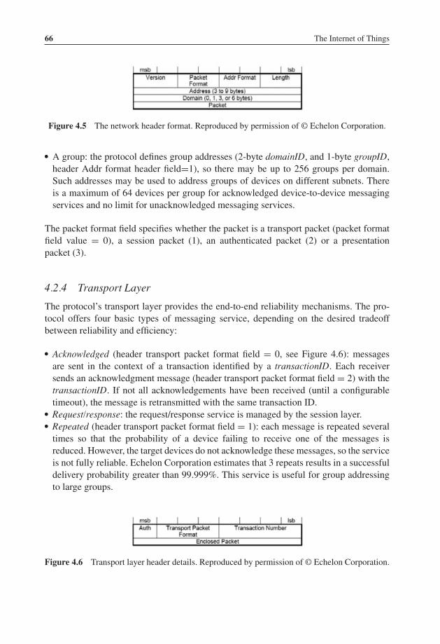
P1: TIX/XYZ P2: ABCJWST118-c04 JWST118-Hersent November 30, 2011 7:50 Printer Name: Yet to Come
66 The Internet of Things
Figure 4.5 The network header format. Reproduced by permission of © Echelon Corporation.
� A group: the protocol defines group addresses (2-byte domainID, and 1-byte groupID,header Addr format header field=1), so there may be up to 256 groups per domain.Such addresses may be used to address groups of devices on different subnets. Thereis a maximum of 64 devices per group for acknowledged device-to-device messagingservices and no limit for unacknowledged messaging services.
The packet format field specifies whether the packet is a transport packet (packet formatfield value = 0), a session packet (1), an authenticated packet (2) or a presentationpacket (3).
4.2.4 Transport Layer
The protocol’s transport layer provides the end-to-end reliability mechanisms. The pro-tocol offers four basic types of messaging service, depending on the desired tradeoffbetween reliability and efficiency:
� Acknowledged (header transport packet format field = 0, see Figure 4.6): messagesare sent in the context of a transaction identified by a transactionID. Each receiversends an acknowledgment message (header transport packet format field = 2) with thetransactionID. If not all acknowledgements have been received (until a configurabletimeout), the message is retransmitted with the same transaction ID.
� Request/response: the request/response service is managed by the session layer.� Repeated (header transport packet format field = 1): each message is repeated several
times so that the probability of a device failing to receive one of the messages isreduced. However, the target devices do not acknowledge these messages, so the serviceis not fully reliable. Echelon Corporation estimates that 3 repeats results in a successfuldelivery probability greater than 99.999%. This service is useful for group addressingto large groups.
Figure 4.6 Transport layer header details. Reproduced by permission of © Echelon Corporation.

P1: TIX/XYZ P2: ABCJWST118-c04 JWST118-Hersent November 30, 2011 7:50 Printer Name: Yet to Come
The LonWorks R© Control Networking Platform 67
Figure 4.7 The session layer header format. Reproduced by permission of © Echelon Corporation.
� Unacknowledged: the message is sent as “best effort” only and the sender is not notifiedif the message is lost en route. This service is useful for periodic data reporting fromsensors.
The device can select any of the mechanisms listed above to transport its presentationlayer messages.
For authentication to work (Auth bit in the transport header set to 1, see Figure 4.6),a 48-bit key (one per domain) must be configured in each device sending or receivingauthenticated messages. The authenticated message is sent as a normal message from Ato B but before acting on this message, B will authenticate the message by challengingA. The challenge includes a random number and A is expected to reply with a hash(encrypted encoding) of the secret domain key and the challenge. B computes the samehash locally and compares the result with the challenge response of A. If they are identical,B successfully acknowledges the original message.
4.2.5 Session Layer
The session layer replaces the transport layer when the packet format field of the net-work layer is set to 1 (Figure 4.5). It offers authentication (see transport layer) and arequest/response service.
Like the acknowledged messaging service, the request/response service is useful whena message is sent to a device or group of devices and individual responses are required fromeach receiver. The request message (session packet format=0, see Figure 4.7) may eitherbe resent until all responses (session packet format=2) have been received (the transactionnumber provides the acknowledgment mechanism), or it may be duplicated several timesto minimize the risk of packet loss. The responses from a request/response transaction,unlike the simple, low-level acknowledgment from an acknowledged messaging service,usually include application-level response data.
The enclosed packet data are formatted as a presentation-layer message.
4.2.6 Presentation Layer
4.2.6.1 Presentation-Layer Messages
The presentation layer defines the data-interpretation conventions of the protocol: it usesmessages that are transported and retransmitted by the lower layers. Except for specific
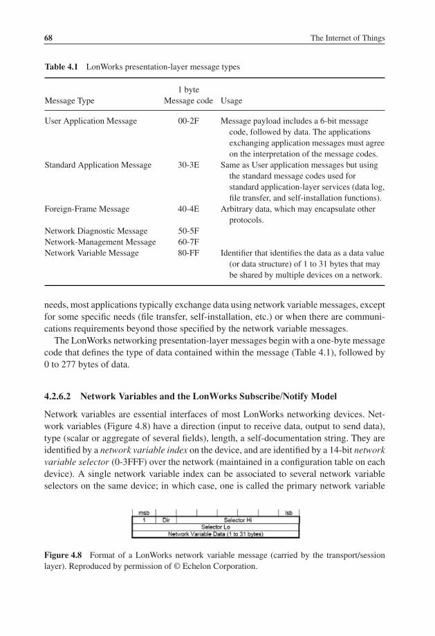
P1: TIX/XYZ P2: ABCJWST118-c04 JWST118-Hersent November 30, 2011 7:50 Printer Name: Yet to Come
68 The Internet of Things
Table 4.1 LonWorks presentation-layer message types
Message Type1 byte
Message code Usage
User Application Message 00-2F Message payload includes a 6-bit messagecode, followed by data. The applicationsexchanging application messages must agreeon the interpretation of the message codes.
Standard Application Message 30-3E Same as User application messages but usingthe standard message codes used forstandard application-layer services (data log,file transfer, and self-installation functions).
Foreign-Frame Message 40-4E Arbitrary data, which may encapsulate otherprotocols.
Network Diagnostic Message 50-5FNetwork-Management Message 60-7FNetwork Variable Message 80-FF Identifier that identifies the data as a data value
(or data structure) of 1 to 31 bytes that maybe shared by multiple devices on a network.
needs, most applications typically exchange data using network variable messages, exceptfor some specific needs (file transfer, self-installation, etc.) or when there are communi-cations requirements beyond those specified by the network variable messages.
The LonWorks networking presentation-layer messages begin with a one-byte messagecode that defines the type of data contained within the message (Table 4.1), followed by0 to 277 bytes of data.
4.2.6.2 Network Variables and the LonWorks Subscribe/Notify Model
Network variables are essential interfaces of most LonWorks networking devices. Net-work variables (Figure 4.8) have a direction (input to receive data, output to send data),type (scalar or aggregate of several fields), length, a self-documentation string. They areidentified by a network variable index on the device, and are identified by a 14-bit networkvariable selector (0-3FFF) over the network (maintained in a configuration table on eachdevice). A single network variable index can be associated to several network variableselectors on the same device; in which case, one is called the primary network variable
Figure 4.8 Format of a LonWorks network variable message (carried by the transport/sessionlayer). Reproduced by permission of © Echelon Corporation.

P1: TIX/XYZ P2: ABCJWST118-c04 JWST118-Hersent November 30, 2011 7:50 Printer Name: Yet to Come
The LonWorks R© Control Networking Platform 69
Motion Detector
Key Pad
Control Knob
0%–100%
Motion
Lamp
Brightness
Room Occupied
Alarm Bell
Key Code
Feedback
AlarmArm / Disarm
Intruder
Figure 4.9 Example of devices exchanging information through connections. Reproduced bypermission of © Echelon Corporation.
selector and the others are aliases. Network variables’ values are exchanged over thenetwork by network variable messages (Figure 4.10).
The LonWorks protocol provides two primitives to poll network variables over a net-work: one of which can poll multiple devices simultaneously using the network variableselector and one targeted to a single device using the network variable index.
The protocol also has a native subscribe/notify model – a key feature that supports theclaim that the networking platform facilitates networks designed without central points offailure. Network variables belonging to different devices can be connected if they have thesame type and length, for example, a state output (type: switch-type) of a switch device maybe connected to the switch-type input of a lamp. There are several types of connections:
– Unicast: single output to single input;– Multicast out: single output to multiple inputs on several devices;– Multicast in: multiple outputs on several devices to a single input.
Connections are created by a process called binding and are performed by a network-management tool or by the self-installation process of the device. When binding networkvariables, the protocol implementation of the device is configured with:
� The list of addresses of the other devices (or groups of devices) in the network expectingthat network variable’s value;
� The target network variable selectors.

P1: TIX/XYZ P2: ABCJWST118-c04 JWST118-Hersent November 30, 2011 7:50 Printer Name: Yet to Come
70 The Internet of Things
Figure 4.10 Example specification of a LonMark standard network-variable type (SNVT_temp_p). Reproduced by permission of © Echelon Corporation.
The application on the device will only update the network variable, and the protocolimplementation will ensure that it is sent to all configured target addresses (domain/subnet/node or group, using the appropriate network variable selector). See Figure 4.9 foran example network configuration showing several connections using network variables.
The network variable selector values 3000 to 3FFF hex are reserved for unboundnetwork variables, with the selector value equal to 3FFF hex minus the network variableindex. Selector values 0 to 2FFF hex are available for bound network variables. Thisprovides a total of 12 288 network variable selectors for bound network variables. Eachdevice can have up to 8192 network-variable aliases and 4096 of those bindable networkaliases.
Standard network variable types (SNVTs, pronounced “SNIV-its”), specify standarddata encodings (units, range, resolution, scaling, data structure, etc.) covering most

P1: TIX/XYZ P2: ABCJWST118-c04 JWST118-Hersent November 30, 2011 7:50 Printer Name: Yet to Come
The LonWorks R© Control Networking Platform 71
common usage cases. The list of SNVTs includes over 200 types and covers a widerange of applications. The complete list is available at types.lonmark.org.
If an application requires a network variable type that is not a SNVT, device manufac-turers can define custom network-variable types. These are called user network variabletypes (UNVTs).
4.2.7 Application Layer
The network configuration and network-diagnostic services are defined by the protocolstandard. The following list summarizes the standard application-layer services. Addi-tional standard application-layer services (Figure 4.11) are published at www.lonmark.org
Figure 4.11 Example specification of a LonMark functional profile: the space comfort controller –variable air-volume controller. Reproduced by permission of © Echelon Corporation.

P1: TIX/XYZ P2: ABCJWST118-c04 JWST118-Hersent November 30, 2011 7:50 Printer Name: Yet to Come
72 The Internet of Things
� Network configuration – configuration of the network attributes of a device (networkaddress and binding information for the device’s network variables).
� Network diagnostics – diagnostics commands.� File transfer – the largest practical amount of data that can be transferred in a single
packet is 228 bytes, but the LW-FTP file-transfer method transfers data using a streamof 32-byte packets.
� Application configuration – provides a standard interface to configure the behaviorof a device. The interface is based on configurable data values called configurationproperties. Standard configuration property types (SCPTs, pronounced “SKIP-its”), arethe configuration equivalent to SNVTs. An up-to-date list of SCPTs can be found attypes.lonmark.org.
� Application specification – documentation of a device’s functions as a set of func-tion blocks (a distinct set of complementary network variables and configurationproperties).
� Application diagnostics – standard testing primitives for function blocks anddevices.
� Application management – standard primitives to enable, disable, and override functionblocks on a device.
� Alarming – standard primitives for a device to report alarm conditions.
Figure 4.12 Example definition of a standard configuration-property type (SCPTminSendTime).Reproduced by permission of © Echelon Corporation.

P1: TIX/XYZ P2: ABCJWST118-c04 JWST118-Hersent November 30, 2011 7:50 Printer Name: Yet to Come
The LonWorks R© Control Networking Platform 73
� Scheduling – standard primitives for scheduling events based on time of day, day ofweek, and date.
� Time and date management – standard primitives for synchronizing the time-of-dayand date for devices within a network.
Some application-layer services are defined for device developers through a committeeof those developers within LonMark International, the trade association in support of theprotocol standards. The culmination of those application-specific functional definitionsare known as functional profiles, or simply profiles (Figure 4.11 and 4.12), and areimplemented in part or in their entirety by developers as function blocks within the device.
4.3 Web Services Interface for LonWorks Networks:Echelon SmartServer
The Echelon SmartServer is an Internet gateway and local computing platform (e.g., edgecontrol node) that connects LonWorks, ModBus, M-Bus, local I/O to other devices andnetworks, in addition to providing a SOAP Web Service-based interface for data access andconfiguration. Besides using SOAP (a W3C recommendation), the SmartServer interfaceis not formally standardized.
The SmartServer provides access to LonWorks networking devices through data points,which contain a value, data type, and format properties. The gateway implements thefollowing functions that can be used to directly access data points: DataPointRead,DataPointWrite. For each write, it is possible to specify whether the value must beimmediately propagated to the LonWorks network or not. This makes it possible to setseveral items in a structure sequentially and to propagate all values to the network at once;in an atomic way.
The SmartServer gateway also provides a set of applications accessible though SOAP(Figure 4.13).
The DataServer application can be used to create, manage, delete, and access datapoints. The Datalogger can sample and store data-point values in logs and circular buffers.The AlarmGenerator generates alarms – for instance, when certain limits of data-pointvalues are exceeded – while the AlarmNotifier logs alarm conditions, sends notificationsvia SMTP e-mail, or updates specific data points. The EventScheduler and EventCalendarapplications can be used for periodic updates of data points. The TypeTranslator can beutilized to translate values of data points with a specific variable type into a different type.
4.4 A REST Interface for LonWorks
As we have seen in the previous section, a web services interface already exists forLonWorks. However, the new trend in M2M architecture is to use a REST model, where

P1: TIX/XYZ P2: ABCJWST118-c04 JWST118-Hersent November 30, 2011 7:50 Printer Name: Yet to Come
74 The Internet of Things
DataServer Datalogger: AlarmGenerator: AlarmNotifier:
EventScheduler: EventCalendar: TypeTranslator:AnalogFB:
List List List List
List ListListList
Get Get Get Get
GetGetGetGetSet Set Set Set
SetSetSetSetDelete
Delete
Delete Delete
DeleteRuleListRuleGetRuleSetRuleDelete
DeleteDeleteDelete
ReadWriteResetPriority
ReadClear Read
WriteClear
Figure 4.13 SmartServer applications and functions. Reproduced by permission of © EchelonCorporation.
the types of interactions are restricted to only the CRUD1 verbs. This requires a specificdesign of the representation of the underlying M2M network or device.
Echelon Corporation published a first version of a REST interface for LonWorks inJuly 2010. In this version 1.0, the “LonBridge Proxy Server REST API” supports the basicCRUD REST interactions, but did not introduce yet a subscribe/notify model: this typeof interaction is feasible in a REST architecture but requires both interface sides to act asclient and server. Standardized subscribe/notify REST models have been introduced forinstance by ETSI TC M2M (refer to Chapter 14 this book): it is expected that ETSI M2Minterfaces to LonWorks will also exist in the near future, and introduce the additionalinteractions and features made possible by the ETSI TC M2M REST architecture.
4.4.1 LonBridge REST Transactions
4.4.2 Requests
The LonBridge API supports the following HTTP request methods:
� GET: retrieve resource data from the LonBridge server;� POST: create a new resource;
1 Create, read, update, delete.

P1: TIX/XYZ P2: ABCJWST118-c04 JWST118-Hersent November 30, 2011 7:50 Printer Name: Yet to Come
The LonWorks R© Control Networking Platform 75
� PUT: update an existing resource managed by the LonBridge proxy server;� DELETE: delete a resource.
The specifications for each resource describe how the commands are applied.
4.4.3 Responses
Responses include a response body and a status code.The response body may be formatted as JSON, XML, HTTP, or text. The default is
JSON. The response format may be specified as a suffix to the URL – for example GETserver/api/devices.xml returns a list of all devices in XML format. The response formatmay also be specified in the accept header.
The status code is a standard HTTP status code. Typical status codes include thefollowing:
200 – OK (standard response for successful request);
201 – Created (standard response after successfully creating a resource);
400 – Bad Request (request has invalid syntax or cannot be fulfilled);
404 – Not Found (requested resource could not be found but may be available in the future);
500 – Internal Server Error (generic error message when other messages don’t apply);
501 – Not Implemented (request not recognized).
4.4.4 LonBridge REST Resources
The various LonBridge REST resources made available by the API are regrouped inseven functional groups addressing the following domains: network, device, device type,connections, groups and measures.
4.4.4.1 Network
These resources allow to access or modify the main LonWorks network parameters.
Syntax http://server[:port]/api/network/{resource} [?params]Methods PUT, GETResources Network resources: name, domainId, domainLength, key

P1: TIX/XYZ P2: ABCJWST118-c04 JWST118-Hersent November 30, 2011 7:50 Printer Name: Yet to Come
76 The Internet of Things
4.4.4.2 Devices
Device resources are used to retrieve and update resources on an individual device or aset of devices. The device ID is the LonBridge device ID, which is the letter “o” followedby an identifier, for example: o0, o1, or o2.
Syntax http://server[:port]/api/devices[/{id}[/{resource[=value]}]][?params]Methods PUT, GET, DELETEResources Device resources: name, type, location, scene, active, and data points defined
per device type:
� blinds: angle, level, motion, scene� dimmer (Lamp Module) resources: brightness, state (on, off), power, energy,
scene� switch (Appliance Module) resources: state (on, off), power, energy, scene� occupancy: occupied� thermostat: fan (auto, on), humidity, mode (auto, heat, cool, off), schedule,
setback, setpoint, temperature, message, pricing
Device parameters: startDate (default current date; specified asday[-month[-year]] where month defaults to current month and year defaults tocurrent year), startTime (default current time; 24-h time), interval (default60 minutes), maxCount (default 100), and deviceType (default all). When astartDate or startTime parameter is specified, up to maxCount records may bereturned. Each record includes a timestamp in “year-month-dayhour:minute:second” format, for example:2010-07-05 15:43:10.
ExamplesGET server.com/api/devices – returns list of all devices. The following is an exampleXML encoded response body:
<devices>
<o0 type="switch" name="Appliance Module 1"brand="Echelon" active="true" state="on"power="27" energy="8.5913" />
<o1 type="dimmer" name="Lamp Module 1" brand="Echelon"active="true" brightness="93" state="on" power="58"energy="0.5219" />
</devices>
The following is an example JSON encoded response body:

P1: TIX/XYZ P2: ABCJWST118-c04 JWST118-Hersent November 30, 2011 7:50 Printer Name: Yet to Come
The LonWorks R© Control Networking Platform 77
{"o0": {
"type": "switch","name": "Appliance Module 1","brand": "Echelon","active": "true","state": "on","power": 27,"energy": 8.5913},
"o1": {"type": "dimmer",
"name": "Lamp Module 1","brand": "Echelon","active": "true","brightness": 93,"state": "on","power": 58,"energy": 0.5219
}}
GET server.com/api/devices?deviceType=“switch” – returns a list of all switchdevices. This corresponds to the LonBridge <get TBD /> command.
GET server.com/api/devices/o2 – returns a list of all resources defined for device o2.This corresponds to the LonBridge <o2.get/> command.
GET server.com/api/devices/o2/power – returns the last power-consumption readingfor device o2. This corresponds to the LonBridge <o2.get select=“state”/> command.
PUT server.com/api/devices/o2/state – turns on device o2 on or off (the state is sent inthe request body). This corresponds to the LonBridge <o2.set state=“on”/> command.
DELETE server.com/api/devices/o2 – deletes device o2. This corresponds to theLonBridge <o2.delete/> command.
4.4.4.3 Device Types
Lists devices by device type.
Syntax http://server[:port]/api/{deviceType}/{id}/{resource}[?params]Methods PUT, GET, DELETEResources Device resources: same as for devices.
Device parameters: same as device parameters.
4.4.4.4 Connections
Syntax http://server[:port]/api/connections/{id}/{resource}[?params]Methods PUT, GET, POST, DELETEResources Connection resources: state and setting.

P1: TIX/XYZ P2: ABCJWST118-c04 JWST118-Hersent November 30, 2011 7:50 Printer Name: Yet to Come
78 The Internet of Things
4.4.4.5 Scenes
Syntax http://server[:port]/api/scenes/{id}/{resource}[?params]Methods GET, POSTResources Scene resources: state and setting.
4.4.4.6 Groups
Syntax http://server[:port]/api/devices/{id}/groups/{id}/{resource} [?params]http://server[:port]/api/groups/{id}/{resource}[?params]
Methods PUT, GET, DELETEResources Group resources for devices: membership (true or false).
Group resources: state.
4.4.4.7 Measures
Syntax http://server[:port]/api/devices/{id}/groups/{id}/{resource} [?params]http://server[:port]/api/groups/{id}/{resource}[?params]
Methods GET, POST (define new measure), DELETE (delete measure)Resources Measure resources are used to retrieve aggregate calculations for current and
historical data.
ExamplesGET server.com/api/measures – returns list of all measures.GET server.com/api/measures/energy – returns aggregate energy usage.GET server.com/api/measures/energy?startDate=1 – returns up to 100 aggregate en-ergy usage historical values since the first of the month.GET server.com/api/measures/energy?category=lighting – returns aggregate energyusage for lighting devices.GET server.com / api / measures / energy?category = lighting&location = “LivingRoom” – returns aggregate energy usage for lighting devices in the living room location.GET server.com / api / measures / energy?category = lighting&location = “LivingRoom”&startDate=1 – returns up to 100 aggregate energy usage historical values forlighting devices in the living room location.
P1: TIX/XYZ P2: ABCJWST118-c05 JWST118-Hersent November 28, 2011 21:28 Printer Name: Yet to Come
5ModBus
5.1 Introduction
Many protocols have been designed for the needs of industrial automation and metering.These protocols generally use simple query/response models and allow for extremelysimple implementations. Many protocols derived from the frame formats defined by IEC870-5 such as:
– T101 (IEC 870-5-101) that was generated by the IEC TC57 for electric utility com-munication between master stations and remote terminal units, it is also based on theIEC-870-5-x link layer, using frame format FT 1.2.
– DNP 3.0, a protocol originally designed by Westronic, Inc. that was released into thepublic domain in 1993, based on the IEC-870-5-x link layer with a few modifications(e.g., use of FT3 frames for asynchronous, rather than synchronous, communication,inclusion of both source and destination addresses).
– M-Bus (see Section 9.3)– Profibus, a fieldbus initially designed by Siemens and later standardized as IEC 61 158
(“Digital Data Communication for Measurement and control, Fieldbus for use in in-dustrial control systems” for versions DP-V0, DP-V1 and DP-V2) and IEC 61 784(Communication Profile Family DPF3). The protocols user’s association website ishttp://www.profibus.com/.
Other protocols developed independently into de-facto standards, such as ModBus, a verycommon protocol that is used in many industrial and HVAC installations.
The Internet of Things: Key Applications and Protocols, First Edition.Olivier Hersent, David Boswarthick and Omar Elloumi.© 2012 John Wiley & Sons, Ltd. Published 2012 by John Wiley & Sons, Ltd.

P1: TIX/XYZ P2: ABCJWST118-c05 JWST118-Hersent November 28, 2011 21:28 Printer Name: Yet to Come
80 The Internet of Things
5.2 ModBus Standardization
ModBus is a trademark of Modicon inc (Schneider Electric group), which also main-tains the standard. The ModBus standard specification over a serial line can be found athttp://www.modbus.org/docs/Modbus_over_serial_line_V1_02.pdf.
ModBus is an application layer messaging protocol that provides client/server com-munication between devices connected on different types of buses or networks. Becauseof its simplicity, ModBus has become one of the de-facto standards for industrial serial-message-based communications since 1979.
ModBus typically runs on top of RS 232, RS 442 point to point or RS 485 point tomultipoint links. The ModBus/TCP specification, published in 1999 defines an IP-basedlink layer for ModBus frames.
ModBus devices communicate using a master-slave model: one device, the master, caninitiate transactions (called queries), which can address individual slaves or be broadcastto all slaves. The slaves take action as specified by the query, or return the requested datato the master.
5.3 ModBus Message Framing and Transmission Modes
The transmission mode defines the framing and bit encoding of the messages to betransmitted on the ModBus network. In a given ModBus network, all nodes must use thesame mode and serial parameters:
� In the ASCII Transmission Mode, each byte is encoded on the serial link as 2 ASCIIcharacters. Each ASCII character is sent separately as 1 start bit, 7 data bits, zero or oneparity bit, one or two stop bits. The message is framed by a starting “:” ASCII byte, andends with a “CR-LF” byte sequence (see Figure 5.1).
� In the RTU (remote terminal unit) transmission mode, the message is transmitted in acontinuous stream. Each 8-bit byte is framed by 1 start bit, 8 data bits, zero or one paritybit, one or two stop bits. The message itself starts after a silent period of at least 3.5character times.
ModBus Addresses: ModBus messages begin by the target 8-bit address that can takeany decimal value between 1 and 247. 0 is used for broadcasts. The address field of themessage frame contains two characters in ASCII mode, or 8 bits in RTU Mode. Eachquery contains the address of a specific slave. When it responds, the slave includes itsown address in the message.
ModBus Functions: The function code field contains two characters in ASCII mode,and 8 bits in RTU mode, which can take any decimal value between 1 and 255and are selected based on the device application profile. Some example functions arelisted:

P1: TIX/XYZ P2: ABCJWST118-c05 JWST118-Hersent November 28, 2011 21:28 Printer Name: Yet to Come
ModBus 81
DeviceAddress (2 bytes)
Func�on code (2 bytes)
Query Data (variable)
ErrorCheck (2 bytes)
DeviceAddress
Func�on code
Response Data
ErrorCheck
ModBusMASTER
ModBusSLAVE
Query
Response
:(0x3A)
CRLF(0x0DOA)
:(0x3A)
CRLF(0x0DOA)
Figure 5.1 ModBus message framing (ASCII mode).
� 0x02: Read Input Status. Parameters: starting register address, and number of consecu-tive addresses to read. Response data: 1 bit per input read.
� 0x11: Report Slave ID. Parameters: none. Response data: slave ID, run indicator, devicespecific data.
ModBus Data Field: The data field provides the application level information, as requiredby the ModBus function. When a given ModBus function requires variable size data, thedata field begins with the “byte count” of the data.
5.4 ModBus/TCP
The ModBus/TCP specification can be found at http://www.eecs.umich.edu/∼modbus/documents/Open_ModbusTCP_Standard.doc
ModBus/TCP provides TCP/IP access to the ModBus functionality. Each ModBusRequest/response is sent over a TCP connection established between the master and theslave, using well-known port 502. The TCP connection may be reused for several query/response exchanges.
The byte content of the ModBus request and response frames (i.e. without framing start-stop-parity bits specific to the serial physical layer) is simply transported over the TCP

P1: TIX/XYZ P2: ABCJWST118-c05 JWST118-Hersent November 28, 2011 21:28 Printer Name: Yet to Come
82 The Internet of Things
connection, in big indian order. The only addition of ModBusTCP is to add a seven-bytemessage prefix:
ref ref 00 00 00 len unit
The ref bytes are simply copied by the slave from the request, and may be used as a handleby the master. The length information in the message prefix allows proper reassembly ofthe ModBus message when it has been segmented in several IP packets. The slave addresshas been renamed “unit identifier” and is contained in unit. The rest of the messageconforms to the regular ModBus structure, but the error check fields may be omitted forobvious reasons.

P1: TIX/XYZ P2: ABCJWST118-c06 JWST118-Hersent November 26, 2011 17:31 Printer Name: Yet to Come
6KNX
6.1 The Konnex/KNX Association
The Konnex (or KNX) Association was set up in 1999 on the merger between three formerEuropean associations promoting intelligent homes and buildings:
� Batibus Club International (BCI France) promoting the Batibus system;� The European Installation Bus Association (EIBA) promoting the EIB system;� European Home Systems Association (Holland) promoting the EHS system.
The goal of the KNX Association was to define and offer certification services for the KNXopen standard, while offering legacy support and certification cervices for Batibus, EIB1
and EHS. Membership is limited to manufacturers, there are over 200 members from22 countries as of 2010, including ABB, Agilent, Bosch, Electrolux, Hager, Legrand,Merten, Moeller, Schneider, Siemens and many more leading vendors of home and build-ing automation equipment.
KNX technology is royalty free for KNX members.
6.2 Standardization
In order to standardize the specifications, the KNX association cooperates with CENELECTC 205. The KNX protocol has become an international standard in Europe as EN 50 090(media and management procedures), EN 13 321-1 (media) and EN 13 321-2 (CEN,KNXnet/IP).
1 EIB is backward compatible to KNX, most devices can be labeled both with the KNX as well as the EIBlogo.
The Internet of Things: Key Applications and Protocols, First Edition.Olivier Hersent, David Boswarthick and Omar Elloumi.© 2012 John Wiley & Sons, Ltd. Published 2012 by John Wiley & Sons, Ltd.

P1: TIX/XYZ P2: ABCJWST118-c06 JWST118-Hersent November 26, 2011 17:31 Printer Name: Yet to Come
84 The Internet of Things
At an international level, KNX is standardized by ISO and IEC (ISO/IEC 14 543-3).KNX is in prestandard stage in China as GB/Z 20 965.
There are several versions of KNX, which are all backwards compatible. The currentversion is 2.0 (since August 2009).
The overall specification counts over 6000 pages, divided into 10 volumes.2 Individualspecification documents can be purchased from the KNX association. The KonCert groupmanages KNX certification and testing.
Gateway specifications exist between BACnet (ISO 484 Annex 5 H.5 mapping KNXand BACnet, see also Chapter 3), DALI (lighting control) and KNX.
6.3 KNX Technology Overview
The overall KNX architecture is documented in Vol 3, part 3/1. The KNX architectureis decentralized: nodes can interact with other nodes without the need for a centralcontroller.
The protocol stack uses the OSI model with a null session and presentation layer. It isbased on the original work of EIB, which is therefore backward compatible to KNX.
KNX standardizes the protocol, but also the data model (EN 50 090-3-3, KNX volume3/7) for basic types (integer and float values, percentage) and common device functionssuch as switching, dimming, blinds control, HVAC and so on . . .
6.3.1 Physical Layer
The physical layer of KNX is specified in Vol 3, Chapter 3/3/1 of the specifications. KNXcan use a variety of physical layers
– TP13: Twisted pair (Chapter 3/2/2). TP was the first physical layer that was definedas part of EIB, and is still the dominant physical layer used in KNX deployments.The TP bus provides both power and communication, using inductive coupling (Figure6.2). A twisted-pair installation is made of lines, each line is composed of up to 4line segments interconnected by repeaters, and each segment interconnects up to 64devices. Lines are interconnected by line couplers (LC). The line couplers interconnectto the KNX backbone via a backbone controller (BbC), and the devices that can beaccessed via a given BbC are part of the same KNX area (or zone). Line couplers andbackbone controllers act as routers, that is, filter the messages that they relay based on
2 Vol 1 Primer (deprecated), Vol 2 Cookbook (deprecated), Vol 3 System specifications, Vol 4 Hardwarerequirements (link to relevant standards, e.g., safety and environmental requirement), Vol 5 Certificationmanual, Vol 6 profiles, Vol 7 application descriptions (actual functional profiles), Vol 8 conformance testing,Vol 9 Basic and system Components (physical couplers, bus interface modules and couplers), Vol 10 Specificstandards (Extended Tag format).
3 There was a TP0 defined, which was deprecated by KNX.

P1: TIX/XYZ P2: ABCJWST118-c06 JWST118-Hersent November 26, 2011 17:31 Printer Name: Yet to Come
KNX 85
ZONE 15
ZONE z
1.1.001
1.1.002
1.1.003
1.1.xxx
1.1.255
1.1.000
1.2.001
1.2.002
1.2.003
1.2.xxx
1.2.255
1.2.000
1.y.001
1.y.002
1.y.003
1.y.xxx
1.y.255
1.y.000
1.15.001
1.15.002
1.15.003
1.15.xxx
1.15.255
ZONE 2
1.1.001
1.1.002
1.1.003
1.1.xxx
1.1.255
1.1.000
1.2.001
1.2.002
1.2.003
1.2.xxx
1.2.255
1.2.000
1.y.001
1.y.002
1.y.003
1.y.xxx
1.y.255
1.y.000
1.15.001
1.15.002
1.15.003
1.15.xxx
1.15.255
1.15.000
ZONE 1
15.0.000
2.0.000
1.0.000
0.0.ccc
0.0.ccc
1.0.001
1.0.002
1.0.003
1.0.xxx
1.0.255
LC LC LC LC
Figure 6.1 KNX network topology.
the destination address and the domain id (when present). The address space allows upto 15 areas (Figure 6.1), each with 15 lines, and a KNX TP installation can manage amaximum of 61 249 devices.
The physical layer uses a CSMA/CA medium access control using inductive coupling(Figure 6.2), and performs error detection (horizontal or vertical parity checks withacknowledgements (Ack, Nack, busy). The bus provides a 21 to 29 V power supply,and low-power KNX nodes may draw power from the TP line (typically up to 150 mW).
KNX node
0 1
35 μS
104 μS 104 μS Power (+)
Power (–)
Communica�onTP
Figure 6.2 KNX TP node, modulation and inductive coupling.

P1: TIX/XYZ P2: ABCJWST118-c06 JWST118-Hersent November 26, 2011 17:31 Printer Name: Yet to Come
86 The Internet of Things
(*) e.r.p : effec�ve radiated powerWA : wireless audioDC : Duty cycleNB : narrow bandWB : wide band
Pow
er (m
W e
.r.p.
*)
2000
500
100
25
863.0 865.0 865.40 867.6 868.0
868.6
WA <25 mW any DC
100mw
500
mW
2 W
NB or WB, <25 mW, <1% DC
NB or WB, <10 mW, <1% DC
NB or WB, <25 mW, <0.1% DC
NB, <10 mW
NB/
WB
<0.5
W <
10%
DC
<25 mW <10%
NB/WB 5 mW 100%
Generic Short Range Devices (SRD) <10 mW <0.1% DC
868.7869.2
869.4
869.65
870.0 MHz
869.7
RFID865–868 MHz
AlarmsKNX-rfready
Figure 6.3 Usage of the 863–870 MHz band in Europe.
The transmission begins with a start bit (0), followed by a application octet, a paritybit, a stop bit (1) and a mandatory pause (11). The theoretical throughput is 9600 bps.
– PL110 Over PLC4 (Chapter 3/2/3). PL110 uses a FSK modulation scheme and wasalso part of the original EIB specification. Each PLC line can have up to 64 devices.Since PLC is inherently a broadcast open media, the separation of domains (the portionof the KNX network logical topology over which the data signals of one physical layertype propagate) is ensured by a 48-bit domain address, in addition of the zone/line/nodeId address (see TP1 for a description of these addresses).
– Over RF (Chapter 3/2/5 defined in 2001). This physical layer uses the 868-870 MHzband (Figure 6.3).
The KNX-rf 1.1 specification was updated in 2010, introducing a “push button” andeasy controller mode setup specification, and using a 1% duty cycle on the centerfrequency 868.3 MHz: this version is called “KNX-rf ready”. It allows bidirec-tional communication with low duty cycle devices by sending a 4.8-ms preamble fortransmissions. Devices are preconfigured with group addresses for multicast communi-cation, and unicast communication uses an “extended group address” composed of thegroup address of the sender and its serial number.
4 There was a PLC 132, which was removed from the specification.

P1: TIX/XYZ P2: ABCJWST118-c06 JWST118-Hersent November 26, 2011 17:31 Printer Name: Yet to Come
KNX 87
Time slot
0 1 2 3 4 5 6 7 8 9 10 11 12 13 14 15 16 17 18 19 20 21 22 23 24 25 26 27
Fast1
Fast2
Fast3
Slow1
Slow2
Figure 6.4 KNX-rf multireceiver scanning.
A further KNX-rf update is expected in 2011 called “KNX-rf multi” that introduces 3RF “fast channels” and 2 RF “slow channels” (for battery-powered devices and energy-harvesting products) as well as fast acknowledge services. Fast channel 1 would usethe existing KNX 1.1 center frequency (868.3 MHz) and a duty cycle of 1%, it is theconfiguration channel and the default call channel. Fast channel 2 would use a centerfrequency of 868.95 MHz and a duty cycle of 0-1%, Fast channel 3 (optional, coexistingwith slow channel 1) would use a center frequency of 869.85 MHz and a duty cycle upto 100%. Slow channels use a preamble length of 500 ms and duty cycle of 10%. Slowchannel 2 will use a center frequency of 869.525 MHz. KNX-rf “multi” products willnot be compatible with KNX-rf 1.1. products, but will be compatible with KNX readyproducts. Because of the preamble, a KNX-rf multireceiver can scan both fast and slowchannels (Figure 6.4).
– Over IP (Chapter 3/2/6). KNX may use IP as a native communication medium.KNXnet/IP uses binary or XML encoded PDUs to emulate bus communication. KNX/IPdefines a tunneling mechanism over IP, using datalink layer binary PDUs.
6.3.2 Data Link and Routing Layers, Addressing
The data link layer is specified in Vol 6, Chapter 3/3/2, and the routing layer is specifiedin Chapter 3/3/3.
KNX nodes exchange telegrams, formatted as in Figure 6.5. Telegrams are transmittedoctet by octet on the physical layer. Each telegram is acknowledged by the recipient nodeafter a mandatory pause (equivalent to 11 bits), and retransmitted, if needed, up to 3 times.On TP, a 9 octet command will be transmitted and acknowledged (when unicast) in about15 ms.
Each KNX node has a unique 2 byte address, used mainly for configuration purposesand as the source of telegrams. The source address is encoded on 16 bits as an areaidentifier (4 bits), a line identifier (4 bits) and a device number (8 bits). The source address
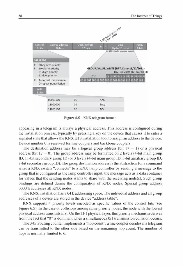
P1: TIX/XYZ P2: ABCJWST118-c06 JWST118-Hersent November 26, 2011 17:31 Printer Name: Yet to Come
88 The Internet of Things
Control8 bits
Source address16 bits
RDest. address
17 bitsL
DataUp to 16 bytes
Parity8 bits
10R1PP00
PP
00=system priority10=alarm priority01=high priority11=low priority
R 1=normal transmission0=repeat transmission
ACK8 bits
00001100 0C NAK
11000000 C0 Busy
11001100 CC ACK
r r r UUUUU r r r r UUUU r UUUUUUU
1 001 0 11 00 0 0010 11
Day (18) Month (12) Year (2011)
00 00 0 00 0 00 0 0 0000 01 00 00 00
APCI
GROUP_VALUE_WRITE (DPT_Date=18/12/2011)
(or 256 bytes for extended frames)
Figure 6.5 KNX telegram format.
appearing in a telegram is always a physical address. This address is configured duringthe installation process, typically by pressing a key on the device that causes it to enter asignaled state that allows the KNX ETS installation tool to assign an address to the device.Device number 0 is reserved for line couplers and backbone couplers.
The destination address may be a logical group address (bit 17 = 1) or a physicaladdress (bit 17 = 0). The group address may be formatted on 2 levels (4-bit main groupID, 11-bit secondary group ID) or 3 levels (4-bit main group ID, 3-bit auxiliary group ID,8-bit secondary group ID). The group destination address is the abstraction for a commandwire: a KNX switch “connects” to a KNX lamp controller by sending a message to thegroup that is configured as the lamp controller input, the message acts as a data containerfor values that the sending nodes wants to share with the receiving node(s). Such groupbindings are defined during the configuration of KNX nodes. Special group address0000 h addresses all KNX nodes.
The KNX installation has a 64 k addressing space. The individual address and all groupaddresses of a device are stored in the device “address table”.
KNX supports 4 priority levels encoded as specific values of the control bits (seeFigure 6.5). In the case of collisions among same priority nodes, the node with the lowestphysical address transmits first. On the TP1 physical layer, this priority mechanism derivesfrom the fact that “0” is dominant when a simultaneous 0/1 transmission collision occurs.
The 3-bit routing counter implements a “hop count”: a line coupler decides if a telegramcan be transmitted to the other side based on the remaining hop count. The number ofhops is normally limited to 6.

P1: TIX/XYZ P2: ABCJWST118-c06 JWST118-Hersent November 26, 2011 17:31 Printer Name: Yet to Come
KNX 89
An 8-bit parity field secures the KNX telegram, it is based on a vertical parity scheme:bit i of the security field is set to 1 if the octet-wise sum of bits i of the previous telegramdata is an even number.
6.3.3 Transport Layer
The KNX transport layer is specified in Volume 3, Chapter 3/4.The transport layer (TL) provides a connection-oriented peer to peer communication
service, providing a connect and disconnect primitive, a TL-acknowledgment, sequencecounter and time-out management (typically 6 s for the configuration mode).
The transport layer also removes the source of the message before calling the applicationlayer, and therefore the behavior of actuators never depends on the source of messages.
6.3.4 Application Layer
The KNX application layer is defined in Vol 3, Section 3/3/7. The application layerdefines the group objects, and the exchange of group-object values via service requests,for instance “group value write” illustrated in Figure 6.5.
The application layer also defines the “property value write” service, which is used toset values and configuration parameters to KNX device interface objects.
6.3.5 KNX Devices, Functional Blocks and Interworking
Volume 3, part 7 is dedicated to interworking. The overall interworking model is outlinedin 3/7/1. Chapter 3/4 defines the application environment, and Chapter 3/4/1 definesthe application interface layer, including data representation models for group objectsand interface objects. Such as data structures or flags (e.g., transmission allowed, writeallowed, data has been written by the bus . . .).
KNX devices are defined by the functional blocks that they support. A functional blockis a logical grouping of inputs, outputs and parameters that are useful to perform a certainfunction. For instance the “sunblind actuator basic” is one of the functional blocks definedby KNX, which specifies:
– A list of mandatory and optional inputs (Move UpDown, StopStep UpDown, Set Ab-solute Position blinds Percentage, WindAlarm . . .).
– A list of mandatory and optional outputs (Info Move UpDown, Current AbsolutePosition Blinds Length, . . .).
– A list of mandatory and optional parameters (Reversion Pause time, Move Up/Downtime, Preset Slat angle, . . .).
Inputs, outputs and parameters are specified by their datapoint types (see Section 6.3.5.3,and a specific functional interpretation of the Datapoint values in the specific context of

P1: TIX/XYZ P2: ABCJWST118-c06 JWST118-Hersent November 26, 2011 17:31 Printer Name: Yet to Come
90 The Internet of Things
the functional block. Inputs, outputs and parameters may be published as properties orgroup objects.
KNX volume 6 provides an extensive library of functional blocks (over 146 as of 2011)such as dimming controllers, room temperature controllers, schedulers, system clock,alarm, and so on.
6.3.5.1 Group Objects
The process information of KNX functional blocks (input, output or parameter) may bepublished as a group object (GO). A group object may be read or written over the bus viadedicated multicast service primitives. The KNX specification of each functional blockdefines which of the inputs, outputs and parameters may, or must, be published as a groupobject.
The type of the group object is described by a datapoint (see Section 6.3.6.). A groupobject that sends its value may be configured with one and only one destination groupaddress, but a group object may listen to several group addresses. The target and monitoredgroup addresses are configured in the KNX device Address Table. All group objects linkedto the same group address must be of the same datapoint.
For example, if the on/off group object of a presence sensor (an output) is assignedgroup address 1/1, and the on/off group object of a light controller (an input) is alsoassigned group address 1/1, then the presence sensor will control the light controller.
6.3.5.2 Interface Objects
Interface objects (IO) store certain properties of the device, mostly parameters (Figure 6.6).A node can have up to 256 interface objects. The type of each interface object is identified
IO (id=01)
Prop. (id=01)
KNX device
Prop. (id=02)
Prop. (id=03)
Prop. (id=04)
IO (id=02)
Prop. (id=01)
Prop. (id=02)
Prop. (id=03)
Prop. (id=04)
Figure 6.6 KNX interface objects and properties.
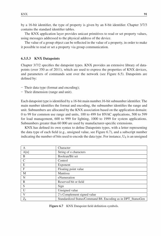
P1: TIX/XYZ P2: ABCJWST118-c06 JWST118-Hersent November 26, 2011 17:31 Printer Name: Yet to Come
KNX 91
by a 16-bit identifier, the type of property is given by an 8-bit identifier. Chapter 3/7/3contains the standard identifier tables.
The KNX application layer provides unicast primitives to read or set property values,using messages addressed to the physical address of the device.
The value of a group object can be reflected in the value of a property, in order to makeit possible to read or set a property via group communication.
6.3.5.3 KNX Datapoints
Chapter 3/7/2 specifies the datapoint types. KNX provides an extensive library of data-points (over 350 as of 2011), which are used to express the properties of KNX devices,and parameters of commands sent over the network (see Figure 6.5). Datapoints aredefined by:
– Their data type (format and encoding);– Their dimension (range and unit).
Each datapoint type is identified by a 16-bit main number.16-bit subnumber identifier. Themain number identifies the format and encoding, the subnumber identifies the range andunit. Subnumbers are allocated by the KNX association based on the application domain:0 to 99 for common use range and units, 100 to 499 for HVAC applications, 500 to 599for load management, 600 to 999 for lighting, 1000 to 1999 for system applications.Subnumbers greater than 60 000 are used by manufacturer-specific extensions.
KNX has defined its own syntax to define Datapoints types, with a letter representingthe data type of each field (e.g., unsigned value, see Figure 6.7), and a subscript numberindicating the number of bits used to encode the data type. For instance, U8 is an unsigned
A CharacterA[n] String of n charactersB Boolean/Bit setC ControlE ExponentF Floating point valueM MantissaN eNumerationR Reserved bit or fieldS SignU Unsigned valueV 2’s Complement signed valueZ8 Standardized Status/Command B8. Encoding as in DPT_StatusGen
Figure 6.7 KNX Datapoint field definition symbols.

P1: TIX/XYZ P2: ABCJWST118-c06 JWST118-Hersent November 26, 2011 17:31 Printer Name: Yet to Come
92 The Internet of Things
r r r U U U U U r r r r U U U U r U U U U U U U
1 0 0 1 0 1 1 0 0 0 0 0 1 0 1 1
Day (18) Month (12) Year (2011)
Figure 6.8 DPT_Date KNX datapoint.
number field encoded over 8 bits. DPT_Date is encoded as r3N5r4N4r1U7, and illustratedon Figure 6.8.
For metering applications, KNX has defined a number of datapoints aimed at tunnelingM-Bus addresses and metering values, in order to facilitate interworking. See Section 9.3for more details.
The library of datapoint types may be downloaded from the KNX Association’s websitefor free.
Type information is used mainly at configuration time: it is not transmitted for betterperformance and to avoid imposing unnecessary restrictions on the combinations ofdevices.
6.4 Device Configuration
Device configuration uses mainly point to point (unicast) telegrams. There are threeoptions to configure a node:
– In the system mode or “S-mode”, the management configuration tool runs on a PC(using KNX ETSTM software, which stores configuration data as XML schema).
– In easy mode or “E-mode”, several strategies are employed to avoid the use of a PCto configure the network. An embedded “master controller” may be activated to searchpartner devices, and connects to further devices one by one (identify/discover device).Group bindings may then be configured via a controller menu, or in “push button”mode. In the “push button” mode, links are configured one by one by first activatingthe actuator (“push-button”), then the sensor to be enrolled.
– Devices may also be preconfigured using a logical tag (extended possibility specifiedin Volume 10). The devices are preconfigured and use a specific framing format (EFFextended frame format), in additional of the standard format. This mode introducessemantical and geographical zoning tags. Configuration tuning is performed with ETS.
P1: TIX/XYZ P2: ABCJWST118-c07 JWST118-Hersent November 30, 2011 7:53 Printer Name: Yet to Come
7ZigBee
7.1 Development of the Standard
The 802.15.4 standard provides a physical and link layer technology optimized for lowbitrate, low duty cycle applications. However, in practice sensor and control applicationsalso need a mesh networking layer, and a standard syntax for application layer messages.In 2002, several companies decided to form the ZigBee alliance to build the missingstandard layers that would be required to enable a multivendor mesh network on top of802.15.4 radio links.
In 2008, the ZigBee alliance counted more than 200 members:
� Promoter members get early access to, contribute to and vote on the specifications ofthe alliance. They can veto decisions made by other participants in the alliance and getspecial marketing exposure in ZigBee events. New candidates for the promoter statusmust get co-opted by existing promoter members.
� Participant members have the same contribution and voting rights as promoters, butwithout veto rights.
� Adopters also get early access at the specifications, but can contribute only to theapplication profile working groups, and do not have voting rights.
The ZigBee alliance regularly organizes interop events, called ZigFests, and organize adevelopers conference twice a year. In order to ensure interoperability across vendors, theuse of the ZigBee Compliant Platform (ZCP) certification and logo is reserved for productspassing the ZigBee test suite, which includes interoperability tests with the “Golden units”(stacks from four reference implementations: Freescale, Texas Instruments, Ember, andIntegration).
The deployment of many telecom standards either failed or was slowed down bymultiple patent claims, many of which were not disclosed during the design phase of the
The Internet of Things: Key Applications and Protocols, First Edition.Olivier Hersent, David Boswarthick and Omar Elloumi.© 2012 John Wiley & Sons, Ltd. Published 2012 by John Wiley & Sons, Ltd.
P1: TIX/XYZ P2: ABCJWST118-c07 JWST118-Hersent November 30, 2011 7:53 Printer Name: Yet to Come
94 The Internet of Things
standard. While the ZigBee alliance can do nothing against potential patent claims comingfrom nonmembers, it did verify that no technology included in the standard was subjectof a known patent. In addition, every new member of the ZigBee alliance must sign adisclosure statement regarding patents that could potentially apply to ZigBee technology.
There are several versions of ZigBee. The current versions of ZigBee are ZigBee2006/2007 (stack profile 0x01, ZigBee 2007 adds optional frequency agility and fragmen-tation), and ZigBee Pro (stack profile 0x02) that adds support for more nodes and morehops through source routing (it does not support tree routing), multicasting, symmetriclinks and a high security level. There was a ZigBee 2004 version, which is now deprecated.
7.2 ZigBee Architecture
7.2.1 ZigBee and 802.15.4
ZigBee sits on top of 802.15.4 physical (PHY) and medium-access control (MAC) layers,which provide the functionality of the OSI physical and link layers.
So far ZigBee uses only the 2003 version of 802.15.4. All existing ZigBee commercialdevices use the 2.4 GHz S-Band as the 2003 version of 802.15.4 does not allow sufficientbandwidth on other frequencies. The 2006 version adds improved data-transfer rates for868 MHz and 900 MHz but is not yet part of the ZigBee specification.
802.15.4 offers 16 channels on the 2.4 GHz, numbered 11 to 26. ZigBee uses only thenonbeacon-enabled mode of 802.15.4, therefore all nodes use CSMA/CA to access thenetwork, and there is no option to reserve bandwidth or to access the network determinis-tically. ZigBee restricts PAN IDs to the 0x0000 – 0x3FFF range, a subset of the 802.15.4PAN ID range (0x0000-0xFFFE).
All unicast ZigBee commands request a hop by hop acknowledge (optional in 802.15.4),except for broadcast messages.
7.2.2 ZigBee Protocol Layers
The ZigBee network layer provides the functionality of the OSI network layer, adding themissing mesh routing protocol to 802.15.4. It also encapsulates the network formationprimitives of the 802.15.4 MAC layer (network forming and joining).
The rest of the ZigBee protocol layers (Figure 7.1) do not follow the OSI model:
– The Application Support Sublayer (APS) layer has several functions:• Multiplexing/demultiplexing: it forwards the network layer messages to the appropri-
ate application objects, according to their endpoint ID (each application is allocatedan endpoint ID).
• Binding: the APS layer maintains the local binding table, that is, records remote nodesand endpoints which have registered to receive messages from a local endpoint.
• 64-bit IEEE to 16-bit ZigBee network node address mapping.

P1: TIX/XYZ P2: ABCJWST118-c07 JWST118-Hersent November 30, 2011 7:53 Printer Name: Yet to Come
ZigBee 95
Figure 7.1 ZigBee architecture overview.
• Management of end to end acknowledgements. The application layer supports ac-knowledgements independently of the link layer acknowledgements of 802.14.4.The APS manages retries and duplicate filtering as required, simplifying applicationprogramming.
• Fragmentation.
Also, as part of the application support sublayer management entity, or APSME:
• Group addressing: the APSME allows to configure the group membership tables ofeach endpoint ID, and forwards messages addressed to a group ID to the applicationobjects with relevant endpoint IDs.
• Security: management of keys.– The ZigBee Device Object (ZDO) layer is a specific application running on endpoint 0,
designed to manage the state of the ZigBee node. The ZDO application implements theinterfaces defined by the ZigBee device profile (ZDP, application profile ID 0x0000).These primitives encapsulate the 802.15.4 network formation primitives of the Zig-Bee network layer (node discovery, network joining), as well as additional primitivessupporting the concept of binding (see Section 7.5.2.2).
– The ZigBee Cluster Library (ZCL) was a late addition to ZigBee, specified in aseparate document. It consists in a library of interface specifications (cluster commandsand attributes) that can be used in public and private application profiles. It is now

P1: TIX/XYZ P2: ABCJWST118-c07 JWST118-Hersent November 30, 2011 7:53 Printer Name: Yet to Come
96 The Internet of Things
considered as one of the key assets of ZigBee: while the ongoing evolution ofZigBee towards a 6LoWPAN-based networking layer is likely to replace the originalnetworking layers of ZigBee, the ZCL is likely to remain the “lingua franca” ofapplication developers. One important addition of the ZCL is the group cluster, whichprovides the network interface for group formation and management.
– The Application Framework layer provides the API environment of ZigBee applica-tion developers, and is specific of each ZigBee stack. Each application is assigned anEndpoint ID.
The interfaces of ZigBee layers are called “service access points” (SAP), as in 802.15.4.One interface, the layer management entity ([layer name]-ME) is responsible for con-figuring internal data of the layer. Another interface, the data entity ([layer name]-DE),provides the data send/receive and other nonmanagement primitives.
7.2.3 ZigBee Node Types
The ZigBee node types listed below are not mutually exclusive. A given device couldimplement some application locally (e.g., a ZigBee power plug) acting as a ZigBee EndDevice, and also be a ZigBee router and even a ZigBee coordinator.
– ZigBee End-Device (ZED): this node type corresponds to the 802.15.4 reduced func-tion device. It is a node with a low duty cycle (i.e. usually in a sleep state and notpermanently listening), designed for battery operation. ZEDs must join a networkthrough a router node, which is their parent.
– ZigBee router (ZR): this node type corresponds to the 802.15.4 full function device(FFD). ZigBee routers are permanently listening devices that act as packet routers, oncethey have joined an existing ZigBee network.
– ZigBee Coordinator (ZC): this node type corresponds to a 802.15.4 full functiondevice (FFD) having a capability to form a network and become a 802.15.4 PANcoordinator. ZigBee coordinators can form a network, or join an existing network(in which case they become simple ZigBee routers). In nonbeacon-enabled 802.15.4networks, coordinators are permanently listening devices that act as routers, and sendbeacons only when requested by a broadcast beacon request command.
The ZigBee coordinator also contains the trust center, which is responsible for admissionof new nodes on the network and management of security keys (see Section 7.7).
7.3 Association
7.3.1 Forming a Network
When forming a network, a ZigBee coordinator first performs an active scan (it sendsbeacon requests) on all channels defined in its configuration files. It then selects the

P1: TIX/XYZ P2: ABCJWST118-c07 JWST118-Hersent November 30, 2011 7:53 Printer Name: Yet to Come
ZigBee 97
channels with the fewer networks, and if there is a tie performs a passive scan to determinethe quietest channel. It finally broadcasts a 802.15.4 beacon for the selected PAN ID on theselected radio channel, then remains silent (or repeats the beacon periodically, dependingon the implementation). Depending on the configuration of the stack, the scan duration oneach channel can range from 31 ms to several minutes, so the network-forming processcan take significant time. If there are any ZigBee routers associated to the network, theywill typically repeat the beacon with an offset in time relative to their parent’s beacon (anextension of 802.15.4:2003).
The ZigBee specification allocates range 0x0000 to 0x3FFF for PAN IDs (a subset of therange defined by 802.15.4: 0x0000 to 0xFFFE). The PAN-ID should be unique for a givenchannel for networks not capable of dynamic channel change (ZigBee 2006), and uniqueon all channels if channel agility is enabled (ZigBee 2007, ZigBee PRO). A ZigBee coordi-nator beacon may also include an extended PAN ID (64 bit EPID), in addition of the 16-bit802.15.4 PAN identifier, in order to facilitate vendor specific network selection for joiningnodes. This EPID identifier is only used in the beacon frames and has no other uses, whilethe 16-bit 802.15.4 PAN identifier is always used for joining and addressing purposes.
7.3.2 Joining a Parent Node in a Network Using 802.15.4 Association
ZigBee devices that are not yet associated either capture by chance the beacon, or tryto locate a network by broadcasting a 802.15.4 beacon request on each of the 16 radiochannels (active scan, see Figure 7.2), unless the radio channel has been preconfiguredor determined in the application profile. If a coordinator has formed a network on oneof those channels, it responds to the beacon request by broadcasting a 802.15.4 beacon,which specifies the 16-bit PAN ID of the network, the address of the coordinator in short16-bit format or extended 64-bit format, and optionally an extended PAN ID (EPID). AnyZigBee router that has already joined the network will also respond with a beacon if theyhear the beacon request.
The ZigBee payload of the 802.15.4 beacon also contains the ZigBee stack profilesupported by the network, a flag indicating whether the responding node has remainingcapacity for routers or end devices joining as new children, and the device depth of thesending device, that is, its level in the parent/child tree rooted at the coordinator.
Once it has discovered the PAN ID of the network, its radio channel, and the address ofa router or coordinator within radio reach, the new ZigBee node sends a standard 802.15.4association request command to the address of the specific parent node it wants to join asa child node (0x01 profile nodes must join the node with the smallest device depth). Theassociation request message uses the extended 64-bit address of the joining node as thesource address. Devices may wish to join a specific PAN ID, or may use a special PANID value 0xFFFF to signal that they are willing to join any PAN ID.
The parent node acknowledges the command, and then if it accepts the associationresponds with a 802.15.4 association response command sent to the extended addressof the device. The association response specifies the 16 bit short address that the device

P1: TIX/XYZ P2: ABCJWST118-c07 JWST118-Hersent November 30, 2011 7:53 Printer Name: Yet to Come
98 The Internet of Things
Device 145E1/00124B000117A636
MAC Beacon request MAC(DestPAN:FFFF,DestAdd:FFFF )
MAC / NWK Beacon MAC(src PAN:D1B7 ,src Add:0000, NWK(extended PANID:00124B000117A648)c
MAC Associa�on request MAC(DestPAN:D1B7,destAdd:0000,srcPAN:FFFF,srcAdd :00124B000117A636)
MAC / ACK
MAC Data request MAC(DestPAN:D1B7,destAdd:0000,srcPAN:FFFF,srcAdd :00124B000117A636)
MAC / ACK
MAC Associa�on response MAC(DestPAN:D1B7,DestAdd:00124B000117A636,SrcAdd:00124B000117A648,PAYLOAD( shortAdd:45E1,status:Successful)
MAC/NWK/APS/ZDP Device Announce MAC(DestPAN:D1B7,destAdd:0000,srcAdd:45E1, NWK(DestAdd:FFFD,srcAdd:45E1,Radius:1E,APS(Broadcast, destEP:00,Profile:0x0000->ZDP,ClusterId:13->Device_annce,srcEP:00,ZDP(NwkAddOfLocalDev:00,IEEAddOfLocalDev:00124B000117
MAC / ACK
MAC/NWK/APS/ZDP Device Announce MAC(DestPAN:D1B7,destAdd:FFFF,srcAdd:0000, NWK(DestAdd:FFFD,srcAdd:45E1,Radius:1D,APS(Broadcast, destEP:00,Profile:0x0000->ZDP,ClusterId:13->Device_annce,srcEP:00,ZDP(NwkAddOfLocalDev:45E1,IEEAddOfLocalDev:00124B0001
Coordinator0000/00124B000117A648
associa�on request
device announcement
network discovery
: 802.15.4 broadcast
Figure 7.2 End device 1 joins the ZigBee network.
should use in the future (in order to save transmission time and therefore energy). Theassociation response is acknowledged by the device. When the joining device is a sleepingnode (RxOnIdle=false), the association response is not sent immediately, but stored untilthe sleeping nodes polls it using a “data request”, as in the example of Figure 7.2.
Once associated, ZigBee devices usually send a data request command (now using theshort 16-bit address assigned by the parent as source address) to its parent in order toreceive any pending configuration data. After waiting for a response, battery-poweredZigBee end devices go to sleep until the next scheduled wake-up time or interrupt.
In the example of Figure 7.2, the joining device is within radio range of the coordi-nator. In a more general case, broadcast and unicast messages will be relayed by one ormore ZigBee routers, and a new joining device may join the network from any locationaccessible through mesh networking.
ZigBee joining, at the lowest level of security, only uses the “permit joining” flag ofthe beacon: nodes can join a network only when this flag is set in the beacon response.At the application level, most implementations allow administrators to “permit joining”for a limited amount of time, after which the network will not accept further joins. If thedevice is allowed to join and the nwkSecurityLevel parameter is set to 0x00, then the nodebecomes a new child of the parent node with relationship type 0x01 (child), otherwise set
P1: TIX/XYZ P2: ABCJWST118-c07 JWST118-Hersent November 30, 2011 7:53 Printer Name: Yet to Come
ZigBee 99
as type 0x05 (unauthenticated child). When security is enabled, interactions with the trustcenter (see Section 11.2.1) follow the unauthenticated joining process for key distribution.
In order to facilitate commissioning, nodes may implement the commissioning ZDPcluster (see Section 7.6) to preconfigure security material and other parameters, and resetthe node. Some nodes may be set up to join any network with permit-join enabled, or maybe preconfigured to join the well-known commissioning network with extended PAN ID0x00f0c27710000000.
In theory, up to 31 100 nodes (9330 routers) can join a given network in stack profile0x01, and over 64 000 nodes in stack profile 0x02.
7.3.3 Using NWK Rejoin
A device that loses connection to the network can attempt to rejoin using the ZigBeeNWK layer rejoin command, which also triggers a beacon request. Since the NWK layerrejoin command use NWK layer security, the difference from a join based on 802.15.4association is that no additional authentication step needs to be performed when securityis enabled, and that nodes may rejoin any parent as long as it has available capacity,regardless of the status of the accept joining flag of the beacon. If it rejoins a differentparent (e.g., because the original parent no longer responds), the node will be allocated adifferent short address, and must broadcast a device announce to the network in order toupdate bindings that may be configured in other nodes (see Figure 7.2).
After power cycles, most implementations do not immediately attempt an explicit rejoinin order to avoid network overloads, if they still have the address of their parent node andtheir own short address in nonvolatile memory. It is assumed that all nodes will restartin the same state as before the power cycle. An explicit rejoin is triggered only if thenode fails to communicate with its parent. Such a procedure is often referred to as “silentrejoin”. It is also the default procedure, in ZigBee Pro/2007, when the coordinator triggersa channel change (annex A).
7.4 The ZigBee Network Layer
The network layer is required for multihop routing of data packets in the mesh network,and is one of the key missing elements of 802.15.4. ZigBee uses the AODV public-domainmesh algorithm. The ZigBee network layer uses a specific data frame format, documentedin Table 7.1, which is inserted at the beginning of the 802.15.4 payload.
7.4.1 Short-Address Allocation
ZigBee uses the 0x0000 – 0xFFF7 range for network node short addresses. TheZigBee coordinator uses short address 0x0000. The allocation of other network

P1: TIX/XYZ P2: ABCJWST118-c07 JWST118-Hersent November 30, 2011 7:53 Printer Name: Yet to Come
100 The Internet of Things
addresses, under control of the ZigBee Coordinator, depends on the routing technologyin use:
ZigBee supports two address allocation modes:
– In stack profile 0x01, the network address depends on the position of the node in thetree. The distributed address assignment mechanism uses CSkip, a tree-based networkaddress partition scheme designed to provide every potential parent with a subblock ofnetwork addresses. In addition to the default meshed routing, a tree-based routing canbe used as a back-up (routers use the address allocation to decide whether to forwardthe packet to a parent or to a child).
– In stack profile 0x02 (ZigBee 2007, ZigBee Pro), a stochastic address assignment mech-anism is used and ZigBee provides address-conflict detection and resolution mecha-nisms.
7.4.2 Network Layer Frame Format
The network layer PDU format is illustrated in Table 7.1, and is transported as 802.15.4payload (see Chapter 1).
Table 7.1 The ZigBee network layer frame format
Field nameSize(octets) Field details
Frame Control 2 --------------XX : Frame type (00 : network data)----------0010-- : Protocol version (always 0x02 for ZigBee
2006/2007/Pro)--------XX------ : Route discovery (0x01:enable)-------X-------- : Multicast (0 : unicast)------X--------- : Security (0 : disabled)-----X---------- : Source route (0 : not present)----X----------- : Destination IEEE address (0 : not
specified)---X------------ : Source IEEE address (0 : not specified)000------------- : Reserved
Dest. Address 2 or 8 0xffff broadcast to all nodes including sleeping devices0xfffd broadcast to all awake devices (RxOnIdle = True)0xfffc broadcast only to routers, not to sleeping devices
Source address 2 or 8Radius 1 Maximum number of hops allowed for this packetSequence number 1 Rolling counterPayload Variable APS data, or network layer commands

P1: TIX/XYZ P2: ABCJWST118-c07 JWST118-Hersent November 30, 2011 7:53 Printer Name: Yet to Come
ZigBee 101
7.4.3 Packet Forwarding
At the network layer, ZigBee packets can be:
– Unicast: the message is sent to the 16-bit address of the destination node– Broadcast: if broadcast address 0xFFFF is used, the message is sent to all network
nodes. If broadcast address 0xFFFD is used, the message is sent to all nonsleepingnodes. If broadcast address 0xFFFC is used, the message is broadcast to routers only(including the ZigBee coordinator). A radius parameter adjusts the number of hops thateach broadcast message may travel. The number of simultaneous broadcasts in a ZigBeenetwork is limited by the size of the broadcast transaction table (BTT), which requiresan entry for each broadcast in progress. The minimal size of the BTT is specified inZigBee application profiles, for example, 9 for HA.
– Multicast that is, sent to a 16-bit group ID.
ZigBee unicast packets are always acknowledged hop by hop (this is optional in 802.15.4).Broadcast packets are not acknowledged and are usually retransmitted several times bythe ZigBee stacks of the originating node and by ZigBee routers on the path. Note thatbroadcast messages and messages sent to group IDs are not always broadcast at the linklayer level: since sleeping nodes do not receive such messages, after wake up they send adata request to their parent node, and the queued messages are sent as unicast messagesspecifically to the sleeping node (in which case they are acknowledged at the link-layerlevel). In most implementations, the messages are queued only 7 to 10 seconds in theparent node (ZigBee specifies 7 seconds) so sleeping nodes should wake up at least onceevery 6 seconds. However in practice several vendors manufacture sleeping nodes withwake up periods of up to 5 minutes . . . in this case applications need to be prepared toresend commands every 6 seconds until the target node wakes up.
Typically, a ZigBee node forwards a packet in about 10 ms. The propagation of datapackets through the meshed network is limited by the initial value of Radius, a hop counterdecremented at each routing node.
Delivery of packets to sleeping nodes uses the IEEE “Data request” packet. Parentnodes buffer received packets for their sleeping children. When it wakes up, the sleepingchild sends a IEEE “Data request” packet to its parent. If it has data pending, the parentsets a specific “more data” flag in the ACK response, then the pending data.
7.4.4 Routing Support Primitives
The network layer provides a number of command frames listed in Table 7.2.The route request command enables a node to discover a route to the desired destination,
and causes routers to update their routing tables. At the MAC level, the route requestcommand is sent to the broadcast address (0xffff) and the current destination PAN ID.
The response, if any, is a route reply command that causes routers on the path to updatetheir routing tables.

P1: TIX/XYZ P2: ABCJWST118-c07 JWST118-Hersent November 30, 2011 7:53 Printer Name: Yet to Come
102 The Internet of Things
Table 7.2 ZigBee routing layer primitives
Command Frame Identifier Command Name Reference
0x01 Route request0x02 Route reply0x03 Network Status0x04 Leave0x05 Route record0x06 Rejoin request0x07 Rejoin response0x08 Link status0x09 Network report0x0a Network update
7.4.5 Routing Algorithms
7.4.5.1 Broadcast, Groupcast, Multicast
At the 802.15.4 level, messages sent to multiple destinations are always broadcast. At thenetwork layer, however, ZigBee offers more possibilities, depending on the destinationaddress:
– 0xffff broadcast to all nodes including sleeping devices;– 0xfffd broadcast to all awake devices (RxOnIdle = True);– 0xfffc broadcast only to routers, not to end devices.
In order to avoid 802.15.4 collisions, broadcast packet are relayed after a random delayof about 100 ms and therefore propagate ten times more slowly than unicast messages.The radius parameter is decremented at each hop, so the broadcast propagation can becontrolled with the initial radius value (see Table 7.1).
ZigBee also uses a broadcast transaction table (BTT) in order to avoid any looping ofbroadcast messages: each broadcast packet is uniquely identified by its source address andnetwork sequence number. When relaying a broadcast message, routers keep a copy of thisunique identifier for 9 s (broadcast timeout), and will drop any looped packet. If the BTTis full, all broadcast messages are dropped. Routers that do not hear all neighbor routersretransmit a broadcast message may retransmit the broadcast message, implementing aform of implicit acknowledge mechanism.
Groupcast and multicast are implemented by the APS layer:
– APS messages sent to group addresses are filtered by the APS layer of the receivingnode, so that only endpoints (and all of them) of member nodes will receive the message.However, all nodes receive the message (destination set to 0xffff at the network layer)

P1: TIX/XYZ P2: ABCJWST118-c07 JWST118-Hersent November 30, 2011 7:53 Printer Name: Yet to Come
ZigBee 103
– In ZigBee Pro, the radius is not decremented when the message is forwarded by agroup member. This makes it possible to restrict the 802.15.4 broadcast propagationto group members only, allowing some slack (apsNonmemberRadius) in order to copewith disconnected groups. ZigBee Pro calls this “multicast”.
7.4.5.2 Neighbor Routing
This mode is not formally documented in ZigBee, but most vendors use it. If a router Ralready knows that the destination of a packet is a neighbor router or a child device of R,it can send the packet directly to this node. ZigBee end devices, however, must alwaysroute outgoing packets to their parent.
7.4.5.3 Meshed Routing
This is the default routing model of ZigBee. It implements the advanced ad-hoc on-demanddistance vectoring (AODV) algorithm.
The principle of AODV is illustrated on Figure 7.3.Node A needs to set up a route to node D. It broadcasts a route request (see Table 7.3)
to network address 0xfffc (routers only), which propagates through the network. EachZigBee router that receives that message forwards it to its neighbors, adding their localestimation of quality of the link over which they received the route request to the pathcost parameter of the route request. Note that the route we are discovering is in the A to Ddirection, while the path costs actually used are in the D to A direction. This is because thesender of the route request, which is broadcasting the message, cannot transmit differentvalues of the link cost, therefore the receiving node needs to update the path cost. ZigBeemesh routing assumes symmetrical link quality.
B
D
C
A
7
62
2
1
11
1
Des�na�on Next Hop
D D
Path cost = 9
Path cost = 2
Des�na�on Next Hop
D C
Figure 7.3 ZigBee mesh route discovery.

P1: TIX/XYZ P2: ABCJWST118-c07 JWST118-Hersent November 30, 2011 7:53 Printer Name: Yet to Come
104 The Internet of Things
Table 7.3 Route request parameters
Command options
Routerequestidentifier
Destinationaddress Path cost
DestinationIEEEaddress
(1 octet) (1 octet) (2 octets) (1 octet) (0 or 8octets)
xxx00xxx: not a many-to-one routerequest
xxx01xxx: many-to-one routerequest and the sender supports aroute record table
xxx10xxx: many-to-one routerequest and the sender does notsupport a route record table
xxxxx1xx: the command frameindicates the destination IEEEaddress, otherwise set to 0
xxxxxx1x: route request for amulticast group, and thedestination address field containsthe group ID, otherwise set to 0
Sequencenumber
Intendeddestination
Accumulatorfor pathlength as thecommand ispropagated
Only if bit 5of thecommandoption isset to 1
Node D will wait for a while until it believes it has received all broadcast route requests,then computes the lowest path cost and responds by a unicast route reply along the bestroute that was just discovered (the parameters of the response are listed in Table 7.4).Router C creates a routing table entry for D, recording the next hop to reach D (in thissimple case, D itself), and node A also creates a routing table entry for D, recording C asthe next hop router.
Table 7.4 Route response parameters
Commandoptions
Routerequestidenti-fier
Originatoraddress
Responderaddress Path cost
Originator IEEEaddress
DestinationIEEE address
(1 octet) (1 octet) (2 octets) (2 octets) (1 octet) (0 or 8 octets) (0 or 8 octets)Address of the
originator ofthe routerequest.
Address of theresponder.

P1: TIX/XYZ P2: ABCJWST118-c07 JWST118-Hersent November 30, 2011 7:53 Printer Name: Yet to Come
ZigBee 105
Node A will continue to use this route as long as it works, or until the applicationsrequests calculation of a new route.
In ZigBee 2006 and 2007, routes are unidirectional: D will need to discover a route ifit needs to send a packet to A. In ZigBee Pro, D would also store the route to A, assumingsymmetry. ZigBee Pro routers “ping” each other every 15 s to make sure links are indeedbidirectional, and eliminate one-way links for both directions.
7.4.5.4 Tree-Based Routing
Tree-based routing is a back-up routing mechanism (when no route exists or can bediscovered) that can be used only in ZigBee 2006/2007 networks which use Cskip-basedaddress allocation. Tree-based routing simply uses the fact that routers know the blocksof addresses allocated to their router children, and to their children ZigBee end devices:if the destination address is one of those, the router forwards the packet to the appropriatechild, otherwise it propagates the packet to its parent.
Because of the limited address space of 802.15.4 (64 K addresses), which limits thesize of CSkip address blocks, tree-based routing is limited to 5 parent/child relationships,each node having a maximum of 20 children and 6 routers. This limits the number ofnodes to 31 101 in ZigBee 2006/2007.
7.4.5.5 Source Routing
ZigBee mesh networking is limited by the size of the routing table of routers. It worksand scales well in a peer to peer environment, but in environments where one node is apreferred communication source that frequently communicates to all other nodes, thenthis node and adjacent routers would need to store a routing table with as many entries asnodes. This situation happens with data concentrators, used for metering applications.
ZigBee Pro solves this problem by introducing source routing:
– The concentrator broadcasts a many to one route request (up to five hops), which enablesrouters along the path to record the shortest path to the concentrator.
– When a node first sends a packet to the concentrator, it first sends a route record messagetowards the concentrator, so that the concentrator will have a chance to learn the optimalpath back towards the node (assuming symmetric links).
– The concentrator can now reach any node using source-routed messages (up to 5intermediary routers can be specified). It still needs a lot of memory, but all routers inthe ZigBee network can now work with very small routing tables.
7.5 The ZigBee APS Layer
The APS layer is responsible for management and support of local applications. It definesall the concepts that make it possible to develop and interconnect ZigBee applications:endpoints, groups, bindings, and so on.
P1: TIX/XYZ P2: ABCJWST118-c07 JWST118-Hersent November 30, 2011 7:53 Printer Name: Yet to Come
106 The Internet of Things
7.5.1 Endpoints, Descriptors
A given ZigBee device may implement multiple applications at the same 802.15.4 address.Clearly some multiplexing mechanism is required to identify the source and destinationapplication of a message. This multiplexing identifier is called endpoint in the ZigBeespecification. Think of it as the equivalent of a port number in a TCP/IP network.
Each endpoint is further characterized by a simple descriptor. The simple descriptorcontains the endpoint number, application profile ID, application device ID (a 16-bitnumber referring to a device definition, for example, a HA thermostat, used only forinformative purposes since it contains no technical data), an application version ID, thelist of input clusters and the list of output clusters.
The descriptor of an endpoint can be retrieved from any other node by using the ZDPsimple descriptor request command (Simple_Desc_req, see also Section 7.8.1).
In addition to the simple descriptor, specific to each endpoint, ZigBee devices haveadditional descriptors applying to the whole node:
– A node type descriptor: capabilities of the node;– A node power descriptor: node power characteristics;– A complex descriptor (optional): Further information about the device descriptions,
described as pairs of compressed XML tag and related field data;– A user descriptor: User-definable descriptor.
Profiles can be discovered by using the ZigBee device profile request primitive, addressedto endpoint 0 (ZDO) of the device.
7.5.2 The APS Frame
APS data frames can be sent unicast (with or without application level end to end ac-knowledgment, in addition to the MAC level hop per hop acknowledgment), groupcast,multicast (ZigBee 2007 and ZigBee Pro), or broadcast. Groupcasts and broadcasts areboth supported by network-level broadcasts, and are not acknowledged.
At the application level, ZigBee allows application developers to use 64-bit or 16-bitaddresses, group addresses or indirect addressing in order to identify the destination node,for instance in the APSDE-DATA.request. In all cases, the ZigBee stack resolves thataddress to a 16-bit node address or to a group address before transmission.
This resolution mechanism uses the APS address map. This cache stores the mappingof 64-bit IEEE addresses to 16-bit ZigBee short network addresses. It is used, for instance,to resolve binding requests (which specify only a 64-bit IEEE address) to a 16-bit address.The maintenance of this table is performed by listening to broadcast device announcecommands (e.g., when a device changes location and its 16-bit address changes, seeFigure 7.2 for an example).

P1: TIX/XYZ P2: ABCJWST118-c07 JWST118-Hersent November 30, 2011 7:53 Printer Name: Yet to Come
ZigBee 107
If a node does not have a cached route to the destination, it performs a route discoveryusing ZDP commands IEEE address request and NWK address requests.When a frame that required an end to end acknowledgment has not been acked after 3retries (typically a retry every 1.5 s, this delay is adjustable in most stacks), another routediscovery may be performed.
7.5.2.1 Groups
A group identifier (in the range 0x0000 to 0xFFFF) is an address that can be used at APSlayer level to send a message to multiple ZigBee applications residing on other nodes(see Section 7.4.5.1). Any ZigBee node can belong to up to 16 groups. An applicationresiding on a ZigBee node on endpoint E adds itself to a group G by calling the local Ad-dGroupRequest APS primitive: this function adds endpoint E to the list of local membersof group G.
Messages addressed to a group are broadcast at the ZigBee network layer (the ZigBeenetwork frame destination address is 0xffff)1: ZigBee routers will forward a copy of thepacket to any neighbor. Group messages are therefore received and processed by all nodesin the PAN network at the MAC layer, but the APS layer forwards the message only tothe endpoints (individual applications residing on the node) that have registered to bemembers of the group ID.
The ZigBee HA profile recommends group addressing each time a message needs tobe sent to more than 4 nodes.
7.5.2.2 Indirect Addressing, Binding
Bindings are one of the publish/subscribe models implemented in the ZigBee specification(together with attribute reporting, see Section 7.8).
Cluster C (see Section 7.8) on source endpoint E1 is bound to destination endpoint E2(typically hosted by a different node) if it sends events related to its output cluster ID(s) tothe corresponding input cluster ID(s) of E2. E1 can be bound to multiple target endpoints.Each binding is unidirectional and independent, if E1 is bound to E2, E2 may or may notbe bound to E1 (it is a totally different binding).
The binding table can be managed locally through an API (APSME-BIND.request) orremotely via ZDP commands: The ZDP end-Device-Bind request is sent to endpoint 0 ofthe target node and specifies:
– The target endpoint of the binding;– The source 64-bit IEEE address (the 16-bit ZigBee network address is resolved by the
APS network address map);
1 At the 802.15.4 level the ZigBee group messages might be unicast (if the sending node only has oneneighbor) or broadcast.

P1: TIX/XYZ P2: ABCJWST118-c07 JWST118-Hersent November 30, 2011 7:53 Printer Name: Yet to Come
108 The Internet of Things
– The source endpoint;– The list of input clusters and output clusters of the source endpoint.
The local binding table lists, for each binding:
� The local source endpoint;� The application layer destination address that can be a 802.15.4 address (64-bit format),
or a group ID (16-bit);� The destination endpoint if the destination is not a group address;� A cluster ID.
A typical use case is that a device looks for another node in the network with capabil-ities corresponding to a match descriptor (supported application profile, cluster ID anddirection, e.g., a lamp supporting the on/off cluster as an input). It then binds to that nodeusing the End-Device-Bind command. In order to facilitate this configuration operation,bindings may be specified for groups. ZigBee devices that can initiate or process eventshave a button that places them in “identify mode” for about 10 s. Command AddGroupI-fIdentifying can be broadcast and will automatically place the nodes in “Identify” modein the group.
At the application level, the binding table can be used through the indirect addressingmode, for example, in the APSDE-DATA.request primitive. When indirect addressing isused, the destination address (node address or group address) is resolved using the localbinding table, based on the endpoint ID of the sending application. Indirect addressingis very flexible as it allows external nodes to configure the routing of messages acrossZigBee applications residing on different nodes (e.g., instruct a switch to send its on/offevents to a ZigBee-controlled relay).
7.5.2.3 APS Frame Format
The APS frame format is outlined in Table 7.5.The format of the application level payload depends on the value of the application
profile identifier and the cluster identifier:
– Application Profile ID 0x0000: the payload format is defined by the ZigBee deviceprofile (ZDP).
– Application Profile IDs 0x0000 to 0x7FFF are reserved for public application profiles,the payload format is defined by the ZigBee cluster library (ZCL)
– Application Profile IDs 0xBF00 to 0xFFFF are reserved for manufacturer specificprofiles (MSP). The payload format is defined by the manufacturer but may also usethe ZCL.

P1: TIX/XYZ P2: ABCJWST118-c07 JWST118-Hersent November 30, 2011 7:53 Printer Name: Yet to Come
ZigBee 109
Table 7.5 The APS frame format
Field name Bytes Field details
Frame Control 1 ------XX : Frame type (00 : APS data)----XX-- : Delivery mode (00 : unicast; 11 : group
addressing)---X---- : Indirect address mode (0 : ignored)--X----- : Security (0 : none)-X------ : Ack (0 : not required)0------- : Reserved
Dest. Endpoint 1 16-bit destination address or group IDCluster identifier 2 0x0006: On/OffApplication Profile
identifier2 0x0104: HA
Source endpoint 1Counter 1 APS level counterAF payload Variable up to
80 bytesAPS service data unit (ASDU): a ZCL frame, ZDP
frame or application-specific payload.
The ZDP and ZCL are described in the following Sections 7.6 and 7.8.
7.6 The ZigBee Device Object (ZDO) and the ZigBee DeviceProfile (ZDP)
The ZigBee Device Object (ZDO) layer is a specific application running on endpoint 0,designed to manage the state of the ZigBee node. The ZDO application implements theinterfaces defined by the ZigBee device profile (ZDP, application profile ID 0x0000).
The clusters defined within the ZDP are similar to those defined in application-specificprofiles, but unlike them, the clusters within the ZigBee device profile define capabilitiessupported in all ZigBee devices. All ZDP client-side transmission of cluster primitives isoptional.
The ZDO implements a number of configuration attributes (e.g., the various nodedescriptors), as well as a number of local APIs and network primitives.
7.6.1 ZDP Device and Service Discovery Services (Mandatory)
These primitives support the discovery of nodes based on some of their characteris-tics. Since sleeping devices are not capable of receiving such requests, a cache mech-anism is provided. The discovery cache is a database of nodes that registered to thiscache after a find node cache request, and stores cached descriptor data (stored usingNode_Desc_store_req).

P1: TIX/XYZ P2: ABCJWST118-c07 JWST118-Hersent November 30, 2011 7:53 Printer Name: Yet to Come
110 The Internet of Things
ZDP primitives with mandatory server-side processing:
– NWK_addr_req (NWK_addr_rsp): finding a network address from a given IEEE address.– IEEE_addr_req (IEEE_addr_rsp): finding an IEEE address from a given NWK address.– Node_Desc_req, Power_Desc_req, Simple_Desc_req (and corresponding responses): finding
the node/power/simple descriptor of a device from a given NWK address.– Active_EP_req (Active_EP_rsp): acquire a list of endpoints on a remote device with simple
descriptors.– Match_Desc_req (Match_Desc_rsp): finding a list of devices with matching profile ids and
cluster IDs.– Device_annce.
ZDP primitives with optional server-side processing:
– Complex_Desc_req, User_Desc_req, Discovery_Cache_req, User_Desc_set, Sys-tem_Server_Discover_req, Discovery_store_req, Node_Desc_store_req, Power_Desc_store_req, Active_EP_store_req, Simple_Desc_store_req, Remove_node_cache_req,Find_node_cache_req, Extended_Simple_Desc_req, Extended_Active_EP_req . . . andcorresponding responses.
7.6.2 ZDP Network Management Services (Mandatory)
These services implement the network features corresponding to the node type (coordina-tor, router or end device), for example, managing network scan procedures, interferencedetection, and so on. It provides the related interfaces for local applications. Remote nodescan also send a remote management command to permit or disallow joining on particularrouters or to generally allow or disallow joining via the trust center.
Only the Mgmt_Permit_Joining_req/rsp server-side processing is mandatory, all otherprimitives are optional:
– Mgmt_NWK_Disc_req/ Mgmt_NWK_Disc_rsp (control network scanning).– Mgmt_Lqi_req / Mgmt_Lqi_rsp (getting the neighbor list from a remote device).– Mgmt_Rtg_req./ Mgmt_Rtg_rsp (getting the routing table from a neighbor device).– Mgmt_Bind_req. Mgmt_Bind_rsp (getting the binding table from a neighbor device).– Mgmt_Leave_req / Mgmt_Leave_rsp (request a remote device to leave the network).– Mgmt_Direct_Join_req / Mgmt_Direct_Join_rsp (requesting that a remote device permit a
device designated by DeviceAddress to join the network directly).– Mgmt_Cache_req / Mgmt_Cache_rsp (allows to retrieve a list of ZigBee end devices registered
with a primary discovery cache device).– Mgmt_NWK_Update_req / Mgmt_NWK_Update_rsp (allows communication of updates to
the network configuration parameters).

P1: TIX/XYZ P2: ABCJWST118-c07 JWST118-Hersent November 30, 2011 7:53 Printer Name: Yet to Come
ZigBee 111
7.6.3 ZDP Binding Management Services (Optional)
These primitives enable binding management and maintenance of the bindings table(e.g., processes device replacement notifications). The concept of binding and indirectaddressing is discussed in Section 7.5.2.2.
– End_Device_Bind_req / End_Device_Bind_res;– Bind_req / Bind_res;– Unbind_req / Unbind_res;– Bind_Register_req / Bind_Register_res;– Replace_Device_req/ Replace_Device_res;– Store_Bkup_Bind_Entry_req/ Store_Bkup_Bind_Entry_res;– Remove_Bkup_Bind_Entry_req/ Remove_Bkup_Bind_Entry_res;– Backup_Bind_Table_req/ Backup_Bind_Table_res;– Recover_Bind_Table_req / Recover_Bind_Table_res;– Backup_Source_Bind_req / Backup_Source_Bind_res;– Recover_Source_Bind_req / Recover_Source_Bind_res.
7.6.4 Group Management
Although one would expect group management over the network to be part of the coreZDP primitives, these were added later as part of the ZCL groups cluster (cluster ID0x0004). See Section 7.8.
7.7 ZigBee Security
7.7.1 ZigBee and 802.15.4 Security
ZigBee networks can choose whether to enable security or not. Devices compliant with apublic application profile must conform to their profile security settings.
ZigBee offers security services at two levels:
– Network (NWK) level security;– Application (APS) level security.
None of these security services uses the MAC-level security defined by 802.15.4 (the802.15.4 frame control field security bit is set to 0), which would encrypt the ZigBeeNWK header that is required by ZigBee routing. However, ZigBee simply transposesthe exact same mechanisms to the ZigBee network and application layer, and uses the

P1: TIX/XYZ P2: ABCJWST118-c07 JWST118-Hersent November 30, 2011 7:53 Printer Name: Yet to Come
112 The Internet of Things
Securitycontrol
(1 octet)
Frame counter(4 octets)
Source address(0 or 8 octets)
Key seq.number
(0 or 1 octet)
Bit 0–2Security
level
Bit 3–4Key
iden�fier
Bit 5Extended
nonce
Bit 6–7Reserved
Figure 7.4 Auxiliary Security header format.
same encryption and hash algorithm (AES-CCM∗), so encryption acceleration modulesof 802.15.4 chips can still be used.
The ZigBee device object (ZDO) manages the security policies and configuration of adevice.
7.7.1.1 NWK Level Security
ZigBee provides optional integrity protection and encryption, as illustrated in Figure 7.6.When network-level integrity protection or encryption is used, the security bit in the NWKcontrol field is set to 1, indicating the presence of a security auxiliary frame header, anda message-integrity protection code (MIC).
The NWK security auxiliary header is composed of four subfields, illustrated inFigure 7.4.
In the security control subfield, the security level is set to the value of the MIB nwksecurity-level parameter, by default 0x05. This value specifies whether the frame is onlyintegrity protected but not encrypted, or that it should also be encrypted, in which casethe entire network payload is encrypted. Network security is applied as configured inthe device network information base (NIB, nwkSecureAllFrames=TRUE to secure allframes) by default, but the application may override this setting frame by frame byspecifying the SecurityEnable parameter of the NLDE-data.Request primitive.
The services provided by each security level are listed in Figure 7.5.The MIC, as well as encryption, are computed using AES and CCS∗ (see Section 1.1),
using the main or alternate network key.
7.7.1.2 Application Layer Security
The APS layer provides a number of security primitives that can be used by applicationdevelopers:

P1: TIX/XYZ P2: ABCJWST118-c07 JWST118-Hersent November 30, 2011 7:53 Printer Name: Yet to Come
ZigBee 113
– APSME-ESTABLISH-KEY to establish a link key with another ZigBee device using the SKKEprotocol.
– APSME-TRANSPORT-KEY to transport security material from one device to another.– APSME-UPDATE-DEVICE to notify the trust center when a device joins or leaves the network.– APSME-REMOVE-DEVICE to instruct a router to remove a child from the network (used by
the trust center).– APSME-REQUEST-KEY to ask the trust center an application master key or the active network
key.– APSME-SWITCH-KEY used by the trust center to tell a device to switch to a new network
key.– APSME-AUTHENTICATE used by two devices to authenticate each other.
Securitycontrol
0x00 0x01 0x02 0x03 0x04 0x05 0x06 0x07
encryp�on No Yes
MIC bit size
No MIC 32 64 128 No MIC 32 64 128
Figure 7.5 AUX header security control field values. The key identifier is set of 0x01 for theactive network key (0x00 for link keys used by the APS layer).
In addition, the application-layer security provides its own optional integrity and en-cryption services, based on the network key or on a link-specific key (associated to thedestination of the packet), under control of the application (TxOptions parameter).
Just like NWK security, the APS layer security will add an auxiliary security header(AUX header), and an integrity code, as illustrated on Figure 7.6. The difference is that theintegrity protection scheme protects the APS header, auxiliary header and APS payload,and when encryption is used, only the APS payload is encrypted.
7.7.2 Key Types
– Master Keys• Application master keys are distributed by the trust center (via unsecured key trans-
port) and used to set up link keys between two devices, and for mutual authenticationof devices.
• Trust center master keys are used to derive a link key for communication with thetrust center.
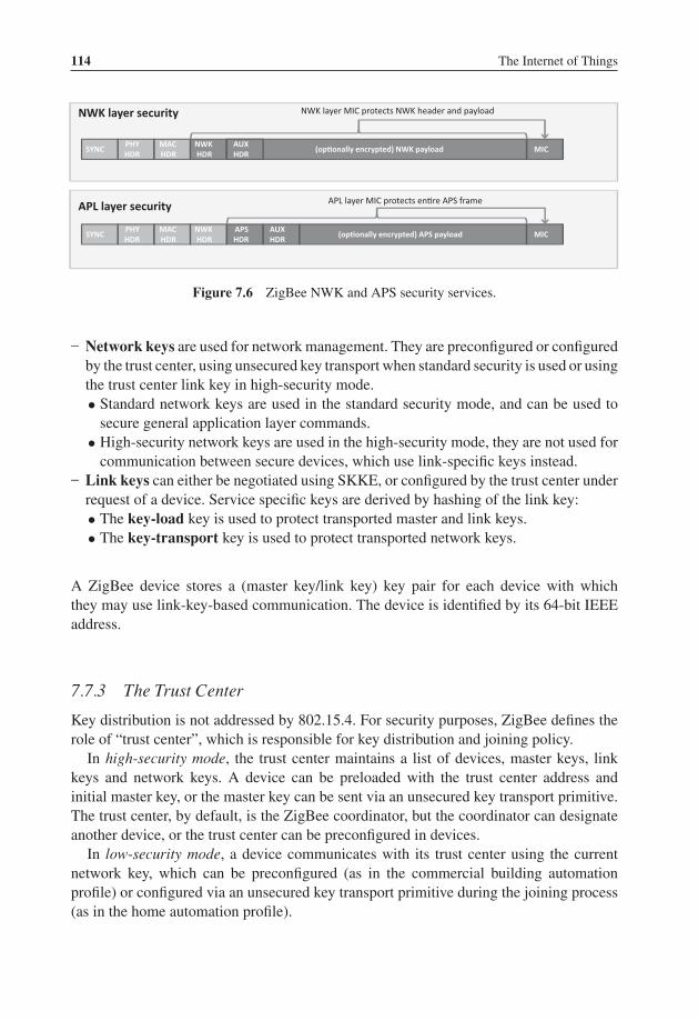
P1: TIX/XYZ P2: ABCJWST118-c07 JWST118-Hersent November 30, 2011 7:53 Printer Name: Yet to Come
114 The Internet of Things
APL layer security
SYNCPHYHDR
MACHDR
NWKHDR
APSHDR
AUXHDR
(op�onally encrypted) APS payload
MIC(op�onally encrypted) NWK payload
NWK layer MIC protects NWK header and payloadNWK layer security
AUXHDR
SYNCPHYHDR
MACHDR
NWKHDR
MIC
APL layer MIC protects en�re APS frame
Figure 7.6 ZigBee NWK and APS security services.
– Network keys are used for network management. They are preconfigured or configuredby the trust center, using unsecured key transport when standard security is used or usingthe trust center link key in high-security mode.• Standard network keys are used in the standard security mode, and can be used to
secure general application layer commands.• High-security network keys are used in the high-security mode, they are not used for
communication between secure devices, which use link-specific keys instead.– Link keys can either be negotiated using SKKE, or configured by the trust center under
request of a device. Service specific keys are derived by hashing of the link key:• The key-load key is used to protect transported master and link keys.• The key-transport key is used to protect transported network keys.
A ZigBee device stores a (master key/link key) key pair for each device with whichthey may use link-key-based communication. The device is identified by its 64-bit IEEEaddress.
7.7.3 The Trust Center
Key distribution is not addressed by 802.15.4. For security purposes, ZigBee defines therole of “trust center”, which is responsible for key distribution and joining policy.
In high-security mode, the trust center maintains a list of devices, master keys, linkkeys and network keys. A device can be preloaded with the trust center address andinitial master key, or the master key can be sent via an unsecured key transport primitive.The trust center, by default, is the ZigBee coordinator, but the coordinator can designateanother device, or the trust center can be preconfigured in devices.
In low-security mode, a device communicates with its trust center using the currentnetwork key, which can be preconfigured (as in the commercial building automationprofile) or configured via an unsecured key transport primitive during the joining process(as in the home automation profile).

P1: TIX/XYZ P2: ABCJWST118-c07 JWST118-Hersent November 30, 2011 7:53 Printer Name: Yet to Come
ZigBee 115
Figure 7.7 Security bootstrapping procedure in high-security mode.
The trust center is notified by ZigBee routers of joining devices by means of an Update-Device command (see Figure 7.7). They can reject or accept the new joiner. In the lattercase the trust center communicates the joiner master key to the router, which relays it tothe joiner. This enables the trust center to establish a link key to the joiner, and to finallysecurely communicate the NWK key to the joiner using a secure Transport-Key command(key-transport key, derived from the link key).
Devices can also request the trust center to compute a link key pair for communicationwith another device: the trust center will communicate the link key to each device usingTransport-Key commands.
7.7.3.1 SKKE
Secure ZigBee devices are configured with a link specific master key for each device theymay need to communicate securely with, or need to authenticate. A link key, distinct fromthe master key, can be negotiated between ZigBee endpoints by using a symmetric keyestablishment (SKKE) scheme using procedures defined in ANSI X9.63-2001.
7.7.3.2 Entity Authentication
ZigBee provides a APSME-AUTHENTICATE.request primitive is used for initiatingentity authentication or responding to an entity authentication initiated by another device.The request includes a random challenge and the response is a hash based on the sharedmaster key for the device pair and frame sequence numbers.

P1: TIX/XYZ P2: ABCJWST118-c07 JWST118-Hersent November 30, 2011 7:53 Printer Name: Yet to Come
116 The Internet of Things
7.7.4 The ZDO Permissions Table
The ZDO optionally comprises a permissions configuration table. This table lists a numberof tasks categories (e.g., ApplicationSettings for authorization to configure bindings,groups, and other application configuration commands) that can be requested from anexternal entity to the ZDO. For each task category, the permissions configuration tablelists the addresses of devices authorized to perform these tasks (or specifies that anydevice is authorized), and specifies whether the related commands need to be securedwith a link-specific key.
7.8 The ZigBee Cluster Library (ZCL)
The cluster library provides support for communication between applications, includingover the air configuration of group tables, reading and setting attribute values, subscribingto certain attribute-value changes, and so on.
7.8.1 Cluster
A cluster is a set of related commands and attributes. Each cluster is defined by a ZigBeeapplication profile and identified by a cluster ID (0x0000 to 0xFFFF). Commands areidentified by a command ID (0x00 to 0xFF), and attributes by an attribute ID (0x0000 to0xFFFF).
Clusters are composed of a server side and a client side. Each application residing ona ZigBee device lists the clusters that it supports as a server in its simple descriptor inputcluster list, and the clusters that it supports as a client in the simple descriptor outputcluster list.
An application that implements the server side typically exposes a set of attributes,and must be able to receive and process the primitives defined by the cluster to read ormanipulate these attributes. It may also support attribute-reporting commands, which aresent to requesting devices that implement the client side of the cluster.
Vice versa an application that implements the client side of the cluster may use any ofthe commands supported by the server side, and must support receiving attribute reportingcommands, if it requests such notifications.
Each cluster is defined only within a given application profile. However, in order to avoidany confusion and to redefine common clusters multiple times, the clusters defined by theZigBee cluster library (ZCL) use the same cluster IDs for each ZigBee public applicationprofile. Table 7.6 lists some of the clusters defined by the ZCL, which therefore have thesame meaning for all public application profiles defined by ZigBee.
Clusters are directional: for each endpoint, the endpoint simple descriptor contains thelist of input clusters (commands that it accepts and properties that can be written to theendpoint), and the list of output clusters (commands that it may send and properties thatmay be read).

P1: TIX/XYZ P2: ABCJWST118-c07 JWST118-Hersent November 30, 2011 7:53 Printer Name: Yet to Come
ZigBee 117
Table 7.6 Some clusters defined by the ZCL
Cluster ID Cluster Name
0x0000 Basic cluster0x0001 Power configuration cluster0x0002 Temperature configuration cluster0x0003 Identify cluster0x0004 Groups cluster0x0005 Scenes cluster0x0006 OnOff cluster0x0007 OnOff configuration cluster0x0008 Level control cluster0x000a Time cluster0x000b Location cluster
Each ZigBee public application profile defines a list of devices, each implementing astandard set of features defined by a list of input and output clusters. Within a given public-application profile, manufacturers can extend that list by using the “manufacturer specificextension” field of the ZCL frame (see Section 7.8.4). An endpoint declares the clusters itsupports in its simple descriptor, which contains the endpoint number, application profileID, application device ID, and application version ID (see Section 7.9), the list of inputand output clusters.
7.8.2 Attributes
Attributes are identified by a 16-bit number. The ZCL library provides commands to:
� read or set attributes;� require reporting on an attribute, either periodic or based on a change of value.
7.8.3 Commands
Commands are identified by an 8-bit number. The first 4 bits of cluster-specific commands(defined only within the scope of a given cluster) are set to zero. For instance, command0x00 of the OnOff cluster (0x0006) means “Off”.
Other identifiers are reserved for cross-cluster commands.
7.8.4 ZCL Frame
The ZigBee cluster library frame (Table 7.7) carries application-specific commands.The general commands (frame type = 00) are listed in Table 7.8.

P1: TIX/XYZ P2: ABCJWST118-c07 JWST118-Hersent November 30, 2011 7:53 Printer Name: Yet to Come
118 The Internet of Things
Table 7.7 ZCL frame format
Field Bytes Field details
Frame Control 1 ------XX : Frame type (00 : cluster for entire app. Profile,01 : cluster specific command, other values reserved)
-----0-- : Manufacturer specific (0 : defined by ZCL, 1manufacturer specific)
----X--- : Direction (0 : client to server)000X---- : Default response (0 enabled, 1 disabled)000----- : Reserved
Manufacturer code 0/2 Present only if the frame is manufacturer specific (Framecontrol bit 6)
Transaction sequencenumber
1 Matching of request command frames and responsecommand frames
Command identifier 1 e.g., 0x42: toggle
Table 7.8 ZCL general commands
Commandidentifier Command Usage
0x00 Read attributes Read a list of attributes, whose 16-bit identifiers arepassed as payload
0x01 Read attributes response Includes a list of attribute records as payload. Eachattribute record is as follows: Attribute identifier(16 bit) | Status(Success or error: 8 bit) | Attributedata type (0/8 bit) | Attribute value (variable).Array types are encoded as element type | numberof elements | list of elements.
0x02 Write attributes Write a list of attributes, as described by a list ofattribute records in payload.
0x03 Write attributes undivided Write attributes, all or nothing mode.0x04 Write attributes response Response with a list of status codes, for each
parameter.0x05 Write attributes no response Write attributes, best effort mode.0x06 Configure reporting Only specific attributes support reporting in a cluster.
The list of attribute reporting configurationrecords passed as parameter includes minimal andmaximal reporting intervals, the minimum changeof the attribute that should trigger reporting. Thiscommand may be sent by a client to a server toconfigure reporting, or by a server to a client todescribe its future reporting parameters.
(Continued)

P1: TIX/XYZ P2: ABCJWST118-c07 JWST118-Hersent November 30, 2011 7:53 Printer Name: Yet to Come
ZigBee 119
Table 7.8 (Continued)
Commandidentifier Command Usage
0x07 Configure reporting response0x08 Read reporting configuration Request to get the reporting configuration
parameters for one or more attributes0x09 Read reporting configuration
response0x0a Report attributes Reporting for one or more attributes of a cluster,
according to a previously configured reportingrelationship (binding)
0x0b Default response Basic success/error response0x0c Discover attributes Specifies a starting 16-bit attribute identifier and
maximum number of identifiers to report0x0d Discover attributes response0x0e Read attributes structured Used to read only specific index positions (up to 15)
for array-type attributes0x0f Write attributes structured Used to write only specific index positions (up to
15) for array-type attributes0x10 Write attributes structured
response
7.9 ZigBee Application Profiles
An application profile defines a set of messages and attributes standardized for use in aparticular context. Application profiles are identified by an application profile ID (0x0000to 0xFFFF). Each manufacturer can define proprietary messages within its own privateapplication profile, but the ZigBee alliance defines a set of public application profiles,which enable cross-vendor interoperability for the target applications. Profile IDs 0xBF00to 0xFFFF are reserved for manufacturer specific profiles (MSP), and must be requestedfrom the ZigBee alliance. Profile IDs 0x0000 to 0x7FFF are reserved for public applicationprofiles, and are listed in Table 7.9.
Each ZigBee public profile contains a list of devices identified by a device ID. Eachdevice implements a standard set of features defined by a list of input and output clusters,and a list of attributes (some optional, some mandatory). Within a given public applicationprofile, manufacturers can extend that list by using the “manufacturer-specific extension”field of the ZCL (see Section 7.8.4).
7.9.1 The Home Automation (HA) Application Profile
The HA profile is by far the most widely implemented by manufacturers. While ZigBeedoes not specify use of nonvolatile memory, the HA profile does: nodes should retain

P1: TIX/XYZ P2: ABCJWST118-c07 JWST118-Hersent November 30, 2011 7:53 Printer Name: Yet to Come
120 The Internet of Things
Table 7.9 ZigBee public application profiles
Public Application Profile Profile ID Usage
Home Automation HA 0x0104 Security, HVAC, LIGHTINGCONTROL, ACCESSCONTROL, IRRIGATION. . .
Commercial BuildingAutomation
CBA 0x0105 Security, HVAC, AMR, lightingcontrol, access control
Industrial Plant Monitoring IPM 0x0101 Asset management, process control,environmental control, energymanagement
TelecommunicationsApplications
TA 0x0107 Information delivery in hot zones,public information enquiry,location-based services, remotecontrol (TV, DVD), cell phone
Automatic (Advanced)Metering Initiative orSmart Energy 1
AMIZSE 1
0x0109
Personal Home and Hospital(Health) Care
PHHC 0x0108 Patient monitoring, Fitnessmonitoring.
their configuration (PAN ID, address, group IDs, etc. . . .) even after a power down. Thisfacilitates battery replacement and network restarts after power outages (silent rejoin, seeSection 7.3.3).
The HA profile determines the following settings:
– It uses stack profile 0x01 or 0x02.– Channels 11, 14, 15, 19, 20, 24, 25 are preferred.– The trust center link key is hardcoded in the profile, the trust center distributes a network
key.– The minimum number of entries of entries in the broadcast transaction table (BTT, see
Section 7.4.5.1) is nine.
The standard devices defined by the home automation public application profile arecharacterized by the mandatory clusters that they must support. Mandatory and optional“common clusters” are defined for all HA devices:
– Server side: mandatory support of basic and identify clusters. Optional support for powerconfiguration, device temperature configuration, alarms, meter, and manufacturer-specific clusters.
– Client side: optional support for meter, and manufacturer-specific clusters.
The HA profile also lists mandatory and optional clusters specific to each device type.Table 7.10 lists some examples.
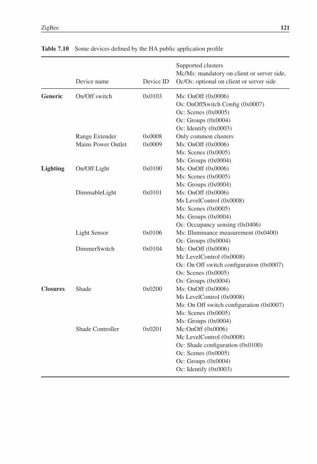
P1: TIX/XYZ P2: ABCJWST118-c07 JWST118-Hersent November 30, 2011 7:53 Printer Name: Yet to Come
ZigBee 121
Table 7.10 Some devices defined by the HA public application profile
Device name Device ID
Supported clustersMc/Ms: mandatory on client or server side,Oc/Os: optional on client or server side
Generic On/Off switch 0x0103 Ms: OnOff (0x0006)Os: OnOffSwitch Config (0x0007)Oc: Scenes (0x0005)Oc: Groups (0x0004)Oc: Identify (0x0003)
Range Extender 0x0008 Only common clustersMains Power Outlet 0x0009 Ms: OnOff (0x0006)
Ms: Scenes (0x0005)Ms: Groups (0x0004)
Lighting On/Off Light 0x0100 Ms: OnOff (0x0006)Ms: Scenes (0x0005)Ms: Groups (0x0004)
DimmableLight 0x0101 Ms: OnOff (0x0006)Ms LevelControl (0x0008)Ms: Scenes (0x0005)Ms: Groups (0x0004)Oc: Occupancy sensing (0x0406)
Light Sensor 0x0106 Ms: Illuminance measurement (0x0400)Oc: Groups (0x0004)
DimmerSwitch 0x0104 Mc: OnOff (0x0006)Mc LevelControl (0x0008)Oc: On Off switch configuration (0x0007)Os: Scenes (0x0005)Os: Groups (0x0004)
Closures Shade 0x0200 Ms: OnOff (0x0006)Ms LevelControl (0x0008)Ms: On Off switch configuration (0x0007)Ms: Scenes (0x0005)Ms: Groups (0x0004)
Shade Controller 0x0201 Mc:OnOff (0x0006)Mc LevelControl (0x0008)Oc: Shade configuration (0x0100)Oc: Scenes (0x0005)Oc: Groups (0x0004)Oc: Identify (0x0003)

P1: TIX/XYZ P2: ABCJWST118-c07 JWST118-Hersent November 30, 2011 7:53 Printer Name: Yet to Come
122 The Internet of Things
Table 7.10 (Continued)
Device name Device ID
Supported clustersMc/Ms: mandatory on client or server side,Oc/Os: optional on client or server side
HVAC Heating / Cooling unit 0x0300 Ms:OnOff (0x0006)Mc: Thermostat (0x0201)Os: Fan control (0x0202)Os: Level control (0x0008)Os: Groups (0x0004)
Thermostat 0x0301 Ms: Thermostat (0x0201)Os: Scenes (0x0005)Os: groups (0x0004)Os: Thermostat user interface configuration
(0x0204)Os/ Oc: Fan control (0x0202)Os / Oc: Temperature measurement
(0x0402)Os / Oc:: Occupancy sensing (0x0406)Os/Oc: Relative humidity measurement
(0x0405)Temperature sensor 0x0302 Ms: Temperature measurement (0x0402)
7.9.2 ZigBee Smart Energy 1.0 (ZSE or AMI)
ZigBee Smart Energy 1.0 is a public application profile (profile 0x0109), documented in“ZigBee SMART ENERGY PROFILE SPECIFICATION (rev 15, 1/12/2008)”. It definesthe smart energy devices and clusters required to build an energy-management system(EMS).
The ZigBee Smart Energy 1 (ZSE) public application was defined to enable usage ofZigBee for automatic metering, demand response and prepayment applications requiredby utilities. The ZSE was defined just before ZigBee decided that its next version wouldrely on IP, and ZSE was the first application profile to be entirely redesigned in the contextof IP, the new specification is called ZigBee Smart Energy 2.0 (see Section 13.4).
ZSE dedicates a secure HAN (use of security is mandatory) to the utility, and definesthe communication primitives used between the energy service portal controlled by theutility, and devices located in the end user primitives, such as home displays or loadcontrol devices. As the displays and other ZigBee devices may be deployed by end userson their home network using HA, ZSE also defines an extension (the “stub APS”) tothe ZigBee core specification enabling limited single hop communications between twoPANs (the utility PAN and the user home area network).
ZSE defines several new clusters listed in Table 7.11.
P1: TIX/XYZ P2: ABCJWST118-c07 JWST118-Hersent November 30, 2011 7:53 Printer Name: Yet to Come
ZigBee 123
7.9.2.1 Security
SE makes a mandatory use of link keys (preconfigured or commissioned), which areotherwise optional in ZigBee. However, a master key is not used or preconfigured inZigBee SE devices, which do not operate in “high-security” mode.
ZigBee smart energy devices use a network key allocated by the trust center, using thekey establishment cluster with a preconfigured trust center link key. The link key is alsoreplaced by the trust center as part of this security bootstrapping process. ZigBee smartenergy networks will not generally send keys in the clear.
ZigBee SE envisions that two separate home area networks will be used:
– One network for the exclusive use of the utility company, interconnecting the energyservices portal, in-home display(s) and load control devices.
– One separate network for the home owner use, including home automation devices,in-home displays (ihd), a home energy management console, and smart appliances.
The links between the automatic metering infrastructure (AMI) servers and the homearea networks may use a combination of non-ZigBee and ZigBee networks. The energyservices portal may control a collection of sub-ESPs, in a cascading fashion, so thatZigBee can optionally also be used as a neighborhood area network (NAN).
Since all ZigBee SE devices are configured with multiple keys (link keys and thenetwork key), ZigBee SE defines which cluster uses which key. All the ZigBee SEclusters use application link keys, but most general clusters (e.g., basic cluster, alarmcluster, identify cluster) use the network key.
7.9.2.2 Smart Energy Extensions of ZigBee
ZigBee SE defines a simplified APS layer designed for basic “inter-PAN” communication,that is, communication between a PAN and a device that has not joined. The specificationmentions the “refrigerator magnet” with an LCD screen as a target.
Such messages can be sent unicast, broadcast or sent to a group, but without anysecurity.
7.9.2.3 Smart Energy Devices
ZigBee SE defines the following “smart energy” devices:
Energy Service Portal (ESP, Device Id 0x0500)The energy service portal is a server controlled by the utility company that connectsto the metering and energy management devices within the home. The ESP acts as thecoordinator and trust center of the network.

P1: TIX/XYZ P2: ABCJWST118-c07 JWST118-Hersent November 30, 2011 7:53 Printer Name: Yet to Come
124 The Internet of Things
The ESP must support the server side of the price, message, demand response/loadcontrol and time clusters, and optionally of the complex metering, simple metering andprepayment. It may support the client side of the simple metering, complex metering,price and prepayment clusters.
Metering Device (Device Id 0x0501)A metering device must support the client side of the metering cluster, optionally of thecomplex metering cluster. It may support the client side of the metering prepayment, priceand message clusters.
In-Premises Display Service (Device Id 0x0502)The device is designed to be used as a simple user interface, displaying graphs or messages,and able to signal button press events. It must implement the client side of at least one ofthe price, simple metering and messaging clusters.
Programmable Communicating Thermostat (PCT, Device Id 0x0503)This device is designed to control heating and cooling systems. It must implement theclient side of the Demand response/load control and time clusters. It may implement theclient side of the prepayment, price, simple metering and message clusters.
Load Control Device (Device Id 0x0504)This device is designed to manage the electric consumption of devices in a generic way.It must implement the client side of the demand response/load control and time clusters.It may implement the client side of the price message cluster.
Range Extender Device (Device Id 0x0008)A device announcing this device Id must be a pure ZigBee router, not supporting anyother function.
Smart Appliance Device (Device Id 0x0505)Smart appliances are able to participate in energy-management policies. They must im-plement the client side of the price and time clusters, and optionally of the demandresponse/load control and message clusters.
Prepayment Terminal Device (Device Id 0x0506)This device is not fully specified yet. It is designed to support advance payment of services,and various display functions.
7.9.2.4 Smart Energy Clusters
Demand Response and Load Control Cluster (0x0701)Server-Side Commands

P1: TIX/XYZ P2: ABCJWST118-c07 JWST118-Hersent November 30, 2011 7:53 Printer Name: Yet to Come
ZigBee 125
Table 7.11 New clusters defined by ZigBee smart energy
Price 0x0700Demand response and load control 0x0701Simple metering 0x0702Message 0x0703Registration 0x0704AMI tunneling (complex metering) 0x0705Prepayment 0x0706
Load control event (0x00). This event is sent to the devices asked to implement a loadcontrol action, and specifies the actions required. It includes the following parameters:
� Issuer Event ID: unique identifier that will be used to identify future event reports relatedto this demand response and load control event.
� Device Class: bit-encoded field indicating the device classes (end devices actually per-forming the energy-demand response, as opposed to their ZigBee controllers) needingto participate in an event. The classes defined include HVAC compressors, Strip heaters,water heaters, electric vehicles, and so on.
� Utility Enrolment Group: both the utility enrolment group field and the device classmust match the target device configured values, otherwise it will ignore the command.
� Start Time: UTC Timestamp or 0x00000000 for “now.”� Criticality Level: levels 1 to 9 are currently defined. Participation in levels 1 to 6 is
voluntary, participation in level 9 is mandatory. Level 1 signals an abnormal percentageof nongreen sources in the delivered energy.
� Cooling and heating temperature offsets: offsets, in units of 0.1 ◦C, to the local tem-perature setpoint of the thermostat (added for cooling systems, subtracted for heatingsystems), noncumulative across sequential demand response events. 0xFF when notused.
� Cooling and heating temperature setpoint: request to replace the current setpoint by theindicated value between –273 ◦C and 327 ◦C in units of 0.01 ◦C, set to 0x8000 whennot used.
� Average Load Adjustment Percentage: defines a load offset of −100 to +100 pointsrelative to 100%, with a resolution of 1 point. Interpretation is specific to the clientimplementation. Set to 0x80 when not used.
� Duty cycle: a percentage of time between 0 and 100%, 0xFF when not used.� Event Control: flags to indicate whether randomization of the start and end times is
required.
Cancel load control event (0x01): cancellation order specifying the issuer event Id,utility enrollment group and device classes concerned. Flag to optionally override the end

P1: TIX/XYZ P2: ABCJWST118-c07 JWST118-Hersent November 30, 2011 7:53 Printer Name: Yet to Come
126 The Internet of Things
randomization settings of the original load control event, and desired cancellation UTCtime (0x00000000 for “now”).
Cancel all load control events (0x02): same as the cancel load control event command,without the filtering parameters.
Client SideThe client side of the load control/demand response cluster must be able to store at least
3 scheduled events. Events exceeding the storage capacity should be retrieved as soon aspossible using command “get scheduled events”.
The client side maintains several attributes:
– The utility enrolment group;– The start randomization period, and the stop randomization period, in minutes;– The device class bitmask.
It implements two commands:
– Get Scheduled Events (0x01), which asks the server side to resend up to a certainnumber of load control commands scheduled to start at or after the specified UTC timestamp.
– Report Event Status (0x00), which reports the time at which the load-control event(identified by its event ID) was effectively executed, the criticality level, the cooling orheating set points, load adjustment percentage, duty cycle that were applied. The eventstatus parameter contains the current state of the load control event: started, completed,user opted in or opted out before or during the event, canceled, superseded, and errorconditions. An electronic signature ensures nonrepudiation.
Simple Metering Cluster (0x0702)Server-Side Attributes
Attribute setidentifier
Attributes
0x00Readinginformationset
CurrentSummationDelivered (0x00),CurrentSummationReceived (0x01),
Most recent summedvalue of energy/gas/waterdelivered to, or providedby the premises.
CurrentMaxDemandDelivered (0x02),CurrentMaxDemandReceived (0x03),CurrentMaxDemandDeliveredTime (0x08),CurrentMaxDemandReceivedTime (0x09)
Instant value of maximumrates, and when they weremeasured.
DFTSummation (0x04),DailyFreezeTime (0x05),
Snapshot of CurrentSum-mationDelivered taken atinstantDailyFreezeTime

P1: TIX/XYZ P2: ABCJWST118-c07 JWST118-Hersent November 30, 2011 7:53 Printer Name: Yet to Come
ZigBee 127
PowerFactor (0x06),ReadingSnapShotTime (0x07),
Average power factor
0x01TOUinformationSet
CurrentTierNSummationReceivedCurrentTierNSummationDelivered
Where N = 1 to 6, partialsummation counters perprice tier (defined perperiod in the time of useschedule or per price tier).
0x02 Meterstatus
Status (0x00) Status flags: tamperdetected, leaks, etc.
0x03Formatting
UnitOfMeasure (0x00), Multiplier (0x01),Divisor (0x02), SummationFormatting(0x03), DemandFormatting (0x04),HistoricalConsumptionFormatting (0x05),
Set of attributes used totransform counters todisplayable values: units,scaling factors.
0x04 ESPhistoricalconsumption
InstantaneousDemand (0x00),CurrentDayConsumptionDelivered(0x01),CurrentDayConsumptionReceived(0x02), PreviousDayConsumptionDelivered(0x03), PreviousDayConsumptionReceived(0x04),CurrentPartialProfileIntervalStartTimeDe-livered (0x05), CurrentPartialProfileIntervalStartTimeReceived (0x06),CurrentPartialProfileIntervalValueDeliv-ered (0x07),CurrentPartialProfileIntervalValueReceived(0x08)
Accumulators sincemidnight for the currentday, since the start time ofthe current profileinterval, for the previousday
0x05 Loadprofileconfiguration
MaxNumberOfPeriodsDelivered (0x00) maximum number ofintervals the device iscapable of returning inone get profile responsecommand.
0x06 SupplyLimit
CurrentDemandDelivered (0x00),DemandLimit (0x01),DemandIntegrationPeriod (0x02),NumberOfDemandSubintervals (0x03)
Demand is integratedduring the demandintegration period, and theintegration result iswritten tocurrentDemandDeliveredat the end of eachsubinterval.
P1: TIX/XYZ P2: ABCJWST118-c07 JWST118-Hersent November 30, 2011 7:53 Printer Name: Yet to Come
128 The Internet of Things
Server-Side CommandsGetProfileResponse (0x00) returns a number of period accumulators for periods endingbefore a specified EndTime.
RequestMirror (0x01): request the ESP to mirror metering device data, usingRequestMirrorResponse command.
commandRemoveMirror (0x02): request the ESP to remove its mirror of metering devicedata.
Client-Side CommandsGetProfile (0x00): requests a number of period accumulators for periods ending before aspecified EndTime, for received or for delivered quantities.
RequestMirrorResponse (0x01): the ESP informs a sleepy metering device it has theability to store and mirror its data, which should be sent to the indicated endpointID.
RemoveMirror (0x02): the ESP no longer has the ability to mirror data.
Price Cluster (0x0700)Server-Side Attributes6 price tiers labels are defined, by attributes “TierXpriceLabel” (0x0000 to 0x0006). Theprice tiers are defined by command publish price.
Client-Side Commands
– getCurrentPrice (0x00): initiates a publish price command for the current time.– getScheduledPrices (0x01): initiates a publish price command for all currently sched-
uled times after the provided time stamp (up to a maximum number of scheduled timesalso specified in the command).
Server-Side CommandsPublish price (0x00): this command defines a new price tier and is sent in response to agetCurrentPrice or getScheduledPrices command. It contains the following subfields:
� ProviderID: unique Id of the commodity provider;� Rate Label: 12 character UTF8 string related to current rate;� Issuer Event ID: unique identifier for this pricing information, must increase when
newer prices are published for the same period;� Current Time: UTC time of the sending node;� Unit of measure: 8-bit field defining the commodity and unit of measure;� Currency� Price Trailing Digit and Price tier: bit field indicating the price tier for this rate, and
the position of the decimal point in the published price;

P1: TIX/XYZ P2: ABCJWST118-c07 JWST118-Hersent November 30, 2011 7:53 Printer Name: Yet to Come
ZigBee 129
� Number of price tiers and Register tier: number of price tiers in use (0 to 6), for thecurrent tier, indication of which CurrenttierXSummationDelivered accumulator relatesto the current price tier;
� StartTime: UTC start time of the current rate signal, 0x00000000 means “now”;� Duration in minutes: validity of this price signal. 0xffffffff means “until changed”;� Price: price per base unit;� PriceRatio (optional): ratio to the “normal” tariff;� Generation Price (optional): price for commodity received from the premises;� AlternateCostDelivered, Alternate cost unit and alternate cost trailing digit: cost using
an alternate measure, for example, grams of CO2 per kWh.
Messaging Cluster (0x0703)Server-Side CommandsDisplayMessage (0x00): specifies the level of importance of the message, whether aconfirmation is required, and the number of minutes the message must be displayed.
CancelMessage (0x01)
Client-Side CommandsGetLastMessage (0x00): request to send a DisplayMessage command
MessageConfirmation (0x01): used to acknowledge a message, provides a timestamp.
Smart Energy Tunneling (Complex Metering) Cluster (0x0704)Not defined yet, this cluster is a placeholder for future tunneling mechanisms for moresophisticated metering protocols, for example, C.12 or DLMS/COSEM.
Prepayment Cluster (0x0705)Not defined yet.
7.10 The ZigBee Gateway Specification for Network Devices
The ZigBee Gateway specification for network devices, Version 1.0, was released onJuly 27th 2011. It had been a work in progress since 2007. This specification definesseveral possible communication protocols between ZigBee gateway devices (ZGD) thatimplement a bidirectional interface between ZigBee 1.0 PANs and IP networks, and IPhost applications (IPHA).
The ZGD provides access to:
� ZCL operations: read and write attributes, configure notifications and report events;� ZDO operations;� Macro operations simplifying network and service discovery;� Endpoint management;
P1: TIX/XYZ P2: ABCJWST118-c07 JWST118-Hersent November 30, 2011 7:53 Printer Name: Yet to Come
130 The Internet of Things
� Its own ZigBee information bases (AIB, NIB, and PIB attributes);� Network startup and join functions on behalf of the IPHA;� Security material configuration and operations.
The communication between ZGDs and IPHAs is bidirectional, both act as client andserver. The IPHA calls procedures implemented by the ZGD, and the ZGD calls eventhandlers of the IPHA. These RPC functions have been specified in an abstract, protocol-independent request-response format that needs to be complemented by a protocol bindingspecification.
Some ZGD procedures operate only in blocking mode, while other procedures offera choice of blocking or nonblocking mode (such nonblocking procedures provide aCallbackDestination, which is an IPHA callback URL or an empty string if the IPHAuses polling). All IPHA event handlers are nonblocking.
ZigBee PAN messages received by the ZGD are processed by one or more ZGD callbackhandlers, which decode and feed them to requesting IPHAs. The configuration of thesecallback handlers is persistent across ZGD power cycles.
Version 1.0 of the ZigBee gateway specification proposes three possible network bind-ings implementing the ZGD to IPHA remote procedure calls: a SOAP binding, a RESTbinding, and a GRIP (gateway remote interface protocol) binding.
7.10.1 The ZGD
The ZGD itself is a ZigBee device. As such it should support the ZigBee commissioningcluster, as well as mandatory ZDO client and server clusters.
The ZGD functions belong to several categories: gateway management object, Zig-Bee device profile, ZigBee cluster library, application support sublayer, inter-PAN, andnetwork layer.
An IPHA can access:
� APS commands to read and modify the ZGD configuration by using a set of APSfunctions. It can read or set descriptors (ConfigureNodeDescriptor, GetNodeDescriptor,GetNodePowerDescriptor, ConfigureUserDescriptor, GetUserDescriptor), managelocal ZGD endpoints (ConfigureEndpoint, ClearEndpoint), send and receive APSframes (SendAPSMessage / NotifyAPSMessageEvent), manipulate local groups (Ad-dGroup, RemoveGroup, RemoveAllGroups, GetGroupList), and read local bindings(GetBindingList).
� Network layer commands to get access to the Network layer management en-tity (NLME) of the ZGD (FormNetworkProcedure, FormNetworkEvent, StartRouter,StartRouterEvent, Join, JoinEvent, Leave, LeaveEvent, Reset, ResetEvent, Discover-Networks, DiscoverNetworksEvent, PerformEnergyScan, PerformEnergyScanEvent,

P1: TIX/XYZ P2: ABCJWST118-c07 JWST118-Hersent November 30, 2011 7:53 Printer Name: Yet to Come
ZigBee 131
NetworkStatusEvent, PerformRouteDiscovery, PerformRouteDiscoveryEvent, Send-NWKMessage, NotifyNWKMessageEvent).
An IPHA can send arbitrary ZDP frames by using the SendZDPCommand ZGD functionand receive arbitrary ZDP frames by implementing a NotifyZDPEvent event handler.
The ZGD also provides access to the ZCL. An IPHA can send and receive arbitraryZCL commands by using the SendZCLCommand ZGD function and implementing theNotifyZCLEvent event handler.
In addition the ZGD supports the specific gateway management object (GMO). TheGMO provides functions:
– Enabling the IPHA to retrieve the ZGD version and feature set (GetVersion).– Enabling read/write of ZGD information base (Get/Set).– Event CallBack management (CreateCallBack, DeleteCallBack, ListCallBacks) and
polling by IPHA (PollCallBack, PollResults, UpdateTimeOut).– Facilitating network and service discovery (StartNodeDiscovery, NodeDiscoveryEvent,
NodeLeaveEvent, ReadNodeCache, StartServiceDiscovery, ServiceDiscoveryEvent,GetServiceDescriptor, ServiceDiscoveryEvent, ReadServiceCache).
– Controlling the Gateway insertion into the PAN (StartGatewayDevice, StartGateway-DeviceEvent, ConfigureStartupAttributeSet, ReadStartupAttributeSet).
– Managing address aliases (CreateAliasAddress, DeleteAliasAddress, ListAddresses):In order to facilitate the mapping of addresses between the PAN network (short 16-bit addresses may change in the PAN) and the IPHA, the ZGD maintains an addressalias table where IPHAs can associate their own alias to any 64-bit address. The IPHAor ZGD may use special code 0x10 in the Destination/source address mode2 of ZDPmessages to indicate use of an alias address: the ZGD will translate to 64-bit or 16-bitaddresses as required.
7.10.2 GRIP Binding
The gateway remote interface protocol (GRIP) is a lightweight request/response protocolbuilt over SCoP.
The secured connection protocol (SCoP) was designed in the context of the ZigBee bridge devicespecification as an IP tunneling protocol between ZigBee PAN gateways. It provides support fordatagram and stream-oriented communications as well as fragmentation by means of a socket-like
2 APSDE-DATA.request DstAddrMode parameter values : 0x00 = DstAddress and DstEndpoint notPresent; 0x01 = 16-bit group address for DstAddress; DstEndpoint not present; 0x02 = 16-bit address forDstAddress and DstEndpoint present; 0x03 = 64-bit extended address for DstAddress and DstEndpoint present;0x04 – 0xff = reserved.

P1: TIX/XYZ P2: ABCJWST118-c07 JWST118-Hersent November 30, 2011 7:53 Printer Name: Yet to Come
132 The Internet of Things
interface provided by the SCoP data entity (SCDE), on top of UDP, TCP or TLS. SCoP securityleverages CCM∗ (SCoP security service SCSS). Management services are provided by the SCoPmanagement entity (SCME).
SCoP messages target a specific service (identified by a service identifier code), on the targetgateway. Currently the supported services are SCoP service (hello, goodbye, keepalive commands),bridge service and GRIP service.
The GRIP API provides a GRIDE-DATA request that must be provided withtarget information (DestIPVersion, DestIPAddress, DestPort), desired transport pa-rameters (TransportMode, SecurityLevel) and application-level parameters (targetFunctionDomain, FunctionCategory, ManufacturerCode, FunctionIdentifier, Function-Parameters).
Requests are provided to the target GRIP application by means of the GRIDE-DATA.indication API. Responses are returned to the querying GRIP application by meansof the GRIDE-DATA.response API, and specifies a Status code as well as a function result(an octet string).
The GRIP binding specifies specific GRIP function codes and parameter formats totransport all the generic ZGD procedures defined in Section 7.10.1. The following functioncategories are defined: Manufacturer specific, GMO, ZDP, ZCL, APS, INTERPAN, NWK.Parameter encoding uses ASN.1 distinguished encoding rules (DER).3
7.10.3 SOAP Binding
The SOAP binding specifies a standard web services interface by means of a WSDLdocument. All the generic ZGD procedures defined in Section 7.10.1 are covered.
7.10.4 REST Binding
Due to the resource oriented design pattern of REST, the REST binding for the ZDGfunctional protocol is not as straightforward as the GRIP or SOAP bindings.
A set of resources are defined to represent the ZGD (Figure 7.8), each ZigBee networkand each ZigBee node (Figures 7.9 and 7.10), each resource is addressable with an
3 ISO 8825, 1998: Information Technology. ASN.1 Encoding rules: Specification of Basic Encoding Rules(BER), Canonical Encoding Rules (CER) and Distinguished Encoding Rules (DER). International StandardITU-T X690 (1997) | ISO/IEC 8825-1:1998.

P1: TIX/XYZ P2: ABCJWST118-c07 JWST118-Hersent November 30, 2011 7:53 Printer Name: Yet to Come
ZigBee 133
version /RestIfc/zgd/version
/RestIfc/zgd
1
energy
ib /RestIfc/zgd/ib
<A�ribute> /RestIfc/zgd/ib/<A�ribute>
requests /RestIfc/zgd/requests
<Req id> /RestIfc/zgd/requests/<Req id>
net
<Extended PANID> /RestIfc/zgd/0012213344556677
reset
startup
networks
<address> /RestIfc/zgd/networks/<address>
Networks a�ached to the ZGD : network forma�on, Start router, Join procedure, reset, discover networks
Perform energy scan
ZGD version informa�on : VersionIden�fier,FeatureSetIden�fier, RPCProtocol, ManufacturerVersion
1
ZGD Gateway informa�on base
0..*
A�ribute 0x00 : ZigBee radio statuse.g. 0x07 : has formed a network
Pending REST requests
REST requests results
0..*
A specific network a�ached to the ZGD/RestIfc/zgd/networks
/RestIfc/zgd/energy
/RestIfc/zgd/reset Startup parameters
/RestIfc/zgd/startup
Network resources/RestIfc/zgd/net
Figure 7.8 ZGD REST resources overview.
net
default
callbacks
wsnnodes
<address>
Services
<Extended PANID> /net/0012213344556677
ib /net/default/ib
<A�ribute> /net/default/ib/0x00
/net/default/callbacks
<name> /net/default/callbacks/<name>
aliases /net/default/aliases
<alias> /net/default/aliases/<alias>
discovery /net/default/discovery
localnode
allwsnnodes
/net/default/wsnnodes
/net/default/wsnnodes/a0f09be70f459e003
Network, Applica�on and Physical informa�on base
A�ribute 0x07 : ZigBee radio status
/net/default
Default network if the ZGD has only onetransceiver
Extended PANID of a specific PAN formed orjoined by the ZGD
1
0..*
Ac�ve CallBacks for the network
1
0..*
Address aliases
Route discovery func�on
ZigBee nodes in the network
0..*
0..*
0..*
0..*
1
1
The ZGD as local node
Resource for broadcas�ng to all nodes
Ac�ve services (endpoints)
Figure 7.9 Overview of network and node resources.

P1: TIX/XYZ P2: ABCJWST118-c07 JWST118-Hersent November 30, 2011 7:53 Printer Name: Yet to Come
134 The Internet of Things
wsnnodes
localnode
Services
[ep]
nodedescriptor
powerdescriptor
userdescriptor
epgroups
[ep]
[group]
bindings
permitjoin
/wsnnodes/localnode1
The ZGD as local node
Ac�ve services, a GET starts ServiceDiscoveryand reads the service cache
/wsnnodes/localnode/services1
0..*
1
/wsnnodes/localnode/services/21
Ac�ve endpoint, a GET retrieves theServiceDescriptors
/wsnnodes/localnode/nodedescriptor
/wsnnodes/localnode/powerdescriptor
/wsnnodes/localnode/userdescriptor
/wsnnodes/localnode/epgroups
1
1
1
1 Use POST to add groups
0..* Group addresses associated to an endpoint, use DELETE to remove all groups
0..* Group address to endpoint associa�on
1
1
/wsnnodes/localnode/bindings
/wsnnodes/localnode/permitjoin
Device bindings
Permitjoin procedure
wsnconnec�on
message
1 Ac�ve callbacks on a given network
Use POST to send APS message or ZCL command
Figure 7.10 Overview of ZigBee node resources.
URL. Each ZGD function is implemented as a state transfer between the IPHA and theappropriate resource: For instance, the GetVersion function, used by the IPHA to discoverthe features of a ZGD, is implemented as a read operation on the “version” resource ofthe ZGD.
Asynchronous notifications (responses and events) use a special resource hosted by theIPHA. The IPHA declares the URI of this resource to the ZGD using the CreateCallBackREST operation, and can also specify a specific callback URI in each REST requestsupporting the CallBackDestination parameter.
The resources are represented by XML documents, specified as part of the RESTbinding.
7.10.5 Example IPHA–ZGD Interaction Using the REST Binding
The IPHA may read any resource exposed by the ZGD, for instance
HTTP GET:http://’’ZGD_IP_Addr:ZGD_PORT’’/RestIfc/zgd/version
And the ZGD responds with the requested resource representation
P1: TIX/XYZ P2: ABCJWST118-c07 JWST118-Hersent November 30, 2011 7:53 Printer Name: Yet to Come
ZigBee 135
<tns:Info xmlns:tns=’’http://www. zigbee.org/GWGSchema’’ >
<tns:Status>
<tns:code>0x00</tns:code>
</tns:Status>
<tns:Detail>
<tns:Version>
<tns:VersionIdentifier>0x01</tns:VersionIdentifier>
<tns:FeatureSetIdentifier>0x00</tns:FeatureSetIdentifier>
<tns:RPCProtocol>0x0004</tns:RPCProtocol>
<tns:ManufacturerVersion>1.1</tns:ManufacturerVersion>
</tns:Version>
<tns:Detail>
</tns:Info>
In this example we suppose that the IPHA needs to allocate a dedicated endpoint onthe ZGD. It therefore begins by registering a new endpoint on the ZGD. In the followingexample we use a synchronous transaction. The IPHA could have use an asynchronousmethod by specifying a callback URI in parameter CallbackDestination of request URIsent to the ZGD.HTTP POST: HTTP POST: http://’’ZGD_IP_Addr:ZGD_PORT’’/
localnode/services
<?xml version=’’1.0’’ encoding=’’UTF-8’’?>
<tns:SimpleDescriptorxmlns:tns=’’http://www. zigbee.org/GWGSchema’’ >
<tns:ApplicationProfileIdentifier>0x0104</tns:ApplicationProfileIdentifier>
<tns:ApplicationDeviceIdentifier>0x0002</tns:ApplicationDeviceIdentifier>
<tns:ApplicationDeviceVersion>0x00</tns:ApplicationDeviceVersion>
<tns:ApplicationInputCluster>0x0000</tns:ApplicationInputCluster>
<tns:ApplicationInputCluster>0x0003</tns:ApplicationInputCluster>
<tns:ApplicationInputCluster>0x0004</tns:ApplicationInputCluster>
<tns:ApplicationInputCluster>0x0005</tns:ApplicationInputCluster>
<tns:ApplicationInputCluster>0x0006</tns:ApplicationInputCluster>
<tns:ApplicationOutputCluster>0x0003</tns:ApplicationOutputCluster>
</tns:SimpleDescriptor>

P1: TIX/XYZ P2: ABCJWST118-c07 JWST118-Hersent November 30, 2011 7:53 Printer Name: Yet to Come
136 The Internet of Things
The IPHA did not request a specific endpoint, therefore it will be allocated by the ZGD.If the request succeeds, the IPHA will receive a response similar to the following:
<tns:Info xmlns:tns=’’http://www. zigbee.org/GWGSchema’’ >
<tns:Status>
<tns:code>0x00</tns:code>
</tns:Status>
<tns:Detail>
<tns:endpoint>0x23</tns:endpoint>
<tns:Detail>
</tns:Info>
This is an example of a synchronous response. When using an asynchronous mode, theresponse would include a request identifier attribute allocated by the ZGD.
The IPHA has the option of registering a callback function bound to this endpoint orto all endpoints, by invoking an HTTP POST request to [NwkRootURI]/callbacks thatspecifies filters which will be used by the ZGD to identify messages that will be notifiedto the IPHA.4
The IPHA may then instruct the ZGD to send any command. The endpoint identifierused in the URI is 35 (0x23). For instance an APSMessage:
POST [NwkRootURI]/localnode/services/35/wsnconnection/message
<?xml version=’’1.0’’ encoding=’’UTF-8’’?>
<tns:APSMessage xmlns:tns=’’http://www.zigbee.org/GWGSchema’’>
<tns:DestinationAddress>
<tns:NetworkAddress>0x0001</tns:NetworkAddress>
</tns:DestinationAddress>
<tns:DestinationEndpoint>0x02</tns:DestinationEndpoint>
<tns:SourceEndpoint>0x23</tns:SourceEndpoint>
<tns:ProfileID>0x0104</tns:ProfileID>
<tns:ClusterID>0x0000</tns:ClusterID>
<tns:Data>0102030405060708090a0b0c0d0e0f</tns:Data>
<tns:TxOptions>
<tns:SecurityEnabled>true</tns:SecurityEnabled>
<tns:UseNetworkKey>true</tns:UseNetworkKey>
<tns:Acknowledged>true</tns:Acknowledged>
<tns:PermitFragmentation>true</tns:PermitFragmentation>
</tns:TxOptions>
<tns:Radius>3</tns:Radius>
</tns:APSMessage>
4 Callbacks may also be registered using resources [NwkRootURI]/localnode/services/[ep]/wsnconnectionor [NwkRootURI]/localnode/allservices/wsnconnection, in which case filters are preset for all APS messagesmatching the endpoint id.

P1: TIX/XYZ P2: ABCJWST118-c07 JWST118-Hersent November 30, 2011 7:53 Printer Name: Yet to Come
ZigBee 137
If the APS command is successful, the IPHA will receive the following response from theZGD:
<tns:Info xmlns:tns=’’http://www. zigbee.org/GWGSchema’’ >
<tns:Status>
<tns:code>0x00</tns:code>
</tns:Status>
<tns:Detail>
<tns: APSMessageResult xmlns:tns=’’http://www. zigbee.org/GWGSchema’’>
<tns:ConfirmStatus>0x00</tns:ConfirmStatus>
<tns:TxTime>0x01234567</ts:TxTime>
</tns:APSMessageResult>
<tns:Detail>
</tns:Info>

P1: TIX/XYZ P2: ABCJWST118-08 JWST118-Hersent November 26, 2011 17:33 Printer Name: Yet to Come
8Z-Wave
8.1 History and Management of the Protocol
The Z-wave protocol was designed by private company Zensys (www.zen-sys.com), basedin the US and Denmark. Zensys is now a subsidiary of SIGMA Designs, a provider ofsystem on chip (SoC) products for the multimedia and entertainment industry. Zensysstarted by introducing to the market, in 2001, a light-control system for consumers, andevolved its product to a full-fledged home area network meshed protocol implemented ina proprietary SoC.
Z-wave quickly became a very popular home automation protocol, with hundredsof products sold on web sites like www.zwaveproducts.com or www.zwaveworld.com.Zensys customers appreciate that Z-wave offers approximately the same features as itsstandard competitor 802.15.4 (ZigBee), but with fewer interoperability issues (due tothe multi-vendor nature of the ZigBee ecosystem), and an unlicensed frequency band(868 MHz) that is often perceived to be less problematic than the crowded 2.4 GHz band.
Zensys OEMs using the protocol are grouped in the Z-wave alliance (www.z-wavealliance.org), which promotes awareness of the product, organizes developer’s fo-rums and interoperability testing events (“Unplugfest”). Z-wave products are certifiedby Zensys or agreed labs, using tools provided by Zensys, which test various networkmanagement functionalities and assess the communication error rate (CER) of the deviceunder test at various distances.
The evolution of the system is managed by Zensys technical service (TS,http://support.zen-sys.com). This section describes the third generation of the chip andprotocol stack, as available in March 2010 (ZW0302 SoC). There is another version inpreparation, but not yet released.
The Internet of Things: Key Applications and Protocols, First Edition.Olivier Hersent, David Boswarthick and Omar Elloumi.© 2012 John Wiley & Sons, Ltd. Published 2012 by John Wiley & Sons, Ltd.
P1: TIX/XYZ P2: ABCJWST118-08 JWST118-Hersent November 26, 2011 17:33 Printer Name: Yet to Come
140 The Internet of Things
8.2 The Z-Wave Protocol
8.2.1 Overview
In the design of Z-wave, Zensys targeted a precise market segment: low-cost and reliablehome area networks. In other words “better that X10”1 (that means reliable), but stilllow cost: Zensys targets the 3 USD per SoC price segment, about 30% of the cost of RFsystems capable of multimedia communications such as WiFi.
The chip has been optimized for battery-powered nodes: it remains in “power down”mode (consuming about 2.5 μA for the ZW0302 SoC) most of the time, and “Wakes-up”only for brief intervals from time to time to perform its function, receive and transmit.Wake-up occurs at programmable intervals or if an interrupt is raised, and at these mo-ments the SoC power consumption is of course higher (about 25 mA when receiving ortransmitting).
The Z-wave offering, as provided by Zensys developer’s kits to its customers, covers thephysical layer (RF link), the link and routing layers (called by Zensys the MAC, transferand routing layers). The transport layer is a simple resend scheme, and there is no conceptof a session. APIs are provided at the routing-layer level for application developers.
RF home area networks typically use very low transmission power (many RF nodesare battery powered), in a complex environment with multiple reflections of the signal,diffraction, and so on. In this context, the strategy selected by Zensys for Z-wave is tobuild a mesh network, so that nodes with no power-consumption constraints can relay theradio signals from room to room. In a mesh network, there is no need for a node to beable to communicate directly with any other node: the mesh protocol builds routing tablesensuring that any node has a valid path, via selected nodes, to any other node in the network.
8.2.2 Z-Wave Node Types
From a radio perspective, there are two types of nodes:
– Devices that can enter sleep mode. All battery-powered devices are in this situation.They cannot be used by the Z-wave network as relays to other nodes.
– Always listening nodes, identified by a specific flag, can be used as repeaters in the Z-wave networks because their radio is always listening. Usually, most devices poweredfrom AC mains are “always listening”.
From a radio-routing perspective, Z-wave defines two main types of nodes:
– Controllers, which have and maintain the full topology of the network, and can assignroutes to slaves;
1 X.10 is a popular CPL-based low-cost home automation protocol, also known for its unreliability (com-mands are not acknowledged and easily affected by parasitic noise on power lines).

P1: TIX/XYZ P2: ABCJWST118-08 JWST118-Hersent November 26, 2011 17:33 Printer Name: Yet to Come
Z-Wave 141
– Slaves, which have a limited knowedge of the network topology and no functionalityrelated to the maintenance of the network topology (e.g., including or excluding nodes).
8.2.2.1 Controllers
Controllers maintain a complete network topology map, and therefore can calculateroutes to reach any node in the network. Zensys defined several subtypes of controllers:
� Primary Controller. A controller that has the capability to include or exclude nodes inthe network, maintains the list of nodes in the network and calculates the route table.
� Secondary Controller. A controller that receives a copy of the list of nodes and of theroute table. In the case of a failure of the primary controller, a secondary controller cantake the role of a primary controller.
Some other variants have appeared in successive versions to fulfill more evolved needs:� Portable Controller. A controller that is typically mobile and battery powered, therefore
not always listening. In the first generations of Z-wave networks, the node inclusionwas performed at a reduced radio power, therefore there was a need for a portablecontroller. In more recent networks, other strategies can be used (inclusion controller,inclusion at full power or explorer frame, see below) and therefore a portable controlleris not required.
� Static Controller. Installed in a fixed location and mains powered, a static controlleris always listening. A static controller can be primary, but should preferably be asecondary controller if the network uses low power inclusion, due to range limitations.A static controller can optionally be configured as:– a Static Update Controller (SUC): a SUC is a network database that gets updates from
the primary controller about all network changes, and can send network topologyinformation to secondary controllers and routing slaves that request updates. TheSUC function is assigned to a static controller by the primary controller. Secondarycontrollers with SUC functionality can take over the role of the primary controllerif it fails.
– SUC ID Server (SIS). This optional functionality of a SUC was introduced withZensys Developer’s Kit 3.40. The SIS enables other controllers to include/excludenodes in the network on its behalf: when a SIS is present all controllers will be-come inclusion controllers instead of primary and secondary controllers. They caninclude/exclude nodes to a network and provide correct home ID and node ID as longas these inclusion controllers can reach the controller with SIS functionality.
� Bridge Controller: designed to control up to 128 devices located on other automationnetworks (e.g., LonWorks, BACnet, KNX or X.10) by emulating as many virtual slaveZ-wave nodes itself.
8.2.2.2 Slaves
A Z-wave node that is mains powered (always listening) and is able to execute orroute commands from other Z-wave devices in the network, with no other network

P1: TIX/XYZ P2: ABCJWST118-08 JWST118-Hersent November 26, 2011 17:33 Printer Name: Yet to Come
142 The Internet of Things
functionalities, is a Slave. Typically, a Z-wave power plug is a slave node. A slave devicemust be in a fixed position and must be listening at all times. Slave devices have no topol-ogy map and cannot calculate routes. Since they are always listening, slaves can receivecommands via routes (from controllers or routing slaves) and send replies back using thesame route (the response route). Slaves must act as repeaters in the network, forwardingmessages to the next hop that must be provided in the route that is part of the message.
A node that can send unsolicited messages to other nodes in the network is a routingslave, for example a battery-powered temperature sensor. Routing slaves can receivecommands and send replies, but they have a partial topology map and cannot calculateroutes. Therefore, they can only address a subset of the network to send unsolicited frames(up to 5 nodes), and must store static routes to the targets of the unsolicited messages.They can also store several routes to the static controller with SUC/SIS functionality andask for route updates. Routing slaves can optionally act as a repeater (slave) in the networkif they are mains powered.
Z-wave defines 3 subtypes of routing slaves:
� FLiRS Routing Slave. Frequently listening routing slave (FLiRS). This is a normalrouting slave configured to listen for a wakeup beam in every wake-up interval. Thisenables other nodes to wake up the FLiRS and sends a message to it. On only ZDK 5.0xsupports FLiRS nodes. One usage for a FLiRS could be as the chime node in a wirelessdoorbell system.
� Enhanced Slave: is a routing slave, with an external EEPROM to store application data.� ZensorNetTM Routing Slave: these nodes add low latency point to point communication
support for battery-powered nodes in a Z-Wave R© network, as required by simple smoke-alarm applications. The ZensorNet routing slave node is basically a routing slave nodeconfigured as FLiRS with the additional functionalities of Zensor net binding and Zensornet flooding. See Section 8.2.4.1 for details.
8.2.3 RF and MAC Layers
Z-wave chips uses a B-FSK “spectrum shaping” modulation over a 868.42 MHz carrierfrequency in the EU, 908.42 MHz in the USA, 921.42 MHz in Australia, and 919.82 MHzin Hong Kong.
The chip output power is programmable from −20 to 0 dBm, and the chip is able todecode signals as low as −102 dBm for a data rate of 9.6 kbps (about 30 m indoors,and 150 m in line of sight conditions). The maximum bitrate attainable with the currentversion is 40 kbps in favorable link conditions. It is lower than the maximum bitrate of802.15.4 (ZigBee) systems, which operate around 100 kbps. However, Zensys plans toadd support for other frequencies (950 MHz and 2.4 GHz) in Z-wave 6.00, which alsotargets a higher maximum bitrate over 100 kbit/s.

P1: TIX/XYZ P2: ABCJWST118-08 JWST118-Hersent November 26, 2011 17:33 Printer Name: Yet to Come
Z-Wave 143
7 6 5 4 3 2 1 0
Home ID (0)
Home ID (1)
Home ID (2)
Home ID (3)
Source Node ID
Routed Ack Low Power Reserved Header Type
Reserved
Length
Des�na�on Node ID
Payload byte 0-x
…
Checksum
Figure 8.1 Z-wave singlecast frame format.
Z-wave frames begin with a preamble, and encapsulate the transmitted data between astart of frame marker and an end of frame marker. The data itself is Manchester encodedat 9.6 kbps, and NRZ encoded at 40 kbps.
The collision-avoidance mechanism is based on delaying transmissions randomly afterthe last occurrence of RF activity on the channel.
8.2.4 Transfer Layer
The Z-wave transfer layer controls the transmitting and receiving of frames.The general format of a Z-wave datagram transfer layer frame is illustrated in
Figure 8.1.Singlecast frames are sent to one specific node ID, and can optionally include a route
(list of slave nodes to the destination). A flag indicates if an acknowledgment is desiredor not (Acks are singlecast frames with no data, and generated hop by hop, with someoptimization mechanism). Singlecasts get retransmitted if no Ack is received.
A Multicast frame can target a range of selected nodes (1 to 232). The format ofthis frame is identical to that of a unicast frame, except that the destination node ID isreplaced by an address offset and one or more of mask bytes. The receiving nodes do notacknowledge a multicast frame. If reliable communication is required, a multicast framemust be followed by a singlecast frame.
A Broadcast frame targets all nodes in the Z-wave network with the specified HomeID and is not acknowledged. It is used for instance to transmit the node information framewhen a node action button is pressed. The format of this frame is identical to that of aunicast frame, except that the destination node ID is set to FFh (255).

P1: TIX/XYZ P2: ABCJWST118-08 JWST118-Hersent November 26, 2011 17:33 Printer Name: Yet to Come
144 The Internet of Things
7 6 5 4 3 2 1 0
Home ID (0)
Home ID (1)
Home ID (2)
Home ID (3)
Source Node ID
Routed Ack Low Power Reserved Header Type
Reserved
Length
Des�na�on Node ID
Ver Cmd
Reserved Direc�on Sourcerouted
SessionTxRandomInterval
Session TTL Repeater Count
Repeater 0
Repeater 1
Repeater 2
Repeater 3
Checksum
Figure 8.2 A Z-wave explorer frame.
An Explorer frame (Figure 8.2) is a special class of the broadcast frame. All nodes inthe direct range of the originator receive an explorer frame. The handling of an explorerframe then depends on the destination address (a single node or all nodes), and a numberof configuration flags, which determine:
– whether the frame should be forwarded by the receiving node specifically, or all nodesthat receive it;
– whether frames with identical source node ID and sequence number should be discarded.
A SearchRequest addresses a particular node but must be forwarded by all nodes (networkflooding). A SearchResult addresses a particular node and must be forwarded only by allnodes in a route. A SearchStop addresses a particular node and must be forwarded only byall nodes in a route but all nodes must discard frames resembling the frame (identified bysrcNodeId + seqNo), in order to stop the network flooding initiated by a SearchRequest.
An explorer frame can carry a command to a destination NodeID through a list ofrepeaters, and is used for autoinclusion (network wide inclusion) and route resolution.The SessionTTL parameter, initially set to 4, is decremented by each forwarding node,ensuring that the flooding process terminates.

P1: TIX/XYZ P2: ABCJWST118-08 JWST118-Hersent November 26, 2011 17:33 Printer Name: Yet to Come
Z-Wave 145
8.2.4.1 Battery-Powered Nodes
Battery-powered nodes pose a specific problem, because they are awake only periodically,and the device timers are not accurate enough to maintain any form of synchronizationthat would allow the sender of a frame to “guess” when to send it.
In a Z-wave network, sending configuration information to a routing slave that can entersleep mode involves polling: the routing slave can use a “dial up” service to for example,signal to a static controller that they are ready to receive new configuration information.For this purpose the wake-up command class is used. Such nodes must know the route tothe static controller (these routes are called return routes), and periodically issue a wakeup notification command to any always listening device (it may be broadcast if the targetnode ID has not been configured by the wake up interval set command), requesting forpending commands. The target node will send any pending commands, then issue a wakeup no more information command so that the battery-powered node can go back to sleep.
This communication method implies a relatively high latency, which is not acceptableto all applications. An example of such an application is a network of smoke detectors,which are all required to sound an alarm signal as soon as one detector has been triggered.For this type of application Zensys introduced the notion of ZensorNetTM routing slaves.
ZensorNetTM routing slaves use a specific a specific link layer mechanism. Theyuse a wake-up beam, ZensorNet binding and ZensorNet flooding (no routing). Whena ZensorNetTM device needs to send a frame to a network of ZensorNetTM routing slaves,it uses a wake-up beam longer than the configured wake up interval of devices in thenetwork. This ensures that all other ZensorNetTM devices will receive the wake-up beam.After receiving such a beam, each ZensorNetTM devices starts beaming its own wake-upbeam, flooding the network. Each device beams a given frame only once, preventingflooding loops.
Up to 16 ZensorNetTM routing slave nodes can exist in a ZensorNetTM network.
8.2.5 Routing Layer
The routing layer controls the routing of frames in the network. Z-wave networks use asource-routing mechanism: the initiator of a frame generates a complete route to the enddestination through a number of repeaters.
The route consists in a sequence of node IDs that is placed in the frame, as illustratedin Figure 8.3. The frame becomes a routed singlecast (Figure 8.3). An always listeningnode receiving a routed singlecast with its node ID at the top of the repeater’s list willrepeat this frame, just removing its node ID from the list of repeaters. This ensures thatrouting loops cannot occur.
A routed acknowledge frame has the same structure, but the Ack flag is set and it carriesno data in it.
If a device has tried all configured routes to a target without success, it issues a special“SearchRequest” explorer frame for the target node ID, embedding the command it was

P1: TIX/XYZ P2: ABCJWST118-08 JWST118-Hersent November 26, 2011 17:33 Printer Name: Yet to Come
146 The Internet of Things
Figure 8.3 Z-wave routed singlecast frame.
trying to send. All slave nodes that receive this frame forward a copy, and hopefullythe frame finally reaches the target device. The command is executed only once even ifmultiple copies reach the destination, because they all have the same sequence number. Thetarget device then sends a “SearchReply” back along the route that was just discovered,and the initiating device learns this new route. A SearchStop explorer frame is sentimmediately, ensuring that all pending search frames are killed, stopping network floodingas soon as possible.
8.2.5.1 Overview of Z-Wave Addressing: Home ID, Node ID, Primary andSecondary Controller, Inclusion
Z-wave uses a 32-bit Home ID identifier to separate different Z-wave networks (e.g., twoadjacent houses). Each device is allocated an 8-bit node ID, unique for a given networkidentified by its home ID. A Z-wave network can have up to 232 nodes for any given homeID.
The home ID is configured2 in each Z-wave primary controller. During the inclusionprocess the Z-wave primary controller allocates a unique node ID to each Z-wave device,and also configures the home ID allocated to each device.
2 Generated randomly and renewed after each controller exclusion, for Zensys SDK 4.5 and above.

P1: TIX/XYZ P2: ABCJWST118-08 JWST118-Hersent November 26, 2011 17:33 Printer Name: Yet to Come
Z-Wave 147
When a controller is included in an existing Z-wave network (controlled by a primarycontroller), it becomes a secondary controller, and is assigned a unique Node ID andthe same home ID as the primary controller. In addition, for battery-powered nodes, theprimary controller assigns a return route to the device (see Section 8.2.4.1)
8.2.5.2 Inclusion
With most current Z-wave networks, the inclusion process is manual. An action must betaken on the controller to enter a waiting mode, then a button must be pressed on theZ-ware peripheral to be included (one peripheral at a time). The peripheral sends a nodeinformation frame (NIF) to the controller, which must be reachable directly by the deviceduring the association process. The NIF specifies:
– The basic device class that defines the protocol library used (portable controller, staticcontroller, slave, and routing slave).
– The device class, for example, generic controller, static controller, binary switch, mul-tilevel switch, binary sensor, multilevel sensor . . . . The device class describes the typeand functionality of a device, and implies mandatory command classes that must besupported. The generic device class defines the broad functionality of a device (e.g.,multilevel switch), and the specific device class defines more precisely the function ofthe device (e.g., multilevel power switch for a light dimmer, motor control class forautomated window shades, both of generic device class multilevel power switch).
– All command classes supported by the device (except secure commands, see security).
The controller replies by assigning a Node ID to the device, and formally ending thetransfer.
On recent Z-wave networks supporting the “explorer frame” (see Figure 8.2), the pe-ripheral being associated does not need to be reachable directly by the controller duringthe association process: the association request and subsequent controller configurationcommands can be routed through other nodes already part of the same network. Zensyscalls this the “autoinclusion”, because devices supporting this feature enter “autoasso-ciation mode” automatically on power-up. A periodic association request is sent (afterincreasing random intervals in order to minimize collisions) via explorer frames. Theexplorer frame floods the network, via adjacent nodes, with a TTL that prevents loops,trying to reach a static controller. When the static controller finally receives the request,it returns a routed response.
Immediately after inclusion, a node or secondary controller is requested by the controllerto look for its neighbor nodes on the network (by sending NOP frames and listening forACKs), and reports the node IDs of the devices within range back to the controller.
For any given node N (and secondary controllers), the primary controller knows whichnodes are reachable by N (the node neighbor list). From this information it builds its own

P1: TIX/XYZ P2: ABCJWST118-08 JWST118-Hersent November 26, 2011 17:33 Printer Name: Yet to Come
148 The Internet of Things
routing table, and sends all relevant information to the secondary controller to build itslocal routing table:
– The node table (node IDs as well as device/command classes);– The node neighbor list;– The SUC ID server (see controllers), if any.
Optionally, the controller can exchange information about groups (names and nodes) andscenes (names, nodes and levels in nodes), see application layer for details.
8.2.5.3 Network Management
When an “always listening” node is moved or becomes unreachable with the currentrouting configuration due a changing RF environment, Primary controllers or controllerswith SUC/SIS functionality can initiate a “rediscovery” procedure to get new routes tothe moved nodes, healing the network. A similar rediscovery procedure exists for “notlistening” nodes.
As the node ID is allocated by the network controller, in case a node fails, it is possibleto replace that node while preserving the node ID.
8.2.6 Application Layer
8.2.6.1 Commands
The Z-wave protocol supports the applications by defining a standard command structure,ensuring interoperability. Each command encapsulated in a Z-wave frame is composedof:
– An 8-bit command class identifier. Command classes are defined for the Z-wave protocoland for Z-wave applications, for example, COMMAND_CLASS_BATTERY.
– An 8-bit command identifier (an extension mechanism ensures that up to 4000 com-mands can be defined).
– A list of command parameters. For any command, the list of parameters can be extendedas new versions are released. Devices supporting older version truncate the list ofparameters to just those that they can understand. Devices can be queried for thecommand class version that they support.
Devices declare the supported command classes during the inclusion process, as part ofthe node information frame that is sent as a broadcast any time the node action button ispressed or as a response to a controller “get node information” command.
Most devices support the basic command class. Through primitives such asBASIC_SET or BASIC_SET, it is possible to set or read values for simple devices (like
P1: TIX/XYZ P2: ABCJWST118-08 JWST118-Hersent November 26, 2011 17:33 Printer Name: Yet to Come
Z-Wave 149
dimmers, power plugs or thermometers) which do not require a more complex commandsyntax.
Most devices will support additional command classes besides the basic commandclass, for example, COMMAND_CLASS_BATTERY for battery-powered devices, COM-MAND_CLASS_SENSOR_MULTILEVEL for multilevel sensors (e.g., temperature, lu-minosity, hygrometry sensors)
For some uses, the list of commands already defined might be insufficient: an extensionmechanism is defined for proprietary commands. Zensys assigns manufacturer IDs toensure that proprietary commands from distinct manufacturers do not interfere.
8.2.6.2 Multi-Instance Devices
Some devices implement several functions, for example, multiple relays, multipleswitches, or sensors for multiple physical parameters (e.g., temperature, humidity, pres-sure). As a consequence, it may not be enough to send a command to a node ID to identifythe exact action desired. Z-wave solves that issue with the concept of multi-instancedevices (MI). Multi-instance devices advertise support for the Multi-Instance commandclass in the network information frame.
The multi-instance command encapsulation command is used to encapsulate commandssent to a Z-Wave node, and simply adds an instance parameter to the encapsulatedcommand.
8.2.6.3 Associations
Most home area networking and fieldbus protocols define a form of “publish/subscribe”model. This intent of this feature is to allow devices to interact directly without requiringservices from a central node: this improves the reactivity of the system (e.g., the time ittakes to switch on a lamp after operating the switch), and the resistance to failures of thecentral controller.
Z-wave implements the “publish/subscribe” model through the concept of associations.Z-wave calls an “association” the operation by which a Z-wave device is configured tocontrol another device or set of devices. For instance, a switch or movement sensor cancontrol a lamp or group of lamps.
For each type of event that a controlling device can generate (e.g., “switch on event”),it should allocate a locally unique 8-bit grouping ID. Up to 255 types of events can bemanaged per device.
Associations are handled at the application level of the device code, not by the Zensyslibraries. Associations are supported by two command classes:
� COMMAND_CLASS_ASSOCIATION: The association set command is used to addnodes, identified by their node IDs, to a given grouping identifier. The multi-instance

P1: TIX/XYZ P2: ABCJWST118-08 JWST118-Hersent November 26, 2011 17:33 Printer Name: Yet to Come
150 The Internet of Things
association set command can be used for multi-instance devices (both a node Id andan Instance Id are provided). Routing slaves must also be configured by a controllerwith return routes in order to be able to reach the target nodes. Additional commandsallow the controller to retrieve the association status of the nodes, remove associations,request the number of groupings, and so on.
� COMMAND_CLASS_ASSOCIATION_COMMAND_CONFIGURATION definesthe commands necessary to configure which commands should be sent to a node partof a grouping ID when the corresponding event occurs. A command record consistsof the grouping identifier, the Node ID and the complete command. The commandconfiguration set command is used to specify which command should be sent toa specific node ID within a given grouping identifier. Additional commands allowretrieval of the maximum number of command records, the remaining number of freecommand records, and so on.
Both primary and secondary controllers can configure groupings and the requiredreturn routes. Ordinary nodes can setup command records in other nodes if theysupport commands from the COMMAND_CLASS_ASSOCIATION_COMMAND_CONFIGURATION class.
8.2.6.4 Scenes
Z-wave scenes provide the toolbox that facilitates the simultaneous configuration ofmultiple devices, with minimal network activity and avoiding the flicker effects thatmight appear if individual configuration commands were sent to each individual device.This can be used, for instance, to preset lamp levels for common situations, for example,“home theater”, “dinner”, “chat around the fireplace” configurations.
Scene settings can be configured in devices using commands of defined by the sceneactuator configuration command class (management of settings associated to a given sceneID), and activated by means of the commands defined in the scene activation commandclass.
Several scenes can be configured in a controller. Each scene defines a list of node IDspart of this scene, and an 8-bit level parameter (a value that will have the same effect ondevices as if it was passed through a basic set command).
Once a scene has been configured, it can be activated using theSCENE_ACTIVATION_SET command (which can be multicast), specifying a sceneID and a dimming duration.
8.2.6.5 Security
Z-wave network security is optional, and implemented by commands defined in thesecurity command class. When security is provided, for example, for door locks, it is
P1: TIX/XYZ P2: ABCJWST118-08 JWST118-Hersent November 26, 2011 17:33 Printer Name: Yet to Come
Z-Wave 151
based on a network-wide secret key (created by the primary controller at startup) whichis used to encrypt security-encapsulated secure commands.
A device willing to send a security-encapsulated secure command to another starts byrequesting a nonce from the target Node ID (using a nonce get, nonce report messageexchange). The value of this nonce, as well as a source generated initialization vector, willbe included in the security-encapsulated secure command, ensuring replay prevention.A message authentication code is also added to the message to prevent tampering. Thedestination node ID is sent in clear as part of a standard singlecast, therefore securemessages can be routed through nonsecure nodes.
AES 128 is used for authentication (message authentication code based on aDavies–Meyer hash) and encryption. The current SoC generation requires a softwareimplementation. Hardware support for security has been announced for the fourth gener-ation of the chip, ZW0401, which will implement AES-128 in hardware.
The network secret key is distributed during initial installation: right after the inclusionof a secure node, the primary controller sends key set security encapsulated commands tothe secure node, using a temporary key (all zeroes).3
Developers decide, at the application level, which commands should be supportedsecurely, and declare these commands to the controller separately (security commandssupported get/report). All commands declared through the standard node informationframe (NIF) are nonsecure.
3 Future implementations may use a PIN-code-based encryption during the initial network key exchange.

P1: TIX/XYZ P2: ABCJWST118-c09 JWST118-Hersent November 26, 2011 17:35 Printer Name: Yet to Come
Part ThreeLegacy M2MProtocols for UtilityMetering

P1: TIX/XYZ P2: ABCJWST118-c09 JWST118-Hersent November 26, 2011 17:35 Printer Name: Yet to Come
9M-Bus and Wireless M-Bus
9.1 Development of the Standard
The M-Bus standard was the result of collaboration between Dr. Horst Ziegler of theUniversity of Paderborn, a chip maker (Texas Instruments) and a company focused onmetering data management (Techem). In 1990 there was no established communicationstandard for the reading of utility metering devices: such a standard had to be low costand adapted to battery-powered meters.
The original design uses a simple two-wire serial communication bus, and is doc-umented at http://www.m-bus.com/. One major advantage of the new bus was that allmeters and the reading device could be connected to the same wire (which is why it iscalled a bus).
The link layer used by M-Bus was initially standardized in 1990 as IEC 870-5-1(Telecontrol Equipment and Systems/Transmission Protocols/Transmission Frame For-mats) and IEC 870-5-2 (Link Transmission Procedures, 1992). The first standard to bepublished related to the M-Bus application layer was EN 1434 in 1997, where parts-2 and -3 define an application layer for a wire communication protocol dedicated toheat meters.
The standardization work is now managed by Cenelec Technical committee TC 294,which generalized the use of M-Bus for any type of meter readout in the EN 13757 series:
� EN13757-1:2002 Data exchange (DLMS);� EN13757-2:2004 Physical and link layer (M-Bus);� EN13757-3:2004 Dedicated application layer (M-Bus);� EN13757-4:2005 Wireless meter readout (wM-Bus);� EN13757-5:2007 Relaying (network aspects);� EN13757-6:2007 Data exchange (local bus).
The Internet of Things: Key Applications and Protocols, First Edition.Olivier Hersent, David Boswarthick and Omar Elloumi.© 2012 John Wiley & Sons, Ltd. Published 2012 by John Wiley & Sons, Ltd.

P1: TIX/XYZ P2: ABCJWST118-c09 JWST118-Hersent November 26, 2011 17:35 Printer Name: Yet to Come
156 The Internet of Things
Table 9.1 M-Bus wired data transmission, physical layer bit encoding
Master transmission Slave transmission
Bit 0 +36 V <1.5 mABit 1 +24 V 11–20 mA
EN 13 757-2 defines the physical and link layer for the wired bus, while EN 13 757-3defines the application layer (actual messages). The wireless version of M-Bus is definedin EN 13 757-4.
9.2 M-Bus Architecture
M-Bus was not originally designed for complex multihop networking, and it uses asimplified 4-layer model.
9.2.1 Physical Layer
The two-wire bus interconnects one master and several slaves, using asynchronous half-duplex serial data transmission. Slaves can be powered from the bus.
The nominal voltage of the bus is 36 V. Serial data transmission from the master toslaves uses bus voltage level shifts, while data transmission from the slaves to the masteruses a modulation of the slave current consumption (Table 9.1).
The quiescent state is always a 1. The start bit of the serial transmission is therefore a“0”, followed by 8 data bits, followed by a parity bit and a stop bit (always 1).
The communication speed can vary between 300 and 9600 bits/s, and up to 250 slavescan be connected over a single twisted pair, which can span up to 1000 m, depending onthe number of slaves.
9.2.2 Link Layer
The data link layer is based on IEC 870-5, which defines several frame formats dependingon the level of integrity protection required. M-Bus uses frame format class FT 1.2, anddefines 4 types of frames (Figure 9.1).
The single-character frame is used to acknowledge transmissions.The short frame has a fixed size.The long frame has a length field (user data bytes + 3) that is transmitted twice,
followed again by the start character.The control frame is a long frame without user data.

P1: TIX/XYZ P2: ABCJWST118-c09 JWST118-Hersent November 26, 2011 17:35 Printer Name: Yet to Come
M-Bus and Wireless M-Bus 157
Single character Frame
E5 h
Short Frame
10 h (start)
Control Frame
68 h (start)
Long Frame
68 h
Control field
Address field
checksum
16 h (stop)
field=3Length
field=3Length
68 h (start)
Control field
Address field
checksum
16 h (stop)
CI field
fieldLength
fieldLength
68 h (start)
Control field
Address field
User data
0–252 byte
CI field
checksum
16 h (stop)
Bit number
O1234567
M F0F1F2F3FCVFCB10S
S F0F1F2F3DFCACD00M
Figure 9.1 M-Bus frames.
Primary addresses 1 to 250 can be allocated to slaves. Address 0 is reserved forunconfigured slaves. Address 253 is reserved to indicate that the destination address hasbeen set at the network layer. Addresses 254/255 are reserved for managing the localphysical layer.
The bits of the control field (C) have a different use depending on the direction of thecommunication. The FCB bit is used as a one-bit frame counter (used if FCV bit is set).The DFC bit is used by slaves to signal that it can accept no further data. The ACD bit isset when a slave wants to transmit higher-priority data.
The CI field (control information) is part of the application layer.The link layer defines two transmission services:
– Send/Confirm (SND/CNF): the response is a single-character frame. SND_NKE isused to start or restart a communication (the next master frame will have NCB = 1).SND_UD (optional) is used by the master to send user data to the slave.
– Request/Response (REQ/RSP): REQ_UD2 is used by the master to request data fromthe slave, and the slave can transfer its data to the slave using RSP_UD.
9.2.3 Network Layer
The M-Bus network is structured into zones, which consists of one or more segmentsinterconnected by repeaters.
The standard provides a way to switch a given slave in a “selected” state, withoutusing or requiring a primary address. In order to achieve this, the master sends a special

P1: TIX/XYZ P2: ABCJWST118-c09 JWST118-Hersent November 26, 2011 17:35 Printer Name: Yet to Come
158 The Internet of Things
Table 9.2 M-Bus, common CI field values
00h-4Fh Reserved for DLMS applications54h-58h50h Application reset51h Data send (master to slave)5Ch Synchronize action70h Slave to master: report of application errors71h Slave to master: report of alarms72h Slave to master: 12-byte header followed by variable format data78h Slave to master: variable data format response without header
SND_UD message with CI=52h or 56h to primary address 253 (FDh), which specifies thesecondary address of the slave (identification number, manufacturer, version and medium,specified or wildcarded). All slaves receiving this message compare these informationelements with their own, the slave that matches, if any, enters “selected” state and sendsa single-character response.
Subsequent requests to the selected slave(s) may be sent by SND_UD messages ad-dressed to primary address FDh. Slaves remain in selected state until they receive a newselection command with a nonmatching secondary address.
The selection procedure, because it allows wildcarded parameters for individual addressdigits composing the secondary address, can also be used by masters for network discovery.
9.2.4 Application Layer
Control information (CI) field values indicate the formatting of the rest of the applicationdata payload. Table 9.2 lists common values of the CI field.
Example user data formatting for CI=72h:
– A 12-byte header shown in Table 9.3.– Variable data blocks: composed of one or more data records. Each data record is
composed of a data record header (DRH), followed by the data itself.The DRH describes the data:
� The data information block (DIB) of the DRH describes the length, type and codingof the data (e.g., 6-digit BCD, variable length 8-bit text string) as well as the storagenumber of the data concerned (register identifier of the value being read), and whetherthe value being read is an instant value, minimum value or invalid.
� The value information block (VIB) contains the value of the unit and the multiplier.For instance a value information field of “E000 0nnn” corresponds to an energymeasurement in Wh from 0,001 Wh to 10 000 Wh with a multiplier of 10(nnn–3). SeeTable 9.4 for common unit codes.

P1: TIX/XYZ P2: ABCJWST118-c09 JWST118-Hersent November 26, 2011 17:35 Printer Name: Yet to Come
M-Bus and Wireless M-Bus 159
Table 9.3 Application data header example
Ident. Nr Manufacturer VersionDevicetype
AccessNo Status Signature
Serial numberallocatedduringmanufacture.8 BCD digits
Derived from3-letter EN61107 ASCIIcode ofmanufacturerID
Determined bymanufacturer
Responsecounter
Error flags,e.g., PowerLow
Used forencryption
4 byte 2 byte 1 byte 1 byte 1 byte 1 byte 2 byte
Table 9.4 M-Bus value information field unit codes
Coding Description Range Coding Range
E000 0nnn Energy 10(nnn–3) Wh 0.001 Wh to 10 000 WhE000 1nnn Energy 10(nnn) J 0.001 kJ to 10 000 kJE001 0nnn Volume 10(nnn-6) m3 0.001 l to 10 000 lE001 1nnn Mass 10(nnn-3) kg 0.001 kg to 10 000 kgE010 00nn On Time nn = 00 s
nn = 01 minnn = 10 hnn = 11 day
E010 01nn Operating Time as aboveE010 1nnn Power 10(nnn–3) W 0.001 W to 10 000 WE011 0nnn Power 10(nnn)J/h 0.001 kJ/h to 10 000 kJ/hE011 1nnn Volume Flow 10(nnn–6) m3/h 0.001 l/h to 10 000 l/hE100 0nnn Volume Flow ext. 10(nnn–7) m3/min 0.0001 l/min to 1000 l/minE100 1nnn Volume Flow ext. 10(nnn–9) m3/s 0.001 ml/s to 10 000 ml/sE101 0nnn Mass flow 10(nnn–3) kg/h 0.001 kg/h to 10 000 kg/hE101 10nn Flow Temperature 10(nn–3) ◦C 0.001 ◦C to 1 ◦CE101 11nn Return Temperature 10(nn–3) ◦C 0.001 ◦C to 1 ◦CE110 00nn Temperature Difference 10(nn–3) K 1 mK to 1000 mKE110 01nn External Temperature 10(nn–3) ◦C 0.001 ◦C to 1 ◦CE110 10nn Pressure 10(nn–3) bar 1 mbar to 1000 mbarE110 110n Time Point n = 0 date
n = 1 time and dateIEC 870-5-4 CP16 8-bit
encoded dateIEC 870-5-4 CP32 32-bit
encoded dateE110 1110 dimensionless

P1: TIX/XYZ P2: ABCJWST118-c09 JWST118-Hersent November 26, 2011 17:35 Printer Name: Yet to Come
160 The Internet of Things
Applica�on LayerEN 13757-3
Data Link LayerEN 60870-5-2
Physical LayerEN 13757-4
12 byte 1st block 2 byte CRCL-field C-field M-field A-field
2nd block 2 byte CRC
Nth block 2 byte CRC
Figure 9.2 The wireless M-Bus protocol layers, details of the link layer.
9.3 Wireless M-Bus
Wireless M-Bus is specified EN13757-4:2005 (wireless meter readout) and uses the 868MHz frequency, a lower frequency (169 MHz) enabling better penetration within buildingsis being standardized as well (prEN13757-4:2011 Mode N). The application messagesare specified in EN 13 757-3 as for the wired M-Bus.
The wireless M-Bus specification defines communications between a “meter” deviceand a “other” device, which usually corresponds to a data concentrator.
Wireless M-Bus uses the 3-layer IEC model, outlined in Figure 9.2.
9.3.1 Physical Layer
The physical layer is described by EN 13 757-4 “Communication system for metersand remote reading of meters, Part 4: Wireless meter readout, Radio meter reading foroperation in the 868 to 870 MHz SRD band”.
Several data transmission modes have been defined on the 868 MHz license free ISMband defined in Europe (Table 9.5): the stationary mode (S-mode), the frequent-transmitmode (T-mode) and the frequent-receive mode (R-mode). The physical and data link layersof the S-mode have been designed jointly with the KNX association, and are identical toKNX-RF (see Chapter 6). More recently, the N-mode, at 169MHZ, has been defined.
All modes have been designed to optimize the battery lifetime, the meter remains insleep mode except during short transmission periods. Some modes enable bidirectionalcommunication: the meter switches to receive mode for a short period after transmission.Even in bidirectional mode, the “other” side can never initiate a transmission, but needsto wait until the meter wakes up, transmits at least a message, and then switches toreceive mode.

P1: TIX/XYZ P2: ABCJWST118-c09 JWST118-Hersent November 26, 2011 17:35 Printer Name: Yet to Come
M-Bus and Wireless M-Bus 161
Table 9.5 wM-Bus transmission modes
Data rate from meterMode (chip rate) Direction
R2 4.8 kbps Meter → OtherS1/S1m 32 768 kbps Meter → Other 868.3 MHz (600 kHz
channel), 2FSK modulation.S2 Meter ↔ OtherT1 100 kbps Meter → OtherT2 Meter ↔ Other 868.95 MHz for other to
meter, 500 kHz channel.
Mode T provides the shortest transmission time and the longest battery life for a wirelessmeter. The battery-life requirements are typically 10 to 20 years.
Wireless M-Bus bit encoding use a higher frequency for encoding chip “1” and a lowerfrequency for encoding chip “0”. Transmissions begin by a preamble composed of aninteger number of “01”, followed by a synchronization word.
For data, the wireless M-Bus specification uses two channel-encoding methods:
– Manchester encoding: data bit “1” is encoded by chip pattern “01”, while bit “0” isencoded by chip pattern “10”. This is a classic encoding that was used to facilitate clockrecovery, although with most modern radio chips, it would no longer be required. Theresulting data rate is half of the chip rate.
– Three out of six encoding: each byte of data is split in nibbles of 4 bits, each 4-bit nibbleis then encoded as 6 chips. As a result, each data byte is encoded in one and a half chipbytes.
The encoded data is then followed by a trailer of two to eight chips.The various physical layer parameters used for each transmission mode are summarized
in Table 9.6.
Table 9.6 Wireless M-Bus physical layer parameters
Mode Preamble (chips) Sync word (chips) Encoding
R2 78 18 ManchesterS1 558 (about 17 ms !) 18 ManchesterS2 (two-way) 30 18 ManchesterT 1(one-way) 38 10 3 out of 6 encodingT2other to meter Manchester

P1: TIX/XYZ P2: ABCJWST118-c09 JWST118-Hersent November 26, 2011 17:35 Printer Name: Yet to Come
162 The Internet of Things
9.3.2 Data-Link Layer
The data-link layer is defined in IEC 60 870-2-1:1992, Telecontrol equipment and systems,Part 5: Transmission protocols, Section 1: Link transmission procedure, and IEC 60870-1-1:1990, Telecontrol equipment and systems, Part 5: Transmission protocols, Section1: Transmission frame formats.
The data-link layer manages framing and CRC generation and detection, providesphysical addressing and manages acknowledges (bidirectional modes only).
The wireless M-Bus frame format used in EN 13 757-4:2005 is derived from the frametype 3 (FT3) defined in EC60870-5-2. The frame consists of one or more blocks of data,as illustrated in Figure 9.2. Each block includes a 16-bit CRC field. The first block is afixed length block of 12 bytes that includes the L-field, C-field, M-field, and A-Field.
� L-Field: in variable packet size mode, the transmission frame format begins by a lengthindication (L-field), which indicates the number of link-layer payload bytes not includingthe L, M and A fields, CRC bytes or encoding, from 0 to 255. The L-field itself isencoded using Manchester or 3 out of 6 encoding. Due to the various overheads, theactual maximum value of the L field may be limited by the underlying radio chip packethandler.
� C-Field: the C-field identifies the frame type: SEND, CONFIRM, REQUEST, orRESPOND. For SEND and REQUEST frames, the C-field also indicates whether aCONFIRM or RESPOND is expected.
� M-Field: the manufacturer’s 3-letter code (encoded as 3×5 bits by taking the ASCIIcode and substracting 0x40). Assigned codes are listed at http://www.dlms.com/flag/INDEX.HTM
� A-Field: each device is assigned a unique 6-byte address, assigned by the manufacturer.As in the case of the wired M-Bus, only meters are assigned addresses: the addressincluded in the frame is always the originator address for send and request frames,and the target address for confirm and response data frames. The “other” side remainsanonymous.
� CI-Field: the application header specified the application payload type. The possiblevalues are specified in EN13757-4:2005.
� CRC: a 2-byte CRC is added for each 16-byte block, using polynomial x16 + x13 +x12 + x11 + x10 + x8 + x6 + x5 + x2 + 1.
9.3.3 Application Layer
The application layer is defined in EN 13 757-3, Communication system for meters andremote reading of meters, Part 3: Dedicated application layer. It is identical to the applica-tion layer of the wired M-Bus, which facilitates bridged M-Bus applications connectinga wired side with a wireless side.

P1: TIX/XYZ P2: ABCJWST118-c09 JWST118-Hersent November 26, 2011 17:35 Printer Name: Yet to Come
M-Bus and Wireless M-Bus 163
9.3.4 Security
M-Bus data can optionally be encrypted. The original specification used the DES algo-rithm, while more recent specifications now use the AES 128 algorithm.
When using encryption, the meter is configured with a key, which is shared by themaster. Some headers are always sent unencrypted (e.g., the header of Table 9.3), and aportion of the header indicates the encryption method (high byte of the signature field inthe example of Table 9.3, for instance DES cipher block chaining). The encrypted datafollows.

P1: TIX/XYZ P2: ABCJWST118-c10 JWST118-Hersent November 30, 2011 7:54 Printer Name: Yet to Come
10The ANSI C12 Suite
Jean-Marc BallotAlcatel-Lucent
10.1 Introduction
Before the publication of C12, meters from different vendors in the USA did not use thesame data formats or communication protocols. C12 is a standard suite specified by theAmerican National Standards Institute (ANSI), which provides an interoperable solutionfor data formats, data structures, and communication protocols used in automatic meteringinfrastructure (AMI) projects. Although this standard is focused on the American nationalmarket, C.12 is used in smart metering systems of many countries (in particular its variantOSGP, deployed by Echelon, Inc).
The standard data structure is specified in the ANSI C12.19 document. It is defined as aset of tables. When these tables share a common purpose or they are relative to a commonfeature of the meter, then the tables are included in a specific chapter called a “decade”.
The first communication protocol that made use of the C12.19 tables was specified inthe ANSI C12.18 document. The first release was published in 1996 and describes thecommunications between a C12.18 meter and a C12.18 client by means of an optical port.A C12.18 client could be a hand-held reader, a laptop, or any device with an optical port.
In 1999, ANSI C12.21 was specified for communications between a C12 device andC12 client via a modem. This offered a first solution for AMI projects.
In 2007, a new specification took into account the development of data networksnot using modems. ANSI C12.22 is a “Protocol Specification for Interfacing to DataCommunication Networks”. The goal of this new item of the C12 suite is to allowinteractions with C12.19 table data over any networking communications system.
The Internet of Things: Key Applications and Protocols, First Edition.Olivier Hersent, David Boswarthick and Omar Elloumi.© 2012 John Wiley & Sons, Ltd. Published 2012 by John Wiley & Sons, Ltd.

P1: TIX/XYZ P2: ABCJWST118-c10 JWST118-Hersent November 30, 2011 7:54 Printer Name: Yet to Come
166 The Internet of Things
Beyond the ANSI specifications, RFC 6142 “ANSI C12.22, IEEE 1703 and MC12.22Transport Over IP”, published in March 2011, proposes a framework for transportingANSI C12.22 Application Layer messages on an IP network.
10.2 C12.19: The C12 Data Model
ANSI C12.19 is the “American National Standard for Utility Industry End Device DataTables”.
C12.19 defines a data structure used for representing metering data and meteringfunctions exposed by a metering equipment to a client machine. C12.19 does not containany protocol for the transport of the data, only the data structure is specified. As brieflymentioned in the introduction, the data structure is defined as a set of standard tables.When these standard tables share a common purpose or they are relative to a commonfeature of the meter, then the tables are included in a specific chapter called a “decade”.Each decade covers a specific area of functionality. The version of ANSI C12.19 publishedin 2007 contains 17 decades (the original version published in the 1990s contained fewerdecades than the current version). Table 10.1 provides the list of C12.19 decades:
Beyond these standard tables, ANSI C12.19 also provides a standard way to addproprietary tables. These tables are called manufacturer tables. If they follow the general
Table 10.1 C12.19 table decades
Decade number Name of the Decade Number of Tables in the Decade
0 Configuration Tables 91 Data Source Tables 92 Register Tables 93 Local Display Tables 54 Security Tables 75 Time-of-Use Tables 76 Load Profile Tables 87 History & Events Logs 108 User-Defined Tables 109 Telephone Control Tables 910 Extended Source Tables 411 Load Control & Pricing Tables 912 Network Control Tables Temporarily defined in ANSI C12.2213 Relay Control Tables Temporarily defined in ANSI C12.2214 Extended User Defined Tables 415 Quality of Service Tables 916 One-Way Tables 5

P1: TIX/XYZ P2: ABCJWST118-c10 JWST118-Hersent November 30, 2011 7:54 Printer Name: Yet to Come
The ANSI C12 Suite 167
rules for the table format, it is possible for a manufacturer to introduce some value-addedfunctions in its products.
ANSI C12.19 carefully defines all the data types that are used in the definition ofthe data structure. The communication protocol is not described, only the data format isspecified.
The transport of table structures is not specified by C12.19 but it is mentioned that thistransport “is dependent only on the presence of basic Read and Write services (e.g., those asdefined in ANSI C12.18, ANSI C12.21 and ANSI C12.22)” (extract from C12.19 section 8).The design of C12.19 is natively “RESTful” (see Chapter 13)! The structure of the tablesensures that any operation required to manipulate the C12.19 tables can be performed onlywith the basic read and write services. ANSI C12.19 provides some basic requirementsfor the read and write services, which must be implemented by all C12 devices, butmanufacturers may additionally implement more primitives to interact with C12.19 tables.
10.2.1 The Read and Write Minimum Services� The read service request allows the transfer of table data from a sending party to a
receiving party. The read service can be used for full table read or a partial table read. Inthe case of full transfer, only the Table_Identifier is provided in the read request. In thecase of partial table read, some additional optional parameters have to be provided inorder to choose the records and record fields that are requested. Two addressing methodsare specified for a partial read:� a first method by providing up to 5 indexes relative to the table and optionally an
element count starting at the indexed position;� a second one by providing an offset (in octets) relative to the beginning of the table
and optionally an octet count starting at the indicated position.If the end device that receives the read request does not support the method, the entiretable is retrieved.� The write service allows nonsolicited data to be sent to a receiving party. As for the
read service, the write service request allows a complete or a partial table write to beperformed, and the partial table write service can use indices or an offset.
Besides the read and write service, C12.19 supports 27 standard commands, and evenmanufacturer-defined commands, but the implementation of commands only uses thebasic read and write services, using special-purpose tables (Tables 07 and 08). C12.19does not compromise with the REST design!
10.2.2 Some Remarkable C12.19 Tables
The first table of the first decade, Table 00, plays a special role. It is calledGEN_CONFIG_TBL and contains all the information relative to the configuration ofthe end device. For example, it contains the full list of supported tables and procedures.

P1: TIX/XYZ P2: ABCJWST118-c10 JWST118-Hersent November 30, 2011 7:54 Printer Name: Yet to Come
168 The Internet of Things
Tables 07 and 08 in Decade 0 also play a specific role. They are called “Table 07:Procedure Initiate Table” and “Table 08: Procedure Response Table” and are used forenabling the execution of commands. When an initiator wants to request the execution ofa command in a meter, it has to write in Table 07 some parameters that explicitly provideinformation about the procedure to be executed. The command response, that is, the resultof the procedure execution, is placed in Table 08 in order to be read by the initiator of thecommand.
It has to be noted that these two special-purpose Tables 07 and 08 are not able to buffercommands. They enable execution of only one command at a time: the specificationexplicitly mentions that “If a procedure initiate request is followed by another procedureinitiate request, the procedure response for the first procedure initiate request may belost”.
The list of procedures that may be executed by using Tables 07 and 08 contains 28standard procedures. Among the 28 procedures we can mention:
� cold start;� warm start;� save configuration;� remote reset;� set date and/or time;� execute diagnostics.
10.3 C12.18: Basic Point-to-Point CommunicationOver an Optical Port
ANSI C12.18 was the first standardized protocol that was specified to interact withANSI C12.19 Data Tables. The first release was published in 1996 then revised in 2006. Itdescribes the communications between an electric metering equipment and another deviceused as a client via an optical port. The client device is typically a hand-held reader or alaptop used for reading or writing the meter internal data.
ANSI C12.18 focuses on the physical, data link and application layers. Layers 3 to 6 ofthe OSI model are out of scope. The three main functional areas covered by C12.18 arethe following:
� modification of the communication channel;� transport of information to and from the metering device;� closure of the communication channel when communications are complete.
The application layer defines the PSEM (protocol specifications for electric meter-ing) language that provides basic services that are used for channel configuration and

P1: TIX/XYZ P2: ABCJWST118-c10 JWST118-Hersent November 30, 2011 7:54 Printer Name: Yet to Come
The ANSI C12 Suite 169
information retrieval. Each service uses a request–response scheme. Nine services aredefined:
� Identification service: this is the first service that shall be invoked after the establishmentof the physical connection. The version and revision numbers of the protocol are returnedby the service.
� Read service: this is used for triggering the transfer of table data from the requesteddevice to the requesting one. As mandated by ANSI C12.19, both complete and partialtransfer are possible. The complete transfer is mandatory. The partial transfer may useone of the two possible options: index based or offset based.
� Write service: this is used to transfer a table data to a target device. As mandated byANSI C12.19, both complete and partial transfer are possible. The complete transfer ismandatory. The partial transfer may use one of the two possible options: index based oroffset based.
� Logon service: this is used to setup a session without establishing the access permissionsyet. These permissions will be established later through the security service.
� Security service: this is used for establishing access permissions. It is based on the use ofa password as a mean for selecting access permissions. This service cannot be invokedbefore the logon service because a session has to be established as a prerequisite. Thereceived password is compared with the one stored in the password table of the securitydecade.
� Logoff service: this is used for terminating the session previously established via thelogon service.
� Negotiate service: this is an optional service used to reconfigure the communicationchannel in the case of the desired communication parameters differ from the defaultvalues. Baud rate and packet size are among the negotiable parameters.
� Wait service: this is used for maintaining an already established communication channelbeyond the time-out value that ensures automatic termination. The value of the time-outwill be reset to the previous value once a valid packet is received.
� Terminate service: this is used for immediately interrupting the communication channel.Generally, this service is used in the case of excessive errors or security issues.
Besides these high-level application layer services, ANSI C12.18 also provides settingsfor Layer-2 and Layer-1 establishment. Baud rate, number of packets, packet size channeltraffic time-out, data type, data format and data polarity are among the handled parameters.
10.4 C12.21: An Extension of C12.18 for Modem Communication
ANSI C12.21 “Protocol Specification for Telephone Modem Communication” is an ex-tension to the C12.18 standard. C12.18 was the first standardized protocol allowinginteraction with ANSI C12.19 tables, but it was still necessary to be in the immediate
P1: TIX/XYZ P2: ABCJWST118-c10 JWST118-Hersent November 30, 2011 7:54 Printer Name: Yet to Come
170 The Internet of Things
vicinity of the C12 Device when handling the tables. C12.21 allows remote interactionsover a telephone network.
The three main area of functionalities already provided by C12.18 are not modified(i.e. modification of the communication channel, transport of information, and closure ofthe communication channel).
The PSEM (protocol specifications for electric metering) now contains 12 servicesinstead of 9 in the C12.18 specification.
� 7 services are identical to those in C12.18: read, write, logon, security. logoff, nego-tiate, wait. Actually, logoff service is very slightly modified in the terminology of itsdescription but not in its functionality.
� 2 services (identification and terminate service) are modified compared with their C12.18versions.– Identification service: the modification implements basic negotiation of the authenti-
cation algorithm. If authentication is supported, then the authentication itself willbe performed by calling a new service of C12.21: the authenticate service (seebelow).
– Terminate service: it is used for immediately returning the communication channel toits “base state” that is, the state in which the channel is still established but with thedefault parameters. In this state there is no established session.
� 3 new services are provided: timing setup, disconnect, and authenticate.– Timing_Setup service: this is an optional service that allows configuring some timers
or number of retry attempts used in the communication channel establishment, whenthese values differ from the default values.
– Disconnect service: this is used for immediately interrupting the communicationchannel. The disconnect service in the C12.21 is a redesign of the terminate servicein the C12.18, main use case for this service is to interrupt the communication whentoo many errors or security issues are observed.
– Authenticate service: this new service was required as a result of the modification of theidentification service. The C12.21 identification service negotiates the authenticationalgorithm supported by the end device. After establishing a session with the logonservice, the authenticate service will be used in order to perform mutual authenticationat session level.
10.4.1 Interactions with the Data-Link Layer
They are quite limited. The communication channel of the modem is established witha set of default parameters. The service layer only has the possibility, after calling theidentification service and before calling the logon service, to call either the negotiateservice or the Timing_Setup service (or both) in order to modify packet size, packetnumber for reassembly, timers, or retry attempts number.

P1: TIX/XYZ P2: ABCJWST118-c10 JWST118-Hersent November 30, 2011 7:54 Printer Name: Yet to Come
The ANSI C12 Suite 171
10.4.2 Modifications and Additions to C12.19 Tables
Beyond the modification of existing services or addition of new services, C12.21 alsospecifies some changes in the C12.19 tables. Some existing tables were modified andsome new tables were added.
Some of the most significant changes are listed below:
� C12.19 Table 07 (procedure initiate table) was modified in order to add a new standardprocedure that did not existing in the original version of the C12.19. This new proceduretriggers an immediate call establishment with a phone number specified as a procedureparameter.
� A new decade (no. 9) was added to the original C12.19. This decade contains 7 newtables associated with the use of a telephone modem.
10.5 C12.22: C12.19 Tables Transport Over Any NetworkingCommunication System
ANSI C12.22 “Protocol Specification for Interfacing to Data Communication Networks”was made necessary by the development of new networking technologies. The approachof C12.18 that defines a communication protocol for a given network was no longerpractical. C12.19 introduces new concepts enabling transport C12.19 data from meters toa back-end central system over any kind of communication network.
ANSI C12.22 defines several types of network elements that are used in a referencetopology. Interfaces between different types of network element are described in thestandard. Some new data tables are also added to the ANSI C12.19-1997 standard asrequired by the new C12.22 interfaces. Some existing tables are also modified in order toensure compatibility with the new C12.22 standard.
10.5.1 Reference Topology and Network Elements
The reference topology defined by C12.22 is outlined in Figure 10.1.This reference topology makes use of different types of network elements:
� C12.22 Host: this is a termination point in a C12.22 network. It may be an authenti-cation host or/and notification host. An authentication host performs the authenticationtasks for a registering node. A Notification Host is the applicative part that is able tointerpret the C12.19 data structures and that needs to be notified when new nodes areregistered.
� C12.22 Device: this is a network element that contains a C12.22 application (theC12.19 data structures, the associated protocol, and the control of associations). Inorder to enable communications between a C12.22 device and the C12.22 network, a

P1: TIX/XYZ P2: ABCJWST118-c10 JWST118-Hersent November 30, 2011 7:54 Printer Name: Yet to Come
172 The Internet of Things
C12.22 Network Segment
C12.22 Network Segment
C12.22 Network Segment
OtherDevice
C12.22 Gateway
C12.22Host
C12.22Node
Other Device
C12.22Device
C12.22 Comm Module
C12.22 Node
C12.22 Node
C12.22 Comm Module
C12.22 Comm Module
C12.22 RelayC12.22 Device
C12.22 Comm Module
C12.22 Comm Module
Local Port
C12.22 Relay
C12.22 Master Relay
C12.22 Gateway
Local Port
Figure 10.1 C12.22 reference topology (ANSI C12.22, Chapter 5, Figure 5.1).
C12.22 device has to implement one (at least) interface to a C12.22 communicationmodule.
� C12.22 Communication Module: this is a hardware device that implements the Layers 6to 1 of the OSI model allowing communications between a C12.22 Device and a C12.22network through an interface fully defined in the C12.22 specification.
� C12.22 Node: it is a combined C12.22 communication-module/device network element.� C12.22 Master Relay: this is a network element in charge of receiving the registration
requests coming from the C12.22 network elements that belong to its domain. It is also incharge of propagating the registration request to the appropriate C12.22 authenticationhost. A C12.22 master relay is on top of a hierarchical topology of C12.22 relays. AC12.22 master relay contains all the functionalities of a C12.22 Relay.
� C12.22 Relay: this is a network element that ensures the address translation betweenthe Layer 7 address of a C12.22 node and its network address. This layer 7 address iscalled ApTitle (application process title). A C12.22 relay also uses the ApTitle in orderto provide a C12.22 message-forwarding service when the lower layers do not providesuch forwarding capability. In this case, when a message is sent to a C12.22 Relaywith a called ApTitle different from the relay’s ApTitle, then the C12.22 relay is incharge to forward the message to the final destination or to the first C12.22 relay in thepath. A C12.22 relay maintains internal routing tables in order to provide this routingservice.

P1: TIX/XYZ P2: ABCJWST118-c10 JWST118-Hersent November 30, 2011 7:54 Printer Name: Yet to Come
The ANSI C12 Suite 173
� C12.22 Gateway: this is a protocol converter from the C12.22 protocol to any otherprotocol. It is used for enabling communications between a C12.22 node and a non-C12.22 node.
10.5.2 C12.22 Node to C12.22 Network Communications
The protocol stack used for communicating between a C12.22 node and a C12.22 networkis only defined at layer 7 that is, at the application layer. The other layers (6 to 1) are“open to any network protocol”. This application layer obviously contains the C12.19data tables and also provides an evolution of the C12.21 PSEM (protocol specification forelectric metering). This new version of the PSEM protocol contains 13 services:
� Three services are unchanged: the read, write and security services.� Six services are modified (compared to C12.21): identification, logon, logoff, terminate,
disconnect, and wait services.� Four new services are provided: registration, deregistration, resolve, and trace services.
– Registration service: this is used by a C12.22 network element in order to declareitself to the hierarchical structure of C12.22 relays. A C12.22 element has to senda registration request to a C12.22 master relay. During the initial registration a newrouting table entry is added to all the C12.22 relays on the path to the master relay.Routing table entries are a soft state, and subsequent periodic registration requests andnecessary to keep the routing table entry valid. After receiving a registration request,a C12.22 master relay has to forward it to the C12.22 authentication host.
– Deregistration service: the effect of this service when it is called by a C12.22 networkelement is a deletion of the corresponding routing table entry from all the C12.22master relay and relays. The removal of this network element is taken into account byall other C12.22 elements including authentication and notification hosts.
– Resolve service: this enables communication between two C12.22 nodes that belongto the same local area network. When a requesting C12.22 node (X) needs to directlycommunicate with another local C12.22 node Y, it sends a resolve request with theApTitle of node Y to its C12.22 relay in order to retrieve the native network addressof node Y.
– Trace service: when invoked by a C12.22 node, this service returns the path of C12.22relays between the requesting node and a target C12.22 Node. The target node is notinvolved in the processing of the trace service that is only performed at the C12.22relay level.
As in C12.18 and C12.21 standards, partial table access is possible in C12.22 specificationby using one of the two defined methods: index or offset based.
An extended mode of the PSEM, called EPSEM (extended PSEM) is specified. EPSEMallows sending multiple requests and receiving multiple responses simultaneously.

P1: TIX/XYZ P2: ABCJWST118-c10 JWST118-Hersent November 30, 2011 7:54 Printer Name: Yet to Come
174 The Internet of Things
In order to convey the APDUs (application protocol data units) that contain EPSEMservices and their associated payload, the C12.22 standard uses the ACSE (associationcontrol service element) encoding method specified in ISO 8650-1. ACSE is an envelopefor EPSEM primitives that also allows to transport association parameters and somesecurity parameters when a secure transaction is required (C12.22 security mechanismsupports both authentication and encryption).
10.5.3 C12.22 Device to C12.22 Communication Module Interface
In order to model the communication ports of C12.22 meters, C12.22 introduces theconcept of C12.22 communication modules. A given meter may support multiple typesof “plug-in” communication modules, using a standard connector and serial protocol.
As represented in Figure 10.2, a communication module is connected to the C12.22Device through an interface that is fully defined in the C12.22 standard. It is also connectedto any LAN (e.g., ZigBee, . . .), WAN (DSL, GPRS, . . .), or MAN (Ethernet, . . .). Whena short-range connection is used, the communication module may communicate with aC12.22 relay that implements the same network technology.
The C12.22 device/C12.22 communication module protocol stack is fully defined inC12.22, and is outlined in Figure 10.3.
The application layer in a C12.22 device (and optionally in a C12.22 communicationmodule) is identical to the one implemented in a C12.22 node and described in the previoussection.
As mentioned in Figure 10.3, the transport layer specifies a set of 6 services that havethe following functionalities:
� Negotiate service: this is used when a C12.22 communication module detects an attachedC12.22 device. The service negotiates communication parameters settings with theC12.22 device. Typical examples of communication parameters that may be negotiated
C12.22 Device(e.g. a meter)
C12.22 Communica�on Module
Applica�onLayer
C12.22Layers 6-to-1
Op�onal Applica�on Layer
C12.22Layers 6-to-1
LAN,WAN,MANLayers 6-to-1
To any LAN, WAN,
Figure 10.2 C12.22 Communication module.

P1: TIX/XYZ P2: ABCJWST118-c10 JWST118-Hersent November 30, 2011 7:54 Printer Name: Yet to Come
The ANSI C12 Suite 175
Layer 7 : same as Node Layer 7
Layer 6 : empty
Layer 5 : empty
Layer 3 : empty
Layer 4 : Transport Layer Services
Layer 2 : 8 asynchronous data bits, 1start bit, 1 stop bit, 1 start of packetcharacter, CRC at end of packet
Layer 1 : 6-pins RJ11 Jack
A set of services is defined at Transport Level:- Nego�ate- Get-Configura�on- Link-Control- Send-Message- Get-Status- Get-Registra�on-Status
Figure 10.3 C12.22 Communication module to node protocol stack.
by invoking this service are baud-rate, maximum-packet-size, maximum-number-of-packet for reassembly function, . . .
� Get-Configuration service: this service is invoked by the communication module inorder to request its configuration from the C12.22 Device. ApTitles, native address, ordevice class are among the exchanged parameters.
� Link-Control service: by using this service the C12.22 device can control communica-tions from the communication module to the C12.22 network. It can enable or disablethe communication interface, the registration process, direct communication with targetnodes on the same network segment, and other functions.
� Send-Message service: this is the service enabling exchange of ACSE-PDUs. It is usedby the C12.22 device when sending a message to a C12.22 communication module orby a communication module when transmitting a message received from the C12.22network.
� Get-Status service: the C12.22 device may use this service in order to get informationabout the communication interface of the C12.22 communication module. The devicemay also request some network statistics about the communication status.
� Get-Registration-Status service: after a registration is performed, by invoking this ser-vice the C12.22 device can retrieve registration information from the communicationmodule. The returned information includes relay address and ApTitle, registration pe-riod, and the amount of time left before the end of the current registration.

P1: TIX/XYZ P2: ABCJWST118-c10 JWST118-Hersent November 30, 2011 7:54 Printer Name: Yet to Come
176 The Internet of Things
10.5.4 C12.19 Updates
C12.22 updates some existing tables and adds new decades to the existing C12.19 datatables:
� Decade 12 “Node Network Control Tables” is added and contains 8 tables modeling theC12.22 node access to a C12.22 network
� Decade 13 “Relay Control Tables” is added and contains 7 tables in relation with themanagement of a C12.22 relay.
� The content of the Table 07 (procedure initiate table) is augmented with 4 new proceduresrelated to the newly added Decade 12: Registration, Deregistration, Network InterfaceControl, and Exception Report.
10.6 Other Parts of ANSI C12 Protocol Suite
The previously described C12 standards relate to networking and communication aspects.C12 contains additional specifications, for example:
� ANSI C12.01: “Code for Electricity Metering” defines some conditions for a set oftests performed on electricity metering equipment. C12.01 defines these tests and theassociated acceptable performance criteria in terms of overload support, the effect ofthe variation of numerous parameters, the effect of heat, the effect of a magnetic field,and so on.
� C12.10: “Physical Aspects of Watthour Meters – Safety Standard”. As mentioned inthe NEMA abstract “This standard covers the physical aspects of both detachableand bottom-connected watthour meters and associated registers. These include rat-ings, internal wiring arrangements, pertinent dimensions, markings and other generalspecifications”.
� C12.20: “Electricity Meters – 0.2 and 0.5 Accuracy Classes”. This standard definesrequirements for electricity meters in terms of voltage or frequency ranges, form desig-nation, displays, and so on. Based on a list of 38 standardized tests, it also defines theacceptable performance for an electricity meter.
10.7 RFC 6142: C12.22 Transport Over an IP Network
RFC 6142 “ANSI C12.22, IEEE 1703, and MC12.22 Transport Over IP” provides a frame-work for transporting ANSI C12.22 data over an IP network. IEEE 1703 and MC12.22are similar specifications in IEEE and Measurement Canada environments.
When ANSI C12.22 defines a layer 7 protocol and proposes to transport it over anyunderlying protocol, RFC 6142 proposes to restrict the scope to the transport of C12.22messages by using TCP and UDP transports over an IP network. RFC 6142 more precisely

P1: TIX/XYZ P2: ABCJWST118-c10 JWST118-Hersent November 30, 2011 7:54 Printer Name: Yet to Come
The ANSI C12 Suite 177
focuses on the adaptation of Chapter 5 of the ANSI C12.22, which is related to the “C12.22Node to C12.22 Network Segment Details”.
All the C12.22 network elements considered in RFC 6142 are natively IP aware. Incase of a C12.22 IP relay, RFC 6142 only deals with the IP interface and not with theother possibly non-IP aware interfaces that may used for message forwarding to C12.22non-IP nodes.
RFC 6142 describes a C12.22 IP network segment in a general manner, without anyintention to provide any guidelines on its size. A small LAN or a full C12.22 IP networkare equally possible.
In order to convey the RFC 6142 C12.22 messages in a standardized way, port number1153 was assigned by IANA (Internet Assigned Number Authority) for both TCP andUDP.
RFC 6142 specifies an encoding for the native IP address in order to standardize theuse of IP addresses in the appropriate fields of ANSI C12.19 Tables. IPv4 and IPv6 aretwo possible options.
The support of IP multicast is required in all C12.22 hosts, relays and master relays andrecommended in the C12.22 nodes in order to facilitate the reading of numerous C12.22meters. In this case the meters have a common C12.22 multicast group ApTitle and can bereached by sending a single EPSEM read request. Two specific IPv4 and IPv6 multicastaddresses have been assigned by IANA to a newly created “All C1222 Nodes” multicastgroup (224.0.2.4 for IPv4 address and FF0X::24 for IPv6). The use of a TTL (time to live)attribute in an IP packet header allows the propagation of C12.22 IP multicast messagesto be limited.
C12.22 allows the use of two connection modes: a connection-oriented mode and aconnection-less mode. RFC 6142 maps these modes to the use of TCP or UDP. For eachtype of C12.22 network elements, depending on their ability to support TCP or UDP anddepending on their ability to be able to accept unsolicited new datagrams or connectionrequests, RFC 6142 defines a set of basic rules for correctly handling the applicationassociations and the exchanges of UDP or TCP messages.
ANSI C12.22 contains its own security mechanism and does not mandate any transportlayer security. RFC 6142 allows the use of a transport layer security mechanism as anenhancement to the C12.22 security feature.
10.8 REST-Based Interfaces to C12.19
Although this was not an explicit design principle, the design of C12 happens to be fullyREST compliant. This is a lucky circumstance as modern smart-grid designs recommendthe use of a REST style architecture. At present, no formal IP based REST interface forC12 has been proposed, however, a tentative interface for the ETSI TC M2M is presentedin Chapter 14.

P1: TIX/XYZ P2: ABCJWST118-c11 JWST118-Hersent November 26, 2011 17:41 Printer Name: Yet to Come
11DLMS/COSEM
Jean-Marc Ballot,* and Olivier Hersent*Alcatel-Lucent
11.1 DLMS Standardization
11.1.1 The DLMS UA
The Device Language Message Specification1 user association was formed in 1997 byutilities and manufacturers to develop open standards for multiutility (all energy types)meter data exchange, for all application segments. As of 2010 it counts over 180 mem-bers, as well as multiple associate member organizations: ESMIG, M-Bus, Euridis.org,Selma, DVGW, PPCEM and the ZigBee Alliance. Over 140 meter types, from over 40manufacturers, have been certified.The DLMS UA maintains the specification, is the registration authority for IEC 62 056(OBIS codes), performs technical support and training, and operates the conformancespecification scheme. The DLMS UA is organized in two working groups:
– The Maintenance and Development WG, handling the development of the standard.– The Final End Users and Developers WG, focused on use cases and gathering feedback
from deployment and interop testing, led by French utility EDF.
11.1.2 DLMS/COSEM, the Colored Books
DLMS/COSEM separates the aspects of data modeling, data identification, messagingand transport:
1 The initial name, from French Utility EDF, was “Distribution Line Message Specification”.
The Internet of Things: Key Applications and Protocols, First Edition.Olivier Hersent, David Boswarthick and Omar Elloumi.© 2012 John Wiley & Sons, Ltd. Published 2012 by John Wiley & Sons, Ltd.

P1: TIX/XYZ P2: ABCJWST118-c11 JWST118-Hersent November 26, 2011 17:41 Printer Name: Yet to Come
180 The Internet of Things
– COSEM, the companion specification for energy metering, specifies the data model,that is, the standard object interfaces, with their attributes and methods. It maintainsa registry of object interfaces (OBIS data identification codes). xDLMS messaging isused to access COSEM objects attributes and methods.
– DLMS itself is an application layer protocol that defines abstract object-related servicesand protocols. Out of the original 22 services defined by DLMS, DLMS/COSEM usesonly a subset of 4 messaging services, as well as a few extensions. This profile is namedxDLMS.
– DLMS supports multiple transport layers: Twisted pair, power line, IP, and so on.
The DLMS specification is documented in 4 “books”, which can be purchased onDLMS.com:
– The Blue book “COSEM – Identification System and Interface Classes” – DLMS UA1000-1:2009, Ed. 9.0, 2009-02-09, specifies the data model (COSEM interface classesand OBIS codes for various energy types). The Blue book has been internationallystandardized by IEC and CEN.
– The Green book “DLMS/COSEM – Architecture and Protocols” – DLMS UA 1000-2:2009, Ed. 7.0, 2009-12-22, specifies the protocols with DLMS on top, for the variousmedia specific communication profiles. The Green book has been internationally stan-dardized by IEC and CEN.
– The Yellow book specifies conformance test plans for COSEM object model.– The White book is a glossary of terms.
Together, these books represent over 600 pages of specifications, and the specificationis still rapidly expanding. The first implementation of DLMS/COSEM was deployed in1999. In 2002 the specification was published as IEC and CEN standards. More recently,the standard was adopted by SM-CCG and OPENmeter consortium as the core standardfor smart metering. DLMS/COSEM is also published as a standard in China and in India.
11.1.3 DLMS Standardization in IEC
The DLMS-UA work was co-opted by IEC TC13 (International Electrotechnical Com-mission, Technical Committee 13). The IEC TC13 is in charge of “electrical energymeasurement, tariff and load control”. In Europe, the CENELEC TC13 mirrors the IECTC13. IEC TC 13 endorses the DLMS colored books in their IEC 62 056 series.
The contents of the “Green book” are reflected in the following IEC standard documents:
� IEC 62 056-42: Physical layer services and procedures for connection-oriented asyn-chronous data exchange;
� IEC 62 056-46: Data-link layer using HDLC protocol;

P1: TIX/XYZ P2: ABCJWST118-c11 JWST118-Hersent November 26, 2011 17:41 Printer Name: Yet to Come
DLMS/COSEM 181
� IEC 62 056-47: COSEM transport layers for IPv4 networks;� IEC 62 056-53: COSEM application layer.
The contents of the “Blue book” are reflected in the following standard documents:
� IEC 62 056-61: Object Identification System (OBIS).� IEC 62 056-62: Interface classes.
The colored books are also reflected in CENELEC standards, for example, EN 13 757part 1 for the Blue book COSEM interface object model.
11.2 The COSEM Data Model
COSEM is an object model for metering applications that is utility-type andcommunication-media independent. COSEM uses the client–server paradigm. In theCOSEM model, the meter is the server. A COSEM server only models the elements of themeter that are visible externally. COSEM data structures are specified in ASN.1 syntax.
A COSEM server (a physical metering device) is modeled as a set of “logical devices”,hosted in a single physical device. Each logical device models a subset of the functionalitiesof the physical meter. A logical device is implemented as an application process (AP).
A logical device is composed of a set of COSEM interface objects. Interface objectsmodel various functions of the meter and they are accessible from the client side throughthe communication interfaces of the meter. Each interface object is a collection of attributesand methods. The structure of objects that have common characteristics is described oncefor all in an interface class. The interface classes are specified in the DLMS Blue book.
These high-level data model principles are represented in Figure 11.1.
COSEM physical device
COSEM Objects
COSEMLogical Device 2
COSEM Objects
COSEM ManagementLogical Device 0
COSEM Objects
COSEMLogical Device 1
Figure 11.1 DMLS data model overview.

P1: TIX/XYZ P2: ABCJWST118-c11 JWST118-Hersent November 26, 2011 17:41 Printer Name: Yet to Come
182 The Internet of Things
Each physical DLMS device shall provide one “management logical device” whichcontains the list of logical devices in the physical device (“service access point assign-ment”) and may contain one or several other logical devices. Each logical device isidentified by a unique COSEM logical device name object (LDN), an octet string of up to16 octets starting with a 3-octet manufacturer identifier. Each logical device also containsan application association object, which contains in its object_list attribute the list ofvisible COSEM objects in the context of the application association session with a givenclient (the “association view”).
Note: The DLMS and ZigBee high-level data models are very similar: DLMS Logical Devices areequivalent to ZigBee applications, DLMS interfaces objects are equivalent to ZigBee clusters. TheDLMS Blue book is the equivalent of the ZigBee cluster library (ZCL). The fundamental difference isthat ZigBee clusters behave as servers or clients, enabling peer to peer communication, while DLMSinterface objects are only servers. Another difference is that the Blue book focuses on metering andbasic meter related I/O control, while the ZCL scope extends beyond metering.
The object-oriented concept behind COSEM is that any real-world “thing” can bedescribed by some attributes and methods. For the various applications (e.g., energy,billing, load profiles, instant power measurement, I/O control, access control), COSEMmaps the “thing” to a COSEM object composed of:
– A set of attributes. Attributes have a meaning, a data type, a value range, and accessrights.
– A set of methods (e.g., reset, start).
Similar objects make up an interface class (IC), specified using ASN.1 syntax.For instance, a meter can offer two registers:
– A register measuring the active energy T1 = 1234 kWh;– A second register measuring the reactive energy T2 = 0123 kWh.
Both registers are very similar, and can be represented by a name, a value, a unit, and meth-ods for example, reset. They can be modeled by the same interface class, the REGISTERclass.
11.3 The Object Identification System (OBIS)
OBIS defines identification codes for commonly used data items in energy metering. TheDLMS-UA Blue book and IEC 62 056-61 specify the overall structure of the identificationsystem and the mapping of all data items to their identification codes.

P1: TIX/XYZ P2: ABCJWST118-c11 JWST118-Hersent November 26, 2011 17:41 Printer Name: Yet to Come
DLMS/COSEM 183
Value group A Value group B Value group C Value group FValue group EValue group D
Figure 11.2 Structure of an OBIS code.
All data items exposed by a meter are uniquely identified by an OBIS code. This istrue for measurement data, but the scope of OBIS is wider than measurement data: OBIScodes also cover data used for configuration of metering equipment; or related to the meterstatus. OBIS codes are defined for all types of utility metering applications: electricity,water, gas and heating.
The concept of an OBIS code is based on a hierarchical structure composed of6 different “value groups”, from A to F (Figure 11.2 and Figure 11.3).
� Value group A is for the identification of the energy type. For example, electricity, hotor cold water, gas, heater, cooling are possible energy types.
� Value group B is used to distinguish between several possible inputs in a meteringequipment. A data concentrator is a typical example of such equipment.
� Value group C is used for identifying the type of physical quantity, for example, voltage,volume, temperature, power. Value group C items clearly depend on the content of valuegroup A.
� Value groups D and E are used for identifying additional data that can for example bethe result of an internal processing by using a specific algorithm applied on data alreadyidentified from value groups A to C. It is also used for consortia- or country-specificapplications.
� Value group F was originally planned for identifying historical data (billing periods)when needed. If there is no such data then value group E may be used for improvingclassification.
Obis codeelement Range
Manufacturerextensioncodes
A 0–15 Abstract objects : 0Energy type (1: electricity, 4 Heat, 5 Cooling, 6Heat, 7 Gas, 8 Cold water, 9 Hot water)
B 0–255 Channel 128–199C 0–255 Type of physical quantity measured 128–199, 240D 0–255 Processing, consortia or country specific 128–254E 0–255 Classification 128–254F 0–255 Historical 128–254
Figure 11.3 OBIS code value groups.

P1: TIX/XYZ P2: ABCJWST118-c11 JWST118-Hersent November 26, 2011 17:41 Printer Name: Yet to Come
184 The Internet of Things
A part of the range of values in value groups B to F are reserved for manufacturer-specific data.
OBIS codes can be represented by 6 integers in dotted A.B.C.D.E.F format, for example,1.0.1.8.0.255.
Thousands of OBIS codes have been defined, the complete list is available on theDLMS user association web site (DLMS.com). Interface classes are versioned, and canbe extended over time.
In the case of very simple devices, the logical name (LN) referencing method usingthe OBIS system is not used. A simpler system, using a 13-bit integer for referencingany attribute of a COSEM interface object is used. This simpler system is called shortname (SN) referencing. This is useful for ensuring compatibility with the older versionsof DLMS.
11.4 The DLMS/COSEM Interface Classes
COSEM defines standard objects, defined by their interface classes (IC), for data storage,access control and management, time and event bound control. Interfaces classes arespecified in the DLMS-UA Blue book and in the IEC 62 056-62.
Each interface object is a collection of attributes and methods:
� Attributes represent the characteristics of the object. The first attribute, mandatory, isthe “logical name” and its value is an OBIS code or a short name that identifies themeasurement category applying to the object instance. For instance, a “register” objectwith logical name [1 1 1 8 0 255] measures electric total positive active energy, whilea “register” object with logical name [1 1 3 8 0 255] measures electric total positivereactive energy. Each interface class definition also allocates an index to each attribute.Each attribute is uniquely identified:– by the class ID and “logical name” of the object instance to which it belongs, and its
index within this instance (LN referencing)or– by a short 13 bit-integer (SN referencing), for simple devices. Some SN values are
reserved for special objects, for example, 0xFA00 for the Association SN.� Methods: in the object-oriented model of DLMS, external entities can act on the object
only through defined methods, for example, for accessing attribute values. For instance,the “reset” method, on a register interface class, sets the current consumption value tothe default value. More complex methods are defined, for instance methods that triggerauthentication procedures. Within an object instance, methods are identified by theirindex (LN referencing) or by a short integer (SN referencing).
The set of interface classes represents a tool box that a manufacturer can use when buildinga meter product, and facilitating interoperability. The model can be extended, new objectsonly need to be added to the OBIS registry and defined using the appropriate ASN.1

P1: TIX/XYZ P2: ABCJWST118-c11 JWST118-Hersent November 26, 2011 17:41 Printer Name: Yet to Come
DLMS/COSEM 185
description. Some OBIS code ranges are reserved, for example, for national extensions(specific attributes, interface classes) by using the E164 country code in field C of theinterface OBIS code.
Manufacturers may decide not to implement standard interface classes for all objects anduse the DLMS manufacturer extension mechanisms. However, when a standard interfaceclass is used, it must be implemented in conformance with the DLMS Blue book.
11.4.1 Data-Storage ICs
– Register (class ID 1): this object contains a value, and an enumerated pointer to a unit.– Extended register (class ID 3): this object extends the register by providing a time
stamp.– Demand register (class ID 5): extends the register object by storing the current value,
as well as maximum and minimum values.– Register activation (class ID 6): this object specifies at which periods of the day which
register is activated.– Profile generic (class ID 7): this is a generic “spreadsheet-like” object.– Utility table (class ID 26): this IC encapsulates ANSI C12.19 table data. Each “table”
is represented by an instance of this IC, identified by its logical name. The IC attributesare the ANSI Table-Id, the length of the table, and a buffer containing the table data.
– Register table (class ID 61): a simpler version of the profile generic object, which canbe used to store multiple similar values.
– Status mapping (class ID 63): while status codes can hardly be standardized, this tablemaps custom-status codes to utility-specified values.
11.4.2 Association ICs
These objects are specified as gatekeepers to other objects:
– Association SN (class ID 12): list of SN references to objects of a given logical devicethat are accessible in a given association context with a COSEM client. This object maybe present multiple times if a logical device supports multiple application associations.
– Association LN (class ID 15): same as above using LN referencing.– SAP Assignment (class ID 17): the service access point assignment object contains
the list of logical devices within a physical device and their respective service accesspoints.
– Image transfer (class ID 18): this object is used to manage the upload of softwareimages.
– Security setup (class ID 64): contains information on security policies within a par-ticular application association, and methods to set up security keys.

P1: TIX/XYZ P2: ABCJWST118-c11 JWST118-Hersent November 26, 2011 17:41 Printer Name: Yet to Come
186 The Internet of Things
11.4.3 Time- and Event-Bound ICs
– Clock class (class ID 8): the clock object, including timezone and daylight saving data.– Script table (class ID 9): scripts that can be used for the activation of tariffs, upload
of a new firmware, and so on . . . Scripts are a sequence of method invokes or attributemodifications.
– Schedule object (class ID 10): the “to do list” object, specifying time- or date-drivenactivities.
– Special days table (class ID 11): list of special days for use with the schedule objector the activity calendar.
– Activity calendar (class ID 20): defines a calendar-based schedule of actions.– Register monitor (class ID 21): can be used to configure the monitoring of values of
several registers and, if certain triggers are met, to execute action scripts.– Single action schedule (class ID 22): for example, execute firmware.– Disconnect control (class ID 70): manages a disconnect unit of the meter, for example,
a contactor.– Limiter (class ID 71): triggers an action script when the value attribute of a monitored
object crosses a threshold for a certain amount of time.
11.4.4 Communication Setup Channel Objects
Multiple objects have been defined to manage the physical layer parameters and commu-nication setup over these physical layers, for instance:
– IEC local port for IEC 62 056-21 ports;– IEC HDLC setup;– TCP-UDP setup;– IPv4 setup;– IPv6 setup;– M-Bus slave.– M-Bus client (meter acts as master), enable mapping of M-Bus data identifiers (data
information block, variable information block) to M-Bus value objects of “extendedregister” interface class objects.
– M-Bus master port setup, to set EN 13 757-2 interfaces.
11.5 Accessing COSEM Interface Objects
11.5.1 The Application Association Concept
In order to allow the client party to access COSEM interface objects in the server, theDLMS-UA defined the concept of “application association”. This application association

P1: TIX/XYZ P2: ABCJWST118-c11 JWST118-Hersent November 26, 2011 17:41 Printer Name: Yet to Come
DLMS/COSEM 187
is an application-level connection. It is established between a Client AP (applicationprocess) and a server AP (one of the logical devices that are modeled in the meteringequipment). There is only one Association per logical device. The client AP alwaysinitiates the establishment of the association. For very simple devices, one-way commu-nicating devices, and for multicasting and broadcasting pre-established associations arealso allowed.
During the association establishment, some contextual data is exchanged and the au-thentication mechanisms are selected.
After the association establishment, the client AP and the server AP can exchangeapplication data: some of the COSEM interface objects in the server (i.e. one of thelogical devices of the metering equipment) become accessible for the client AP. Severaldata communications services are specified in order to exchange data. Once data exchangesare finished, the association has to be released.
The association establishment is performed by using some basic services of the COSEMapplication layer that is presented in the next section.
11.5.2 The DLMS/COSEM Communication Framework
The DLMS/COSEM protocol stack contains a metering application, the COSEM applica-tion layer and COSEM transport layers. The COSEM application layer is unique for anytype of transport layer. Data are exchanged between a server AP and a client AP by usingcommunication profiles (one in the server, one in the client). DLMS-UA defined severalcommunication profiles (implemented in the COSEM transport layer) in the DLMS Greenbook (IPv4, HDLC, PLC, M-Bus, . . .).
Note: The DLMS version used in DLMS/COSEM is an extension of the original DLMS specified inIEC 61 334-4-41. This extended version is referred to as xDLMS. However, in the text, we continueto use DLMS.
For a better readability, only the IPv4 transport layer is represented in Figure 11.4.The COSEM application layer provides a set of services in order to access to the
application interface objects and methods. COSEM application layer services are splitinto 3 categories:
– application association establishment and release;– data transfer;– layer management (for local management, then out of scope of DLMS specifications).
Due to the existence of two different referencing methods (LN and SN) for accessingthe meter objects, the COSEM application layer in the client side contains two different

P1: TIX/XYZ P2: ABCJWST118-c11 JWST118-Hersent November 26, 2011 17:41 Printer Name: Yet to Come
188 The Internet of Things
AP1
AP3
AP2
COSEM Applica�on Layer
COSEM Wrapper
TCP or UDP
IP
L2
L1
port# 4059 (IANA registered)
Metering Applica�on
COSEM Transport Layer(the Wrapper is used in order to allowmul�plexing of several AP on a single IANAregistered TCP or UDP port number)
TCP Connec�onManager
AP = Applica�on Process (they use the DLMSBlue book)
COSEM Applica�on Layer is defined in theDLMS Green book.
COSEM Transport Layer is also defined in theGreen book.
The TCP Connec�on Manager is outside thescope of DLMS/COSEM.
Figure 11.4 The DLMS/COSEM protocol stack.
sets of services: one for the logical referencing method, the other one for the short namereferencing method.
The DLMS application protocol is connection oriented: in the previous section weexplained that an application association has to be established between a server AP and aclient AP before any communication with COSEM objects can occur. The set of servicesin charge of application association handling is composed of three services:
� COSEM-OPEN.request;� COSEM-RELEASE.request;� COSEM-ABORT.request.
The principle is the following:
� COSEM-OPEN.request sets up an application association. During the associationestablishment, a specific COSEM interface object is created: the “association” object.Among several attributes, this association object contains the list of all visible COSEMinterface objects in the context of this association: after Association establishment,the client application process can read the list of visible interface objects, and performsome operations on these objects.

P1: TIX/XYZ P2: ABCJWST118-c11 JWST118-Hersent November 26, 2011 17:41 Printer Name: Yet to Come
DLMS/COSEM 189
COSEM client AP
COSEM client applica�on layer
Suppor�ng layers
WAN/LAN
IEC 62056–61/62
IEC 62056–53
IEC 62056–47(for IPv4)
ACTI
ON
.req
Meter
ACTI
ON
.cnf
Even
tNo�
f .in
d
Trig
gerE
vtN
o�f .
req
GET
.req
GET
.cnf
SET
.req
SET
.cnf
COSEM server AP
COSEM server applica�on layer
Suppor�ng layers
ACTI
ON
.ind
ACTI
ON
.res
Even
tNo�
f .re
q
Trig
gerE
vtN
o�f .
ind
GET
.ind
GET
.res
SET
.ind
SET
.res
Figure 11.5 DLMS data communication services (LN referencing case).
� Application data exchange takes place using DLMS data communication services(refer to the next section for details).
� COSEM-RELEASE.request releases the application association.
for pre-established AAs, OPEN/RELEASE/ABORT requests are not used.
11.5.3 The Data Communication Services of COSEM Application Layer
The data communications services applicable to LN referencing are summarized on theFigure 11.5.
The set of services is: GET, SET, ACTION and EventNotif.
� The GET service is invoked by the client AP to request the value(s) of one or allattributes of one or more COSEM interface objects from the server AP. For example,the GET service is used for reading the value of an electricity counter. In this case, theclass_id is 3 (for register class), and the attribute targeted by the GET service is the“value” attribute.
� The SET service is invoked by the client AP to request the remote server AP to set thevalue of one or more attributes of a COSEM interface object. For example, the SETservice may be used for changing the electricity tariff for a specific period of time.

P1: TIX/XYZ P2: ABCJWST118-c11 JWST118-Hersent November 26, 2011 17:41 Printer Name: Yet to Come
190 The Internet of Things
� The ACTION service is used by the client AP to remotely invoke one or more methods ofone or more COSEM interface objects in the remote server AP. The server AP executesthe requested ACTION. The reset of a register is a typical example of an invokablemethod.
� The EventNotification Service: this service is used in order to enable the server APto send an unsolicited notification of the occurrence of an event to the remote clientAP. This notification contains the value of a COSEM interface object attribute. It is anexception to the client–server paradigm. The client AP may explicitly solicit sending anEventNotification message by calling the Trigger_EventNotification_sending serviceprimitive.
In the case of SN referencing, the list of data communication services is different.
� The read service is used to read the value of one or more attributes or to invoke one ormore methods of COSEM interface objects.
� The write service is used to write the value of one or more attributes or to invoke one ormore methods of COSEM interface objects.
� The UnconfirmedWrite service is used to write the value of one or more attributes or toinvoke one or more methods of COSEM interface objects. It is an unconfirmed service.
� The InformationReport service: upon the occurrence of a specific event, the server caninform the client party of the value of one or more COSEM interface object attributes.It is an exception to the client–server paradigm.
The parameters for read/write must include:
– the physical layer MAC address of the meter (this is used by lower layers to establishcommunication with the meter or concentrator);
– an InvokeID also encoding the priority of the message;– the interface class OBIS code, for example, REGISTER class;– the interface class instance (e.g., multiple REGISTER classes may exist on a meter);– the identifier of the attribute (for get and set), or the identifier of the method (for action).
Referencing may also use short-name mapping of logical name using the interface classmapping table.
The responses include:
– the destination physical layer MAC address;– an InvokeID also encoding the priority of the message;– the response data.

P1: TIX/XYZ P2: ABCJWST118-c11 JWST118-Hersent November 26, 2011 17:41 Printer Name: Yet to Come
DLMS/COSEM 191
Data formats are described in the OBIS profile for the relevant object class. For instance,for the active energy register, attribute 2 is used to store the register using long unsignedencoding, while attribute 3 is an enumerated value mapped to the physical unit.
The lower layers encode the DLMS messaging primitives to PDUs, using A-XDRencoding, a specific version of ASN.1 BER optimized for COSEM data types specifiedin IEC 61 334-6.
11.6 End-to-End Security in the DLMS/COSEM Approach
DLMS/COSEM provides security features in two different domains:
– Access control security: controls the server data that a given client may access usingrole-based access rules.
– Security for data transport: provides security during the transport of data from aDLMS/COSEM end-point to another DLMS/COSEM endpoint.
11.6.1 Access Control Security
Access control security is provided as part of the application association establishmentprocedure.
In order to be able to access server side data, the client has to be authenticated. Thisis performed during the association establishment. Depending on the capabilities of themeter, the level of the security for the data access is negotiated. DLMS/COSEM providesthree different levels of data access security:
– Lowest-level security: in this case there is no security at all. Peer authentication is notneeded. This level allows direct access to the data contained in the server.
– Low-level security (LLS).– High-level security (HLS).
In the LLS security model, the security is ensured via a username/password scheme. Thegoal is not the authentication of the server. Only the client is authenticated by providing asecret (generally a password) during the application association establishment procedure.The server checks whether the password is correct then the association is considered asestablished.
The association interface class provides a way to access the password in the server byusing the “change_secret” method.
In the HLS security model, a mutual authentication is a prerequisite for applicationassociation establishment. Different HLS_Authentication_Mechanisms may be negoti-ated during the application association establishment (e.g., with different methods forgenerating a digest, based on MD5, SHA-1, . . .).

P1: TIX/XYZ P2: ABCJWST118-c11 JWST118-Hersent November 26, 2011 17:41 Printer Name: Yet to Come
192 The Internet of Things
Once the client is authenticated, the list of objects that may be accessed is determinedby the server and presented in the AA object_list attribute. This doorkeeper functioncontrols access to associations, registers, profiles, clocks, and so on, using access tablesis according to the requester role determined by its identity.
11.6.2 Data-Transport Security
This part of the security scheme provides cryptographic data protection. Ciphering anddeciphering is performed by the COSEM application layer on a per-message basis. Inorder to decide whether ciphering protection is needed, the COSEM AL uses informationcontained in the security context that was negotiated during the application associationestablishment. The security context is contained in a security setup object associated tothe application association and specifies:
� The level of security to be applied to messages:– no security;– all messages have to be authenticated;– all messages have to be encrypted;– all messages have to be both authenticated and encrypted.
� The security algorithm to be used: currently the DLMS specifications contain only onesecurity suite, the Galois/counter mode (GCM) with AES-128 symmetric encryptionalgorithm. Some additional security suites may be added in the future.
� The different security materials and credentials: among them, the master key, the ci-phering keys, the authentication keys, the initialization vectors, . . .
� Security setup object linked to association object, specifying which security services toapply (e.g., encryption).
All meters must have a master key that is pre-established (and communicated via databasetransfer to the meter controller).

P1: TIX/XYZ P2: ABCJWST118-c12 JWST118-Hersent November 30, 2011 9:54 Printer Name: Yet to Come
Part FourThe NextGeneration:IP-Based Protocols

P1: TIX/XYZ P2: ABCJWST118-c12 JWST118-Hersent November 30, 2011 9:54 Printer Name: Yet to Come
126LoWPAN and RPL
12.1 Overview
Traditionally, battery-powered networks or low-bitrate networks, such as most fieldbusnetworks or 802.15.4 (see Chapter 1 for details) were considered incapable of runningIP. In the home and industrial automation networks world, the situation compares to thesituation of corporate LANs in the 1980s: “should I run Token-Ring, ATM or IPX/SPX?”translates to “should I run ZigBee, LON or KNX?”
IP, with its concept of layer 3 routing and internetwork technology, has made thosedebates about incompatible networks obsolete: the vast majority of LANs and WANstoday run IP, and many people can hardly remember which layer 2 technology their IPnetworks are running on. Almost any layer 2 technology can be used and will simplyextend the IP internetwork.
The same transition to IP is now happening in the home and industrial automationworlds. 6LoWPAN and RPL have made this possible.
12.2 What is 6LoWPAN? 6LoWPAN and RPL Standardization
The Internet Engineering Task Force (IETF) 6LoWPAN Working Group was formed in2004 to design an adaptation layer for IPv6 when running over 802.15.4 low-power andlossy networks (LowPAN or LLN). The work included a detailed review of requirements,which were released in 2007 (RFC 4919).
In practice, however, the 6LoWPAN is not restricted to radio links, and the tech-nology can be extended to run over other media, for instance it has been extended torun over low-power CPL (www.watteco.com) or G3 OFDM CPL. IPv6 is also beingadapted to other physical layers, independently of 6LoWPAN, for example, for Home-Plug CPL. Many fieldbus vendors are now considering an IPv6 adaptation layer for theirproducts.
The Internet of Things: Key Applications and Protocols, First Edition.Olivier Hersent, David Boswarthick and Omar Elloumi.© 2012 John Wiley & Sons, Ltd. Published 2012 by John Wiley & Sons, Ltd.
P1: TIX/XYZ P2: ABCJWST118-c12 JWST118-Hersent November 30, 2011 9:54 Printer Name: Yet to Come
196 The Internet of Things
802.15.4 and most low-power transmission technologies must rely on mesh networkingto create large networks. Two techniques may be used:
– “Mesh under”: the link layer (layer 2) supporting the IP network takes care of meshnetworking and packet forwarding, and the IP layer sees a large subnet. An exampleof such a mesh under protocol is GeoNET, currently under development to supportcar to car transmission as part of the ETSI intelligent transport system (ITS) technicalcommittee (http://www.geonet-project.eu/, http://www.etsi.org/website/Technologies/IntelligentTransportSystems.aspx). Mesh under is also used in the large 6LoWPANbackbone of the smart metering project of France DSO ERDF.
Obviously, mesh under works only within the context of a single link-layer technology.– “Route over”: IP level (layer 3) mesh routing. If multiple underlying networking tech-
nologies need to be used simultaneously (e.g., wireless 802.15.4 and CPL), or whenthe underlying networking technology supports only point to point or local broadcastlink layer communication capabilities, then IP level mesh routing becomes necessaryto form the internetwork.
The IETF Routing Over Low-power and Lossy networks (ROLL) Working Group wasformed in 2008 to create such an IP level routing protocol adapted to the requirementsof mesh networking for the Internet of Things: the first version of RPL was finalized inApril 2011 (at the time of writing the RFC was not yet allocated). See Section 12.4 formore details.
At present the reference documents for 6LoWPAN are:
– IETF RFC4919: “IPv6 over Low-Power Wireless Personal Area Networks (6LoW-PANs): Overview, Assumptions, Problem Statement, and Goals”.
– IETF RFC4944: “Transmission of IPv6 Packets over IEEE 802.15.4 Networks”.– Internet draft ID-6LoWPAN-HC defines HC (header compression), which will re-
place the header compression mechanism defined in RFC4944 (now “NOT RECOM-MENDED”). This document is in “RFC queue” status at the time of writing.
– draft-ietf-6LoWPAN-nd-16, which updates the original IPv6 neighbor discovery mech-anism for use in LowPANs.
Some existing networks use alternative pre-RPL routing methods, such as IETF draft-daniel-6LoWPAN-load-adhoc-routing-03: “6LoWPAN ad hoc on-demand distance vectorrouting (LOAD)”, used in the French AMI initiative of ERDF.
12.3 Overview of the 6LoWPAN Adaptation Layer
6LoWPAN is designed to work on top of 802.15.4 networks. The optional hop by hopacknowledgment feature of 802.15.4 is used, but the macMaxFrameRetries should be set

P1: TIX/XYZ P2: ABCJWST118-c12 JWST118-Hersent November 30, 2011 9:54 Printer Name: Yet to Come
6LoWPAN and RPL 197
to a relatively low value (e.g., the default of 3) in order to make sure the 802.15.4 layer willnot continue to retry when IP and application-level retransmission mechanisms trigger.
6LoWPAN needs to solve 4 issues:
– Header compression: on battery-powered networks, long packet headers is synonymouswith energy waste. Native IPv6, with its 40-byte header, was probably one of the worstpossible candidates for such networks: without compression, the payload of a singleIPv6 UDP packet transmitted over a 802.15.4 link layer would not be able to exceed 53bytes! In the most favorable case, the LowPAN and UDP compressed headers requirejust 6 bytes.
– Packet fragmentation and reassembly: low-power networks usually provide smallMTUs, because transmission uses energy, and transmission time is proportional tothe packet size. Also, small packets are less subject to packet loss that may occur overlossy networks such as 802.15.4. For instance, on 802.15.4 networks, the frame size isonly 127 bytes, and the MAC level overheads (addressing fields, FCS, security headers,see Chapter 1 for more details) may leave as little as 81 bytes for IP. IPV6 normallyrequires a MTU of 1280 bytes!
– Adaptation of IPv6 neighbor discovery defined in RFC4861 and 4862.– Support for “mesh under” layer 2 forwarding.
One of the issues of 802.15.4 is that it forgot to define a field to identify the “next higherprotocol” (e.g., the equivalent of the Ethernet “Ethertype” field). Therefore, there is noreliable mechanism to share a given 802.15.4 PAN among multiple L3 protocols, like6LoWPAN and ZigBee 1.0.
6LoWPAN currently defines several headers, which appear in the following order whenpresent:
– The mesh addressing header;– Hop by hop processing header, which encode hop-by-hop options such as BC0 broadcast
sequence number;– Destination processing: for example, the fragment header;– Payload transport: for example, the IPv6 and UDP compression headers.
The first byte of each header, called the dispatch byte, identifies the nature of the header(Figure 12.1). A large subset of the dispatch byte space is currently reserved, leavingsome room for future 6LoWPAN extensions or future coexistence with other protocolsthat would use the same dispatch byte.
12.3.1 Mesh Addressing Header
Currently, no “mesh-under” protocol is defined for 802.15.4, so this header is only afacility provided to make it possible in the future. When 802.15.4 mesh-under routing is

P1: TIX/XYZ P2: ABCJWST118-c12 JWST118-Hersent November 30, 2011 9:54 Printer Name: Yet to Come
198 The Internet of Things
Framecontrol
Seq#
AddressesSecurity
(op�onal) 802.15.4 payload FCS
0–2012 0–21 2
Meshhdr
Frag. header
Comp. header
IPv6 payload
00 Not 6 LowPAN
01 IPv6 Addressingheader
10 Mesh header
11 Frag. header
Dispatch byte 01000001 Uncompressed IPv6 frame follows
01000010 HC1 compression follows
01010000 LowPANBCO broadcast
01111111 Escape code for addi�onal dispatch byte
11000xxx First fragmenta�on header
11100xxx Subsequent frangmenta�on headers
Figure 12.1 6LoWPAN header stacking, the dispatch byte.
enabled, the 802.15.4 MAC frame contains the source and destination addresses for eachhop, therefore a container is needed for the original and final 802.15.4 addresses. Themesh addressing header provides such a container, and also contains a “HopLeft” counterthat should be decremented by each layer2 hop.
12.3.2 Fragment Header
The fragment header for the first fragment specifies the full (reassembled) packet size,and uses a datagram tag common for all fragments of this IP packet, which will be usedby the receiver, together with the sender and destination MAC addresses, to identifyfragments belonging to the same packets. Subsequent fragments also specify the offset ofthe fragment in the full IP packet, in multiples of 8 bytes (see Figure 12.2).
12.3.3 IPv6 Compression Header
12.3.3.1 Forming an IPv6 Unicast Address from the 802.15.4 EUI64or 16-bit Short Address
The 802.15.4 EUI64 is composed of a 24-bit OUI (organizationally unique identifier)and a 40-bit extension identifier chosen by the manufacturer). The OUI has two reservedbits in its first octet: the least significant bit is reserved to define a space for multicastaddresses, and the second least significant bit (L) is used to distinguish locally assignedaddresses from universal addresses formed as OUI+extension.

P1: TIX/XYZ P2: ABCJWST118-c12 JWST118-Hersent November 30, 2011 9:54 Printer Name: Yet to Come
6LoWPAN and RPL 199
11000 IP packet size Datagram tag
11 bits 16 bits
11100 IP packet size Datagram tagDatagram
offset
11 bits 16 bits 8 bits
11100 IP packet size Datagram tagDatagram
offset
11 bits 16 bits 8 bits
1st fragment
2nd fragment
3rd fragment
Figure 12.2 6LoWPAN fragment header.
In order to form the interface Id (IID), RFC4291 chooses to invert the L bit of theEUI64 and calls it the U bit (universal address bit), so that locally assigned addresses willhave all-zero prefixes and be more compact and easier to remember.
6LoWPAN mandates that IPv6 local addresses will be derived from the EUI64 addressesusing the following convention: 64 bit prefix + Ubit formatted EUI64. Prefix FE80::(1111111010 followed by 54 zeroes) is used for link local addresses, prefixes beginningwith 001 are global prefixes for unicast addresses.
The IPv6 address can also be derived from the 16-bit 802.15.4 short address, byconcatenating it with the PAN identifier, or with 16 zeroes if the PAN ID is unknown(RFC 4944 Section 6). 6LoWPAN requires bit 6 (Ubit) of the PAN identifier to be zero asit is not a universal address. Short addresses beginning with a 0 bit are reserved for unicastaddresses, and short addresses starting with 100 are reserved for multicast addresses.Other values are reserved.
12.3.3.2 HC1-HC2 Compression (Now “Not Recommended”and Replaced by HC)
The original 6LoWPAN standard (RFC4944) defined a simple stateless compressionmechanism compatible with the capabilities of resource constrained nodes, which exploitsthe redundancies between the MAC layer and the IPv6 layer, and encodes most likelyvalues of variable fields in a more compact format. The “v6” version field is elided.
Figure 12.3 shows the conventions used by HC1 and HC2. The “C” flag indicates thatthe flow label and traffic class are all zeroes and elided.
When the payload is UDP (NH=01), then HC2 compression can be used to reduce thesize of UDP ports (only 4 bits are sent inline if the ports are in the 61 616–61 631 range),and to omit the redundant UDP size field.

P1: TIX/XYZ P2: ABCJWST118-c12 JWST118-Hersent November 30, 2011 9:54 Printer Name: Yet to Come
200 The Internet of Things
Dispatch01000010
Noncompressed fieldsCSAE DAE NH 0
HC1 header
Dispatch01000010
Noncompressedfields
CSAE DAENH01
0
HC1 header
S D L -
HC2 header
IIDPrefix
Sent uncompressed00 Sent uncompressed
Sent uncompressed01 Derived from L2
FE80::/64, elided10 Sent uncompressed
FE80::/64, elided11 Derived from L2
Next header sent inline00
Next header = UDP (17)01
Next header = ICMP (1)10
Next header = TCP (6)11
UDP length elidedUDP dest port 61616–61631UDP src port 61616–61631
Figure 12.3 HC1, HC2 compression.
The noncompressed IP fields are sent starting with the hop counter, then in the orderof the HC1 header elements. Uncompressed UDP fields are sent in the order of standardUDP fields.
12.4 Context-Based Compression: IPHC
HC1 compression works well when using link-local addresses, but any communicationwith IPv6 nodes located outside the local network will require globally routable IPv6addresses, which are not compressed with HC1. Internet draft ID-6lowpan-hc defines anew header for IPHC compression with simple support for shared context informationbetween sender and receiver.
IPHC “steals” 5 bits out of the reserved dispatch value field for its own 13-bit baseheader, outlined in Figure 12.4.
The new IPHC header format adds an ability to selectively compress IPv6 flow labels(RFC2460 and RFC3697), 6-bit differentiated services code points (DSCP, RFC2474 andRFC3260) and explicit congestion notification (ECN, RFC 3168). The address compres-sion takes into account prefixes indexed by the optional context IDs (SCI and DCI).
If the N bit is set, the IPHC header and uncompressed IPv6 fields are followed by aLOWPAN_NHC header, otherwise the IPv6 next headers are transmitted inline.
The format of the LOWPAN_NHC header is illustrated in Figure 12.5.

P1: TIX/XYZ P2: ABCJWST118-c12 JWST118-Hersent November 30, 2011 9:54 Printer Name: Yet to Come
6LoWPAN and RPL 201
Mul�cast des�na�on
Next Header uses LOWPAN_NHC compression
Hop Limit predefinedto 1, 64, 255 or
uncompressed (00)
Next Header
IPHC base header
SD
SAMDAM
No compression000
FE80::/64+64-bit interface ID inline010
FE80::/112+16-bit short address inline010
FE80::/64+source address from L2110
reserved001
64 bit context+64-bit interface ID 011inline
112 bit context+16-bit short address101
64 bit context+source address from L2111
ECP|DSCP|Flowlabel 00uncompressed
ECN|FlowLabel01uncompressed, DSCP elided (=0)
ECN|DSCP| Flow label10elided (=0)
ECN, flowlabel and ECN 11elided (=0)
0 1 1 TF N HLM C S SAM M D DAM SCI DCI
Op�onal source and des�na�on
Context Ids (if C=1)
Uncompressed IPv6 fields
Figure 12.4 The IPHC 6LoWPAN header structure.
UDP checksum elided
Next Header
LOWPAN_NHC base header for IPv6 extensions
EID
IPv6 Hop by Hop op�ons (RFC2460)000
IPv6 rou�ng (RFC2460)001
IPv6 Fragment (RFC2460)010
IPv6 des�na�on op�ons (RFC 2460)011
IPv6 mobility header (RFC3775)100
reserved101
reserved110
Nested IPv6 header111
1 1 1 0 NEIDUncompressed
fields
1 1 1 1 0 C P
LOWPAN_NHC UDP header
Compression of source (bit 1) and des�na�on (bit 2) ports
Figure 12.5 LOWPAN_NHC format for UDP and IPv6 options.
P1: TIX/XYZ P2: ABCJWST118-c12 JWST118-Hersent November 30, 2011 9:54 Printer Name: Yet to Come
202 The Internet of Things
The LOWPAN_UDP header optionally compresses the UDP ports using the sameapproach as HC2 (compressed port format F0xx sending just 4 bits inline).
12.5 RPL
The IETF Routing Over Low-power and Lossy networks (ROLL) Working Group wasformed in 2008 to create an IP level routing protocol adapted to the requirements of meshnetworking for the Internet of Things: the first version of RPL (Routing Protocol forLow-power and lossy networks) was finalized in April 2011 (at the time of writing theRFC was not yet allocated).
The reference documents for ROLL are (at the time of writing, April 2011):
– https://datatracker.ietf.org/doc/draft-ietf-roll-rpl/, which defines RPL, the IPv6 routingprotocol for low power and lossy networks;
– RFC 6206 that defines the RPL objective function 0;– draft-ietf-roll-terminology, which defines the terminology used by ROLL;– draft-ietf-roll-security-framework, which defines a security framework for ROLL;– draft-ietf-roll-trickle, “the trickle algorithm” defines a dynamically adjustable transmis-
sion window scheme to optimize RPL traffic;– draft-ietf-roll-routing-metrics for the computation of metrics;– draft-ietf-roll-minrank-hysteresis-of that defines a hysteresis-based mechanism to pre-
vent topology oscillations;– draft-ietf-roll-p2p-rpl that defines an optimization mechanism for point to point com-
munication (e.g., in automation scenarios for sensor/actuator messages flows).
RPL specifies a routing protocol specially adapted for the needs of IPv6 communicationover “low-power and lossy networks” or LLNs, supporting peer to peer traffic (pointto point), communication from a central server to multiple nodes on the LLN( point tomultipoint P2MP) and vice versa (multipoint to point MP2P). The base RPL specificationis optimized only for MP2P traffic (upward routing or convergecast used, e.g., in meteringnetworks) or P2MP, and P2P is optimized only through use of additional mechanismssuch as draft-ietf-roll-p2p-rpl.
Such LLNs are a constrained environment, which imply specific requirements exploredby the IETF ROLL working group in RFC5867, RFC5826, RFC5673, and RFC5548. RPLhas been designed according to these LLN specific requirements (typically on networkssupporting 6LoWPAN), but is not limited to operation over LLNs.
Multiple concurrent instances of RPL may operate in a given network, each RPLinstance is characterized by a unique RPLinstanceID. The following sections describe thebehavior of an individual RPL instance.
The RPL routing protocol builds one or more destination oriented direct acyclic graphs(DODAG). Each DODAG is a directed graph with no cycles and with a single root node(see Figure 12.6). The graph is built according to optimization objectives specified by an

P1: TIX/XYZ P2: ABCJWST118-c12 JWST118-Hersent November 30, 2011 9:54 Printer Name: Yet to Come
6LoWPAN and RPL 203
RPL Instance: DODAGs sharing the same RPL InstanceID
DODAGroot 1
DODAGroot 2
Dow
n di
rect
ion
The DODAG root ischaracterized by its
DODAG ID
Router Leaf node Node rank (*)
(*) : the node Rankstrictly increases in the Down direction. The exact way Rank is computeddepends on the DAG’s Objective Function (OF), and is valid for a specific DODAG version
1 1 11
2 2 2 2 2 2
3333333
Figure 12.6 RPL builds a destination-oriented direct acyclic graph (DODAG).
objective function (OF, defined by the OCP field of a DIO DODAG configuration option).The objective function is not specified by RPL itself, but in other companion documentsaccording to domain-specific requirements: for the available network metrics, the OFcomputes the “rank” measuring the “distance” between the node and the DODAG rootand also defines the parent node selection policy, for instance an objective function couldseek to minimize the expected packet delay, while another might want to avoid routingthrough any battery-operated node (see [I-D.ietf-roll-routing-metrics]).
RPL requires bidirectional links. Bidirectional connectivity must be verified beforeaccepting a router as a parent, for example, by using IPv6 neighbor unreachability detection
Security(secure RPL msgs only)
op�ons
ICMPv6 Type=155
Code Checksum
Base
DODAG Informa�on Sollicita�on0x00
DODAG Informa�on Object0x01
Des�na�on Adver�sement Object0x02
Des�na�on Adver�sement Object Ack0x03
Secure DODAG Informa�on Sollicita�on0x80
Secure DODAG Informa�on Object0x81
Secure Des�na�on Adver�sement Object0x82
Secure Des�na�on Adver�sement Object Ack0x83
ConsistencyCheck0x8A
Figure 12.7 Structure of ICMPv6 RPL control message.

P1: TIX/XYZ P2: ABCJWST118-c12 JWST118-Hersent November 30, 2011 9:54 Printer Name: Yet to Come
204 The Internet of Things
Op�ons …
RPLInstanceID Version number Rank
G O MOP Prf DTSN Flags Reserved
DODAGID
Grounded flag
Mode of opera�on000: no downward rou�ng001: Non storing mode010: Storing no mul�cadt011: storing with mul�cast
DODAG preference
Des�na�on Adver�sementtrigger Seq. Num.
Figure 12.8 RPL DIO base object (followed by options).
(NUD), bidirectional forwarding detection (RFC5881) and hints from lower layers vialayer 2 triggers like RFC5184.
12.5.1 RPL Control Messages
RPL routers need to exchange information in order to build the DODAG and populaterouting tables. RPL defines a new ICMPv6 (RFC 4443) message, type 155, for thispurpose.
RPL defines the following base objects:
– The DODAG information solicitation (DIS) message;– The DODAG information object (DIO), see Figure 12.8;– The destination advertisement object (DAO);– The DAO Ack object;– The consistency check (CC) object, which is used to check secure message counters and
to carry RPL challenges and responses, and is always carried in a secure RPL message.
12.5.2 Construction of the DODAG and Upward Routes
The DODAG information object (DIO) is used to build the DODAG: it carries generalDODAG configuration parameters and information that allows listening RPL routers toselect a set of DODAG parents. Several type-length-value encoded options in the sameRPL control message may specify:
– The address of the sending RPL router, and prefixes that may be used for IPv6 statelessautoconfiguration (0×08 prefix information option, or PIO). The PIO contains the same

P1: TIX/XYZ P2: ABCJWST118-c12 JWST118-Hersent November 30, 2011 9:54 Printer Name: Yet to Come
6LoWPAN and RPL 205
Type=3 Op�on Length Prefix length Resvd Prf Resvd
Route Life�me
Prefix (variable length) Route preference
Figure 12.9 RPL Route Information option.
fields as the IPv6 neighbor discovery prefix information option defined in RFC4861,RFC4862 and RFC3775. A 1-bit “L flag” indicates that addresses derived from theprefix can be considered “on-link”, a 1-bit “A flag” indicates that the prefix can be usedfor stateless address autoconfiguration.
– Metrics allowing estimation of the cost to reach destinations starting with each prefix(0×02 metric container option, formatted as specified in ID.IETF-roll-routing-metrics),
– One or more prefixes that are reachable by the advertising node (0×03 routing infor-mation option, illustrated in Figure 12.9 and containing the same fields as the IPv6neighbor discovery route information option defined in RFC4191).
– Additional DODAG configuration information (0×04 DODAG information option)such as the values of MaxRankIncrease and MinHopRankIncrease used to constrainthe rank a node can advertise when reattaching to a DODAG, or the default lifetime ofall RPL routes.
RPL nodes send DIOs periodically via link-local multicasts, and joining nodes mayrequest DIOs from their neighbors by multicasting ICMPv6 control messages contain-ing a DODAG information solicitation Object (DIS). DIO parameters are explained inFigure 12.8, the DTSN is an 8-bit unsigned integer number set by the issuer of the mes-sage. In the storing mode of operation, incrementing the DTSN is a way to request updatedDAO messages from child nodes.
Each DODAG, identified by a unique RPLInstanceID and DODAGID, is builtincrementally from the root to leaf nodes:
– RPL nodes, starting by the DODAG root, advertise their presence, affiliation with aDODAG, routing cost, and related metrics by sending link-local multicast DIO mes-sages to the all-RPL-nodes address. The DODAG root advertises predefined rankROOT_RANK (=MinHopRankIncrease), and also specifies if it is “grounded”, thatis, if it can reach the set of destinations specified by the local DODAG policy (the“goal”). A DODAG is said to be floating if it cannot satisfy the goal.
– Nodes use the received DIO information to join a new DODAG and select their par-ents in the DODAG, or to maintain their affiliation to an existing DODAG. Nodesselect parents according to the policy specified by the objective function and the rankof their neighbors as advertised by DIO messages. For the determination of parent

P1: TIX/XYZ P2: ABCJWST118-c12 JWST118-Hersent November 30, 2011 9:54 Printer Name: Yet to Come
206 The Internet of Things
relationships, the ranks of potential parent nodes are compared with a granularity ofMinHopRankIncrease (specified in the DIO messages), so that parent1 and parent2will be considered of equal rank if floor(rank(parent1)/ MinHopRankIncrease ) =floor(rank(parent2)/MinHopRankIncrease).
A first set of nodes will attach to the DODAG root and start to advertise DIO messages withthe corresponding RPL instance and DODAG ID, expanding the reach of the DODAG. Asnew nodes will start to hear the RPL instance DIO messages and attach to it, the DODAGreach expands further until it reaches all nodes willing to attach to this RPL instance.
Nodes provision upward routing table entries according to their local policies (e.g., leastcost), for the destinations specified by the DIO message, setting one or more DODAGparents as the next hop.
Each DIO announcement is attached to a specific DODAG version, therefore if the rootdecides to change the DODAG version it triggers a complete recalculation of the DODAGtopology: this is a global DODAG repair.
A node may poison previously announced routes by advertising a special rank value ofINFINITE_RANK (=0xFFFF). Note that if the destination cannot be reached temporarily,the node should rely on the local repair procedure and not poison the routes. The nodemay also decide to create a floating DAG. Poisoning a route implies that all sub-DAGswill also have infinite rank and therefore breaks the DAG topology.
12.6 Downward Routes, Multicast Membership
RPL uses destination advertisement object (DAO, Figure 12.10) messages to establishdownward routes and to indicate multicast group membership. DAO messages are notmandatory and are required only by RPL instances that provide support for point tomultipoint or peer to peer traffic. RPL control messages carrying a DAO object may alsotransport a list prefixes announced as reachable RPL targets or multicast groups (0×05RPL target option), opaque RPL target descriptors (0×09 RPL target descriptor option),
Op�ons …
RPL InstanceID Flags
DODAGID (if D flag is set)
K D DAO sequenceReserved
DODAGID present
Request DAO Ack
Figure 12.10 DAO object format.

P1: TIX/XYZ P2: ABCJWST118-c12 JWST118-Hersent November 30, 2011 9:54 Printer Name: Yet to Come
6LoWPAN and RPL 207
Op�onal parent address
Type=6 Path controlOp�on length Flags
Path sequence Path life�me
E
External flag (external target learned via another rou�ng protocol and redistributed)
Issued and incremented by the node that owns the target
prefix to signal updates
This bit field is used to limit the number of downward routes that will be
generated to a given des�na�on : RPL routers allocate separate bits to each
parent when adver�sing the des�na�on
Figure 12.11 RPL transit information option.
and transit information (0×06 transit information option, Figure 12.11) which is usedto indicate attributes for a path to one or more destinations, for instance its lifetime (alifetime of 0×00000000 indicates loss of reachability to a target).
RPL supports two models for downward routing, each RPL instance supporting down-ward traffic selects one of the two models:
– In the storing model, RPL routing nodes are stateful. DAO messages, including theprefixes and addresses reachable by the sending node, are sent to the parents. Parentsstore the preferred downward routes and propagate aggregated DAOs upward.
– In the nonstoring model, all downward traffic includes a source routing header spec-ifying each hop along the path, and intermediary routers do not store any routinginformation. Nodes send unicast DAO messages to the DODAG root, which includeprefixes and addresses directly reachable by the node, and the node parents (in a transitinformation option as illustrated in Figure 12.11). The set of DAO messages enablesthe DODAG root to calculate an optimal hop by hop source routing path for each adver-tised destination. This mode has important implications: messages will be much longer(include source routing information), and P2P traffic is always routed to the DAG root.
12.7 Packet Routing
IP packets injected in an RPL network must have a RPL header that specifies the RPLinstance, except when strict source routing is used.
If some leaf nodes send IP packets without such an RPL header, the first RPL router isrequired to add it, and select a default RPL instance. The RPL specification in itself does

P1: TIX/XYZ P2: ABCJWST118-c12 JWST118-Hersent November 30, 2011 9:54 Printer Name: Yet to Come
208 The Internet of Things
not specify the header format, but points to the ID-ietf-6man-rpl-option that places theRPL information into an IPv6 hop-by-hop option header.
The RPL information includes:
– “O”: the down 1-bit flag indicating the intended direction of the packet.– “R”: the Rank-Error 1-bit flag signaling that a mismatch has occurred during forwarding
between the rank relationship of the sender and receiver, and the effective direction ofthe packet. Such inconsistency, which can happen during the construction of a newDODAG version of a given RPL instance, is allowed to happen only once. RPL routerswill absorb packets that are already “R” flagged in case such rank inconsistency isdetected again.
– “F”: the forwarding error 1-bit flag which indicates the node cannot forward the packetfurther towards the destination. In storing mode, routers that receive packets that theycannot route to their intended destination from a parent will loop back the packet to thisparent with the F flag set: this allows the parent to remove the erroneous DAO routingentry from its routing table (“DAO insconsistency detection and recovery”).
– The 8-bit RPLInstanceID.– The 16-bit SenderRank, which must be set to zero by the packet source and then is set
to the rank value of the forwarding RPL router.
P2P packets travel up toward a DODAG root, then are routed down to the final destinationby the first RPL router capable of reaching the destination. In the case of “nonstoring”RPL instances packets will travel all the way to a DODAG root, which will add the sourcerouting header (RH4 header as specified in ietf-6man-rpl-routing-header) and reinject thepacket in the down direction.
12.7.1 RPL Security
RPL defines three security models:
– The “unsecured” model does not implement specific security features at RPL level,however the layer 2 network may implement some level of security (e.g., a 802.15.4network key).
– The “preinstalled” model requires all RPL nodes to be configured with preprovisionedkeys, which they use to code and decode secure RPL messages. Secure RPL messageshave the high order bit of the code field set (see Figure 12.7).
– The “authenticated” mode that also uses a preinstalled key, but only to join the networkas a leaf node. The node will need to obtain a key or a certificate from an authenticationauthority to join an authenticated RPLInstance as a router. This last mechanism is notfully defined yet and will require future companion specifications.

P1: TIX/XYZ P2: ABCJWST118-c13 JWST118-Hersent November 28, 2011 22:18 Printer Name: Yet to Come
13ZigBee Smart Energy 2.0
13.1 REST Overview
“Representational state transfer”, or REST is a distributed software architecture style thatwas described by Roy Fielding in a thesis presented in 2000. The thesis discusses client-server based architectures, analyses the reasons for the success of HTTP and hypertext, andpresents a number of constraints that define a RESTful architecture, that is, an architecturethat will use the same design principles, and share the same desirable properties as HTTP(scalability, simplicity, reliability . . .).
13.1.1 Uniform Interfaces, REST Resources and Resource Identifiers
The first design constraint is that interfaces should be “uniform”, based on the concept ofexchanging resources. Roy Fielding introduces the concept of a resource, an abstractionfor server-side information (and associated native data representation): “Any informationthat can be named can be a resource”. Resources are associated to resource identifiers. AREST interface will transmit only a representation of such resource, which is a specificway of presenting the resource to a client that can evolve over time, or depend onthe client type, while the native data representation evolves independently. Technically,a representation is “a sequence of bytes”, plus representation metadata (to describethe structure and semantics of this byte sequence), and optional resource metadata (torepresent information about the resource independent of its representation).
The REST messages exchanged between a client and a server include the identifier ofthe resource, an optional resource representation data, and optional control data that mayindicate the purpose of a message (e.g., action being requested) or be used to parameterizethe requests (e.g., select a specific representation of a resource).
It is perhaps easier to understand the specific approach of REST by comparing withother traditional programming architecture styles. Most IT systems interfaces are based
The Internet of Things: Key Applications and Protocols, First Edition.Olivier Hersent, David Boswarthick and Omar Elloumi.© 2012 John Wiley & Sons, Ltd. Published 2012 by John Wiley & Sons, Ltd.

P1: TIX/XYZ P2: ABCJWST118-c13 JWST118-Hersent November 28, 2011 22:18 Printer Name: Yet to Come
210 The Internet of Things
on two concepts: a verb describing the action to be taken, and some form of data. Thisis typical of object-oriented systems, where all data is encapsulated in the server, andmanipulated only through methods (verbs) and associated method parameters. Usually,the goal of such interfaces is to isolate clients from the internal data model of the server.With such verb/parameter interface models a developer needs to be familiar with twodimensions of the interface definition: the various verbs available for each interface,and the associated parameters. Reading the interface documentation is a prerequisiteto coding.
In contrast, as REST interfaces are representation centric, a small set of verbs, uniformacross all use cases, can be used. Usually, this set of verbs is referred to as CRUD forcreate, read, update and delete. Developers need to focus only on the resource repre-sentation format. This approach is very developer friendly: in many cases, knowing theresource identifier is enough to start coding. Reading the resource will provide a rep-resentation, and often representations are sufficiently self-descriptive for a developer tohave a good intuition of what to do next to manipulate the resource. Many web portalsprovide a REST interface with very little documentation for the general public, givingaccess to a comprehensive feature set, and still integrating functionality from those portals“feels” easy.
An additional advantage of verb standardization is that the REST transport protocolcan be specified independently of any use case, which makes it possible to define standardtransport protocols (HTTP, CoAP), as well as generic application-level components (Roycalls them “connectors”) such as proxies, load balancers, firewalls, and so on.
Of course, while this “visibility” is one of the design goals of REST, the REST con-straints still provide some flexibility that can be used to defeat the original intention: forinstance, it is possible to map an object-oriented interface by implementing one resourceper verb, or by using one control message per verb.
At present, while REST is probably more human friendly, it is not quite as machinefriendly as other interface models, such as SOAP. So far, it fails to provide a comprehensiveinterface description language. The Web application description language (WADL) servesthat purpose, but only for a subset of potential REST interfaces. In practice, most recentRESTful architecture standards, such as oBIX, ZigBee SEP 2.0 or ETSI M2M use textspecification for the definition of REST interfaces.
13.1.2 REST Verbs
The paper of Roy Fielding never stated which verbs a REST architecture had to provide, asthe central idea was that those verbs should aim at manipulating resources. However, thedesign principles of HTTP, and its evolution to HTTP 1.1, are discussed at length, and inpractice many recent standards start by specifying their HTTP binding, before consideringother potential bindings for example, to CoAP or other REST-capable protocols.
The exact use of HTTP verbs in a REST context is sometimes ambiguous. Recent stan-dards (ZigBee SEP 2.0, ETSI M2M) have converged on the following usage guidelines:
P1: TIX/XYZ P2: ABCJWST118-c13 JWST118-Hersent November 28, 2011 22:18 Printer Name: Yet to Come
ZigBee Smart Energy 2.0 211
– GET: request verb for reading a representation of a resource in a safe fashion, thatis, the request does not change the state of the resource on the server. If the resourceURI represents a collection, a list of URIs of collection members will be returned.Generally, resources should be exposed according to the principle of “gradual reveal”,that is, structured in a way that complex structure subelements will be represented byreference in the representation of the parent resource. Another way to see this is thatrepresentations should include references to related representations, or “hypermedia asthe engine of application state”.
– PUT: request verb for creating or replacing a resource, in an idempotent fashion, that is,multiple identical requests should have the same effect as a single request. If the URIrepresents a collection, the entire collection is replaced.
– POST: request verb for appending to a resource or creating a subordinate resource (notsafe nor idempotent). For instance, a POST /item would typically result in the creationof /item/<subresource instance number assigned by the server> for example, /item/1.The URI of the created resource is returned in the location header as part of the 201“created” response.
– DELETE: interface for deleting a resource (idempotent). If the URI represents a col-lection, the entire collection is replaced.
– HEAD (optional): interface to request metadata regarding a resource, in a safe fashion.– OPTIONS: interface to request the methods available at the server for a resource, for
the authorization level of the client.
13.1.3 Other REST Constraints, and What is REST After All?
The RESTful architectural style is defined by additional constraints:
– Communications should be stateless, “each request from client to server must containall of the information necessary to understand the request, and cannot take advantageof any stored context on the server. Session state is therefore kept entirely on the client.This constraint induces the properties of visibility, reliability, and scalability. Visibilityis improved because a monitoring system does not have to look beyond a single requestdatum in order to determine the full nature of the request. Reliability is improvedbecause it eases the task of recovering from partial failures. Scalability is improvedbecause not having to store state between requests allows the server component toquickly free resources [. . .]”.
– Server responses should classify responses as cacheable or not. The use of cachingimproves scalability and the user experience (reduced latency).
– The interfaces should facilitate layered architectures (e.g., use intermediate load-balancing servers).
However, the core constraints are those outlined in Sections 13.1.1 and 13.1.2.

P1: TIX/XYZ P2: ABCJWST118-c13 JWST118-Hersent November 28, 2011 22:18 Printer Name: Yet to Come
212 The Internet of Things
There were several recurrent discussions on the Internet and within standard bodiesdebating whether this or that architecture was RESTful or not. Here are some commontopics:
– Are “servers” and “clients” defined at function level or interface by interface? BothZigBee/Homeplug and ETSI concluded that many “real-world” applications cannotstrictly separate functions as server or client. Many functions are both server andclient for different interfaces. Therefore, the REST concepts are usually understood andapplied on a per interface basis (client and server interfaces).
– What about subscribe/notify? This key functionality appears to be missing in the originalREST paper, and is also missing in HTTP, leading to workarounds such as polling forAJAX interfaces. Recent standards reintroduce a subscribe/notify model by defining adedicated resource to store subscriptions to resource R, and define a resource that needto be implemented by hosts interested in notification related to R, where notificationswill be posted. This is a typical example of a case where “clients” of a resource R hostedon a server, will need to implement a server function, while the “server” will act as aclient to post notifications.
– Concurrent access control to a resource. When the HTTP binding is used, the etagvalue is used to prevent simultaneous resource updates race conditions. All resourcerepresentations for a given resource are required to have the same etag, and the etagshould be changed each time the resource is updated. Clients that want to perform aresource modification based on the assumption that the resource has not been updatedsince the last time they read it should include a condition based on the etag value(If-Match HTTP header).
With these clarifications, it seems that there is now a fairly good agreement amongstandard bodies on the practical implementation of REST style architectures. Among thework topics for further alignment:
– URI naming conventions, for example, how to represent collections;– agreement on partial resource access/update methods, for instance using XCAP (RFC
4825) or xPath (defined by the W3C), at least for XML-encoded resources.
13.2 ZigBee SEP 2.0 Overview
The ZigBee Smart Energy Profile 2.0 protocol is the result of a joint work of the ZigBeealliance and of the HomePlug powerline Alliance, who is behind the HomePlug/AV (draftIEEE P1901) CPL standard and working on the “Green Phy” CPL standard (see Section2.1 for more information on CPL technology).
The idea was to redesign an equivalent of ZigBee SE 1.0, but in a physical-layer-independent way, based on an IP networking layer and using a RESTful design. The

P1: TIX/XYZ P2: ABCJWST118-c13 JWST118-Hersent November 28, 2011 22:18 Printer Name: Yet to Come
ZigBee Smart Energy 2.0 213
clusters of ZigBee SE 1.0 are redesigned as “function sets” in SEP 2.0. In addition, theworking group took into account a comprehensive requirements list coming from utilitycompanies as well as the Society of Automotive Engineers (SAE) for aspects related toelectric vehicles.
This chapter summarizes the 0.7 draft version of Smart Energy 2.0 which was pub-lished in April 2010 and is available on the web site of the ZigBee alliance: http://www.zigbee.org/Standards/ZigBeeSmartEnergy/Version20Documents.aspx.
SEP 2.0 assumes an all IPv6 network. The protocol is designed according to the RESTparadigm, and the data model is intended to map directly to IEC 61968 (the “commoninformation model”). Resources are modeled using XML, and resource representationsare compressed using EXI.
As this book was going to press the draft specification was updated. The overall functionality anddesign remains similar, but unfortunately the data model included too many changes for us to be ableto fully update this chapter. We have inserted notes in the text to outline the main changes.
13.2.1 ZigBee IP
Since SEP 2.0 relies on an IP stack, and the typical implementation targets low-poweredradio device, the first step was to define an IP transport layer over for 802.15.4 networks.ZigBee decided to adopt the work of IETF 6LoWPAN and ROLL working groups andmainly focused on selecting among the various options proposed:
– It uses IEEE 802.15.4-2006 physical and mac layers. The non-IP version of ZigBeeuses the 2003 version of 802.15.4: this update means that ZigBee IP, unlike its pre-decessor, will be able to run on all the frequencies supported by 802.15.4, including900 MHz and 868 MHz, since the 2006 version introduced higher-bitrate options forthese frequencies (250 kbps, up from 20 and 40 kbps, respectively, see Chapter 1).
– 6LoWPAN is used with the hc adaptation layer (RFC 6282 “Compression For-mat for IPv6 Datagrams over IEEE 802.15.4-Based Networks”), and uses 6LoWPANneighbor discovery (RFC 4861, updated by https://datatracker.ietf.org/doc/draft-ietf-6lowpan-nd/)
– The IETF ROLL RPL routing protocol (see Chapter 12 for more details) is usedin nonstoring mode : source routing must be used by the 6LoWPAN DODAG root,using the new RH4 routing header (draft-ietf-6man-rpl-routing-header, at the time ofwriting).
– As mandated by RPL, IPv6 packets are injected into the RPL router network with thenew RPL option for the hop-by-hop header (see draft-ietf-6man-rpl-option-01).

P1: TIX/XYZ P2: ABCJWST118-c13 JWST118-Hersent November 28, 2011 22:18 Printer Name: Yet to Come
214 The Internet of Things
– Standard TCP and UDP transport layers are used. In practice, for constrained devicesUDP is more likely to be used, in conjunction with CoAP.
– Regarding security, ZigBee/IP uses PANA (Protocol for Carrying Authentication forNetwork Access, RFC 5191 and 5193) on top of UDP to transport the EAP authen-tication during the client–network authentication phase for the EAP (RFC 3748)/EAP-TLS (RFC 5216)/TLS (RFC 5246) security stack that use the ECC and RSApublic key mechanisms and the PSK cipher suite. See Section 12.4 on security for moredetails.
13.2.2 ZigBee SEP 2.0 Resources
13.2.2.1 ZigBee SEP 2.0 and REST
According to the REST model, communicating entities are classified as clients or servers.SEP2.0 recognizes that in practice, most nodes are clients and servers, and that notion hasa meaning only in relation to a given transaction, where the server hosts the representationof the resource being read, updated or deleted.
SEP 2.0 interacts with resources by means of the standard REST verbs for the HTTPbinding: GET, PUT, POST, DELETE. A subscription mechanism has been added that canbe used by nonsleepy devices (see Section 12.2.2.2).
When HTTP is used, the transport protocol is TCP on port 80 or TLS on port 443.CoAP on constrained devices will use UDP instead, however the use of CoAP was stilldebated by the ZigBee alliance at the time of writing. The media type used by SE 2.0 isapplication/exi (see Figure 13.5), which refers to the efficient XML interchange (EXI) en-coding format defined by the W3C. EXI uses prior knowledge of the XML grammarof the documents exchanged between a client and a server to encode the docu-ment in a compressed format. EXI has reached “proposed recommendation” status onJanuary 2011.
13.2.2.2 SE 2.0 Lightweight Subscription/Notification Mechanism
A device (A) that supports the subscription mechanism must expose the /sub collectionresource. It will send notifications to all devices that have subscribed for event notificationsby inserting a subscription subresource in the /subcollection.
A device (B) that supports receiving event notifications must expose the /ntfy resource.In order to subscribe to notifications regarding //{host A}/resource, device B must send aPOST to //{host A}/sub/{IPv6 address of B} containing the URI of the monitored resource(//{host A}/resource) and the URI of its own notification resource (//{host B}/ntfy), as inthe example of Figure 13.1.
It is possible to list all active subscribers of (A) by reading /sub. Figure 13.2 showsan example of the /sub resource representation (as for other examples of this chapter, theresource representation is shown decoded, it would actually be EXI encoded).

P1: TIX/XYZ P2: ABCJWST118-c13 JWST118-Hersent November 28, 2011 22:18 Printer Name: Yet to Come
ZigBee Smart Energy 2.0 215
PUT /sub/{IPv6 Address of A} HTTP/1.1Host: {IPv6 Address of B}Content-Type: application/exi
<?xml version=’1.0’ encoding=’UTF-8’?>
<SubscriptionList xmlns=’http{s}://www.zigbee.org/doc/se-2-0-0’>
<Subscription>
<Resource>http{s}://{IPv6 Address of A}/resource</Resource>
<NotificationURI>http{s}://{IPv6 Address of B}/ntfy</NotificationURI>
</Subscription>
<Subscription>
<Resource>http{s}://{IPv6 Address of A}/resource2</Resource>
<NotificationURI>http{s}://{IPv6 Address of B}/ntfy</NotificationURI>
</Subscription>
</SubscriptionList>
Figure 13.1 SE 2.0 notification subscription example.
If (A) detects a change in the monitored resource, it will send a POST to //{hostB}/ntfy containing the URI of the modified resource, and the URI of (B)’s subscrip-tion (to be used as a handle to the trigger subscription, or simply a reminder of theURI that can be used to change the subscription). Figure 13.3 shows an examplenotification.
Note: As this book was going to press, an update of the draft specification introduced a EndDevicelist resource where a server stores data related to each client. A subresource (e.g. edev/1) is createdfor each client. The client subscriptions are now stored in edev/{#}/sub.
<?xml version=’1.0’ encoding=’UTF-8’?>
<SubscriberList xmlns=’http{s}://www.zigbee.org/doc/se-2-0-0’>
<Subscriber href="http{s}://{IPv6 Address}/sub/{IPv6Address 1}" name="{IPv6 Address 1}" />
<Subscriber href="http{s}://{IPv6 Address}/sub/{IPv6Address 2}" name="{IPv6 Address 2}" />
</SubscriberList>
Figure 13.2 SE 2.0, example list of subscribers (/sub).
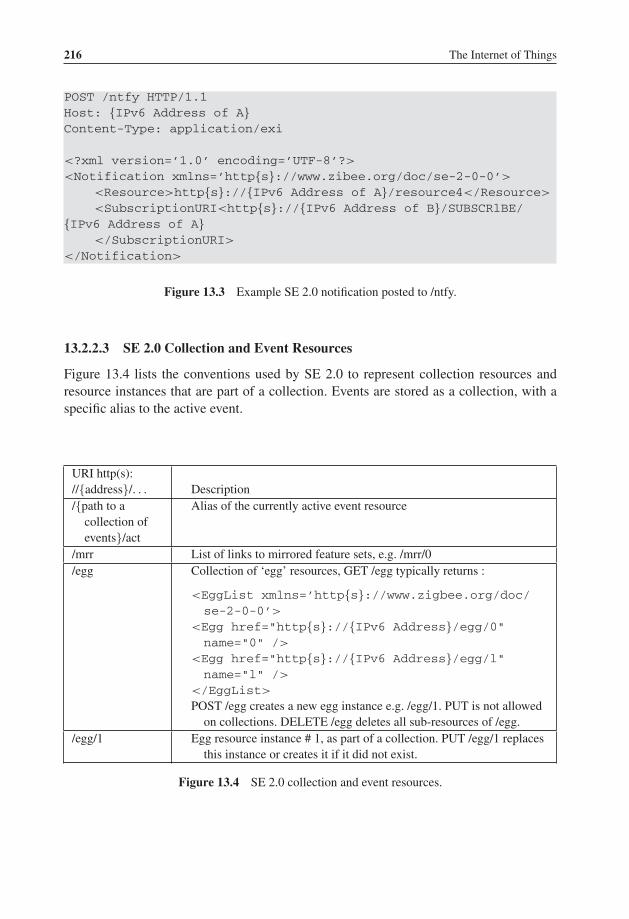
P1: TIX/XYZ P2: ABCJWST118-c13 JWST118-Hersent November 28, 2011 22:18 Printer Name: Yet to Come
216 The Internet of Things
POST /ntfy HTTP/1.1Host: {IPv6 Address of A}Content-Type: application/exi
<?xml version=’1.0’ encoding=’UTF-8’?>
<Notification xmlns=’http{s}://www.zibee.org/doc/se-2-0-0’>
<Resource>http{s}://{IPv6 Address of A}/resource4</Resource>
<SubscriptionURI<http{s}://{IPv6 Address of B}/SUBSCRlBE/{IPv6 Address of A}
</SubscriptionURI>
</Notification>
Figure 13.3 Example SE 2.0 notification posted to /ntfy.
13.2.2.3 SE 2.0 Collection and Event Resources
Figure 13.4 lists the conventions used by SE 2.0 to represent collection resources andresource instances that are part of a collection. Events are stored as a collection, with aspecific alias to the active event.
URI http(s)://{address}/. . . Description/{path to a
collection ofevents}/act
Alias of the currently active event resource
/mrr List of links to mirrored feature sets, e.g. /mrr/0/egg Collection of ‘egg’ resources, GET /egg typically returns :
<EggList xmlns=’http{s}://www.zigbee.org/doc/se-2-0-0’>
<Egg href="http{s}://{IPv6 Address}/egg/0"name="0" />
<Egg href="http{s}://{IPv6 Address}/egg/l"name="l" />
</EggList>
POST /egg creates a new egg instance e.g. /egg/1. PUT is not allowedon collections. DELETE /egg deletes all sub-resources of /egg.
/egg/1 Egg resource instance # 1, as part of a collection. PUT /egg/1 replacesthis instance or creates it if it did not exist.
Figure 13.4 SE 2.0 collection and event resources.

P1: TIX/XYZ P2: ABCJWST118-c13 JWST118-Hersent November 28, 2011 22:18 Printer Name: Yet to Come
ZigBee Smart Energy 2.0 217
13.2.2.4 Resource Discovery, /rsc
For the resolution of host names, device and resource discovery, SE 2.0uses mDNS (IETF draft-cheshire-dnsext-multicastdns) and DNS-SD (draft-cheshire-dnsext-dns-sd). DNS service discovery uses DNS PTR records mapping a<Service>.<Domain> (e.g. Test\032Server._smartenergy._tcp.local.) name to a list of<Instance>.<Service>.<Domain> names. Each <Instance>.<Service>.<Domain>
can be located by using DNS SRV records, and additional service information is stored inTXT records in key/value pair format. The URI of an Smart Energy 2.0 DeviceCapabilitiesresource is stored in the path key (e.g. path=/dcap).
The list of resources on a given host (identified by its IP address) is represented at URI/rsc, and enumerates all logical device types supported, and the URI of the related functionset (see Section 12.3). In ZigBee 1.0 terms, this is equivalent to the list of “endpoints”,each endpoint corresponding to a function set.
The list may also contain mirrored resources for other devices (e.g., sleeping or mobiledevices). The list of mirrored resources may also be found at /mrr.
13.3 Function Sets and Device Types
SE 2.0 defines a “function set” as a group of related functionalities (the equivalent of acluster in ZigBee 1.0). Each function set defines a list of REST resources and associatedtransactions, and is identified by a resource name. The resource name is used for theresource discovery mechanism.
SE 2.0 defines the following function sets:
� demand response/load control;� messaging;� confirmation;� pricing;� prepayment;� metering;� plug-in electric vehicles;� distributed energy resource;� billing;� registration;� base;� device management/configuration;� firmware download server;� firmware download client;� diagnostics and monitoring.
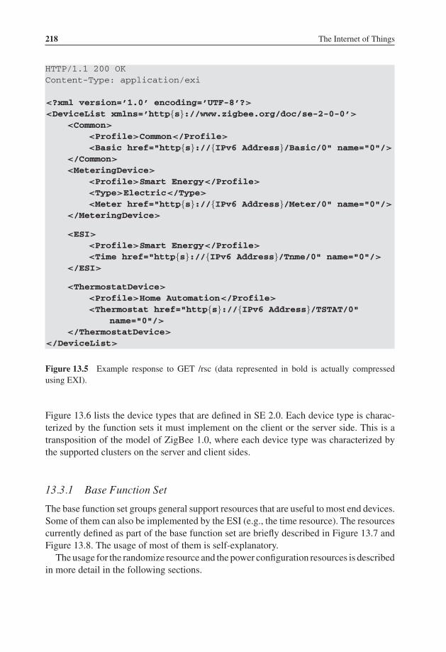
P1: TIX/XYZ P2: ABCJWST118-c13 JWST118-Hersent November 28, 2011 22:18 Printer Name: Yet to Come
218 The Internet of Things
HTTP/1.1 200 OKContent-Type: application/exi
<?xml version=’1.0’ encoding=’UTF-8’?>
<DeviceList xmlns=’http{s}://www.zigbee.org/doc/se-2-0-0’>
<Common>
<Profile>Common</Profile>
<Basic href="http{s}://{IPv6 Address}/Basic/0" name="0"/>
</Common>
<MeteringDevice>
<Profile>Smart Energy</Profile>
<Type>Electric</Type>
<Meter href="http{s}://{IPv6 Address}/Meter/0" name="0"/>
</MeteringDevice>
<ESI>
<Profile>Smart Energy</Profile>
<Time href="http{s}://{IPv6 Address}/Tnme/0" name="0"/>
</ESI>
<ThermostatDevice>
<Profile>Home Automation</Profile>
<Thermostat href="http{s}://{IPv6 Address}/TSTAT/0"name="0"/>
</ThermostatDevice>
</DeviceList>
Figure 13.5 Example response to GET /rsc (data represented in bold is actually compressedusing EXI).
Figure 13.6 lists the device types that are defined in SE 2.0. Each device type is charac-terized by the function sets it must implement on the client or the server side. This is atransposition of the model of ZigBee 1.0, where each device type was characterized bythe supported clusters on the server and client sides.
13.3.1 Base Function Set
The base function set groups general support resources that are useful to most end devices.Some of them can also be implemented by the ESI (e.g., the time resource). The resourcescurrently defined as part of the base function set are briefly described in Figure 13.7 andFigure 13.8. The usage of most of them is self-explanatory.
The usage for the randomize resource and the power configuration resources is describedin more detail in the following sections.
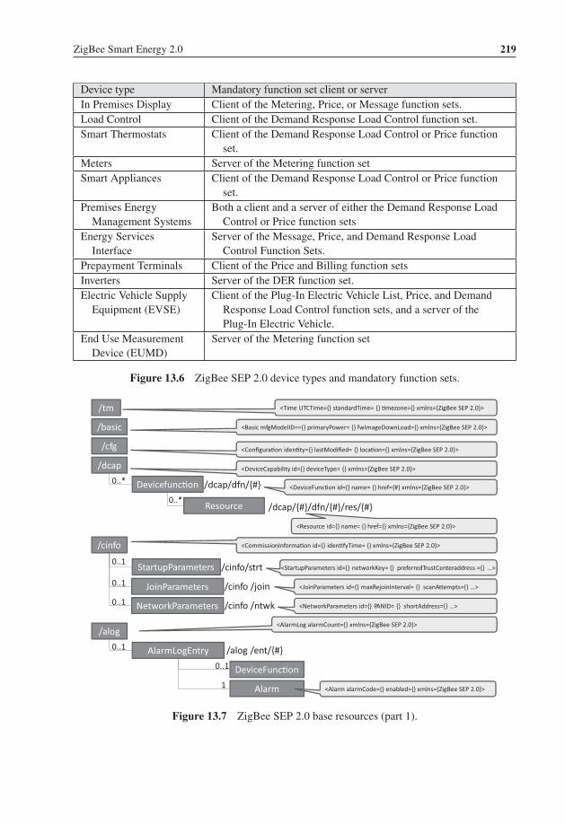
P1: TIX/XYZ P2: ABCJWST118-c13 JWST118-Hersent November 28, 2011 22:18 Printer Name: Yet to Come
ZigBee Smart Energy 2.0 219
Device type Mandatory function set client or serverIn Premises Display Client of the Metering, Price, or Message function sets.Load Control Client of the Demand Response Load Control function set.Smart Thermostats Client of the Demand Response Load Control or Price function
set.Meters Server of the Metering function setSmart Appliances Client of the Demand Response Load Control or Price function
set.Premises Energy
Management SystemsBoth a client and a server of either the Demand Response Load
Control or Price function setsEnergy Services
InterfaceServer of the Message, Price, and Demand Response Load
Control Function Sets.Prepayment Terminals Client of the Price and Billing function setsInverters Server of the DER function set.Electric Vehicle Supply
Equipment (EVSE)Client of the Plug-In Electric Vehicle List, Price, and Demand
Response Load Control function sets, and a server of thePlug-In Electric Vehicle.
End Use MeasurementDevice (EUMD)
Server of the Metering function set
Figure 13.6 ZigBee SEP 2.0 device types and mandatory function sets.
Devicefunc�on
Resource0..*
/tm
/dcap/dfn/{#}
<Time UTCTime={} standardTime= {} �mezone={} xmlns={ZigBee SEP 2.0}>
DeviceFunc�on0..1
/dcap/{#}/dfn/{#}/res/{#}
/basic <Basic mfgModelID=={} primaryPower= {} fwImageDownLoad={} xmlns={ZigBee SEP 2.0}>
/cfg <Configura�on iden�ty={} lastModified= {} loca�on={} xmlns={ZigBee SEP 2.0}>
/dcap <DeviceCapability id={} deviceType= {} xmlns={ZigBee SEP 2.0}>
0..*<DeviceFunc�on id={} name= {} href={#} xmlns={ZigBee SEP 2.0}>
<Resource id={} name= {} href={} xmlns={ZigBee SEP 2.0}>
/cinfo <CommissionInforma�on id={} iden�fyTime= {} xmlns={ZigBee SEP 2.0}>
StartupParameters /cinfo/strt0..1
JoinParameters
NetworkParameters
0..1
0..1
<StartupParameters id={} networkKey= {} preferredTrustCenteraddress ={} …>
<JoinParameters id={} maxRejoinInterval= {} scanA�empts={} …>/cinfo /join
/cinfo /ntwk <NetworkParameters id={} PANID= {} shortAddress={} …>
/alog
AlarmLogEntry0..1
Alarm1
<AlarmLog alarmCount={} xmlns={ZigBee SEP 2.0}>
/alog /ent/{#}
<Alarm alarmCode={} enabled={} xmlns={ZigBee SEP 2.0}>
Figure 13.7 ZigBee SEP 2.0 base resources (part 1).

P1: TIX/XYZ P2: ABCJWST118-c13 JWST118-Hersent November 28, 2011 22:18 Printer Name: Yet to Come
220 The Internet of Things
/pcfg <PowerConfigura�on state={} xmlns={ZigBeeSEP 2.0}>
Mains <Mains frequency=={} voltage= {} voltageDwellTripPoint={} xmlns={ZigBee SEP 2.0}>
Ba�ery <Ba�eryahrRtg={} stateOfcharge= {} loBatVAlm={} xmlns={ZigBee SEP 2.0}>
/pcfg/main
/pcfg/ba�
0..1
0..1
/rndm<Randomiza�on>
<startValue>180</startValue><endvalue>180</endvalue><method>local</method>
</Randomiza�on>
Figure 13.8 ZigBee SEP 2.0 base resources (part 2).
13.3.1.1 Randomization
Telecom service providers know the potential catastrophic effects of massive synchro-nization of client devices (see Appendix B). In order to provide a generic tool to avoidthese situations, ZigBee SE 2.0 provides a randomization mechanism that can be usedby any function set potentially affected by this problem: at present, the demand responseload control, and price function sets.
Randomization is supported through the /rndm resource (see Figure 13.8 andFigure 13.9). Depending on the service-provider policy, the implementation may relyon the effective calculation of a random value, within the specified bounds, by the device,or on a fixed random value preconfigured on each device.
<Randomization>
<startValue>180</startValue>
<endvalue>180</endvalue>
<method>local</method>
</Randomization>
Figure 13.9 ZigBee SE 2.0 randomization resource example.
13.3.1.2 Firmware Download
The firmware upload function is implemented by an upgrade client (UC), which polls,or optionally subscribes to the resources of an upgrade server (US). ZigBee SEP 2.0defines a digitally signed firmware file format similar to that already used for ZigBee1.0 over-the-air (OTA) upgrading cluster, with minor changes. Several types of files aredefined (security credential, log, configuration) and identified by a two-octet value, with0×0000-0xffbf reserved for manufacturer use (one identifier should be used per devicetype). This makes it possible to update or subscribe to changes of only certain file types(0xffff is defined as the wildcard file type).

P1: TIX/XYZ P2: ABCJWST118-c13 JWST118-Hersent November 28, 2011 22:18 Printer Name: Yet to Come
ZigBee Smart Energy 2.0 221
Loadstatus /files/loadstatus
/files
0..*<FileLoadStatus>
<File href=’�tp://{US addr}/files/all/0002.zigbee’ size=’128000’/><Ac�veVersion>00000000</Ac�veVersion><State>01</State><Offset>1024</Offset>
</FileLoadStatus>
<FileList><File href=’�tp://{US addr}/files/all/0002.zigbee’ size=’128000’/><File href=’�tp://{US addr }/files/all/0003.zigbee’ size=’128000’/>
</FileList>
<Ac�va�on><CurrentTime>2010 -03-12T00:00:00Z</CurrentTime><Ac�vateTime>2010 -03-12T00:01:00Z</Ac�vateTime>
</Ac�va�on>
/files/ac�va�on/file=…Ac�va�on
(Upgrade client)
/files (Upgrade server)
Latest /files/latest
Downloading
Figure 13.10 ZigBee SEP 2.0 firmware upload resources.
On the upgrade server, the URI/files/latest returns the list of new files targeted forthe client. The request optionally specifies the manufacturer code, file type and currentfile version. Deferred activation is supported by means of the Activation resource. Theupgrade server resources are outlined in Figure 13.10.
On the client side, the status of configuration files can be verified by reading the/files/loadstatus resource.
13.3.2 Group Enrollment
Energy service providers usually want to direct their commands (e.g., demand-responsecommands) to only a subset of all potential controlled devices. This might be to avoidsynchronization effects, to control the aggregate energy volume affected by the command,or to scope the command geographically. SE 2.0 supports these requirements by providingthe notion of a group enrollment resource.
The SE 2.0 group enrollment URI is /enrl.
<?xml version=’1.0’ encoding=’UTF-8’?>
<EnrollmentList xmlns=’http{s}://www.zigbee.org/doc/se-2-0-0’>
<EnrollGroup>
<Group>0</Group>
<Group>1</Group>
</EnrollGroup>
</EnrollmentList>
As this book was going to press, an update of the draft specification was published. Device groupenrollments are now configured as a subresource of the EndDevice resource instance on the ESI.Each group contains links to the specific function set instances applicable to the EndDeviceGroup./enrl resource is no longer used.

P1: TIX/XYZ P2: ABCJWST118-c13 JWST118-Hersent November 28, 2011 22:18 Printer Name: Yet to Come
222 The Internet of Things
1 TimeAttribute 12 = instantaneous2 DataQualifier 0=N/A3 AccumlationBehaviour 6= indicating4 FlowDirection l=Forward5 UomCategorySubclass 0=N/A6 UomCategoryIndex 8=demand7 MeasurementCategory 0=N/A8 Enumeration9 Phase 0=n/a to all phases10 Multiplier 3=kilo11 UnitOfMeasure 38=W
Figure 13.11 IEC TC57 61968 ReadingTypeID structure.
<TariffProfile href=”h�p{s}://{IPv6 Address}/PR/0/TFF”><ID>12345</ID><name>12345</name>
</TariffProfile>
<Readings><�meStamp>2010-03-17T09:00:00Z</�meStamp><value>12.35</value>
</Readings>
<MeterReading><ReadingType href=”h�p{s}://{Addr}/mtr/0/mr/0”>
<ID>12.0.6.1.0.8.0.0.0.3.38</ID><name>Instantaneous Demand</name>
</ReadingType><ReadingType href=”h�p{s}://{Addr}/mtr/0/mr/1”>
<ID>4.0.3.1.0.12.3.1.0.3.72</ID><name>Daily (24 Hour) totals</name>
</ReadingType></MeterReading>
MeterAsset
MeterReading
Status
TariffProfile
1..*
1..*
1..*
/mtr
/mtr/{#}
<MeterReading href=”h�p{s}://{Address}/mtr/0/mr”/><Status href=”h�p{s}://{Address}/mtr/0/s”/><TariffProfile href=”h�p{s}://{Address}/mtr/0/tp”/>
<MeterAsset href=” h�p{s}://{IPv6 Address}/mtr/0”><ID>101</ID><name>Electricity Meter #1</name>
</MeterAsset><MeterAsset href=” h�p{s}://{IPv6 Address}/mtr/1”>
<ID>201</ID><name>Electricity Meter #2</name>
</MeterAsset>
IntervalReading
Reading
ReadingType
1..*
1..*
1..*
/mtr/{#}/mr
kWh
/mtr/{#}/s
/mtr/{#}/tp
Ref. to tariffprofile informa�on fromPricingData service interface
Figure 13.12 ZigBee SE 2.0 meter resources.

P1: TIX/XYZ P2: ABCJWST118-c13 JWST118-Hersent November 28, 2011 22:18 Printer Name: Yet to Come
ZigBee Smart Energy 2.0 223
13.3.3 Meter
The meter structures of ZigBee SEP 2.0 have been designed in close coordination with IECTC57 61968 and captures a baseline metering functionality. SEP 2.0 does not implement,however, more advanced functions such as programmable autoreads. The structure of themetering resources is outlined in Figure 13.12.
The ReadingTypeID format is imported from IEC TC57 61968, it is a concatena-tion of 9 attributes each represented by one or two integers for a total of 11 integers(Figure 13.11). For instance the present maximum indicating forward water (m3/h) isrepresented by 15.8.6.1.0.63.0.0.0.0.121.
13.3.4 Pricing
The price resources allow utilities to publish a description of their tariff structures onan ESI. Figure 13.13 illustrates the relationships between price resources and shows the“well-known” URIs defined by SE 2.0.
The ZigBee SE 2.0 pricing resources support both time of use (ToU) pricingand consumption interval pricing, in any combination. The example of Figure 13.14,adapted from draft 0.7, shows how time-based pricing and volume-based pricingcan coexist.
PricingStructure
ServiceCategory
Tariff
ServiceSupplier
CustomerAccount
TariffProfile
Consump�onTariffInterval
TimeTariffInterval
Charge
Randomiza�on
0..1
0..*
0..*
0..*
0..*
0..*
0..*
Charge
0..*
0..1
0..1
/pr
/pr/{#}/�f /{#}
/pr/{#}
<PricingStructure xmlns=’h�p{s}://www.zigbee.org/doc/se -2-0-0’><Tariff href=”h�p{s}://{IPv6 Address}/PR/0” /><Tariff href=”h�p{s}://{IPv6 Address}/PR/1” /></PricingStructure>
<Tariff xmlns=’h�p{s}://www.zigbee.org/…/2-0-0’><ServiceSupplier/><name>Green Rate</name><startDate>2010-03-12T00:00:01Z</startDate>
<TariffProfile href=”h�p{s}://{Address}/PR/0/TFF” /></Tariff>
Figure 13.13 ZigBee SE 2.0 pricing resources.

P1: TIX/XYZ P2: ABCJWST118-c13 JWST118-Hersent November 28, 2011 22:18 Printer Name: Yet to Come
224 The Internet of Things
<!-- Midnight to 8:00am --><?xml version=’1.0’ encoding=’UTF-8’?><TimeTariffIntervalxmlns=’h�p{s}://www.zigbee.org/doc/se-2-0-0’>
<startDateTime>2010-03-12T00:00:01Z</startDateTime><!-- 0 to 100 kWh --><Consump�onTariffInterval>
<startValue>0</startValue><Charge>
<fixedPor�on><value>0.05</value><monetaryUnit>USD</monetaryUnit>
</fixedPor�on></Charge>
</Consump�onTariffInterval><!-- > 100 kWh --><Consump�onTariffInterval>
<startValue>100</startValue><Charge>
<fixedPor�on><value>0.07</value><monetaryUnit>USD</monetaryUnit>
</fixedPor�on></Charge>
</Consump�onTariffInterval><Randomiza�on>
<flag>TRUE</flag><type>Start</type>
</Randomiza�on><Randomiza�on>
<flag>TRUE</flag><type>End</type>
</Randomiza�on></TimeTariffInterval>
This tariff interval implicitlyends at the startDate�me of the next �meTariffInterval
This consump�on intervalimplicitly ends at the startValue of the nextconsump�on interval
Figure 13.14 Example TimeTariffInterval resource.
13.3.5 Demand Response and Load Control Function Set
The clients of the DR/LC function set are typically smart thermostats or any device thatsupports load control. The server side is typically the ESI and implements the followingresources (see Figure 13.15):
– /dr : a collection of DemandResponseProgram collections;– /dr/{#} : a specific DemandResponseProgram collection resource;– /dr/{#}/nm : a specific DemandResponseProgram name attribute resource;– /dr/{#}/edc : a collection of EndDevicesControls;– /dr/{#}/edc /{#} : a specific EndDevicesControl resource;– /dr/{#}/edc /act : the active EndDevicesControl resource.

P1: TIX/XYZ P2: ABCJWST118-c13 JWST118-Hersent November 28, 2011 22:18 Printer Name: Yet to Come
ZigBee Smart Energy 2.0 225
DemandResponseProgram
EndDeviceControl
DutyCycle
EndDeviceGroup
HANAsset
Offset
Randomiza�on
SetPoint
Status
0..*
0..*
0..*
0..*
0..*
0..*
0..*
0..1
Figure 13.15 ZigBee SE 2.0 DR/LC server resources.
The EndDeviceControl resource contains or points to all the information required by aclient to implement a particular dr/lc event for a period of time.
In addition to the attributes listed in Figure 13.16, each EndDeviceControl resourcemay also contain the subresources listed in Figure 13.17.
DR/LC attributes DescriptionProgramLevel (integer) Level of a demand response program request, where 0=emergency.drProgramMandatory(boolean)
Whether a demand response program request is mandatory
duration (Minutes) Event duration (end - start)href (anyURI) Hypertext reference pointing to a URIID (string) Object identifiername (string) Name of the EndDeviceControl resourcescheduledInterval(DateTimeInterval)
(if control has scheduled duration) Date and time interval the controlhas been scheduled to execute within.
type (string) Type
Figure 13.16 EndDeviceControl attributes.

P1: TIX/XYZ P2: ABCJWST118-c13 JWST118-Hersent November 28, 2011 22:18 Printer Name: Yet to Come
226 The Internet of Things
Sub-Resource Sub-Resource attributesDutyCycle – name (string): Duty cycle name
– normalValue (PerCent): Duty cycle value such as 80%– state (string): State such as on or off
EndDeviceGroup – groupAddress (integer) : Address of this end device group.– href (anyURI) : Hypertext reference pointing to a URI– ID (object identifier)
HANAsset – category (string): Utility-specific categorization of this document.– href (anyURI) : Hypertext reference pointing to a URI– ID (string) : HAN asset identifier
Offset : Offsetsuch as coolingor heatingoffset
– name (string)– normalValue (PerCent)– Offset as per cent– type (string)– Offset type– value (string) : offset value
Randomization :Randomizationfor start or endof an event
– endValue (unsignedInt) : End randomization value in SEP UTCTimeformat such 300 for 5 minutes
– flag (boolean) : Randomization or not– href (anyURI) : Hypertext reference pointing to a URI– ID (string): Identifier– method (string)– Local (maximum) or static randomization– name (string) : Randomization name– startValue (unsignedInt) : Start randomization value in SEP UTCTime
format such 300 for 5 min– type (string) : Randomization type (start or end randomization)
SetPoint : ASetPoint is ananalog controlused forsupervisorycontrol.
– maxValue (float) : Normal value range maximum for any of theControl.value. Used for scaling, e.g. in bar graphs.
– minValue (float) : Normal value range minimum for any of theControl.value. Used for scaling, e.g. in bar graphs.
– name attribute (string) : Name of an attribute.– normalValue (float) : Normal value for Control.value e.g. used for
percentage scaling– value (float) : Value in type of float
Status: Currentstatusinformationrelevant to anentity.
– dateTime (unsignedInt) : Date and time for which status ‘value’ applies.– href (anyURI) : Hypertext reference pointing to a URI– reason: Reason code or explanation for why an object went to the
current status ‘Value’.– value (string) : Value in string
Figure 13.17 DR/LC EndDeviceControl subresources.

P1: TIX/XYZ P2: ABCJWST118-c13 JWST118-Hersent November 28, 2011 22:18 Printer Name: Yet to Come
ZigBee Smart Energy 2.0 227
The DR client would typically send the following request to the ESI:
GET /esi HTTP/1.1Host: {IPv6 Address}
The server would respond:
HTTP/1.1 200 OKContent-Type: application/exi<?xml version=‘‘1.0’’ encoding=‘‘UTF-8’’?>
<EndDeviceControl href=‘‘ http{s}://{IPv6 Address}/dr/0/edc/0’’>
<ID>101</ID>
<Randomization>
<flag>TRUE</flag>
<type>Start</type>
</Randomization>
<Randomization>
<flag>TRUE</flag>
<type>End</type>
</Randomization>
</EndDeviceControl>
13.3.6 Distributed Energy Resources
The ZigBee S2.0 SEP resources that model distributed energy resources are outlined inFigure 13.18.
The power-generation curve is perhaps the most important piece of information from autility perspective. This resource stores the stepwise linear approximation of the power-generation curve, an example is given in Figure 13.19.
The DERstatus object contains a description of the operational state of the generatingunit, such as “starting up”, the number of times the generator has been started since thelast counter reset, and the total operation time of the generator since the last counter reset.
The DERcontrol object allows a utility to offset the production level to a certainpercentage, and includes options to randomize such commands.
13.3.7 Plug-In Electric Vehicle
One of the priority action plans (PAP 111) of the US National Institute of Standards andTechnology (NIST) Smart Grid Interoperability Panel (SGIP) is to design common objectmodels for electric transportation. PAP11 formulates the issue as follows:
1 http://collaborate.nist.gov/twiki-sggrid/bin/view/SmartGrid/PAP11PEV.

P1: TIX/XYZ P2: ABCJWST118-c13 JWST118-Hersent November 28, 2011 22:18 Printer Name: Yet to Come
228 The Internet of Things
DistributedGenera�ngUnit
Ba�ery
DERControl
DERstatus
0..*
0..1
0..*
/dgu
/dgu/{#}
<DistributedGenera�ngUnit><ID>101</mRID><name>Solar Panel #1</name><Ba�ery href=”h�p{s}://{Addr}/dgu/0/b”/><EndDeviceGroup
href=”h�p{s}://{Addr}/dgu/0/edg”/><HANAsset href=”h�p{s}://{Addr}/dgu/0/ha”/><PowerGenera�onCurve
href=”h�p{s}://{Addr}/dgu/0/pgc”/><Status>href=”h�p{s}://{Addr}/dgu/0/s”/>
<TimeSchedule>href=”h�p{s}://{Addr}/dgu/0/ts”/></DistributedGenera�ngUnit>
<DistributedGenera�ngUnit href=”h�p{s}://{Addr}/dgu/0”><ID>101</ID><name>Solar Panel #1</name>
</DistributedGenera�ngUnit><DistributedGenera�ngUnit href=”h�p{s}://{Addr}/dgu/1”>
<ID>301</ID><name>Wind Turbine #1</name>
</DistributedGenera�ngUnit>
Charger
Ba�eryStatus
0..1
0..*
/dgu/{#}/b/{#}
EndDeviceGroup0..1
PowerGenera�onCurve0..*
TimeSchedule0..*
/dgu/{#}/pgc/{#}
/dgu/{#}/edg/{#}
/dgu/{#}/s/{#}
/dgu/{#}/ts/{#}
/dgu/{#}/drp/{#}
HANAsset0..1 /dgu/{#}/ha/
Figure 13.18 ZigBee 2.0 SEP distributed energy resources data model.
<PowerGenerationCurve href="http{s}://{IPv6 Address}/dgu/0/pgc/0">
<curveType></curveType>
<description></description>
<ID></ID>
<xUnit>s</xUnit>
<y1Unit>W</y1Unit>
<CurveData>
<xvalue>1.0</xvalue>
<y1value>12.34</y1value>
</CurveData>
<CurveData>
<xvalue>2.0</xvalue>
<y1value>42.34</y1value>
</CurveData>
<CurveData>
<xvalue>3.0</xvalue>
<y1value>72.34</y1value>
</CurveData>
</PowerGenerationCurve>
Figure 13.19 ZigBee 2.0 SEP PowerGenerationCurve example.

P1: TIX/XYZ P2: ABCJWST118-c13 JWST118-Hersent November 28, 2011 22:18 Printer Name: Yet to Come
ZigBee Smart Energy 2.0 229
The introduction of mobile plug-in electric vehicles (PEVs) to the grid creates some in-teroperability challenges around exchanging price, demand response (DR), and settlementinformation. The impact of PEVs on the grid is expected to be significant, and the abilityto control the charging profiles through price or direct control, the need for cyber security(including appropriate privacy), the issues of safety, the possibility of allowing customers tosell PEV electricity back into the grid, and complexity of providing fair settlement to every-one in the value chain when vehicles charge away from their home base, requires commonobject models to manage all these aspects.
As of March 2011, no firm decision had been made by the SGIP governing board toadopt the ZigBee SE 2.0 information model (repackaged as SAE J2847/1) as a standard,however, it was the most likely candidate to be adopted during the ongoing standardizationprocess to be held within the SGIP Vehicle to Grid (V2G) working group,2 and withinIEC TC 57 (ZigBee SE 2.0 PEV and DER information model are designed as an extensionof the common information model, or CIM, defined in IEC 61968 and IEC 61850). Formore background information on EV charging, refer to Chapter 6.
The structure of the ZigBee 2.0 SEP resources that compose the PEV function set isoutlined in Figure 13.20.
The ElectricVehicle object is characterized by the objects listed in Figure 13.20, andfollowing attributes:
– ID: a string;– odometerReadDateTime: an unsigned integer indicating the date of the odometer3
reading;– odometerReading: a string indicating the actual reading;– status: an indicator of the status of the battery, which includes indicators for over and
under charge conditions, and a per cent indicator of the state of charge.
The battery object indicates the battery technology (batTyp attribute), Ah capacity ratingof the battery (ahrRtg), and battery nominal voltage.
A specific charger resource is designed to retrieve the battery charge information:http{s}://{IPv6 Address}/pev/{#}/bttr/{#}/ct where “ct” stands for “charge transaction”.The charger resource indicates, among other things, the active power charge rate (reChaRteattribute) of the battery, and the charging schedule (start and end time).
The battery status subresource: http{s}://{IPv6 Address}/pev/{#}/bttr/{#}/s includesindicators for over- and undercharge conditions, and a per cent indicator of the state ofcharge for the specific battery.
The DemandResponseProgram collection contains a list of pointers to DemandRespon-sePrograms, identified by their ID (the actual DemandResponseProgram resource resideson the ESI), and applying to this PEV.
2 http://collaborate.nist.gov/twiki-sggrid/bin/view/SmartGrid/V2G.3 “An odometer indicates distance traveled by a car or other vehicle” (Wikipedia).

P1: TIX/XYZ P2: ABCJWST118-c13 JWST118-Hersent November 28, 2011 22:18 Printer Name: Yet to Come
230 The Internet of Things
ElectricVehicle
Ba�ery
DemandResponseProgram
DistributedGenera�ngUnit
0..*
0..*
0..*
/pev
/pev/{#}
<ElectricVehicle><Ba�er href=”h�p{s}://{Addr}/pev/0/b�r”/><DemandResponseProgram
href=”h�p{s}://{Addr}/pev/0/drp”/><DistributedGenera�ngUnit
href=”h�p{s}://{Addr}/pev/0/dgu”/><EndDeviceGroup
href=”h�p{s}://{Addr}/pev/0/edg”/><Loca�on href=”h�p{s}://{Addr}/pev/0/loc”/>
<MeterAssethref=”h�p{s}://{Addr}/pev/0/mtr”/>
<TariffProfile href=”h�p{s}://{Addr}/pev/0/tp”/></ElectricVehicle>
<ElectricVehicle href=”h�p{s}://{IPv6 Address}/pev/0”><ID>101</ID>
</ElectricVehicle><ElectricVehicle href=”h�p{s}://{IPv6 Address}/pev/1”>
<ID>201</ID></ElectricVehicle>
Charger
Ba�eryStatus
0..1
0..*
/pev/{#}/b�r/{#}
endDeviceGroup0..*
Loca�on0..1
MeterAsset0..1
TarifProfile0..*
/pev/{#}/loc/{#}
/pev/{#}/edg/{#}
/pev/{#}/dgu/{#}
/pev/{#}/mtr/
/pev/{#}/tp/{#}
/pev/{#}/drp/{#}
Figure 13.20 ZigBee 2.0 SEP PEV resources.
13.3.8 Messaging
The messaging function set uses two types of resources:
– TextMessages (see Figure 13.21) is typically implemented in the ESI and mustbe polled or subscribed to by the clients. The resource URI http{s}://{serverIPv6 Address}/msg/ provides access to a collection of message collections. In-dividual messages are accessed by their individual URIs http{s}://{server IPv6Address}/msg/{#}/txt/{#}. The structure of each TextMessage, as illustrated on Figure13.21, enables the ESI to display each message to only certain groups of devices, orto certain device types, at during certain periods of time. Each message may request aconfirmation.
– Confirmations. That resource is implemented (or mirrored to a parent device) byin premises displays that are capable of message confirmation. The resource URIhttp{s}://{IPv6 Address}/rsp/ provides access to a collection of responses. The struc-ture of the confirmation resource includes the confirmed message ID and a time stamp.It can also be used to confirm prices or billing.
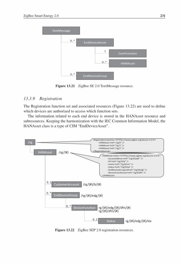
P1: TIX/XYZ P2: ABCJWST118-c13 JWST118-Hersent November 28, 2011 22:18 Printer Name: Yet to Come
ZigBee Smart Energy 2.0 231
TextMessage
EndDeviceAsset
EndDeviceGroup
ComFunc�on
HANAsset
0..*
0..*
0..*
1
Figure 13.21 ZigBee SE 2.0 TextMessage resource.
13.3.9 Registration
The Registration function set and associated resources (Figure 13.22) are used to definewhich devices are authorized to access which function sets.
The information related to each end device is stored in the HANAsset resource andsubresources. Keeping the harmonization with the IEC Common Information Model, theHANAsset class is a type of CIM “EndDeviceAsset”.
HANAsset
CustomerAccount
EndDeviceGroup
0..1
0..*
/rg
/rg/{#}<HANAsset xmlns=’HTTP{s}://www.zigbee.org/doc/se-2-0-0’>
<accessAddress href=”/rg/0/addr” /><ID href=”/rg/0/id” /><name href=”/rg/0/nm” /><status href=”/rg/0/sta” /><EndDeviceGroupListhref=”/rg/0/edg” /><DeviceFunc�onList href=”/rg/0/dfn” />
</HANAsset>
<Registra�onListxmlns=’HTTP{s}://www.zigbee.org/doc/se-2-0-0’><HANAsset href=”/rg/0” /><HANAsset href=”/rg/1” /><HANAsset href=”/rg/2” />
</Registra�onList>
DeviceFunc�on
Status
0..*
0..1
/rg/{#}/b/{#}
/rg/{#}/edg/{#}
rg/{#}/edg/{#}/dfn/{#}
rg/{#}/edg/{#}/sta
rg/{#}/dfn/{#}
Figure 13.22 ZigBee SEP 2.0 registration resources.

P1: TIX/XYZ P2: ABCJWST118-c13 JWST118-Hersent November 28, 2011 22:18 Printer Name: Yet to Come
232 The Internet of Things
The DeviceFunctions list the FunctionSets that the device has been granted accessto prior to registration, or has requested access to through the registration process. The“status” of the DeviceFunction registration reflects whether access has been grantedor if the request is still pending. An end device may declare its membership in one ofseveral EndDeviceGroups. The DeviceFunctions that are declared as subresources of anEndDeviceGroup are function sets that can be accessed by all members of the group.
A number of shortcut REST URIs have been defined to access HANAsset attributes,which are listed in Figure 13.23.
Note: As this book was going to press, an update of the draft specification was published. Theregistration of each device is now materialized by an instance of EndDevice resource on the serverto which the device registered, e.g. /edev/1 instead of rg/1.
13.4 ZigBee SE 2.0 Security
13.4.1 Certificates
A device certificate is installed during manufacturing on each SE device, and is notexpected to change during the lifetime of the device (as long as the network ID, e.g.,EUI-64, of the device does not change).
An operational certificate is used to secure a given session or relationship. The regis-tration server is used to perform registration and grants an operational certificate.
13.4.2 IP Level Security
The first thing an SE 2.0 device needs to do is to access the network.Each layer 2 technology defines specific means for the authentication of new nodes,
which is problematic for technologies that want to remain layer 2 agnostic, like SE2.0. PANA (RFC 5191) solves this issue by defining a protocol that allows clients toauthenticate themselves to the access network using IP protocols. The PANA client(PaC) is configured with an IPv6 address, and exchanges IP UDP PANA authenticationmessages with the PANA authentication agent (PAA). The network enforcement point(EP) is supposed to let unauthenticated nodes to communicate with the IP address of thePAA : it may be collocated with the PAA, or it acts as a PANA relay element (PRE).Communication between the PaC and the PRE uses UDP over port 716. Typically, on a802.15.4 radio network, the PRE would be the parent node (PN) and the joining nodewould be the PaC, both would be using their link local IPv6 addresses (see Chapter 1 formore information on 802.15.4).
Upon successful authentication, the PaC is granted broader network access possibly bya new IP address assignment (typically, add a IPv6 global address using the prefix obtainedduring earlier IPv6 router discovery), by enforcement points changing filtering rules for

P1: TIX/XYZ P2: ABCJWST118-c13 JWST118-Hersent November 28, 2011 22:18 Printer Name: Yet to Come
ZigBee Smart Energy 2.0 233
/rg/{#}/addr Access address for a specific HANAsset object. E.g. :<HANAsset accessAddress={Addr} xmlns=’HTTP{s}://www.zigbee.org/doc/se-2-0-0’ />
/rg/{#}/id unique resource id for a specific HANAsset object./rg/{#}/nm name of a specific HANAsset object E.g:
<HANAsset name="Device0" xmlns=’HTTP{s}://www.zigbee.org/doc/se-2-0-0’ />
/rg/{#}/sta status value for a specific HANAsset object./rg/{#}/edg is a collection of EndDeviceGroup objects. E.g.:
<EndDeviceGroupList xmlns=’HTTP{s}://www.zigbee.org/doc/se-2-0-0’>
<EndDeviceGroup href="/rg/0/edg/0" />
<EndDeviceGroup href="/rg/0/edg/l" />
</EndDeviceGroupList>
/rg/{#}/edg/{#} specific EndDeviceGroup object./rg/{#}/edg/{#}/addr Group address of a specific EndDeviceGroup object.
<EndDeviceGroup groupAddress={IPv6Address} xmlns=’ HTTP{s}://{ZigBee SEP}’/>
/rg/{#}/edg/{#}/id unique resource id for a specific EndDeviceGroup object./rg/{#}/edg/{#}/dfn Collection of DeviceFunction objects associated with a specific
EndDeviceGroup object.<DeviceFunctionList xmlns=’HTTP{s}://www.zigbee.org/doc/se-2-0-0’>
<DeviceFunction href="/rg/0/edg/0/dfn/0" />
<DeviceFunction href="/rg/0/edg/0/dfn/l" />
</DeviceFunctionList>
/rg/{#}/edg/{#}/dfn/{#} specific DeviceFunction object associated with anEndDeviceGroup
/rg/{#}/edg/{#}/dfn/{#}/id unique resource id for a specific DeviceFunction objectassociated with an EndDeviceGroup.
/rg/{#}/edg/{#}/dfn/{#}/id unique resource id for a specific DeviceFunction objectassociated with an EndDeviceGroup.
/rg/{#}/edg/{#}/dfn/{#}/nm name of a specific DeviceFunction object associated with anEndDeviceGroup.
/rg/{#}/edg/{#}/dfn/{#}/sta Registration status for a specific HANAsset, DeviceFunction,and EndDeviceGroup.
Figure 13.23 ZigBee SEP 2.0 registration resource URIs.

P1: TIX/XYZ P2: ABCJWST118-c13 JWST118-Hersent November 28, 2011 22:18 Printer Name: Yet to Come
234 The Internet of Things
L2 securednetwork
PANA PaC
Node willing to access the secured network
EAP peer
TLS client side
PANA PAA
EAP authen�cator
TLS server side
Network Enforcement
point
Op�onalSecure tunnel
PANA-client-ini�a�on
PANA-auth-request
PANA-auth-answer
PANA-auth-request
PANA-auth-answer
Authen�ca�on agent
Figure 13.24 Overview of PANA.
the same IP address, or in the specific case of 802.15.4 by obtaining the network key.Extensions to PANA are currently being introduced to support such group key distribution(draft-ohba-pana-keywrap-02 as of March 2011).
Other than that, PANA simply encapsulates EAP payload, which enables use of anyauthentication method supported by EAP. Figure 13.24 illustrates the security stack usedto access the network, and the use of PANA.
Integrity protection of messages between the PaC and PAA is possible as soon as EAPexchanges have generated a secure association (SA) shared key. In addition PANA canestablish an optional IPsec tunnel to the PAA if the layer two is not secure and encryptionneeds to be provided.
ZigBee SE 2.0 uses EAP-TLS (RFC 5216), an EAP transport method for trans-port layer security (TLS). It uses TLS 1.2 (RFC 5246), and mandates support forthe cipher suites TLS_PSK_WITH_AES_128_CCM_8 and TLS_ECDHE_ECDSA_WITH_AES_128_CCM_8. The AES-CCM cipher is implemented in many 802.15.4chipsets in hardware. The standard TLS handshake is used to provide mutualauthentication and to derive a shared security association.
The ZigBee authentication server manages incoming EAP-TLS transactions fromjoining nodes, performs network authentication and controls network access. It is typically

P1: TIX/XYZ P2: ABCJWST118-c13 JWST118-Hersent November 28, 2011 22:18 Printer Name: Yet to Come
ZigBee Smart Energy 2.0 235
hosted by the ESI. Its functional role is roughly equivalent to that of the application trustcenter in ZigBee 1.0.
13.4.3 Application-Level Security
13.4.3.1 Registration
Once the device is able to communicate to other nodes on the IP network, it still needs toregister to the utility or service provider registration server (e.g., the ESI) in order to beable to access the service provider SE 2.0 resources.
The device authenticates with the registration server using TLS handshake based ondevice certificates, and the registration server grants one or more operational certificates tothe device (using the TLS record protocol): one operational certificate is associated to thedevice, and operational certificates are associated to individual resources on the device.At the application level, ZigBee SE 2.0 uses TLS cipher suites TLS_DHE_RSA_WITH_AES_128_GCM_SHA256 and TLS_ECDHE_ECDSA_WITH _1854 AES_128_GCM_SHA256, and X.509v3 certificates. A device may register with multipleregistration servers (e.g., multiple utilities or service providers).
13.4.3.2 Authorization Server, ACLs
Any device that contains protected resources must also implement the authorizationserver function: it authenticates the client requesting access to the resource using TLSand the operational certificates, and then uses TLS negotiation to establish a securetunnel. Therefore, in addition to native local network security, ZigBee SE 2.0 providesapplication-level secure tunnels. These secure tunnels are specific to each set of operationalcertificates, therefore to each utility registration: multiple utilities may securely share thesame SE 2.0 network. Once the identity of the client has been asserted, the authorizationserver then uses application-defined ACLs to restrict access to the protected resourcesaccording to its security policy.
Privilege DescriptionGET allowed to perform the GET method on the resourcePUT allowed to perform the PUT method on the resourcePOST allowed to perform the POST method on the resourceDELETE allowed to perform the DELETE method on the resourceGET_ACL allowed to perform the GET method on the acl subresourcePUT_ACL allowed to perform the PUT method on the acl subresourcePOST_ACL allowed to perform the POST method on the acl subresourceDELETE_ACL allowed to perform the DELETE method on the acl subresource
Figure 13.25 ACL privileges defined in ZigBee SE 2.0.

P1: TIX/XYZ P2: ABCJWST118-c13 JWST118-Hersent November 28, 2011 22:18 Printer Name: Yet to Come
236 The Internet of Things
<AccessControlList xmlns=’http{s}://www.zigbee.org/doc/se-2-0-0’>
<Grant>
<ID>{IPv6 Address}</ID>
<Privilege>GET_ACL</Privilege>
</Grant>
<Grant>
<ID>{IPv6 Address2}</ID>
<Privilege>GET</Privileg>
<Privilege>PUT</Privilege>
<Privilege>POST</Privilege>
<Privilege>DELETE</Privilege>
<Privilege>GET_ACL</Privilege>
<Privilege>PUT_ACL</Privilege>
<Privilege>POST_ACL</Privilege>
<Privilege>DELETE_ACL</Privilege>
</Grant>
<!-- Grant GET Access to ULAs -->
<Grant>
<ID>fc00: :/7</ID>
<Privilege>GET</Privilege>
</Grant>
</AccessControlList>
Figure 13.26 Example ZigBee SE 2.0 ACL.
SE 2.0 ACLs are designed as white lists: access to a resource via a REST methodis not granted unless an ACL explicitly allows it. The ACL of a resource is defined assubresource //{host address}/{resource}/acl, and lists which privileges are granted toeach client host (see Figure 13.25).
An example ACL resource is provided in Figure 13.26.

P1: TIX/XYZ P2: ABCJWST118-c14 JWST118-Hersent November 26, 2011 17:45 Printer Name: Yet to Come
14The ETSI M2M Architecture
14.1 Introduction to ETSI TC M2M
At present, there are about 50 to 70 billion “machines” in the world, about 1% of which areconnected to a communication network. There is obviously an enormous growth potentialfor M2M, but the transition from current midscale M2M applications (about 500 000devices) to the next level (applications managing tens of millions of devices) will requirenew standards.
While current M2M standards address the transport level, and client to server commu-nication protocols, the future “Internet of Things” will require a system-level architecture:
– Enabling application developers to focus on functionality, not lower-level tasks likenetwork access control, authentication or routing;
– Enabling any application to read or control any sensor, under control of a horizontalsecurity framework;
– Providing network-based services, such as data publication and subscription.
In order to achieve these goals, common functions and network elements need to beidentified and standardized at part of the M2M infrastructure: the ETSI M2M technicalcommittee was created in January 2009 at the request of many telecom operators to createa standard system-level architecture for mass-scale M2M. ETSI TC M2M does not addressone domain in particular; on the contrary, its ambition is to become the common backboneof all mass-scale M2M applications. The following domains are explicitly covered:
– Security/serenity: surveillance applications, alarms, object/people tracking;– Transportation: fleet management, road safety;– Health care: personal security, e-health;– Smart energy: measurement, provisioning and billing of utilities;– Supply and provisioning: freight supply and distribution monitoring, vending machines;– City automation: public lighting management, waste management;– Manufacturing: production chain monitoring and automation.
The Internet of Things: Key Applications and Protocols, First Edition.Olivier Hersent, David Boswarthick and Omar Elloumi.© 2012 John Wiley & Sons, Ltd. Published 2012 by John Wiley & Sons, Ltd.

P1: TIX/XYZ P2: ABCJWST118-c14 JWST118-Hersent November 26, 2011 17:45 Printer Name: Yet to Come
238 The Internet of Things
As for all recent automation protocols, the ETSI M2M architecture is resource centric andadopts the RESTful style (refer to Section 13.1 for more details on REST). As usual, thefour basic verbs of REST (create, read, update, delete) are complemented at the functionallevel by execute, subscribe and notify primitives, which are implemented, at a lower level,by helper resources manipulated by the CRUD verbs. See Section 14.3.6 for example.
We expect ETSI M2M to become the system-level architecture of the Internet of Things,much in the same way as GSM or UMTS (also from ETSI) have become the dominantsystem-level architectures for mobile communications.
ETSI M2M does not aim at replacing existing standard or proprietary automationprotocols, such as those described in the other chapters of this book. It aims at integratingall of these protocols into a common architecture, facilitating access to any of these verticalprotocols and networks from any hosted service, in an operator-controlled way. Thecompanion book “M2M Communications: A Systems Approach” (David Boswarthick,Omar Elloumi, Olivier Hersent) describes ETSI M2M general architecture in more details.In this chapter we will just give an overview of ETSI M2M architecture, and explain inmore detail how ETSI M2M can integrate existing automation and metering protocols,using the example of ZigBee 1.0, DLMS and C.12.
14.2 System Architecture
14.2.1 High-Level Architecture
The ETSI M2M functional architecture is presented in ETSI TS 102 690. The ETSI M2Msystem architecture separates the M2M device domain and the network and applicationsdomain (Figure 14.1):
– The device domain is composed of M2M devices and M2M gateways. ETSI M2Mdevices can connect to the M2M network domain directly (D’ devices) or via M2Mgateways acting as a network proxy (D devices). M2M gateways can be cascaded, oroperate in parallel mode (e.g. for redundancy purposes).
– The network and applications domain comprises:� The access and transport network (e.g., an xDSL access network and an IP transport
network).� The M2M core, which itself is composed of:
� a Core network (which provides IP connectivity, service and network control func-tions, network to network interconnect and roaming support); and
� M2M service capabilities, the functional modules implementing the M2M functionsshared by multiple applications through open interfaces.
� The M2M applications that run the M2M service logic and use the M2M servicecapabilities. The ETSI M2M architecture supports multiagent applications, whichcan have components running in the end devices (device application or DA), in thegateways (gateway application or GA) and in the network (network application orNA).

P1: TIX/XYZ P2: ABCJWST118-c14 JWST118-Hersent November 26, 2011 17:45 Printer Name: Yet to Come
The ETSI M2M Architecture 239
M2M gateway
M2M applica�ons
M2M service capabili�es
M2M devices
M2M applica�ons
M2M service capabili�es
M2M device
M2M area network
M2M applica�ons
M2M core network (e.g. 3GPP, TISPAN)
M2M access network (e.g. xDSL)
M2M core
M2M service capabili�es
M2M management
func�ons
Network management
func�ons
mIa
dIa
dIa
mIdmId
Figure 14.1 ETSI M2M high-level architecture.
� The network management functions address the access, transport and core networkprovisioning and supervision.
� The M2M management functions provide the services required for M2M servicebootstrapping (M2M service bootstrap function or MSBF), and M2M security (M2Mauthentication server or MAS).
14.2.2 Reference Points
TS 102-690 defines three reference points:
– mIa between a M2M Network Application (NA) and the M2M service capabilities in thenetworks and applications domain. It provides registration and authorization primitivesfor the NA, service session management (event reporting or streaming sessions), andread/write/execute/subscribe/notify primitives for objects or groups of objects residingin M2M devices or gateways, as well as group objects managed by the network-domaincapabilities.
– dIa between:
(a) a device application (DA) and M2M service capabilities in the same M2M deviceor in a M2M gateway;
(b) a gateway application (GA) and M2M service capabilities in the same M2Mgateway.

P1: TIX/XYZ P2: ABCJWST118-c14 JWST118-Hersent November 26, 2011 17:45 Printer Name: Yet to Come
240 The Internet of Things
GAE This function registers gateway applications and is the single contact point forgateway applications via interface dla, it hides the service capabilities topologyand performs routing towards capabilities.
GGC Manages the secure transport session establishment and policing according tothe messages service class, using GSEC to retrieve session keys. Performsrouting between Service Capabilities and the NGC Domain over interface mld.
GRAR Provides a network storage capability for state associated to named M2Mdevices and handles subscriptions to state changes. Key information itemsinclude routable addresses or reachability status. The GRAR also acts as agroup manager for M2M devices.
GCS The GCS is the network selection function when the core network is reachablevia several alternative access networks or when the gateway owns severalroutable addresses, according to the service class of the messages to be routedor other policies. It also provides alternative network or communication serviceselection in case of failures.
GREM Acts as a management proxy for the NREM.GSEC Implements key management, service layer registration, session key
management.GTM Optional transaction management.
Figure 14.2 Gateway capabilities.
dIa provides registration and authorization primitives for DAs and GAs to the de-vice/gateway, service session management (event reporting or streaming sessions), andread/write/execute/subscribe/notify primitives for objects or groups of objects residingin M2M devices or gateways, as well as group objects managed by the device/gatewaycapabilities.
– mId between an M2M device or M2M gateway and the M2M service capabilitiesin the network and applications domain. mId provides registration and authorizationprimitives for DAs and GAs to the M2M core, service session management (eventreporting or streaming sessions), and read/write/execute/subscribe/notify primitives forobjects or groups of objects residing in M2M devices or gateways, as well as groupobjects managed by the devices, gateways or in the network core capabilities.
TS 102 921 “machine-to-machine communications (M2M); mIa, dIa and mId interfaces”specifies the actual implementation of these interfaces over several protocol bindings,currently HTTP and CoAP.
14.2.3 Service Capabilities
The service capabilities can reside in the end device (in the acronyms below x=D fordevice), in the gateway (x=G, Figure 14.2), or in the network (x=N, Figure 14.3). Atpresent, the following M2M service capabilities have been defined:

P1: TIX/XYZ P2: ABCJWST118-c14 JWST118-Hersent November 26, 2011 17:45 Printer Name: Yet to Come
The ETSI M2M Architecture 241
� application enablement (xAE);� generic communication (xGC);� reachability, addressing and repository (xRAR);� communication selection (xCS);� remote entity management (xREM);� security (xSEC);� history and data retention (xHDR);� transaction management (xTM);� compensation broker (xCB);� telco operator exposure (xTOE);� interworking proxy (xIP).
Figure 14.4 illustrates the role of service capabilities in the overall ETSI M2M archi-tecture.
NAE This function registers network applications and is the single contact point fornetwork applications via interface mla, it hides the service capabilitiestopology and performs routing towards capabilities.
NGC Manages the secure transport session establishment and policing according tothe messages service class, using NSEC to retrieve session keys.Performsrouting between M2M Devices, M2M Gateways, Service Capabilities andM2M Application residing in the Network and Applications Domain. Itsupports unicast, multicast and anycast.
NRAR Provides a network storage capability for state associated to named M2Mdevices, M2M gateways or groups of M2M devices or gateways, and handlessubscriptions to state changes. Key information items include routableaddresses or reachability status. The NRAR also acts as a group manager forM2M devices and gateways.
NCS The NCS is the network selection function for devices reachable via severalroutable addresses, according to the service class of the messages to be routedor other policies. It also provides alternative network or communication serviceselection in case of failures.
NREM Provides firmware update support, configuration management functions,performance and fault management. Typically proxies requests to a Broadbandforum TR-069 auto-configuration server.
NSEC Implements key management, service layer registration, session keymanagement. Interfaces with a M2M Authentication server (MAS) (e.g. viaDiameter) to obtain authentication data.
NDHR Optional transaction data archival for legal requirements.NTM Optional transaction management.NCB Optional financial compensation service.NTOE Exposes services such as SMS, MMS, USSD, localization, etc.
Figure 14.3 Network-domain capabilities.
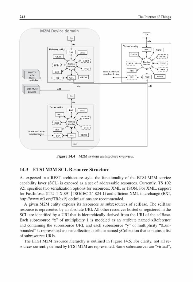
P1: TIX/XYZ P2: ABCJWST118-c14 JWST118-Hersent November 26, 2011 17:45 Printer Name: Yet to Come
242 The Internet of Things
Network entity
NA
Routingfunction
mIa
NAE
NGC
NCB
NTM
NREM
NCS
NRAR
mId
NSEC
NHDR
NTOE
NIP
to non-ETSI M2M compliant devices
Gateway entity
GA
Routingfunction
dIa
GAE
GGC
GCB
GTM
GREM
GCS
GRAR
mId
GSEC
GHDR
GIPe.g. ZigBee
Device entity
DA
Routingfunction
dIa
DAE
DGC
DCB
DTM
DREM
DCS
DRAR
mId
DSEC
DHDR
DIP
to non-ETSI M2M compliant devices
ETSI M2M devices
Non ETSI M2M
devices
M2M Device domain
mId
Figure 14.4 M2M system architecture overview.
14.3 ETSI M2M SCL Resource Structure
As expected in a REST architecture style, the functionality of the ETSI M2M servicecapability layer (SCL) is exposed as a set of addressable resources. Currently, TS 102921 specifies two serialization options for resources: XML or JSON. For XML, supportfor FastInfoset (ITU-T X.891 | ISO/IEC 24 824-1) and efficient XML interchange (EXI,http://www.w3.org/TR/exi/) optimizations are recommended.
A given M2M entity exposes its resources as subresources of sclBase. The sclBaseresource is represented by an absolute URI. All other resources hosted or registered in theSCL are identified by a URI that is hierarchically derived from the URI of the sclBase.Each subresource “x” of multiplicity 1 is modeled as an attribute named xReferenceand containing the subresource URI, and each subresource “y” of multiplicity “0..un-bounded” is represented as one collection attribute named yCollection that contains a listof subresource URIs.
The ETSI M2M resource hierarchy is outlined in Figure 14.5. For clarity, not all re-sources currently defined by ETSI M2M are represented. Some subresources are “virtual”,

P1: TIX/XYZ P2: ABCJWST118-c14 JWST118-Hersent November 26, 2011 17:45 Printer Name: Yet to Come
The ETSI M2M Architecture 243
Sclbase Attributes including references to sub-
resources
Sub-resource attributes
accessRightID ID of the access rights resource applicable to this SCL
creationTime Creation time attribute
lastModifiedTime Last modification time attribute
scop Points of Contact attribute
searchStrings Tokens used as keys for searching resources and contents
sclsReference/ Reference to SCLs collection subresource
accessRightId Access right id of the parent resource
creationTime Creation time
lastModifiedTime Last modification time
ecnerefeRjbOtmgm Reference to Management object resources
noitcelloClcs Reference to registered SCL resources
ecnerefeRsnoitpircsbus Reference to Subscription resources, see
Figure 12
applicationsReference Reference to Applications collection subresource
accessRightId Access right id of the parent resource
creationTime Creation time
lastModifiedTime Last modification time
noitcelloCnoitacilppa Reference to application resources, see
Figure 7
ecnerefeRsjbOtmgm Reference to management objects collection resources
ecnerefeRsnoitpircsbus Reference to Subscriptions collection resource
containersReference Reference to Containers collection subresource
accessRightId Access right id of the parent resource
creationTime Creation time
lastModifiedTime Last modification time
noitcelloCreniatnoc References to Container resources, see
Figure 10
noitcelloCnoitacol References to Location resources
ecnerefeRsnoitpircsbus Reference to Subscription collection resource
groupsReference Reference to Groups collection subresource
accessRightId Access right id of the parent resource
creationTime Creation time
lastModifiedTime Last modification time
noitcelloCpuorg References to group resources, see
Figure 11
ecnerefeRsnoitpircsbus Reference to Subscription collection resource
accessRightsReference Reference to AccessRights collection subresource
accessRightId Access right id of the parent resource
creationTime Creation time
lastModifiedTime Last modification time
noitcelloCthgiRssecca Reference to access right resources, see
Figure 14.5 ETSI M2M resource hierarchy overview.

P1: TIX/XYZ P2: ABCJWST118-c14 JWST118-Hersent November 26, 2011 17:45 Printer Name: Yet to Come
244 The Internet of Things
Figure 9
ecnerefeRsnoitpircsbus Reference to Subscription collection resource
subscriptionsReference Reference to Subscriptions collection subresource
noitcelloCnoitpircsbus Reference to access right resources, see
Figure 12
discoveryReference Reference to Discovery resource (virtual)
sIRUderevocsid List of resource URIs matching searchPrefix and filterCriteria
eziShctam number of resources that matched the filterCriteria
edoCsutats
detacnurT If URI list had to be truncated
Figure 14.5 (Continued)
that is, they serve to implement a specific function and typically can only be read and donot have an e-tag.
More detailed views can be found in Figure 14.6 for SCL resources, in Figure 14.7 forapplication resources, in Figure 14.10 for container resources, in Figure 14.9 for accessright resources, in Figure 14.11 for group resources, in Figure 14.12 for subscriptionresources, in Figure 14.13 for notification channels resources.
Applications register to a SCL simply by creating a new application resource under theapplications collection subresource. Remote SCLs register to a local SCL by creating anew SCL resource under the SCLs collection subresource.
Basic REST primitives define how to create, read, update or delete a resource inits entirety, but there are many cases where an application wants to interact with onlya part of the resource. TS102921 provides a number of conventions enabling partialresource read, write or subscription. For instance, single attributes or elements can beaddressed. For resources formatted as XML content, ETSI M2M supports the XCAP(XML configuration access protocol, RFC 4825) approach, which allows arbitrary xpathexpressions to manipulate parts of the XML representation of a resource.
14.3.1 SCL Resources
The sclCollection attribute of the SCLs collection subresource contains references to oneor more SCL resources. The structure of an SCL resource representation is outlined inFigure 14.6. represents the specific SCL resource name.
14.3.2 Application Resources
Application resources represent applications (DA, GA or NA). Applications register underone or more SCLs. They interact with the rest of the system via mIa (NA) or dIa (DA, GA)

P1: TIX/XYZ P2: ABCJWST118-c14 JWST118-Hersent November 26, 2011 17:45 Printer Name: Yet to Come
The ETSI M2M Architecture 245
<scl> Attributes including
references to sub-resources
Sub-resource attributes
accessRightID ID of the access rights resource applicable to this SCL
creationTime Creation time attribute
expirationTime Expiration time attribute
id Id attribute
lastModifiedTime last modification time attribute
onlineStatus ONLINE | OFFLINE | NOT_REACHABLE
pocs Points of Contact (network URI) of this SCL
searchStrings Tokens used as keys for searching resources and contents
Schedule Schedule that tells when an SCL is available
serverCapability If TRUE the registered SCL can handle incoming requests.
discoveryReference Reference to Discovery resource (virtual resource)
discoveredURIs List of resource URIs matching searchPrefix and filterCriteria
matchSize number of resources that matched the filterCriteria
statusCode
Truncated If URI list had to be truncated
notificationChannelReference Reference to Notification channel resources
creationTime Creation time of the resource
lastModifiedTime Last modification time
notificationChannelCollection List of notification channel resources, see
Figure 13
mngtObjsReference Reference to Management object collection subresource
… (TBD at the time of writing)
applicationsReference Reference to Application collection subresource
(see Figure 5)
(see Figure 5)
(see Figure 5)
(see Figure 5)
(see Figure 5)
containersReference Reference to Containers collection subresource
groupsReference Reference to Groups collection subresource
accessRightsReference Reference to AccessRights collection subresource
subscriptionsReference Reference to Subscriptions collection subresource
Figure 14.6 SCL resource representation.
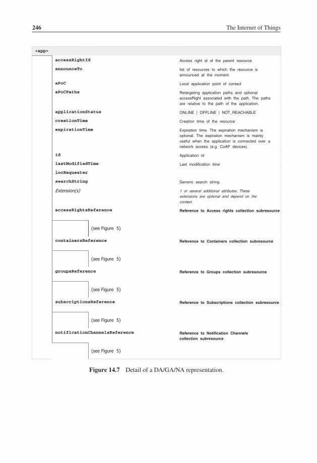
P1: TIX/XYZ P2: ABCJWST118-c14 JWST118-Hersent November 26, 2011 17:45 Printer Name: Yet to Come
246 The Internet of Things
<app>
accessRightId Access right id of the parent resource
announceTo list of resources to which the resource is announced at the moment.
aPoC Local application point of contact
aPoCPaths Retargeting application paths and optional accessRight associated with the path. The paths are relative to the path of the application.
applicationStatus ONLINE | OFFLINE | NOT_REACHABLE
creationTime Creation time of the resource
expirationTime Expiration time. The expiration mechanism is optional. The expiration mechanism is mainly useful when the application is connected over a network access (e.g. CoAP devices).
id Application id
lastModifiedTime Last modification time
locRequester
searchString Generic search string
Extension(s) 1 or several additional attributes. These extensions are optional and depend on the context.
accessRightsReference Reference to Access rights collection subresource
(see Figure 5)
(see Figure 5)
(see Figure 5)
(see Figure 5)
(see Figure 5)
containersReference Reference to Containers collection subresource
groupsReference Reference to Groups collection subresource
subscriptionsReference Reference to Subscriptions collection subresource
notificationChannelsReference Reference to Notification Channels collection subresource
Figure 14.7 Detail of a DA/GA/NA representation.

P1: TIX/XYZ P2: ABCJWST118-c14 JWST118-Hersent November 26, 2011 17:45 Printer Name: Yet to Come
The ETSI M2M Architecture 247
GET /m2m/applications/firstApp HTTP/1.1Host: m2m.example.com
HTTP/1.1 200 OKContent-Type: application/xml
<?xml version="1.0" encoding="UTF-8"?><application xmlns="http://uri.etsi.org/m2m">
<creationTime>2001-12-31T12:00:00.000</creationTime><searchStrings>
<searchString>tag1</searchString><searchString>tag2</searchString>
</searchStrings><containersReference>
http://m2m.operator.org/m2m/applications/firstApp/containers
</containersReference></application>
Figure 14.8 Example application resource application/xml serialization.
interfaces. Basic interactions may involve reading or writing any resource accessible by theSCL (typically reading or writing container subresources), provided that the applicationhas the relevant access rights to the resource (see Figure 14.9). This notion of genericaccess right is one of the key features of ETSI M2M, enabling secure sharing of the M2Mnetwork, gateways and devices by multiple applications.
Figure 14.8 shows an example serialization of an application resource, using applica-tion/xml.
<Access right>
announceTo list of resources to which the resource is announced at the moment
creationTime Creation time of the resource
expirationTime
lastModifiedTime Last modification time
searchStrings Tokens used as keys for searching resources and contents
permissions Permissions
selfPermissions Permissions on this resource
subcriptionsReference Reference to Subscriptions collection subresource
(see Figure 5)
Figure 14.9 Access right resource representation.

P1: TIX/XYZ P2: ABCJWST118-c14 JWST118-Hersent November 26, 2011 17:45 Printer Name: Yet to Come
248 The Internet of Things
This type of interaction based on reading or writing resources is adapted to manysituations, but not to all. For instance, an application may have a transient variable thatit wishes to expose to other applications (for instance a timer), but it would clearlybe inefficient to report the value of that transient variable to a network buffer. Otherapplications may offer access to a very large dataset, and the probability of externalapplications requesting access to some items in the dataset is very low, therefore publishingthe whole dataset would be a very inefficient model.
The notion of application point of contact (aPoC) provides a more dynamic interactionmodel with the application: retargeting. This feature requires that the application registeran application point of contact (see “aPoC” attribute in the resource tree). When anapplication does not provide an application point of contact, the SCL retargeting behavioris not available. In addition, the application may publish a set of application point ofcontact paths (“aPoCPaths” attribute), in order to restrict the SCL retargeting behaviorto only resources addressed by specific subpaths. In the absence of this parameter, theapplication accepts that any resource request may be retargeted if it has published anapplication point of contact. Each application point of contact path is a tuple containing:
� A path relative to the URI of the application path resource;� An optional access right identifier., which applies to all subresources subordinate URIs
of under this path. In the absence of such access right identifier, the access rights of theapplication registration resource apply.
The REST requests of an external application trying to interact with a subresourceidentified by a URI matching any of the application point of contact paths prefixes isretargeted by the SCL to the aPoC of the application. This enables the application torespond to the request directly without a need for an intermediary buffer.
14.3.3 Access Right Resources
The access right resource (Figure 14.9) is used to configure the permitted actions for agiven resource according to the action issuer.
The permissions attribute contains a list of “permission” elements. Each permissionelement is a triplet that associates:
– a permission id;– permission flags (READ, WRITE, DELETE, CREATE and DISCOVER);– permission holders (all, or specific permission holder URIs and specific domains iden-
tified by a path prefix).
14.3.4 Container Resources
Container resources provide a generic buffering capability which facilitates the exchangeof data between applications, particularly for applications residing on sleeping devices.

P1: TIX/XYZ P2: ABCJWST118-c14 JWST118-Hersent November 26, 2011 17:45 Printer Name: Yet to Come
The ETSI M2M Architecture 249
<container>
accessRightId Access right id of the parent resource
announceTo list of resources to which the resource is announced at the moment.
containerType
creationTime Creation time of the resource
expirationTime
di Id of the Container resource
lastModifiedTime Last modification time
searchStrings Tokens used as keys for searching resources and contents
maxByteSize Max byte size of instances
maxNrOfInstances Max number of instances
maxInstanceAge Max instance age. Define the max age of each content instance. The age is initialized when the content instance is created. The age is re-initialized each time that the content instance is updated.
Extension(s) 1 or several additional attributes. These extensions are optional and depend of the context.
contentInstancesReference Reference to Content instances collection subresource
creationTime Creation time of the resource
currentNrOfInstances Current number of instances in the resource
currentByteSize Current size in bytes of data stored in a container resource
lastModifiedtime Last modification time
latest Reference to the latest instance
oldest Reference to the oldest instance
contentInstanceCollection references to contentInstance subresources
characterEncoding
Content Content (opaque to ETSI M2M layer) represented as MIME part
contentSize Size in bytes of the content instance
contentType MIME Content type of the content instance
creationTime Creation time of the resource
delayTolerance The time before the addition/change of the containing <instance> resource shall be notified to any subscribers
href
id
lastModifiedTime Last modification time
Extension(s) 1 or several additional attributes. These extensions are optional and depend of the context.
subscriptionsReference Reference to Subscriptions collection subresource
(see Figure 5)
subcriptionsReference Reference to Subscriptions collection subresource
(see Figure 5)
Figure 14.10 Detail of a container representation.

P1: TIX/XYZ P2: ABCJWST118-c14 JWST118-Hersent November 26, 2011 17:45 Printer Name: Yet to Come
250 The Internet of Things
ETSI M2M has structured this generic container into multiple time-indexed contentIn-stances. The contentInstance metadata identifies the MIME type of the contentInstancecontent, which is encoded as MIME part. The preferred MIME encoding is MTOM/XOP(application/xop+xml) as specified in http://www.w3.org/TR/xop10/ in order to avoid theoverhead of base64 encoding.
This choice of a single index (time) for content instances is somewhat limitative com-pared to advanced metering protocols that handle multi-index storage structures (andprovide read queries based on multiple indexes). We expect this limitation to be removedin future versions of ETSI M2M, in the interim searchstring tags may be used for multi-category indexing of contentInstances.
14.3.5 Group Resources
Group resources (Figure 14.11) make it possible to address a group of resources in asingle operation, by addressing the group membersContentReference virtual resource.Currently, the types of resources that can be grouped are application, container, accessright, and SCL.
<group>
accessRightId
announceTo list of resources to which the resource is announced at the moment.
creationTime Creation time of the resource
currentNrOfMembers Current number of members in a group
expirationTime
lastModifiedTime
maxNrOfMembers
Members URI list of group members
memberType APPLICATION | CONTAINER | ACCESS_RIGHT |
SERVICE_CAPABILITY_LAYER
searchStrings Tokens used as keys for searching resources and contents
membersContentReference Virtual resource that corresponds to requests that would be sent to resource of the corresponding memberType
membersContentResponses Collection of MemberContentResponse
subscriptionsReference
(see Figure 5)
Figure 14.11 Group resource representation.
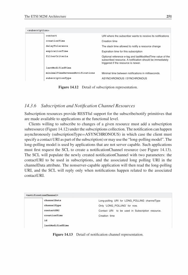
P1: TIX/XYZ P2: ABCJWST118-c14 JWST118-Hersent November 26, 2011 17:45 Printer Name: Yet to Come
The ETSI M2M Architecture 251
<subscription>
URI where the subscriber wants to receive its notifications
creationTime Creation time
delayTolerance The slack time allowed to notify a resource change
expirationTime Expiration time for this subscription
filterCriteria Optional reference e-tag and lastModifiedTime value of the subscribed resource. A notification should be immediately triggered if the resource is newer.
lastModifiedTime
minimalTimeBetweenNotifications Minimal time between notifications in milliseconds.
subscriptionType ASYNCHRONOUS | SYNCHRONOUS
contact
Figure 14.12 Detail of subscription representation.
14.3.6 Subscription and Notification Channel Resources
Subscription resources provide RESTful support for the subscribe/notify primitives thatare made available to applications at the functional level.
Clients willing to subscribe to changes of a given resource must add a subscriptionsubresource (Figure 14.12) under the subscriptions collection. The notification can happenasynchronously (subscriptionType=ASYNCHRONOUS) in which case the client mustspecify a contact URI as part of the subscription) or may use the “long-polling model”. Thelong-polling model is used by applications that are not server capable. Such applicationsmust first request the SCL to create a notificationChannel resource (see Figure 14.13).The SCL will populate the newly created notificationChannel with two parameters: thecontactURI to be used in subscriptions, and the associated long polling URI in thechannelData attribute. The nonserver-capable application will then read the long-pollingURI, and the SCL will reply only when notifications happen related to the associatedcontactURI.
<notificationChannel>
channelData Long-polling URI for LONG_POLLING channelType
channelType Only ‘LONG_POLLING’ for now.
contactURI Contact URI to be used in Subscription resource.
creationTime Creation time
id
lastModifiedTime
Figure 14.13 Detail of notification channel representation.

P1: TIX/XYZ P2: ABCJWST118-c14 JWST118-Hersent November 26, 2011 17:45 Printer Name: Yet to Come
252 The Internet of Things
The notification content includes the subscription URI, as well as the latest representa-tion of the subscribed-to resource.
14.4 ETSI M2M Interactions Overview
An application may interact with resources on the local SCL provided that the accessRightsof that resource allow the type of action for the issuer application. An application mayalso interact with resources located on other SCLs, in which case the local SCL forwardsthe request to the target SCL, and access rights are checked by the target SCL.
ETSI M2M provides several options for the handling of request responses:
– Synchronous response: the expected response content is delivered in the response ofthe original request, which is blocked until a response becomes available or a timeouterror occurs.
– Semiasynchronous response: requests include correlation data. If the expected re-sponse content cannot be delivered immediately, the target SCL sends an acknowledgeindication and an indication of the minimum time to wait before sending a new request.The issuer SCL is expected to reissue the request with the same correlation data, untilit obtains the expected response content in the target SCL response.
– Asynchronous: the local SCL needs to be server capable, and provides a contact_serverURI for responses, as well as correlation data in each request, so that responses receivedover the server URI can be associated to the corresponding requests.
14.5 Security in the ETSI M2M Framework
14.5.1 Key Management
ETSI M2M uses a key hierarchy:
� The root key KR is the long-term secure key and is stored in the network and the device.It is used to derive the service keys. Depending on the underlying network technologyKR can be stored at the network level in a secure element (e.g., SIM card) or at theservice capability layer. KR is typically preinstalled and shared between the networkand the gateway.
� The service key KS is derived from the root key during the authentication and authoriza-tion of the M2M service layer. KS is derived during the gateway-registration procedureto the network, and associated to the session (it may expire and be renewed during thesession). The service key is not available to applications.

P1: TIX/XYZ P2: ABCJWST118-c14 JWST118-Hersent November 26, 2011 17:45 Printer Name: Yet to Come
The ETSI M2M Architecture 253
User Equipment(UE)
Bootstrapping Server Func�on(BSF)
Ub(3GPP TS 24.109)
Network Applica�on Func�on(NAF)
Home Subscriber Server(HSS)
Zh(3GPP TS 29.109)
Ua(3GPP TS 24.109)
Upa(3GPP TS 24.109)
Creates a security associa�on (bootstrapping transac�on iden�fier B-TID and key material Ks) between UE and BSF. Based on RFC 3310: "HTTP Digest Authen�ca�on Using Authen�ca�on and Key Agreement (AKA)".
Zn (3GPP TS 29.109)
Applica�on request (B-TID, msg)
Authen�ca�on request (B-TID, NAF_ID)
Auth.resp. (Ks_NAF/Ks_NAF_ext, security profiles, key life�me)
Provides a push mechanism to create a bootstrapped security associa�on between the UE and NAF for secure communica�on of pushed messages
Uses the bootstrapped security associa�on between UE and NAF for secure communica�on
Retrieve auth. vectors from HSS, use one to challenge UE
= ETSI M2M KR
Figure 14.14 Generic authentication architecture (GAA, 3GPP TS 33.220).
� The optional application key KA. There is one application key per application that wishesto manage its own security context. KA will be used for authentication and authorizationof M2M applications at the M2M device or gateway. At the time of writing, the exactuse of KA was not specified.
TR102921 describes the several security bootstrapping mechanisms. Some options lever-age on existing security bootstrapping frameworks at the access-network level, forexample, the 3GPP generic bootstrapping architecture (GBA over the 3GPP Ub inter-face defined in 3GPP TS 24.109, see Figure 14.14) that uses SIM or USIM card securitymaterial to derive a shared key between the M2M gateway (user equipment) and theMSBF (acting as 3GPP NAF, via the NSCL).
Other options are completely independent of the underlying transport network, forexample, using EAP over PANA transport, with the M2M gateway acting as EAP peerand PANA client, the NSCL as EAP authenticator and PAN authentication agent, and theMSBF acting as EAP authentication server (Figure 14.15).

P1: TIX/XYZ P2: ABCJWST118-c14 JWST118-Hersent November 26, 2011 17:45 Printer Name: Yet to Come
254 The Internet of Things
M2M GW NSCL
PANA
MSBF
AVPs: M2M GW Device IDPANA Client Ini�a�on
PANA Authen�ca�on request
Diameter or other
AVPs: M2M NSCL ID, M2M MSBF ID
PANA Authen�ca�on Answer
PANA Authen�ca�on request AVPs: PANA EAP informa�on
AVPs: PANA EAP informa�onPANA Authen�ca�on Answer
PANA Authen�ca�on request bit: setComple�onAVPs: M2M-bootstrap-result : success(opt.) : M2M-DM-Server-Id(opt.) : M2M-Assigned-Device-Gateway-Id
EAP infoTunelledPANA Authen�ca�on Answer
KR = Hash(EAP Extended Master Session Key, “ETSI M2M Device-Network Root Key” | M2M-Assigned-Device-Gateway-Id | M2M-Domain-Id)
Figure 14.15 PANA/EAP ETSI M2M security bootstrapping.
14.5.2 Access Lists
The ETSI M2M framework is designed to enable usage of a shared M2M infrastructure(network, gateways, sensors and devices) by multiple applications.
The security aspects are very important in this context:
– A given end-user (e.g., a residential subscriber) owning several sensors under controlof his local M2M gateway will of course not want to publish sensor data, or provideaccess to actuators, to anyone. ETSI M2M provides an access-control list (ACL) formost resources published by the M2M gateway SCL. In the example of Figure 14.7,the user, by configuring properly the ETSI M2M gateway SCL ACLs can decide whichnetwork application can perform which REST action (e.g., read or write) on whichdevice application, or even on which container of which device application.
Of course, the average end user will never deal with the details of ETSI M2M. Instead,a user-friendly interface will be provided by the M2M service provider. In the exampleof Figure 14.16, the M2M service provider presents each “network application” (ordevice application, or group of related NA and DA applications) as an icon, using thenow-familiar application store design. In Figure 14.17, the user is configuring a sensor,and is asked which applications can access this sensor information: behind the scenes,

P1: TIX/XYZ P2: ABCJWST118-c14 JWST118-Hersent November 26, 2011 17:45 Printer Name: Yet to Come
The ETSI M2M Architecture 255
Applica�ons view
/Home
App name
!
App name App name App name
App name App name App name App name
App name App name App name App name
App name App name App name App name
Dashboard Store Se�ngs
Figure 14.16 A possible user interface for ETSI M2M service configuration.
the middleware will configure the proper ACLs in the representation of that sensor onthe gateway SCL.
14.6 Interworking with Machine Area Networks
ETSI M2M provides a very interesting model to interact with multiple machine areanetworks in a homogeneous way, enabling network or gateway applications to interact withthese networks with minimal customization requirements. For most applications, only thespecific sensor/actuator URIs and parameter names need to be configured or discovered:the actual underlying protocol details of the machine area networks are abstracted by theETSI M2M framework.
ETSI TR 102 966 “Interworking with M2M Area Networks” explores the specificmappings recommended for interworking with other M2M technologies, such as ZigBee.

P1: TIX/XYZ P2: ABCJWST118-c14 JWST118-Hersent November 26, 2011 17:45 Printer Name: Yet to Come
256 The Internet of Things
Device Edit
Cancel Ok
Vendor name
Product name
Personal name [_________________________]
Place Bedroom Configure
Optional tech element 1 [_____________________]
Optional tech element 2 [_____________________]
Optional tech element 3 [_____________________]
Used by applications
Application name 1 Full access Read Only No linkApplication name 2 Full access Read Only No linkApplication name 3 Full access Read Only No link
Delete device
Device List
Figure 14.17 Security configuration screen for a sensor.
At the time of writing this section, the document was still in early draft stage, however,the author was an active participant in the elaboration of this technical report, and believesthat the approach outlined below will be very close to the final recommendation.
14.6.1 Mapping M2M Networks to ETSI M2M Resources
There are many potential ways of mapping M2M networks to ETSI M2M standard re-sources. One possibility is to attempt to recreate the hierarchy of native M2M networkswithin the hierarchy of ETSI M2M resources (e.g., SCLs for top-level networks, appli-cations for nodes, etc. . . .). However, obviously, it is impossible to replicate the exact

P1: TIX/XYZ P2: ABCJWST118-c14 JWST118-Hersent November 26, 2011 17:45 Printer Name: Yet to Come
The ETSI M2M Architecture 257
resource hierarchy of any network, which can get quite deep. In the case of ZigBee forinstance (refer to Chapter 7), each controller may access a collection of networks, eachwith a number of devices hosting a number of applications. Each application publishesan interface composed of a number of clusters, and each cluster is composed of multipleattributes and primitives!
The preferred option is to represent external machine area networks as a collection ofapplications (GA or DA). Any resource hierarchy present in the native M2M networkis recreated by means of pointer attributes: the ETSI M2M application representing theparent object will expose special attributes pointing to child objects.
Recognizing that most automation protocols use a similar datamodel structure, TR102 966 introduces specific ‘tags’ (special searchString values) to identify the type of‘object’ modeled by the application in a protocol independent way:
– ETSI.ObjectType tags (for instance ETSI.ObjectType/ETSI.AN_NWK) are usedto discriminate between applications representing Interworking Proxy objects(ETSI.ObjectType/ETSI.IP), Network objects (ETSI.ObjectType/ETSI.AN_NWK),Device objects (ETSI.ObjectType/ETSI.AN_DEV), Application objects (ETSI.ObjectType/ETSI.AN_APP), and Point objects (ETSI.ObjectType/ETSI.AN_POINT).The various object types will be illustrated in the example of ZigBee (see Section 14.6.2).
– ETSI.ObjectSemantic tag (for instance ETSI.ObjectSemantic /OASIS.OBIX_1_1) isused to discover the semantic conventions supported by the object. The syntax ofan object representation is usually indicated by its Content-Type, for instance appli-cation/xml. However, multiple semantic conventions may leverage the same syntac-tic rules. In the use case of interworking with control and sensor networks, exam-ples of such semantic conventions leveraging application/xml syntax are OASIS oBix(ETSI.ObjectSemantic/OASIS.OBIX_1_1), ZigBee Gateway Device REST binding, orASHRAE BACnet annex am (ETSI.ObjectSemantic/ASHRAE.CSML_1_0).
ETSI M2M implements a REST design model that allows multiple representationsof the objects manipulated through the ETSI M2M SCL.
– ETSI.ApplicationProfile tags are reserved for future use. The intent is to be able tofacilitate search of specific devices for example, “lamps”. Nomenclatures have beencreated by ZigBee, KNX and LonWorks, and one is being worked on by BACnet. Futurework would lead to a harmonized nomenclature that would use this tag category
14.6.2 Interworking with ZigBee 1.0
Interworking with ZigBee 1.0 networks leverages the ZigBee Alliance “Gateway specifi-cation for network devices”, version 1.0 (refer to Chapter 7 for details). This specificationexposes how a ZigBee gateway devices (ZGD) exposes the ZigBee network resources toIP host applications (IPHA), over several network bindings.
An ETSI M2M application (local gateway application or device application in thecase of a separate ZigBee interworking device) models the ZGD and acts as an

P1: TIX/XYZ P2: ABCJWST118-c14 JWST118-Hersent November 26, 2011 17:45 Printer Name: Yet to Come
258 The Internet of Things
version /zgd0/version
/applica�ons/zgd0
1
energy
ib /zgd0/ib
<A�ribute> /zgd0/ib/<A�ribute>
reset
startup
networks
<address> /zgd0/networks/<address>
Networks a�ached to the ZGD : network forma�on, Start router, Join procedure, reset, discover networks
Perform energy scan
ETSI M2M applica�on ac�ng as ZigBee interworking func�on
1
ZGD Gateway informa�on base
0..*
A�ribute 0x00 : ZigBee radio statuse.g. 0x07 : has formed a network
A specific network a�ached to the ZGD/zgd0/networks
/zgd0/energy
/zgd0/reset Startup parameters
/zgd0/startup
/applica�ons/zigbeeNet_0012213344556677
Interworking with a specific ZigBee network is handled by a dedicated M2M applica�on, located at <NWKRootURI>
Figure 14.18 ZGD REST representation as a standard ETSI M2M application.
interworking proxy. It has a searchString attribute containing technology-independenttag “ETSI.ObjectType/ETSI.IP” so that applications may discover this application, whichhas interworking proxy capability. This application contains one <container> subre-source that has a searchString containing tag “ETSI.ObjectType/ETSI.IP”, and a tag ofcategory ETSI.ObjectSemantic (oBix for our examples below). The latest contentInstanceof this container lists the networks supported by this interworking proxy (in a protocol-independent way) as well as proxy capability information. Each network element pointsto the ETSI M2M application that represents it. This container instance may also in-clude links to the ZGD representation defined by the ZigBee alliance (Figure 14.18). Anexample interworking proxy representation is shown in Figure 14.19.
Each ZigBee network is represented by a specific ETSI M2M application located atthe URI specified in the ‘networks’ list. Applications representing a network have asearchString containing tag: ETSI.ObjectType/ETSI.AN_NWK, and one container withthe same tag. The latest contentInstance of this container contains the representation ofthe network. Figure 14.20 illustrates how a client application can read this resource.
The representation of the network contains the network identifier and the list of nodes(in a protocol independent way), as well as technology-specific information related to thenetwork. Each ZigBee node is represented by a specific ETSI M2M application located atthe URI specified in the ‘nodes’ list. Applications representing a node have a searchStringcontaining tag: ETSI.ObjectType/ETSI.AN_DEV, and one container with the same tag.

P1: TIX/XYZ P2: ABCJWST118-c14 JWST118-Hersent November 26, 2011 17:45 Printer Name: Yet to Come
The ETSI M2M Architecture 259
>>> HTTP GET/gsc/applications/zgd0/containers/descriptor/contentInstances/last/content
<<< 200 OK<obj>
<str name="interworkingProxyID" val="Text for correla-tion purpose"/>
<list name="supportedTechnologies">
<obj>
<enum name="anStandard" val="ZigBee_1_0"/>
<enum name="anProfile" val="ZigBee_HA"/>
<enum name="anPhysical"val="IEEE_802_15_4_2003_2_4GHz"/>
</obj>
</list>
<list name="networks"/>
<ref href="/gsc/applications/zbnw0/">
</list>
</obj>
Figure 14.19 Retrieving the M2M application resource modeling the ZGD via HTTP GET.
>>> HTTP GET/gsc/applications/zbnw0/containers/descriptor/contentInstances/last/content
<<< 200 OK<obj>
<str name="networkID" val="Text for correlationpurpose"/>
<str name="extendedPanID" val"0x685B3C34"/>
<list name="nodes"><ref href="/gsc/applications/zbnode0/"/>
</list></obj>
Figure 14.20 Retrieving the M2M application resource modeling the ZigBee network via HTTPGET.

P1: TIX/XYZ P2: ABCJWST118-c14 JWST118-Hersent November 26, 2011 17:45 Printer Name: Yet to Come
260 The Internet of Things
>>> HTTP GET/gsc/applications/zbnode0/containers/descriptor/contentInstances/last/content
<<< 200 OK<obj>
<str name="nodeID" val="Text for correlation purpose"/><str name="ieeeAddress" val="0x685B3C88"/><enum name="type" val="endDevice"/>
<list name="applications"><ref href="/gsc/applications/zbapp0/"/>
</list></obj>
Figure 14.21 Retrieving the M2M resource for a node via HTTP GET.
The latest contentInstance of this container contains the representation of the node. Figure14.21 illustrates how a client application can read this resource.
Our example network has a single node. Each node may host multiple appli-cations, for instance multiple switches or lamp controllers. ZigBee identifies eachapplication as an ‘endpoint’. Each ZigBee endpoint is represented by a specific ETSIM2M application located at the URI specified in the node ‘applications’ list. ETSIM2M Applications representing a node application1 have a searchString containing tag:ETSI.ObjectType/ETSI.AN_APP, and one container with the same tag. The latest con-tentInstance of this container contains the representation of the node application, in thiscase a ZigBee endpoint. Figure 14.22 gives an example representation of a node applica-tion resource.
Each node application may implement multiple interfaces. ZigBee identifies eachinterface as a ‘cluster’. Interfaces may be represented as separate applications (theelement is a reference to the M2M application), but in the example of Figure 14.22 thecontentInstance data includes the actual interface content. Each interface contains proto-col dependent primitives (e.g. ‘toggle’) as well as a number of attributes (e.g. ‘OnOff’).TR 102 966 offers an abstraction for attributes representing measurements: the Pointthat may include protocol-independent specification of units, range, etc. (It is not used inthe example).
When the ZigBee interworking application starts, it audits all networks and replicatesa view of the ZigBee network topology in the GSC (Figure 14.23). This view includesall ZigBee nodes and all ZigBee applications (endpoints). When a new ZigBee node is
1 Node applications are applications running in sensors, not to be confused with the M2M applicationresources that model them.

P1: TIX/XYZ P2: ABCJWST118-c14 JWST118-Hersent November 26, 2011 17:45 Printer Name: Yet to Come
The ETSI M2M Architecture 261
...<int name="endpoint" val="1"/><int name="applicationProfileID" val="0x0104"/><int name="applicationDeviceID" val="0x0100"/>
<list name="Interfaces"><obj>
<str name="clusterID" val="0x0006"/><enum name="clusterType" val="input"/>
<list name="attributes"><ref name="0x0000"
href="/<sclBase>/applications/<networkX_nodeY_applicationZ>/containers/0x0006_OnOff"/>
</list>
<list name="operations"><op name="0x00"
href="/<sclBase>/applications/<interworking_proxy_unit>/0x0006_off"/>
<op name="0x01"href="/<sclBase>/applications/<interworking_proxy_unit>/0x0006_on"/>
<op name="0x02"href="/<sclBase>/applications/<interworking_proxy_unit>/0x0006_toggle"/>
</list></obj>
</list>...
Figure 14.22 Extract of the ZigBee endpoint representation.
added in the network, the ZigBee HAN representation is immediately updated to reflectthis change in the GSC.
At this stage, other gateway or network applications can discover the elements of theZigBee networks by retrieving the resources maintained in the GSC by the driver. Theycan also subscribe to the representation changes, if the driver supports it (and creates theappropriate subscriptions collections in the ZigBee network representation).

P1: TIX/XYZ P2: ABCJWST118-c14 JWST118-Hersent November 26, 2011 17:45 Printer Name: Yet to Come
262 The Internet of Things
gsc
2. Create() / Update()
driver
2. Create() / Update()
4. Create() / Update()
6. Create() / Update()
4. Create() / Update()
6. Create() / Update()
1.Audit network
coordinator(znp)
1.Audit network
5.Audit applications
device
3.Audit nodes
5.Audit applications
3.Audit nodes
Figure 14.23 ZigBee driver explores the ZigBee network and creates the SCL representations.
14.6.3 Interworking with C.12∗
In order to prove the versatility of ETSI M2M standards and their ability to provide a com-mon framework for interfaces to existing standards, we explore in this section the interfaceto C.12 metering standards. As mentioned in Chapter 10, the communication protocol forthe transport of C12.19 tables requires only basic read and write services. Such standard-ization of communication patterns using few verbs is typical of REST design principles.
As ETSI M2M decided to use a RESTful approach for specifying its interface betweenM2M applications and the service capability layer, we attempt to use this interface to in-teract with C12.19 tables accessible over a C12 network. At first sight, a REST-styleinterface can be achieved by mapping each C12.19 table to a corresponding RESTresource. The basic read and write services can also easily be mapped on the classi-cal CRUD verbs (create, retrieve, update, delete).
In the DLMS/COSEM case (see Chapter 11), the data communication services acces-sible to the metering application are a little more complicated than read/write due to theexistence of the “action” service. An intermediate resource has to be used in order tocommunicate the name of the “action” and the associated parameters in a REST style.In the C12.19 data model it is easier since the possible “actions” are already included intwo specific tables (Tables #07 and #08). The “action” is called “procedure” and a requestfor executing a specific procedure corresponds to the invoke of the basic write service forTable #07.
Our purpose here is not to propose a specification of what would interface to nativeRESTful C12 meters, but instead we attempt to define an interworking function between
∗This section is contributed by Jean-Marc Ballot.
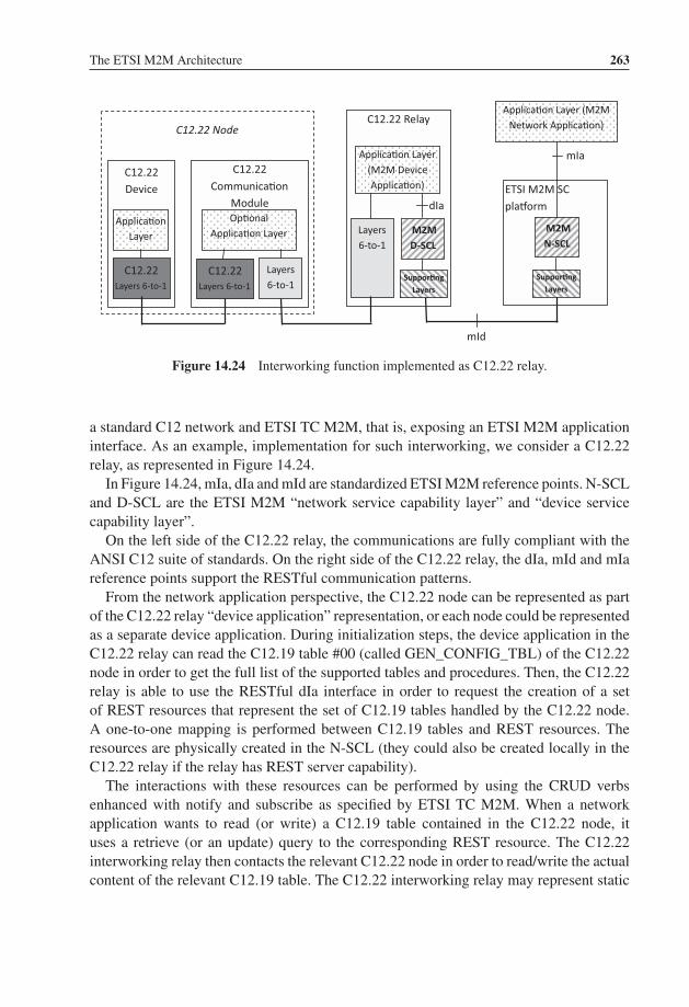
P1: TIX/XYZ P2: ABCJWST118-c14 JWST118-Hersent November 26, 2011 17:45 Printer Name: Yet to Come
The ETSI M2M Architecture 263
C12.22 Device
C12.22 Communica�on
Module
Applica�on Layer
C12.22 Layers 6-to-1
Op�onal Applica�on Layer
Layers 6-to-1
mId
C12.22 Layers 6-to-1
C12.22 Relay
Layers 6-to-1
Applica�on Layer (M2M Device Applica�on)
M2MD-SCL
ETSI M2M SC pla�orm
M2M N-SCL
Applica�on Layer (M2M Network Applica�on)
dIa
mIa
Suppor�ngLayers
Suppor�ngLayers
C12.22 Node
Figure 14.24 Interworking function implemented as C12.22 relay.
a standard C12 network and ETSI TC M2M, that is, exposing an ETSI M2M applicationinterface. As an example, implementation for such interworking, we consider a C12.22relay, as represented in Figure 14.24.
In Figure 14.24, mIa, dIa and mId are standardized ETSI M2M reference points. N-SCLand D-SCL are the ETSI M2M “network service capability layer” and “device servicecapability layer”.
On the left side of the C12.22 relay, the communications are fully compliant with theANSI C12 suite of standards. On the right side of the C12.22 relay, the dIa, mId and mIareference points support the RESTful communication patterns.
From the network application perspective, the C12.22 node can be represented as partof the C12.22 relay “device application” representation, or each node could be representedas a separate device application. During initialization steps, the device application in theC12.22 relay can read the C12.19 table #00 (called GEN_CONFIG_TBL) of the C12.22node in order to get the full list of the supported tables and procedures. Then, the C12.22relay is able to use the RESTful dIa interface in order to request the creation of a setof REST resources that represent the set of C12.19 tables handled by the C12.22 node.A one-to-one mapping is performed between C12.19 tables and REST resources. Theresources are physically created in the N-SCL (they could also be created locally in theC12.22 relay if the relay has REST server capability).
The interactions with these resources can be performed by using the CRUD verbsenhanced with notify and subscribe as specified by ETSI TC M2M. When a networkapplication wants to read (or write) a C12.19 table contained in the C12.22 node, ituses a retrieve (or an update) query to the corresponding REST resource. The C12.22interworking relay then contacts the relevant C12.22 node in order to read/write the actualcontent of the relevant C12.19 table. The C12.22 interworking relay may represent static
P1: TIX/XYZ P2: ABCJWST118-c14 JWST118-Hersent November 26, 2011 17:45 Printer Name: Yet to Come
264 The Internet of Things
C12 node parameters as container data. Read/writes to dynamic parameters will preferablyuse the ETSI M2M retargeting mechanism already described above:
� The REST resources that have to be directly requested from the real legacy C12.22node are not physically stored in the SCL, instead the SCL mirrored information willonly contain a pointer to these resources, and specify that retargeting is supported. Theretargeted queries can be sent to the application point of contact, which must be publishedby the device application (the interworking C12.22 relay) during the initialization phase.
� When a request is sent by a network application that targets a resource not stored inthe SCL, the SCL retargets the request to the device application by forwarding it to theapplication point of contact. The device application can then read (or write) the realcontent by communicating with the C12.22 node.
This redirection mechanism is not only useful in the case of interworking but also makeit possible to implement natively ETSI M2M compliant C12 meters. Such a C12 meterwould implement a RESTful dIa interface, and would be able to mirror static C12.19REST resources in the SCL. For C12.19 tables that are volatile or too frequently changing(e.g., time elapsed since a specific event, time remaining before a specific event, con-sumption metering counters), the redirection mechanism is used instead and the mirroredrepresentation would store only pointers.
14.6.4 Interworking with DLMS/COSEM
ETSI TC M2M decided to use a RESTful approach for the interface between M2Mapplications and the service capability layer. The interworking with DLMS/COSEMmeters is not trivial because DLMS/COSEM uses an object oriented approach that is notRESTful compliant.
DLMS/COSEM meters are “legacy devices” according to the ETSI M2M referencearchitecture document and interworking will be performed by an interworking proxy (NIPor GIP), located in a M2M gateway (GIP) or in the core network (NIP). At the time ofwriting, ETSI TC M2M had not yet fully specified the interworking proxy function. In thefollowing text, we are proposing a possible approach in line with the current specification,based on a network-based interworking proxy (NIP), and illustrated on Figure 14.25.
We are assuming that the network application interacting with the DLMS meter isETSI M2M compliant. The NIP could be implemented as a new interface on DLMS dataconcentrators. This would be an option to standardize the interactions between networkapplications and data concentrators (currently out of scope of DLMS/COSEM).
The network interworking proxy (NIP) is considered as a part of the ETSI M2Mplatform. It contains a COSEM client AP and a COSEM client AL. The communicationsbetween the client parts in the NIP and the server parts in the metering equipment use theDSML/COSEM specifications. Once the client AP has established an association withthe server AP in the meter, a set of the COSEM interface objects becomes accessible.

P1: TIX/XYZ P2: ABCJWST118-c14 JWST118-Hersent November 26, 2011 17:45 Printer Name: Yet to Come
The ETSI M2M Architecture 265
COSEMserver AP
COSEMserver AL
Suppor�nglayers
Meter
IEC interface
COSEMclient AP
COSEMclient AL
Suppor�ng layers
IEC interface
X
Network Interworking Proxy
M2MNSC
NA
mIa
mId
ETSI M2M SCL pla�orm
Figure 14.25 ETSI M2M – DLMS/COSEM interworking using a network interworking proxy(NIP).
The “X” part of the NIP in Figure 14.25 represents the new software added for ETSIM2M interworking.
From a RESTful point of view, each COSEM interface object can be represented asa resource: the NIP first reads each COSEM interface object by using the standardizedCOSEM GET service. Then, after reading the object, the corresponding resource iscreated in the SCL layer. Only static parameters should be stored in the SCL. Volatileparameters such as counter values should be listed in SCL resources only as indirections,that is, read requests from network applications will be retargeted by the SCL to theinterworking proxy.
The DLMS specifications also define an ACTION service enabling a client AP toremotely invoke one or more methods of COSEM interface objects. This interaction pat-tern can also leverage the ETSI M2M retargeting mechanisms: SCL representations ofCOSEM interface objects will list a subresource for each supported action. The NA mayinvoke an action by sending a POST request targeted to the corresponding subresource(and containing the action parameters). The write request will be retargeted to the inter-working proxy by the SCL, and the interworking proxy will convert the request to a nativeDLMS/COSEM action service invocation. Synchronous responses will be provided in the200 OK response.2
2 In the case of asynchronous responses, the NIP response may just be 201 created, and the asynchronousresponse may be sent later to a resource supplied a part of the invoke parameters.

P1: TIX/XYZ P2: ABCJWST118-c14 JWST118-Hersent November 26, 2011 17:45 Printer Name: Yet to Come
266 The Internet of Things
NANSC COSEM
Client ALMeter COSEM Client
AP+X NIP
1. EventNotif.req (COSEM_Object1, Attribute1, Value)
2. EventNotif.ind (COSEM_Object1, Attribute1, Value) 3. UPDATE(Resource1)
4. NOTIFY(Resource1)
Figure 14.26 DLMS event-notification interworking with ETSI M2M.
The meter may also send an EventNotification, this case represents the exception of theDLMS client–server model. This notification contains the value of a COSEM interfaceobject attribute. This interworking case is illustrated in Figure 14.26.
In step 1, the meter needs to inform the client AP of the value of one attribute (Attribute1)of one COSEM object (Object1). The meter uses the COSEM EventNotification servicein order to provide the client AP with the attribute value (step 2).
The NIP has to update Resource1 that corresponds to Object1 in the REST environment.As a single attribute of Object1 is modified, a partial update is performed.3 The networkapplication will be notified of this update if it subscribed to Resource1.
14.7 Conclusion on ETSI M2M
Just like networked information systems played a fundamental role in the transformationof almost every business, connected objects will fundamentally change the design of mostindustrial and automation processes (see for instance draft-ietf-6LoWPAN-usecases). TheInternet emerged as the information backbone interconnecting all information systems,and the Internet of Things is now emerging as the backbone interconnecting all objects.
A common view is to consider that the IoT will be just one giant peer to peer IPv6network (there are about 6 × 1027 IPv6 addresses per square meter on earth). But thereare several problems with this view:
3 However, if partial updates are not allowed, due to some internal policy in the REST server, the NIP willhave to retrieve Resource1, locally update its content with the new value of the Attribute1, then perform a fullupdate of Resource1.

P1: TIX/XYZ P2: ABCJWST118-c14 JWST118-Hersent November 26, 2011 17:45 Printer Name: Yet to Come
The ETSI M2M Architecture 267
– For most actual sensor networks using low-bitrate and lossy networks (LLNs), standardIPv6 is not usable: 6LoWPAN will be used instead. The usable addressing space, notablyfor destination addresses, is very limited and not optimized for any to any worldwidecommunication. 6LoWPAN is optimized for a local or regional sensor network.
– Basic security considerations force the introduction of application-level gateways be-tween private domains and the public side of the internetwork. Today, the much-toutedexhaustion of IPv4 addresses does not have the screaming halt effect one might ex-pect on the development of the Internet: this is because all corporations use privateaddresses internally, and their firewalls map on demand these private addresses to veryfew external public IP addresses using NAPT (network address and port translation) orapplication-level proxies, e.g., for HTTP). The same will probably go for the Internet ofThings, private 6LoWPAN clouds will be interconnected by application-level gateways.
ETSI M2M is currently the only candidate standard for such “inter-networks of things”application-level gateways. It provides a standard data model for machine area networks,a standard access control list format, and a global application-level addressing mechanismfor connected objects. This design ensures that any application on earth can access anysensor, but not using the sensor IPv6 address directly (it may be a private address),using instead the application level URI for the sensor that can be used to route theapplication requests to the proper object network access gateway, under control of itsACLs. Such gateways are also the ideal place for fieldbus protocol interworking, basedon the normalized REST representation of each fieldbus network.
We believe the ETSI M2M framework will become the necessary complement of 6LoW-PAN for service providers envisioning very large scale, multipurpose M2M infrastructuredeployments.

P1: TIX/XYZ P2: ABCJWST118-c15 JWST118-Hersent November 30, 2011 8:3 Printer Name: Yet to Come
Part FiveKey Applicationsof the Internetof Things

P1: TIX/XYZ P2: ABCJWST118-c15 JWST118-Hersent November 30, 2011 8:3 Printer Name: Yet to Come
15The Smart Grid
15.1 Introduction
The smart grid will be one of the most important applications of the Internet of Things.A major paradigm change is happening in electricity markets, driven by the convergence
of several factors:
– The challenges posed by the accelerated introduction of renewable-energy sources inthe overall electricity production, which brings an increasing degree of randomness tothe traditionally deterministic supply side.
– The ubiquitous penetration of the Internet in homes and businesses, and the increasedconfidence in next-generation smart distributed networks for mission-critical applica-tions (after years of experience of the successful migration of telephony networks toVoIP).
– The gradual opening of electricity markets, with new regulation opening productionfacilities and distribution networks to all actors, greater fluidity in electricity trademarkets, and fast maturing of the regulatory framework for active utility operators,such as those implementing demand response.
– The increasing volatility of electricity prices, resulting from the underlying volatility ofoil and natural gas, but also increasingly from the propagation of external shocks, suchas exceptional climatic events, through energy exchanges.
The current credo of electricity operators “demand is unpredictable, and our expertise isto adapt production to demand”, is about to be reversed into “production is unpredictable,and our expertise is to adapt demand to production”.
As the rules of the game change, the key assets of an energy operator will no longer be themeans of production, but the next-generation communication network and informationsystem, which they still need to build entirely. M2M communications and emergingstandards such as 6LoWPAN, RPL and ETSI M2M will be key enablers for this evolution.
The Internet of Things: Key Applications and Protocols, First Edition.Olivier Hersent, David Boswarthick and Omar Elloumi.© 2012 John Wiley & Sons, Ltd. Published 2012 by John Wiley & Sons, Ltd.

P1: TIX/XYZ P2: ABCJWST118-c15 JWST118-Hersent November 30, 2011 8:3 Printer Name: Yet to Come
272 The Internet of Things
15.2 The Marginal Cost of Electricity: Base and Peak Production
As for any other production type, the cost of electricity generated by a power plantis the sum of the cost of the primary energy supply and the amortization of the plantitself. For this reason, electricity produced by plants running continuously (amortizedover the full year) is always cheaper than electricity produced by plants running onlysporadically. Nuclear power plants, which produce (relatively) cheap electricity, typicallyoperate continuously except during planned maintenance periods and their production canbe adjusted only marginally, over long periods of time (48 h or more).
As a result, demand prediction is key for all electricity operators, as it allows them toplan their production investments. Demand can be decomposed into:
� “Base demand”: this is the component of demand that varies most slowly and can beproduced from plants running continuously close to their maximum capacity. Electricityproduction for the base demand has the cheapest marginal production cost.
� Variable demand, which can be supplied from plants operating at a lower utilization rate,or purchased on the market. It has a higher marginal production cost. The “daily peakdemand” represents the levels of demand reached only a few hours per day, typically at7 p.m. in the evening. The yearly peak demand represents the levels reached only a fewhours per year, and consequently at the highest marginal cost.
For all electricity operators the marginal production cost gets higher and higher as thecurrent production level increases beyond the “base demand” (Figure 15.1).
Total produc�on/total demand (MW)
MarginalProduc�oncost
Probabilitydensity of demand
Base power, e.g., nuclear
Peak power, e.g., gasturbines
Figure 15.1 The marginal cost of power as a function of current demand/production level.

P1: TIX/XYZ P2: ABCJWST118-c15 JWST118-Hersent November 30, 2011 8:3 Printer Name: Yet to Come
The Smart Grid 273
At some point, the cost of generating each additional MWh gets so high that it mayexceed the final, usually fixed or slowly varying, selling price of the MWh to the endconsumer. At this point, demand response becomes a no-brainer: instead of producingmore power and losing money, the operator should create an incentive for its customersto use less energy.
15.3 Managing Demand: The Next Challenge of ElectricityOperators . . . and Why M2M Will Become a Key Technology
Today, most operators model their residential and small-business customers statistically,using a generic demand profile that depends only on the average yearly consumptionof the customer and his location. Operators only measure the total consumption of eachcustomer, not its distribution over time. As a result, an operator’s ability to reward theircustomers that have a lower “peak demand” component in their consumption is limited tosimple time-based tariffs (typically a day and a night tariff for counters able to measureday and night consumption separately).
With more advanced counters able to report consumption profiles over time (such asthose deployed in first-generation automatic metering projects), operators can introducetime-dependent tariffs that give customers an incentive to minimize their peak consump-tion. If such tariffs are published and are reasonably stable, users can schedule theirconsumption (e.g., use delayed start function of washing machines or dryers) and there-fore “flatten” their consumption pattern and reduce their average electricity bill.
But unfortunately, published time-dependent tariffs are not sufficient: the increasingproportion of production coming from renewable sources creates random, unpredictablechanges in total production power. The randomness of production power requires real-time adaptation of demand: tariffs would need to become dynamic, that is, change in realtime, or if tariffs remain published, separate real-time incentives to adapt demand mustbe created.
Obviously, most residential customers or small businesses do not have the time orexpertise required to control their heating, air conditioning, hot water tank, fridge, orventilation system in real time. This is why commercial electricity suppliers will alsoneed to actively manage the regulation of energy use in each home, using bidirec-tional M2M technology. “Intelligent meters” will be useless if not complemented byactive energy management systems. Such bidirectional M2M energy-management sys-tems will flatten the demand profile, and will also be able to react in real-time to net-work or production incidents, minimizing the costs associated to last-minute energypurchases.
In the future, the ability to provide such efficient demand response programs willbecome a key differentiator for electricity operators: the operators who will manage tobest “flatten” the consumption of their customers, while preserving or enhancing comfort,will reduce their production costs and become more competitive.

P1: TIX/XYZ P2: ABCJWST118-c15 JWST118-Hersent November 30, 2011 8:3 Printer Name: Yet to Come
274 The Internet of Things
15.4 Demand Response for Transmission System Operators (TSO)
15.4.1 Grid-Balancing Authorities: The TSOs
While multiple commercial electricity suppliers may exist in a country, they all share thesame distribution grid. Because the network is interconnected, any commercial suppliercan buy additional capacity from independent producers or other utilities and easilydistribute this power to its own customers.
But what happens if a supplier does not generate/buy enough power for its customers?As the grid is fully interconnected, these customers will draw power from all other sup-pliers, causing instability for all customers. Clearly, some independent authority must beable to monitor production and demand for all operators, and ensure the proper balancingof production and demand.
Most countries have set up such an independent authority, the transmission systemoperator (TSO, see Figure 15.3 for a list of some European TSOs), which monitors inreal time the production level of all operators connected to the grid, and the aggregatedemand of all customers (see Figure 15.2, IESO forecasting demand in Ontario every fiveminutes).
As each operator is supposed to make sure its power production balances the demandof its customers through production planning and demand response, in an ideal worldthe actual aggregate production level should always match the actual aggregate demand.In reality, power consumption depends a lot on the weather (temperature, sun exposure),which is not completely predictable. In addition, some operators will sometimes have anissue that makes it very hard for them to meet the required production level: it mightbe an outage, a maintenance operation affecting some of their production facilities, orany unusual variation of actual demand compared to the projected demand. For all thesereasons, actual demand will always differ slightly from the actual level of production.
Figure 15.2 Demand projection by Ontario’s IESO authority (independent electricity systemoperator), and actual demand.

P1: TIX/XYZ P2: ABCJWST118-c15 JWST118-Hersent November 30, 2011 8:3 Printer Name: Yet to Come
The Smart Grid 275
Figure 15.3 Some European TSOs and CWE, a cross-border capacity allocation agency.
The TSO in charge of balancing the network monitors in real time the productionlevel of all power plants (and energy imports), as well as power consumption (usingmeasurement systems along the main distribution lines). It also monitors the networkfrequency, which is the best instantaneous indicator of the production/demand imbalance:if the frequency is lower than the reference frequency (50 Hz in Europe), consumptionexceeds supply, vice versa when the frequency is too high, supply exceeds demand.
The TSO has several tools to balance the network:
� Impose automatic production compensation algorithms to all major production plants:if the measured grid frequency is below target, the power plant will increase its powerinjection, and vice versa.
� If demand exceeds supply, the TSO can ask producers to increase their production (eitheras part of their contract, or by purchasing this energy), import energy from neighboringcountries, or reduce demand (activation of power-shedding bids).
� If supply exceeds demand, the TSO can export energy, or sell excess energy to the bestbidders. It can also ask producers to decrease their production.
The TSO expenses associated to this continuous balancing activity are funded bythe electricity operators, usually pro-rata of the actual unbalance between their powerproduction (own or acquired), and the power consumption of their customers.
The production capacity mobilized at the last minute by TSOs is often very expensive,and can even get prohibitively expensive in the case of major unplanned outages. In addi-tion, this peak power production is also extremely inefficient in terms of CO2 generation.

P1: TIX/XYZ P2: ABCJWST118-c15 JWST118-Hersent November 30, 2011 8:3 Printer Name: Yet to Come
276 The Internet of Things
Again, asking users to shed power demand is an attractive alternative, both financially andfrom an environmental perspective.
More and more TSOs therefore complement their auctions for additional power bysymmetrical auctions for power shedding: they receive bids to reduce power demand, andselect all competitive offers instead of activating or sourcing additional power production.
15.4.2 Power Shedding: Who Pays What?
The allocation of TSO expenses (resulting from their grid-balancing activities) to eachcommercial operator is not a simple accounting formality. The TSOs have a lot of marginto implement their own policy. For instance, the price at which TSOs buy excess energyfrom operators in a positive imbalance situation (in their perimeter) during a grid power-deficit period is a pure matter of policy: TSOs willing to discourage any form of randomimbalance should buy at very low prices, whereas TSOs considering that the operator con-tributed to the network stability (albeit by coincidence) may want to buy at a higher price.
The financial aspects of power shedding are even more complex:
� Companies specialized in demand management may be distinct from commercial sup-pliers, and are really a new type of player.
� The best policy from a financial fairness point of view may not be the optimal proposalfrom an environmental point of view
� The best power-reduction proposals may come from customers of other operators thanthe operators that caused the network unbalance. For each MW not consumed by thesecustomers participating in the demand response scheme, their electricity supplier willnot be charging its retail price R, and at the same time is still producing the electricityit had (correctly) planned its users would demand if the demand-response mechanismhad not unexpectedly changed this demand profile. Therefore, the operator of customersparticipating in the demand-response program is still spending the then current marginalcost of power production M, but no longer charges R.
Obviously, the commercial suppliers of customers participating in the demand-responseprogram will want to be indemnified for the additional production that contributed to thegrid balance but was not charged to the customers.
TSOs and regulators need to decide whether there should be an indemnification, thelevel of indemnification, and who pays what. Obviously the arguments of each player willreflect their own interest:
� We will show below that the overall turnover of commercial suppliers is largelyunaffected by demand response (the lower consumption is temporary and usuallycompensated by higher consumption later on). However, we will also see that theseoperators do produce more energy than what would be otherwise required, and their
P1: TIX/XYZ P2: ABCJWST118-c15 JWST118-Hersent November 30, 2011 8:3 Printer Name: Yet to Come
The Smart Grid 277
costs increase. Commercial suppliers will claim that their business is dependent onthe accuracy of generic demand profiles, and since the additional production costs arecaused by demand-response operators, these operators should compensate the additionalcosts.
� Some demand-response companies will claim that they have no relationship with thecommercial suppliers; they are only dealing with the final customers who delegated theirenergy management to them, and therefore have no reason to compensate the additionalcosts of the operator.
In fact, these choices are more political choices than network management matters. Therapidity of the migration of energy networks towards “smart grids”, and the resultingenvironmental impact will largely depend on the choices made.
We will study in the next section the principles and business case of demand responseon a real network (the French grid managed by TSO RTE), in order to highlight the criticalrole of standards such as ETSI M2M in the future of such smart-grid applications.
15.4.3 Automated Demand Response
Demand response can apply to any process that can dynamically modify its consumption(or production) level. Many industries, for example, fresh water distribution (Figure 15.4),are ideal candidates for demand response because they can adjust their power consumptionvery quickly, and have important storage capacity.
Such industrial facilities typically use M2M technologies to retrieve real-time stateinformation (in the example of Figure 15.4: reservoir level and pump power), which is usedas an input for an optimization algorithm that manages demand-response participation.M2M is also used to transmit commands (e.g., starting or stopping a pump) duringexecution of the demand-response program.
In the following sections, we will study one particular way of participating in demand-response programs, by controlling the setpoint of heating/cooling systems in individualhomes.
15.5 Case Study: RTE in France
15.5.1 The Public-Network Stabilization and BalancingMechanisms in France
The French national consumption represents about 490 TWh (2008). The French powersystem has an installed capacity of over 118 GW, and typically provides 80 GW to over90 GW at peak loads. Demand load depends a lot on the weather: in autumn, winter orspring, a temperature drop of 1 ◦C results in additional loads up to 2100 MW on the Frenchnetwork (data from RTE, 2009), while in summer, when the temperature exceeds 25 ◦C,a rise of 1 ◦C may bring about an extra load of up to 600 MW (data from RTE, 2004).

P1: TIX/XYZ P2: ABCJWST118-c15 JWST118-Hersent November 30, 2011 8:3 Printer Name: Yet to Come
278 The Internet of Things
Fig
ure
15.4
Mod
elof
aw
ater
-dis
trib
utio
nsy
stem
used
for
auto
mat
edde
man
d-re
spon
sepr
ogra
ms.
Cou
rtes
yA
ctili
ty,S
mar
t-D
Rsc
reen
shot
.

P1: TIX/XYZ P2: ABCJWST118-c15 JWST118-Hersent November 30, 2011 8:3 Printer Name: Yet to Come
The Smart Grid 279
In France, the grid supply and demand adjustment became the responsibility of an in-dependent authority, RTE (Reseau Transport Electricite), in 2002. Each French or foreigncommercial electricity operator connected to the public grid must report their production,their projected and actual demand to RTE. They are also called “balance responsibleentities”, and are responsible for properly balancing supply and demand within their ownperimeter. Each balance-responsible entity may use its own production facilities, or buyin advance power production from others. RTE monitors in real time the balance of thegrid and the load of main transmission lines, and takes the appropriate short-term ac-tions to make sure the aggregate supply and demand are balanced, and that the load ontransmission lines remains within acceptable limits.
During exceptional network imbalance events, RTE may put in place special network-protection measures, such as a 5% drop of tension or in extreme cases disconnectionof high-voltage transformers, network split-up, and so on. Of course, such last-resortoptions must be avoided and remain exceptional. In order to adjust supply to the level ofdemand, RTE uses three levels of routine regulation mechanisms, which are permanentlyin place and used during normal network operations: the primary, secondary and tertiaryadjustment mechanisms (Figure 15.5).
Figure 15.5 Restoring balance: from immediate (primary) to midterm (tertiary) compensationmechanisms.

P1: TIX/XYZ P2: ABCJWST118-c15 JWST118-Hersent November 30, 2011 8:3 Printer Name: Yet to Come
280 The Internet of Things
Figure 15.6 Interconnected synchronous areas in Europe.
The primary adjustment mechanism is based on static regulation loops in each pro-duction unit. Total primary capacity reserve is about 700 MW during winter in France. If,as a result of excess demand, the network frequency starts to drop, the primary adjustmentmechanism reacts in each power plant, and adds an aggregate of 4400 MW of power ormore per missing Hertz in less than 30 s. The primary power reserve ensures fast localregulation close to the power injection point. As this mechanism is in place throughoutEurope and networks are interconnected (Figure 15.6), the primary reserves of all net-works contribute to the stability of each other (about 20 000 MW/Hz of primary reservepower in the UCTE zone).
� The secondary adjustment mechanism is based on dynamic regulation loops in eachproduction unit (with parameters adjustable by RTE in real time). Its capacity representsabout 500 to 1000 MW, which can be mobilized in 2 to 15 min, depending on the extentof the adjustment required. Hydro power plants are a major contributor of the secondaryreserves. Secondary-level adjustments provide coordinated regulation over wider areas,and aim at maintaining frequency stability and network synchronicity, while restoringthe primary reserves.

P1: TIX/XYZ P2: ABCJWST118-c15 JWST118-Hersent November 30, 2011 8:3 Printer Name: Yet to Come
The Smart Grid 281
Morning Peak(07:00–13:00)
7628.5 MW
2700.0 MW
3500.0 MW
7628.5 MW
Margin available after drawing upthe operating schedule
Margin required forSystem Safety
2700.0 MW
6333.5 MW
Evening Peak(17:30–19:30)
Figure 15.7 RTE uses the tertiary adjustment bids to maintain acceptable supply margins duringdemand peaks.
� The tertiary adjustment mechanism, based on semiautomatic and manual procedures,has a capacity of about 1000 MW within 15 min and an additional 500 MW within 30min. The French demand-response market supplies the tertiary adjustment mechanism,and is used to readjust the daily power-generation schedule in order to reconstitute theprimary and secondary adjustment capacities (Figure 15.7).
15.5.2 The Bidding Mechanisms of the Tertiary Adjustment Reserve
The management of the tertiary adjustment reserve is based on a permanent biddingmechanism in order to maintain an up to date inventory of potential short-term balancingoffers: additional production or power shedding offers in case demand exceeds supply(see Figure 15.8), supply reduction or demand increases in case supply exceeds demand.
Bids for day D are open at D–1 4 p.m. and 9 p.m., and then can be added, modified orremoved on D day every hour.
Each bid is characterized by:
� Its nature. Additional supply bids and power shedding bids allow RTE to compensatefor an excess of demand: RTE will pay for the additional power injected in the public

P1: TIX/XYZ P2: ABCJWST118-c15 JWST118-Hersent November 30, 2011 8:3 Printer Name: Yet to Come
282 The Internet of Things
Eurros/MWh
345330315300285270255240225210195180165150135120105907560453015
300 600 900 1200 1500 1800 2100
Upward total capacity offered (MW)
2400 2700 3000 3300
Figure 15.8 RTE typical cumulative upward bid capacity and marginal prices during the17:30–19:30 peak time.
grid, and for the demand reduction of bidders. Supply-reduction bids and demand-increase bids allow RTE to compensate an excess of supply: the bidders will pay forthe electricity sourced from the public grid, which they use either to replace their ownsupply reduction, or to power the extra demand.
� A validity period.� A selling price (which might be a time-dependent price).� An activation delay: the time that the bidder needs to make its offer effective and
compliant with RTE activation level after it receives an activation notification.� A minimal activation time.� The amount of corrective power available (capacity available in MWh and peak power
in MW), with a minimum of 10 MW for a half-hour. The corrective power may consistof additional supply, power shedding, supply reduction or demand increase dependingon the nature of the bid.
In addition, for production plants participating in the adjustment power bidding, RTErequires to receive on D–1 the normal production/demand plan for day D, in order tocheck the effectiveness of additional supply bids.
The public network balancing state is assessed in real time by RTE. The network isself-stabilized by the primary adjustment and secondary mechanisms described above

P1: TIX/XYZ P2: ABCJWST118-c15 JWST118-Hersent November 30, 2011 8:3 Printer Name: Yet to Come
The Smart Grid 283
(Figure 15.5), but RTE needs to restore the margins of these immediate reserves by usingthe corrective capacity made available by the bidders:
� If demand exceeds supply: RTE selects additional power-supply and power-sheddingbids (what RTE calls the “fast reserve” of power) in increasing price order, and activatesthem totally or partially. The level of activation can be adjusted in real time by RTEwithin the limits of the proposed bid.
� If supply exceeds demand: RTE selects supply-reduction and additional demand-purchasing bids in decreasing price order, and activates them totally or partially.
15.5.3 Who Pays for the Network-Balancing Costs?
As illustrated in Figure 15.9, in a typical day RTE will activate more power to compensatefor excess demand (paying prices above the spot price) than to compensate for excesssupply (charging the sold excess power below spot market prices). As a result, thisstabilization mechanism represents a net cost.
RTE decided to allocate this cost among equilibrium operators who contributed to thenetwork imbalance, as illustrated in Figure 15.10.
RTE administratively classifies every half-hour in the day in the “upward adjustment”(excess demand) or “downward adjustment” (excess supply) category, based on the dom-inant trend in the half-hour.
If demand exceeded supply during the past half-hour (Figure 15.10, top):
� Some “balance responsible entities” may be in a situation where supply in their perime-ter exceeded demand for this half-hour, effectively reducing the aggregate network
–600
–400
–200
0
200
400
600
800
Excess offer correction (MWh)
Excess demand correction (MWh)
Figure 15.9 Typical RTE daily activation profile of adjustment bids (in half-hour steps).

P1: TIX/XYZ P2: ABCJWST118-c15 JWST118-Hersent November 30, 2011 8:3 Printer Name: Yet to Come
284 The Internet of Things
RT E
–
–
–
Balance responsible entity
Balance responsible entity
Balance responsible entity
Balance responsible entity
Aggregate grid
Upward bidders
Downward bidders
Aggregate grid
+
+
+
+
–
Positive imbalance in the perimeter
Negative imbalance in the perimeter
+
-–
spot
PMPh
spot
PMPb/ (1-K)
PMPh(1+K)
PMPb
Figure 15.10 Financial flows between RTE, balance responsible entities and bidders, dependingon the balancing state of their respective perimeters.
imbalance: in this case RTE buys the excess supply at the Powernext EPEX spot pricedetermined at D–1 for delivery in this half-hour.
� The total balancing cost for the half-hour PMPh1 (activated bids and purchases atthe spot price), adjusted by a deterrent coefficient K (about 1.05), is shared amongthe “balance responsible entities” who were net users of the public network powerduring the half-hour, pro-rata of their actual use of the public grid resources to balancetheir perimeters. Since using these resources is costly, this of course encourages each“balance responsible entity” to properly predict demand within its perimeter in orderto buy additional production in advance, rather than draw power from the last-minute“fast reserves” of the public grid.
If supply exceeded demand during the past half-hour (Figure 15.10, bottom):
� Some “balance responsible entities” may be in a situation where demand in their perime-ter exceeded supply, effectively reducing the aggregate network imbalance: in this case
1 For “Prix Moyen Pondere a la Hausse”: average weighted price of increase bid offers (additional power,demand reduction) that were activated.

P1: TIX/XYZ P2: ABCJWST118-c15 JWST118-Hersent November 30, 2011 8:3 Printer Name: Yet to Come
The Smart Grid 285
Figure 15.11 Typical demand profile during summer and winter: peak hours.
RTE provides the required additional supply, charging the Powernext EPEX spot pricedetermined at D–1 for delivery in this half-hour.
� The total balancing revenues for the half-hour PMPb2 (activated bids and power salesat the spot price), adjusted by a deterrent coefficient 1/K, is shared among the “balanceresponsible entities” who were net suppliers of the public network during the half-hour,pro-rata of their actual supply. Since the purchasing price is below the spot price, thisencourages each “balance responsible entity” to properly predict demand within itsperimeter in order to sell excess production in advance, rather than below the spot priceat the last minute.
15.6 The Opportunity of Smart Distributed Energy Management
In the past, only industrial sites were bidding as part of the demand-shedding mechanism.In addition, the residential and SME demand factor have been modulated by flexible tariffs3
in order to reduce demand during predicted peak hours, and in the most sophisticated cases,during predicted peak days (Figure 15.11). But these tariffs gradually disappeared afterthe liberalization of the electricity markets, due to the fact that not all operators could sendthe necessary tariff change triggers over the electricity network. In France for instance,it has been estimated that about 150 MWh of demand-shedding power disappears everyyear.
But the fact that most homes are now connected to the Internet, and the relativelylow cost of the systems required to regulate energy usage in the home, are changing thesituation. Since 2008, RTE experiments distributed power-shedding mechanisms using theInternet as the control network. Such a system could potentially be extended to virtuallyall homes and businesses using electrical heating, as broadband Internet penetration isvery high in France.
2 For “Prix Moyen Pondere a la Baisse”: average weighted price of decrease bid offers (power reduction,demand increase) that were activated.
3 Tarif EJP (“Effacement des jours de pointe” or peak day demand-shedding tariff. It is no longer sold to newcustomers.

P1: TIX/XYZ P2: ABCJWST118-c15 JWST118-Hersent November 30, 2011 8:3 Printer Name: Yet to Come
286 The Internet of Things
15.6.1 Assessing the Potential of Residential and Small-Business PowerShedding (Heating/Cooling Control)
For simplification, we consider a perfect heating system that exactly maintains its referencetemperature (setpoint) at any moment. In practice, most real residential heating systemsare either switched on or switched off, with a certain temperature hysteresis. These systemsare studied in Appendices A, B and C.
Each house can be characterized by it thermal capacity C, and its thermal transmissionfactor K. If the current outside temperature is Tout and the inside temperature maintainedby the heating system is T ref, then the average heating power consumed by the house is:
P = K × (Tref − Text)
The demand shedding mechanism will reduce T ref by a small amount �, the newreference temperature will become T ref – �. The heating system will switch off to letthe house cool to the new desired temperature. This will last (C×�)/[K(T ref – Text)](first-order approximation if � << (Tref − Text), the exact formula for the temperatureevolution is an exponential).
After this cool-off period, the heating system is turned back on, and the power con-sumption becomes:
P′ = K(Tref − � − Text)
For a typical house, let us evaluate the order of magnitude of these parameters duringwinter (T ref – Text = 10 ◦C), for a power-shedding period of 3 h allowing a decrease ofT ref by 1 ◦C (� = 1 ◦C):
� Average heating power P=K∗(T ref – Text) = 3 kW� Time to cool by 1 ◦C when heating is switched off :
C × �/K(Tref − Text) = 100 min
� Energy saved during the cooling period = 3 kW×100 min = 5 kWh. The same amountof additional energy will need to be consumed later in order to reheat the house back toT ref.
� Energy saved during the remaining 80 min (1.33 h) at a lower temperature of T ref – �:
K × � × 1.33 = P × �/(Tref − Text) × 1.33 = 0.4 kWh
This saving, which reflects the lower level of comfort accepted by the home ownerduring the power-shedding period, will never be compensated by higher consumptionlater on if the heating setpoint is reset to its original value T ref.

P1: TIX/XYZ P2: ABCJWST118-c15 JWST118-Hersent November 30, 2011 8:3 Printer Name: Yet to Come
The Smart Grid 287
For 5000 such houses, the energy saved during the power shedding period is about 27MWh. In order to reheat the house back to T ref, about 25 MWh of higher consumptionwill have to be planned later on.
This simplified analysis does not take into consideration the hysteresis of the heatingsystems. In practice, the temperature-evolution curve in most homes is a zig-zag functionof time (Appendix A, Figure A.1): when the heating system is on, the temperatureincreases by X ◦C/h, when it is off, it decreases by Y ◦C/h. A traditional thermostatregulates the temperature with a hysteresis of H ◦C: the heating system is switched onwhen the temperature reaches T ref, and switched off when it reaches T ref + H. We takethis hysteresis into account in Appendix A and show in Appendix B that, as a result of thishysteresis, it is possible for a demand-management system to introduce synchronizationacross the heating systems, that is, they will all switch off and on at the same time, insteadof randomly. This can create unacceptable consumption peaks in the grid. Therefore, theexact thermostat control algorithm is important: Appendix C exposes a control law whichdoes not introduce synchronization, but instead introduces gradual power decreases andincreases at the beginning and end of the power-shedding period. These issues are the mainmotivation for the introduction of randomization factors in ZigBee SE 2.0 (see chapter 13).
15.6.2 Analysis of a Typical Home
Figure 15.12 shows the values for X, Y and H for a typical home, and Figure 15.13 showsthe daily power consumption as a function of external temperature. When active, the
–22
–21
–20
–19
–18
–17dim 22
nov10:06
dim 22nov
22:36
lun 22nov
03:06
lun 23nov
12:06
lun 23nov
07:36
Y = 0,6°C/hour
H = 2°C
X = 1,6°C/hour
Figure 15.12 Typical parameters for a residential home.

P1: TIX/XYZ P2: ABCJWST118-c15 JWST118-Hersent November 30, 2011 8:3 Printer Name: Yet to Come
288 The Internet of Things
0
20
40
60
80
100
120
140
160
180
0 5 10 15 20 25
outside temperature (°C)
0
5
10
15
20
25
30
35
40
WINTER (Daily power consumption as afunction of external temperature)
SUMMER (Daily power consumption as afunction of external temperature)
kWh/day(WINTER) kWh/day(SUMMER)
P
Figure 15.13 Daily power consumption as a function of external temperature.
electric heating system is clearly dominant over other uses. The yearly power usage ofthis 120 m2 house is about 20 MWh.
The various physical characteristics of the home are related as follows:
Y = K(Tref − Text)/C ≈ 0, 6◦C/h
X = Pmax/C ≈ 1,6◦C/h, where Pmax is the power of the heating system when turned on(this sample house has a basic on/off thermostat).
15.6.2.1 Potential Using Only the Daily Excess Demand / Excess Supply Volumeson the Public Grid
Let’s evaluate the potential demand response contribution of 5000 homes (with the samecharacteristics as the sample home we studied above) during a mild winter day: the outsidetemperature is 10 ◦C, the daily consumption is 90 kWh in order to maintain about 20 ◦Cin the home. The average power consumption of these 5000 houses is:
P = 5000 × 90/24 = 18.7 MW
If we decrease T ref by 1 ◦C, 5000 similar homes will decrease their power demandfrom 18.7 MW to zero in 1 h 15 min (H/X, see Figure 15.14 and Appendix C where we

P1: TIX/XYZ P2: ABCJWST118-c15 JWST118-Hersent November 30, 2011 8:3 Printer Name: Yet to Come
The Smart Grid 289
Tdown (100% to Tzero Tup (0% to Tzero+(Tdown+Tup)/2� 0% P in h) (0% P in h) 100% P in h) Equivalent time at 0% P−1◦C 1:15 00:25 1:15 1:40−2◦C 1:15 2:05 1:15 3:20−3◦C 1:15 3:45 1:15 5:00
Figure 15.14 Demand response cycle parameters with H = 2, X = 1.6 and Y = 0.6.
use a demand-response policy that avoids synchronization effects), then power demandwill remain null for an additional 25 min (�/Y–H/X), and increase back to 18.7 MW inanother 1 h 15 min (in reality the power consumption will be slightly less, due to the lowerthermal dissipation when the house is 1 ◦C colder, see Appendix D for details). The fullcycle saves 31 MWh compared to the normal consumption pattern and takes about 3 h tocomplete, leaving all homes 1 ◦C colder.
5000 120 m2 homes, winter day (10 ◦C outside temperature)−1 ◦C → –31 MWh over 3 h
In order to maintain the average home temperature settings, such a −1 ◦C negativedemand response cycle would need to be followed by a reheat cycle of +1 ◦C: this cyclewould raise power demand from 18.7 to 28 MW (P×(H+�)/H, see Figure 15.15 andannex C) in 37 min (�/X), then remain at 28 MW for 2 hours 42 min (H/Y–�/X), thendecrease to 18.7 MW in another 37 min. The full reheat cycle drains an additional 31MWh compared to the normal consumption pattern, and takes about 4 h to complete.
5000 120 m2 homes, winter day (10 ◦C outside temperature)+1 ◦C → +31 MWh over 4 h
We can see that, if the energy tariff is flat, the impact of a full power-shedding /reheat cycle on the home owner energy bill is nearly neutral: if we neglect the slightlylower thermal dissipation of the house during the power-shedding period the energy savedduring the power-shedding period is the same as the additional power consumed during thereheat period. However, the electricity tariff is rarely flat for homes using electric heating,
Tup Thigh Tdown� (0% P to P∗(H+�)H in h) (Demand=P∗(H+�)H in h) (P∗(H+�)H to 0% P in h)+1◦C 0:37 02:42 (150%P) 0:37+2◦C 1:15 2:05 (200%P) 1:15+3◦C 1:52 1:27 (250%P) 1:52
Figure 15.15 Reheat cycle parameters with H = 2, X = 1.6 and Y = 0.6.

P1: TIX/XYZ P2: ABCJWST118-c15 JWST118-Hersent November 30, 2011 8:3 Printer Name: Yet to Come
290 The Internet of Things
therefore electricity adjustment frameworks should seek to decorrelate the metering dataused for billing purposes by the commercial supplier and the metering data used for thedemand response participation. This is the case is France for industrial demand-response(>250 kW) where RTE automatically compensates metering data before sending it tocommercial suppliers. The exact mechanism is still under discussion for lower powerdemand response use cases.
In order to evaluate the maximum potential of demand response in a favorable case, weare taking the following maximum tolerance assumptions of home owner for changes ofthe home minimal temperature (i.e. �), in addition to that already planned (Figure 15.12shows that a −3 ◦C temperature drop is already planned at night for our sample house),depending on the time of day:
� between 7 a.m. and 9 a.m.: −1 ◦C (family wakes up, breakfast time);� between 9 a.m. and 11:30 a.m.: −2 ◦C (children at school);� between 11:30 a.m. and 2 p.m.: −1 ◦C (lunch time);� between 2 p.m. and 6:30 p.m.: −2 ◦C (children at school);� between 6:30 p.m. and 10 p.m.: −1 ◦C (dinner, going to bed);� between 10 p.m. and 7 a.m.: −2 ◦C (everybody sleeping).
The home-owner allowance is at least −1 ◦C for the entire day: therefore over 24 h therecould be up to 3 such negative demand-response/reheat cycles (7 hours for each cycle),totalling 93 MWh of negative demand response for 5000 similar homes (and 93 MWhof additional demand outside of the negative demand-response slots). It is rather difficultto use the additional allowance of −2 ◦C, because at a minimum 7 h are necessary todecrease the temperature by 1 ◦C and get back to normal. This seems possible only atnight between 10 p.m. and 3 a.m. (the 3 a.m. to 7 a.m. period is required for the reheatcycle). This would add another 31 MWh of negative demand response between 3 a.m. and7 a.m. (and 31 MWh of additional demand outside of the negative demand-response slots),bringing the total demand response potential to about 124 MWh for 5000 homes with thesame characteristics as our sample home, assuming a “very” tolerant home owner.
Of course, ideally such demand-response/reheat mechanisms should always contributeto a better network equilibrium. This is possible only if excess demand and excess supplyperiods alternate during the day: fortunately, as illustrated in Figure 15.9, this is the case.However, as illustrated in Figure 15.16, the volume of upwards demand adjustments isoften less than the volume of downwards adjustments.4 In the current RTE mechanism,the realistic maximum volume of demand response would need to be lower than about1000 MWh per day in order to be compensated within 24 h during the daily excess supplyperiods. With 2 demand-response cycles of −1 ◦C and one cycle of −2 ◦C per day, thisrepresents only about 40 300 homes!
4 See http://clients.rte-france.com/lang/an/clients_traders_fournisseurs/vie/mecanisme/histo/volume_type_offre.jsp.

P1: TIX/XYZ P2: ABCJWST118-c15 JWST118-Hersent November 30, 2011 8:3 Printer Name: Yet to Come
The Smart Grid 291
MWh/day
15000
10000
5000
0
–5000Excess demand
Excess supply–10000
–15000
–20000
–25000
–30000
–35000
Figure 15.16 Daily volumes of excess demand and excess supply (September 2009).
If we had the possibility to get back to the normal temperature over a month, notwithin a day, then we would be theoretically limited only by the average monthly excesssupply (about 4000 MWh/Day), not by the minimum daily excess supply. This makesthe addressable demand response volume 4 times higher, but requires about 4×30 morehomes (We need 4 times more energy, and 30 times more homes because it is possible touse only a 1/30 fraction of the daily temperature drift allowance per home every day inorder to readjust over 30 days).
5 000 000 120 m2 homes, winter day (10 ◦C outside temperature)−1 ◦C demand response cycles, FULLY compensated during public grid excess supply
periods ↔ 4000 MWh of demand response per day (during winter).
15.6.2.2 Potential of Demand-Response Schemes that Modifythe Average Demand
The demand-response potential that we evaluated above was limited by the volume ofexcess supply as part of the daily or monthly network-balancing bids, because we didnot want to change the supplier production profile. However, if we have enough homesparticipating in the system and aim to fully address the monthly demand-response volume,we need to also modify the average power demand and therefore also the supplier-production profile.

P1: TIX/XYZ P2: ABCJWST118-c15 JWST118-Hersent November 30, 2011 8:3 Printer Name: Yet to Come
292 The Internet of Things
We can address fully the average monthly volume of demand response (about 12 GWhper day) only if we are able to supply the peak demand-response volume every day, thatis about 30 GWh. But now, out of the average 12 GWh required to reheat these homesback to the normal temperature every day, only a fraction (from about 1 GWh to 4 GWh)can be recovered from the public grid excess supply volume.
We therefore need to buy additional power from the energy supplier, for a total ofαP. Since we do not want the supplier to deal with the randomness of demand response,this increased power αP will be provided constantly, even during power demand cycles:as a consequence our energy offer during power-demand cycles also increases, and theminimal number of homes required to participate in the program decreases.
Over an average day, we want the home temperature to remain constant, therefore wemust provide an amount of energy equivalent to P over 24 h. We actually provide αP,except during the demand response cycles where this energy is provided to the publicgrid, not to the homes. We also recover a fraction s of the energy provided during thedemand response cycles from the public grid excess supply. Therefore:
αP (24 + (s – 1) [total duration of demand response cycles]) =24×P.
α=24/(24 + (s – 1) [total duration of demand response cycles]).
Given N1 the number of −1 ◦C power-shedding cycles per day, and N2 the number−2 ◦C power-shedding cycles per day, Figure 15.17 evaluates the necessary increase factor
Number of homes required to fully balance the network (12000 MWh/day with peaks to 30000 MWh/day)
Required addi�onal base power (α–1) with the minimal number of homes required
Scenario
s= 0% s=10% s=33% s=0% s=10% s=33%
N1=1, N2=0
4 470 000 4 500 000 4 580 000 +7,5% P +6,7% P +4,9% P
N1=2, N2=0
2 070 000 2 100 000 2 180 000 +16% P +14% P +10% P
N1=3, N2=0
1 270 000 1 300 000 1 380 000 +26% P +23% P +16% P
N1=2, N2=1
8 70 000 9 00 000 9 80 000 +38% P +33% P +22% P
Figure 15.17 Minimal number of participant homes and additional base power required as afunction of the demand-response scenario.

P1: TIX/XYZ P2: ABCJWST118-c15 JWST118-Hersent November 30, 2011 8:3 Printer Name: Yet to Come
The Smart Grid 293
of the base power production, as well as the number of homes required to participate inthe demand response program in order to fully balance the network.
15.6.3 The Business Case
15.6.3.1 The Residential and Tertiary Sector in Numbers
Overall, the energy consumptions of the residential and tertiary sectors represent about47% of the total energy consumption in France,5 compared with 28% for the industry andagriculture sector and 25% for the transports sector. The residential and tertiary sectorsaccount for about 123 million tons of CO2 emissions each year, or about a quarter of thetotal French CO2 emissions. The residential sector alone accounts for about 2/3 of thetotal, while the tertiary sector accounts for only 1/3.
The business sector represents 850 million square meters (about 10 million equivalenthomes, half public and half private), which are heated or cooled. The average energyefficiency varies widely depending on the sector, from about 131 kWh/m2 in education to322 kWh/m2 in the transport sector.
The residential sector in France represents about 26 million homes totaling 3.5 billionsquare meters:
� about 13 million individual houses (including 2 million second homes and vacanthomes);
� about 6 million condominiums (including 2 million second homes and vacant homes);� about 4 million homes, apartments or houses, owned by institutional investors.
Most homes are still far from being energy efficient (see Figure 15.18): although there hasbeen much progress, the average primary6 energy usage which was about 372 kWh/m2 yearin 1973 is still about 240 kWh/m2 year for heating (hot water included). This represents anaverage CO2 emission of 35 kg/m2/year. Despite the improvements in energy efficiency,the final energy demand in homes increased by 24% between 1973 and 2004. The 2008statistics of the mandatory energy performance diagnostic (“Diagnostic de PerformanceEnergetique”7) show the following distribution:
� 31% of homes (most homes built between 1975 and 2000) consume between 150 and230 kWh/m2 year of primary energy (energy efficiency class D).
5 See http://www.ifen.fr/acces-thematique/activites-et-environnement/construction-et-batiments/construction-et-batiments/la-consommation-energetique-des-batiments-et-de-la-construction.html.
6 For electricity, statistics consider that the primary energy represents a multiple of the final consumption inkWh. France applies a multiple of 2.58 (2.58 kWh of primary energy is required to deliver 1 kWh to the home).Other countries of energy-efficiency labels use other values, 2 for Minergie (Switzerland), 2.85 for Passivhaus(Germany). See also: http://www.fiabitat.com/labels-basse-energie.php.
7 For a DPE simulator, see http://www.outilssolaires.com/Archi/prin-perf.htm.

P1: TIX/XYZ P2: ABCJWST118-c15 JWST118-Hersent November 30, 2011 8:3 Printer Name: Yet to Come
294 The Internet of Things
Average energy bill per roomkW/m2/year % of total (Ile de France, 2008)
<= 50 (Class A) – <35€51–90 (Class B) – 35–63€91–150 (Class C) 8% 63–106€151–230 (Class D) 25% 106–162€231–330 (Class E) 34% 162–232€331–450 (Class F) 20% 232–316€>450 (Class G) 12% >316€
Figure 15.18 Energy efficiency of homes with electrical heating (air conditioning + sanitary hotwater).
� 22% of homes consume between 230 and 330 kWh/m2 year (class E).� 18% of homes (most homes built after 2000) consume between 90 and 150 kWh/m2
year (class C).
The sample house we studied above and used as a basis for our evaluations has a yearlyconsumption of 20 000 kWh, and 20 kWh/day for specific electricity uses, includingabout 10 kWh for sanitary hot water. It therefore uses about 16 000 kWh of electricity forheating and sanitary hot water, which represents about 350 kWh/m2 of primary energy(Class F).
The typical uses of energy at home are listed in Figure 14.19. The relative weightof heating is expected to decrease significantly over the next 40 years, with the ever-increasing number of powered appliances in our homes, and the slow penetration of betterenergy-efficiency standards. The power consumption linked to IT and telecoms aloneincreases by about 10% per year, representing about 15% of the total consumer bills.8
A single Internet access device consumes over 50 kWh per year, and sometimes muchmore. Although the unitary consumption of these appliances improves generation aftergeneration, there are more and more such devices in every home.
Like our sample home, 30% of principal residences in France (about 8 million) useelectrical heating. In France, during the winter electric heating is competitive on average:it releases about 180 g of CO2 per kWh of heat due to the use of nuclear energy, comparedto 300 g for fuel heating and 234 g for gas heating (source Ademe). But during the peakperiods, traditional power plants are used and electric heating generates 500 to 600 g of
8 OCDE estimate (Christian REIMSBACH-KOUNATZE) is 15%, government estimate (rap-port DETIC http://www.telecom.gouv.fr/actualites/11-mars-2009-rapport-sur-les-tic-developpement-durable-2045.html) is about 13.5% (55–60 TWh). The same study estimates that IT systems help save about 4 timesthe amount of CO2 they generate.

P1: TIX/XYZ P2: ABCJWST118-c15 JWST118-Hersent November 30, 2011 8:3 Printer Name: Yet to Come
The Smart Grid 295
Today 2050Home energy usage (240 kWh/m2.year home) (60 kWh/m2.year)Heating 87% 30%Hot water About 855kWh/person.year, or about 25kWh/m2.
6% 30%
Cooking 3% 10%Other 4% 30%
Figure 15.19 Energy uses in the home, now and in 2050.
CO2 per kWh of heat. It is therefore very important to try to reduce the peak times asmuch as possible!
15.6.3.2 Demand Response: The Network-Balancing Business Case
5000 Homes, Single Power-Shedding Cycle per day (−1 ◦C), Reheat DuringExcess SupplyIn the previous sections, we showed that by properly regulating the thermostats of about5000 homes, with a single decrease of T ref per day followed by a reheat cycle, we couldbid for about 31 MWh/day as part of the network-balancing power-shedding bids, andreheat the house during the excess power supply periods (this ensures that the energyproducer does not need to deviate from normal energy-production planning).
We will evaluate the revenues derived from the power-shedding bids using an averageprice per MWh for the activated power shedding bids of 80 €/MWh (a bit lower than theactual 1st of November to March 31st average in 2008).
The cost side is more subtle. Let us consider the normal situation (Figure 15.20), andthe situation during a demand-response cycle (Figure 15.21), from the point of view of
Nominal situation (no demand response activity)
time
Increase of home owners electricity bills per unit of time
Increase of electricity supplier production costsElectricitysupplier margin
Figure 15.20 Home owners bills and supplier costs without demand response.

P1: TIX/XYZ P2: ABCJWST118-c15 JWST118-Hersent November 30, 2011 8:3 Printer Name: Yet to Come
296 The Internet of Things
Here the suppliermargin probably
increases asadditionaldemand is
sourced belowspot price
Sourcedfrom excesssupply bids
Demand response cycle, reheat during excess supply periods
timeIncrease of home owners electricity bills per unit of timeIncrease of electricity supplier production costs per unit of time
The total sales of the electricity supplier have not changed over a full cycleHowever, its cost base has increased of the amount of power sourced from the excesssupply bids (below spot price)
Electricitysupplier margin
Figure 15.21 Home owners bills and supplier costs during a demand-response cycle.
financial flows. In our simplified model the production cost of electricity is constant overtime.
The total revenues of the energy supplier remain identical to the revenues it would havehad without demand response (we neglect the effects of the variation of the home tem-perature on its thermal dissipation, these effects are evaluated in Appendix D). However,while the entity who organized the demand-response bids earns the bids revenues, theelectricity supplier sees its costs increase, because it needed to source the reheat energy(or even worse . . . reheating may have caused a negative imbalance in its perimeter). Here,we further suppose that the company managing the power-shedding scheme is exchanginginformation with the energy supplier so that this energy can be purchased through excesssupply bids.
The electricity supplier will ask to be indemnified for the additional costs. The negoti-ation of the amount of compensation will settle between two extremes:
� Exact compensation of the excess costs, that is, the volume of electricity supplied duringthe demand-response cycle, at the mean price of excess supply bids if the electricity issupplied by this mechanism, or the average production cost of energy at the momentof the demand response event. This would be the point of view of a regulator willingto maximize and accelerate the use of such demand-response strategies as opposed toadditional production, and considering that the electricity supplier has no value addedin this process (it only sources electricity, which is its regular business).
� Compensation of excess costs, plus a margin for the electricity supplier. This wouldbe the default situation without regulatory pressure. In an extreme case the electricity

P1: TIX/XYZ P2: ABCJWST118-c15 JWST118-Hersent November 30, 2011 8:3 Printer Name: Yet to Come
The Smart Grid 297
supplier could be willing to charge its regular residential tariffs, possibly higher thanmost demand response bids, severely impacting the business case for residential demandresponse.
Who should pay? From a purely economic point of view, it seems logical that the companywho caused the additional cost (the power-shedding company) should pay for it. Froma legal point of view, this is not totally clear as power-shedding companies may claimthat they are only mandated by their customers to better regulate energy use in theirhomes, and customers never signed a contract forcing them to indemnify the operators fornonstandard demand profiles. From an environmental perspective, it might be optimal toconsider that this additional energy supply is actually part of the grid-balancing system“costs”, due to a preference for demand shedding over additional production caused bythe environmental constraints: in this case, it would ultimately be reflected by an increaseof the K coefficient (see Section 15.5.3), and paid by the operators.
In the business cases exposed below, we consider that the power-shedding companywill be responsible for the indemnification, which is obviously a worst case from the pointof view of the power-shedding companies. For now (September 2011), the compensationlevel has not been settled in France, which is why we evaluate several scenarios in thebusiness cases.
If we consider a cold season of 5 months, the yearly bid revenue for these 5000 homesis about 377 k€ (31×80×365×5/12). The net revenue per home is estimated in Figure15.22.
In addition, if the commercial price of electricity is about 100 €/MWh, and consideringthe average heating power of our sample house (3.74 kW), the home owner also sees his
Gross revenueper home(€/year)
Compensationof electricitysupplier (€/year)
Revenue sharingwith user (50%)(€/year)
Net revenueper home peryear (€/year)
Compensation atmean price ofexcess supply bids(∼40€/MWh)
75 −37 −19 19
Compensation atmean cost of baseproduction (∼50€/MWh)
75 −47 −14 14
Compensation atmean cost of baseproduction, plus20% margin(∼60€/MWh)
75 −56 −9 9
Figure 15.22 Business case estimation, 5000 homes, single power-shedding cycle per day.

P1: TIX/XYZ P2: ABCJWST118-c15 JWST118-Hersent November 30, 2011 8:3 Printer Name: Yet to Come
298 The Internet of Things
energy bill decrease by about 15 € (See Appendix D, we use the approximation H = 0to evaluate the period during which the heating system is off to 1 h 40 min (�/Y), andwe arbitrarily consider that the average period during which the heating system maintainsT ref–� is 2 h as we do not know exactly when the next reheat cycle will be).
40 300 Homes, 4 Power-Shedding Cycles (–1 ◦C) per day, Reheat DuringExcess SupplyThis corresponds to the maximum potential of demand response with very tolerant homeowners. We showed that by properly regulating the thermostats of about 40 300 homes,about 2 power shedding cycles of −1 ◦C and one power shedding cycle of −2 ◦C could bearranged, representing the maximum power-shedding capability of the home. With thisstrategy we can bid for about 1000 MWh/day as part of the network-balancing-powershedding bids, and still reheat the house during the excess power-supply periods.
The cold-season bid revenue for these 40 300 homes is about 12 M €(Figure 15.23).In addition, if the commercial price of electricity is about 100 €/MWh, and considering
the average heating power of our sample house (3.74 kW), the home owner also sees hisenergy bill decrease by about 60 €.
Gross revenueper home(€/year)
Compensationof electricitysupplier
Revenuesharing withuser (50%)
Net revenueper homeper year
Compensation atmean price ofexcess supply bids(∼40€/MWh)
301 −151 −75 75
Compensation atmean cost of baseproduction (∼50€/MWh)
301 −189 −57 57
Compensation atmean cost of baseproduction, plus20% margin(∼60€/MWh)
301 −226 −38 38
Figure 15.23 Business case estimation, 40 300 homes, 4 power-shedding cycles per day.
Addressing the Full Power-Shedding Bidding CapacityThere are about 8 million homes in France using electric heating. We suppose that abouta quarter of these homes can engage in a demand-response program: with these 2 millionhomes, and using about 2 demand-response cycles per day, we can fully balance thenetwork and provide the required 12 000 MWh of demand response per day.

P1: TIX/XYZ P2: ABCJWST118-c15 JWST118-Hersent November 30, 2011 8:3 Printer Name: Yet to Come
The Smart Grid 299
Number of homes required to fully balance the network (12000 MWh/day with peaks to 30000 MWh/day)
Required addi�onal base power (α–1) with the minimal number of homes required
Scenario
s= 0% s=10% s=33% s=0% s=10% s=33%
N1=1, N2=0
4 470 000 4 500 000 4 580 000 +7.5% Pn +6.7% Pn +4.9% Pn
N1=2, N2=0
2 070 000 2 100 000 2 180 000 +16% Pn +14% Pn +10% Pn
N1=3, N2=0
1 270 000 1 300 000 1 380 000 +26% Pn +23% Pn +16% Pn
N1=2, N2=1
870 000 900 000 980 000 +38% Pn +33% Pn +22% Pn
Figure 15.24 Selected demand response scenario for our business case.
However, we also need to increase the normal demand of these homes by about 14%.Also, in order to accommodate the daily peaks of demand response (30 000 MWh), wewill use, on average, only 40% of the available demand-response capacity of each home(Figure 15.24).
Now, the financial flows are also different (Figure 15.25).We have spread the reheating energy demand evenly so that the electricity producer
could cover it with its base production (the production that can be planned well in advance,and therefore sourced at the best prices). Clearly, this level of production cannot bestopped during the random demand-response periods so, for the energy supplier productionplanning, everything looks as if our homes had increased their energy demand by about14%.
However, this additional cost is not covered by the home owners: their total bill over ademand response/reheat cycle is still identical to what it would have been without demandresponse.
Again, the energy supplier must be compensated for the additional cost. This time,the minimal compensation cost will be the base production cost of the supplier. We cansource a fraction of this electricity from the public grid during the excess supply periods,but overall this will not represent more than 10 to 20% of the total, so the impact on theaverage electricity price is negligible for our evaluation. Figure 15.26 shows the resultingbusiness case, depending on the purchasing price of electricity supplied during demandresponse bids.
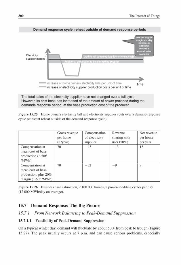
P1: TIX/XYZ P2: ABCJWST118-c15 JWST118-Hersent November 30, 2011 8:3 Printer Name: Yet to Come
300 The Internet of Things
Here the suppliermargin probably
increases asadditionaldemand is
sourced belowspot price
Additional consumption due to reheat cycle
Additional production to be planned by supplier
Demand response cycle, reheat outside of demand response periods
timeIncrease of home owners electricity bills per unit of timeIncrease of electricity supplier production costs per unit of time
The total sales of the electricity supplier have not changed over a full cycleHowever, its cost base has increased of the amount of power provided during thedemande response period, at the base production cost of the producer
Electricitysupplier margin
Figure 15.25 Home owners electricity bill and electricity supplier costs over a demand-responsecycle (constant reheat outside of the demand-response cycle).
Gross revenueper home(€/year)
Compensationof electricitysupplier
Revenuesharing withuser (50%)
Net revenueper homeper year
Compensation atmean cost of baseproduction (∼50€/MWh)
70 −43 −13 13
Compensation atmean cost of baseproduction, plus 20%margin (∼60€/MWh)
70 −52 −9 9
Figure 15.26 Business case estimation, 2 100 000 homes, 2 power-shedding cycles per day(12 000 MWh/day on average).
15.7 Demand Response: The Big Picture
15.7.1 From Network Balancing to Peak-Demand Suppression
15.7.1.1 Feasibility of Peak-Demand Suppression
On a typical winter day, demand will fluctuate by about 50% from peak to trough (Figure15.27). The peak usually occurs at 7 p.m. and can cause serious problems, especially

P1: TIX/XYZ P2: ABCJWST118-c15 JWST118-Hersent November 30, 2011 8:3 Printer Name: Yet to Come
The Smart Grid 301
68751 MW
45662 MW
00:00 4:00 8:00 12:00 16:00 20:00 24:00
Figure 15.27 Typical daily demand profile (from http://clients.rte-france.com/lang/fr/clients_consommateurs/vie/courbes.jsp).
during the coldest days: −1 ◦C adds about 2100 MW to the national consumption, ortwice the equivalent of the consumption of a large city for example, Marseilles (thissensitivity increases over time it was 1800 MW/◦C in 2006 and 1500 MW/◦C in 2000).Peak power consumption is in constant increase, and the trend is projected to continue :Figure 15.28 shows the forecast of RTE.
EDF, the incumbent national operator, decided to add, from 2006 to 2012, about 4000MW of ultrafast thermal production capability (e.g., fuel turbines) that can start andprovide power within 20 min. By comparison, an EPR nuclear reactor has a capacity ofabout 1600 MW. These turbines will be used typically less than a hundred hours per year.
The previous evaluations show that about 25% of homes using electric heating inFrance would need to participate in a demand-response program to completely balancethe network during the winter.
It is interesting to evaluate also what could be achieved if participation in a demandresponse program became mandatory by law for all users of electric heating (this policywould have some logic, considering the need to reduce CO2 emissions and the relativeinefficiency of the primary energy to electrical heating conversion).
Within the framework of a mandatory program, 6 million additional homes wouldcontribute to the peak-demand-suppression system, as well as a number of the 10 millionequivalent homes of the business sector.
If a single −1 ◦C demand-response cycle is allowed per day, each home (arbitrarilybased on our sample home, and increasing the base power production for the reheat cycles
2001 2002 2003 2004 2005 2006 2007 2008 2009 201579.6 79.7 83.5 81.4 86 86.3 59 84.4 91.5 (10/2009) 104 (forecast RTE 2009)
Figure 15.28 Peak consumption history in France and predictions (source RTE).

P1: TIX/XYZ P2: ABCJWST118-c15 JWST118-Hersent November 30, 2011 8:3 Printer Name: Yet to Come
302 The Internet of Things
as explained above) can provide about 6 kWh over less than 3 h, within an hour or less,with a peak of about 3.75 kW. Together, the 6 million homes provide a fast capacity ofover 30 GWh at a maximum power of 22 GW.
Most probably, the characteristics of our sample home do not reflect the averagecharacteristics of the entire French residential market. Still, our evaluation gives us anorder of magnitude that seems to clearly indicate that it is possible to completely replacethe additional fast production capabilities, characterized by an extremely poor CO2 perfor-mance for heating, by a voluntary expansion of demand response. The demand responseis also more flexible than additional power plants, as it can provide additional powerwhere it is required (e.g., in the often problematic western region of Brittany), withoutthe constraints of the underlying transport network (limited incremental capacity duringdemand peaks, power losses).
Beyond the suppression of extreme peaks, there seems to be ample potential to alsosignificantly smoothen the daily demand curve during winter: the portion of the demandbeyond the daily average represents about 80 GWh, out of which about 20 GWh forthe daily peak (Figure 15.27). From our evaluations above, it seems that the cumulatedcapacity of the 6 million homes would allow to shift about 30 GWh from peak to off-peak: enough to significantly flatten the daily demand curve, eliminating production andgrid-capacity issues while decreasing the CO2 emissions level and the average cost ofelectricity!
15.7.1.2 The Full Business Case of Demand Management
The business case associated to grid-balancing activities through demand shedding hasbeen evaluated above. The yearly revenues associated to this activity are very dependent onthe regulator decisions regarding the indemnification of additional costs of the electricityoperator: while a standalone network balancing activity appears very profitable under theassumption that additional energy costs are considered a mutualized grid managementcost, under any other assumption the yearly revenue per home is in the 10 to 20 €per yearrange, unlikely to justify the investments necessary for such an activity.
However, the potential of demand management goes beyond grid balancing. The costof electricity is highly variable, depending on the time of the day (Figure 15.29).Thesevarying prices simply reflect the market estimate of the instantaneous marginal productionprice of electricity.
As electricity operators consider that the demand side cannot be influenced, today’spredominantly fixed electricity residential prices simply reflect the average of the pricecurves weighted by the consumption profile of the customer.
This situation creates a significant opportunity for demand management. For each MWhof consumption “moved” from the peak hours to the lowest-cost hours the gain rangesfrom 40 up to 90 €! In the case of our sample home, a single demand shedding cycle of1 ◦C shifts about 6.2 kWh. If this shift is optimized properly to the least-cost hours: the

P1: TIX/XYZ P2: ABCJWST118-c15 JWST118-Hersent November 30, 2011 8:3 Printer Name: Yet to Come
The Smart Grid 303
0
Hour1
Hour 3A
Hour 5
Hour 7
Hour 9
Hour 11
Hour 13
Hour 15
Hour 17
Hour 19
Hour 21
Hour 23
20
40
60
80
100
120
140
01/2008
02/2008
03/2008
04/2008
05/2008
06/2008
07/2008
08/2008
09/2008
10/2008
11/2008
12/2008
Figure 15.29 EPEX spot prices depending on delivery hour, monthly averages (2008).
resulting gain for the operator is in the 0.25 to 0.50 €per day. This represents 5 to 10% ofthe final consumer bill, as well as a significant marketing advantage : the CO2 emissionmix of the electricity sold is also improved. Of course, the same demand-response systemsalso introduce a better regulation of energy in the home, resulting in additional savingsfor the consumer.
The first operators to fully exploit these possibilities will be able to lower the electricityprices and will become more competitive.
Demand-response flexibility goes both ways: it is also possible to increase demand.This will make it easier for operators to source wind energy and other renewable-energysources, as they will be able to temporarily “store” this randomly variable energy inthe homes of their customers, in the form of hot water, slightly higher temperature,and so on.
We believe that the market dynamics will then lead to the general adoption of demandmanagement, much in the same way as VoIP spread out from labs to every home in lessthan 10 years. In the same time frame, with the increasing penetration of electric cars,the potential of demand response – which will of course control the timing of batteryrecharging in homes and office parkings – becomes immense.

P1: TIX/XYZ P2: ABCJWST118-c15 JWST118-Hersent November 30, 2011 8:3 Printer Name: Yet to Come
304 The Internet of Things
15.7.2 Demand Response Beyond Heating Systems
So far, we have only evaluated the potential of heating control during winter. Clearly thescope of demand response applies to other uses of electricity as well. Here is a list of themost promising domains:
� Sanitary hot water. This is one of the most common uses of electricity, and also one ofthe most flexible ones as no one really cares when sanitary hot water is heated, as longas one can take a hot shower in the morning.
� Air-conditioning systems. With the ever-rising comfort standards, the use of air condi-tioning during summer is getting more common. Already, in some countries for example,in Italy, the yearly peak demand is during summer.
� Controlling public lighting. In France only, there are about 8.5 million lamps represent-ing 47% of the electricity bill of municipalities. Public lighting is notoriously inefficient,most lamps not only using obsolete technologies, but also wasting 30% of the energy tolight up the sky, and adding to the light pollution. Replacing these lamps will take timeand be very costly, however, a lot can be done to optimize the control of public lighting,such as using multilevel lighting (lower levels, e.g., one lamp out of two when there isno traffic and/or during peak power demand).
� Domestic and industrial refrigeration.� Electric and hybrid car battery-recharging control.
15.7.2.1 Sanitary Hot Water
We consider a hot water tank of 200 l, with a daily hot water usage of 150 l. Thiscorresponds to a daily water consumption of 500 l/day, with 50% warm water (warmwater is cold water mixed with 60% of hot water from the hot-water tank).
In order to heat these 150 l from about 10 ◦C to about 60 ◦C, about 8.7 kWh arenecessary each day. There are about 15% losses associated to thermal dissipation (thehot water temperature of sanitary hot-water tanks decreases by about 7 ◦C/day), thereforethe total energy consumption will be about 10 kWh each day, representing about3500 kWh/year. It is generally considered that the energy consumption for sanitary hotwater represents about 855 kWh per person per year, or about 25 kWh/m2. This alreadyrepresents about 10% of the total heating bill, but this share will increase in the future(see Figure 15.19).
The majority of sanitary hot-water tanks starts heating around 22:30, at the beginningof the reduced night tariff period. The heating period lasts about 4 h (4 × 2500 W = 10kWh).
15.7.2.2 Ventilation
In France, active ventilation systems are mandatory in new buildings since 1983. Mostsystems are single-flow ventilation systems which simply pump air from the house withouttrying to recover thermal energy.

P1: TIX/XYZ P2: ABCJWST118-c15 JWST118-Hersent November 30, 2011 8:3 Printer Name: Yet to Come
The Smart Grid 305
The fan engine has a power of about 50 W. An average ventilation system renews about30% of the building atmosphere per hour (this is extremely variable in a range of 10% to100%). For a 100 m2 house, with a volume of 250 m3, such an average ventilation systemwill pump out 75 m3 per hour. If T ref – Text = 10 ◦C, this represents a power loss of about325 W (plus the engine power).
The yearly energy loss caused by these simple ventilation systems represent about 2400kWh per year (1950 kWh of thermal losses, plus 450 kWh for the fan consumption).
During the public grid peak consumption periods, the outside temperature is below0 ◦C : the energy gain by stopping the ventilation system is about 700 watts (650 thermalloss watts, plus 50 watts for the fan consumption).
15.8 Conclusion: The Business Case of Demand Response and DemandShifting is a Key Driver for the Deployment of the Internet ofThings
For years, electricity operators have considered that demand was a random process gov-erned only by statistical laws. As a result, the electricity industry has developed extremelysophisticated strategies to adapt production to demand in real time. The costs associatedto this lack of control on demand are very high:
– dimensioning of public grids for peak transmissions;– building of “peak power” plants used only a few hours during the year;– extremely inefficient CO2 emissions during peak hours.
However, there was no easy alternative as electricity operators, despite early attempts withpowerline communications, never really developed a communication network capable ofmonitoring and controlling demand at the consumer level in real time.
With the ubiquitous presence of the Internet, it seems clear to us that times havechanged, and that the conditions are present for a fast deployment of demand-responsetechnologies, which seem to be capable of bringing considerable flexibility to today’s“statistical only” approach.
One of the interesting consequences of the development of demand response will be anincreased level of competition among electricity operators.
Today, all operators work from the same statistical models of demand, and use the samepower-plant technologies, facing identical costs. Competition is limited to limited mar-keting innovations and marginal production efficiency differences. If electricity operatorswere airlines, they would all be using the same planes, and there would be only one classof ticket: customers would choose according to seat color and meals.
After having deployed efficient demand-management tools, they will resemble moreclosely today’s airlines, using sophisticated yield management, several classes of tickets,low cost or business class only strategies. For airlines, this has resulted in a better usageof airplane, air traffic route and airport capacity, resulting in dramatically lower tariffs.

P1: TIX/XYZ P2: ABCJWST118-c15 JWST118-Hersent November 30, 2011 8:3 Printer Name: Yet to Come
306 The Internet of Things
For electricity operators too, the end result will be a maximization of the infrastructurepotential, and as a consequence lower costs and lower emission levels.
However, this communication network and home controllers, do have a cost. Deployingsuch networks and controllers in a silo mode (the initial temptation of all utilities andTSOs) is clearly not the optimal model. Instead, these smart-grid applications should beconsidered as applications of the Internet of Things: the communication network and thehome controllers should support general-purpose M2M communications and applications,decreasing the marginal cost (energy, amortization) of the smart-grid use cases. In orderto enable this infrastructure sharing, standards such as IP and ETSI M2M are critical: IPensures that the communication network is application and physical layer agnostic, ETSIM2M forms the middleware layer controlling the information flows: which applicationcan access which sensor/actuator, for which usage.

P1: TIX/XYZ P2: ABCJWST118-c16 JWST118-Hersent November 30, 2011 8:5 Printer Name: Yet to Come
16Electric Vehicle Charging
16.1 Charging Standards Overview
Until 2010, the standardization of EV charging addressed only very basic aspects, suchas how the vehicle should behave when it detects charging power or go back to sleepingmode when the charging power disappeared (IEC 61 681:2001). The plugs themselvesconformed to national standards (SAE J1772 shown in Figure 16.3, VDE-AR-E 2623-2-2/Mennekes shown in Figure 16.1, JARI/TEPCO), or to IEC industrial connector specifi-cations: IEC 62 196-1, single phase, for the US and Japan, and IEC 62 196-2 or 62 196-3(or 60309, see Figure 16.2) for Europe and China.
However, the standardization efforts for EV charging have intensified since 2008, andaddress mainly the following domains:
� The definition of a physical connector. On the EV side, the US and Japan haveconverged to the J1772 2010 plug (EV plug), which is now used by automakers Chrysler,Ford, GM, Honda, Mitsubishi, Renault-Nissan (Figure 16.5), Tesla, Toyota. Virtually allvehicles in production or planned in 2011 will use this plug. The J1772 plug is suitableonly for single-phase charging.
In Europe in the beginning of March 2011 there was still some debate between aEV plug format proposed by German manufacturer Mennekes, and a format proposedby Italian manufacturer Scame. The additional complexity comes from the fact thatthree-phase power is much more common in Europe and actually usable in many homesfor faster EV charging, and also from the various earth/ground connection regulations ineach European country. The final consensus seems to be that there will be two standardEV side connectors:
� Type 1 connectors, which are simply J1772 single-phase connectors with 5 pins, acharging voltage up to 250 V and charging current up to 32 A, that is, AC chargingpower up to 7 kW (full charge in 4 to 6 h, or 50 to 70 km per hour of charge).
The Internet of Things: Key Applications and Protocols, First Edition.Olivier Hersent, David Boswarthick and Omar Elloumi.© 2012 John Wiley & Sons, Ltd. Published 2012 by John Wiley & Sons, Ltd.

P1: TIX/XYZ P2: ABCJWST118-c16 JWST118-Hersent November 30, 2011 8:5 Printer Name: Yet to Come
308 The Internet of Things
Figure 16.1 Mennekes EV plug (IEC 62196 v2 candidate).1
� Type 2 connectors, originally proposed by Mennekes, which enable single- or three-phase charging with a charging voltage up to 500 V, and a charging current up to 63A (70 A for single-phase charging). Three-phase 400 V charging at 32 A represents acharging power of 22 kW (full charge in a couple hours, or 100 to 150 km per hour ofcharge).
In Europe, there is also a lot of activity regarding the definition of an EV chargingequipment (EVSE) side standard plug format, which would introduce some decouplingwith the EV side plug, as each car could use its own cable. As of May 2011, the proposalof the EVplug alliance seemed to have gained a wide consensus (Figure 16.4). This EVSEplug is also called the “type 3” plug.
At the international level, the current standardization converged so far only on therequirements (IEC 62 196-1:2003 Plugs, socket-outlets, vehicle couplers and vehicleinlets – Conductive charging of electric vehicles – Part 1: Charging of electric vehicles upto 250 A AC and 400 A DC).
Figure 16.2 IEC 60 309-2 3P+N+E, 9h plug.
1 Courtesy of loremo http://www.flickr.com/photos/loremo/3499948469/.

P1: TIX/XYZ P2: ABCJWST118-c16 JWST118-Hersent November 30, 2011 8:5 Printer Name: Yet to Come
Electric Vehicle Charging 309
Figure 16.3 SAE J1772 plug.
� Enhanced security. Early EV chargers relied only on traditional 30 mA differential cir-cuit breakers to detect current leakage. Modern EV chargers must have a dedicated pilotwire, which conforms to IEC 61 851:2010 (Electric vehicle conductive charging system –Part 1: General requirements), which implements proactive mass defect detection. Thisenhanced security mechanism is detailed in section “The IEC 61 851 pilot wire”.
� Basic charging power control by the charging infrastructure. IEC 61 851:2010 alsospecifies a simple pulse width modulation (PWM) protocol on the pilot wire enabling
Figure 16.4 Type 3 plug on one of the first EVplug alliance charging station, deployed in France.

P1: TIX/XYZ P2: ABCJWST118-c16 JWST118-Hersent November 30, 2011 8:5 Printer Name: Yet to Come
310 The Internet of Things
the EV charging equipment (EVSE) to communicate to the EV the maximum chargingcurrent allowed. The initial idea was to make sure that the EV would never draw exces-sive currents capable of causing fires in the charging infrastructure, but the mechanismcan also be used for admission control and demand response.
� Bidirectional charging control (DC charging). This functional area covers also thecommunication by the EV to the EVSE of EV requirements related to the charging ofthe EV battery by an external CC charger: like the constant current, constant power orconstant tension required (depending on the battery technology). There are no agreedinternational standards yet at this level, IEC 61 851-23 was not published as of March2011. The de-facto standard for existing vehicles is CHAdeMO, which uses dedicatedpins on the J1772 connector.
� High-level communication. This functional area encompasses the requirements forcharging control, but also covers security, charging and potentially many other services.At the international level, there are two standardization tracks: ZigBee SEP 2.0 (seeChapter 13), and IEC 15 118 (Road vehicles - Vehicle to grid communication interface).At the physical level, the proposals are to use IPv6 on top of Homeplug Greenphy, G3translated to the 150–450 kHz frequency band (300 to 400 kbit/s), or CAN (CHAdeMOproposal).
16.1.1 IEC Standards Related to EV Charging
The main IEC standard related to EV charging is IEC 61 851, managed by IEC TC 69.IEC 61 851 is split into several documents:
– Part 1: General requirements;– Part 21: Electric vehicle requirements;– Part 22: AC charging station requirements;– Part 23: DC charging station requirements;– Part 24: Communication protocol.
The IEC documents 3 cases for the physical connection:
– Case “A”: the cable and plug are attached to the EV.– Case “B”, the cable is detachable. In case B1 the cable connects to a standard domestic
plug, in case B2 the cable connects to a specific charging station. In practice, EVs soldin 2011 usually include a “B1” cable by default.
– Case “C”, the cable is attached to the EVSE.
The IEC also defines several charging modes. This nomenclature is now used by all EVSEvendors:

P1: TIX/XYZ P2: ABCJWST118-c16 JWST118-Hersent November 30, 2011 8:5 Printer Name: Yet to Come
Electric Vehicle Charging 311
– Mode 1 uses a standard 16 A socket outlet, single phase or 3-phase. The protectionagainst electric shock relies only on differential breakers in the charging infrastructureor in the cable. This charging mode is prohibited in the US, but outside of the US mostEVs currently circulating use mode 1 charging, and mode 1 charging is still proposedby default in many new EVs in 2011.
– Mode 2 still uses a standard 16 A or 32 A socket outlet on the charging infrastructureside, but uses a specific plug on the EV side. The cable must include a protectiondevice that implements proactive current-leakage detection through the pilot wire. Theadditional PWM communication over the pilot wire remains optional. This mode is thedefault for newer EVs in the US and Japan (the J1772 plug is used on the EV side), andis available as an optional cable for most recent EVs in other countries.
– Mode 3 requires a dedicated EVSE. The pilot wire that controls the charging sessionis managed by the EVSE. No charging power is available over the charging cable untilthe EV has been detected by the pilot wire and the absence of current leaks or grounddefects has been verified. The pilot wire also optionally indicates the maximum chargelevel by using PWM modulation: 16 A (normal), 32 A (semifast), > 32 A (fast). Mode3 is safer than mode 1 or 2, because the plug is energized only if all of the followingconditions are met:� the vehicle power plug is totally inserted (the pilot pin is last to connect);� ground continuity has been checked (pilot current present);� the vehicle has transmitted a signal confirming that everything is secured and charging
is ready to begin.– Mode 4 applies to external chargers (e.g., DC charging) and also covers the inverse
mode where the EV provides power to the charging infrastructure. This mode, coveredby IEC 61 851-23, was not fully specified as of March 2011. It requires a serialbidirectional communication over the pilot wire.
In practice, the new EVs sold in 2011 usually had two plugs, a standard domestic maleplug for mode 1, and a J1772 or equivalent plug for modes 2 and 3 charging (Figure 16.5).
16.1.1.1 The IEC 61 851 Pilot Wire
IEC 61 851:2001 requires for mode 2, 3 and 4 charging a dedicated “pilot wire” in theEV plug. This pilot wire is connected by a 1000 Ohm resistor to the mass (ground) of thevehicle and a weak current circulates from the pilot wire to the ground of the connectorin order to test the correct grounding of the EV.
The new IEC 61 851-1 (edition 2 of November 2010) introduces an additional controlfunction, and documents in annexes A and C a (non-normative) PWM protocol for thepilot wire (Figure 16.6).
In Figure 16.6, the EV indicates that it is ready to begin a charge session by closingswitch S2, which changes the voltage measured at point Va. On the EVSE side, the duty

P1: TIX/XYZ P2: ABCJWST118-c16 JWST118-Hersent November 30, 2011 8:5 Printer Name: Yet to Come
312 The Internet of Things
Figure 16.5 J1772 (type 1) connector on a Renault EV.
cycle of signal Vg indicates the maximum current that the EV is allowed to draw fromthe EVSE at any moment: no charging for a duty cycle lower than 3%, and then any valuefrom 6 to 80 A coded by a duty cycle above 8%. A special value of the duty cycle of 5%indicates that a digital communication (“high-level communication”) is used instead.
The standard indicates that the dedicated pilot function could be replaced by a currentmodulation on the ground conductor (61851-1ed2, Appendix C), without defining it yet.
In this new version, the mandatory EVSE/charging cable functions for charging modes2, 3 and 4 are:
– the verification that the EV is connected;– continuous control of the correct grounding of the EV;– energization and de-energization of the EV.
Vehicle EVSE
1kΩ (3%)
274k
Ω(3%
)
1,3k
Ω(3%
)
Earth (Ground)
Pilot Contact
CsOscillator1 kHz ± 12 V
Voltage measurement(Va)
(Vg)
Duty cycle andFrequencymeasurement(Vb)
S2
Figure 16.6 Pilot wire circuit, according to IEC 61851 and J1772.

P1: TIX/XYZ P2: ABCJWST118-c16 JWST118-Hersent November 30, 2011 8:5 Printer Name: Yet to Come
Electric Vehicle Charging 313
The new optional functions are:
– selection of the charging power;– determination of the ventilation requirements of the charging area;– bidirectional power control (not yet specified in edition 2 of IEC 61851).
16.1.1.2 High-Level Communication: IEC 15 118
IEC 15 118 Road vehicles - Vehicle to grid communication interface was still a work inprogress at the time of writing. This standard is managed by ISO/TC 22 (Road vehicles)jointly with IEC TC69.
� IEC 15 118-1 “General information and use-case definition” defines the vocabularyused in other parts of the standard, and focuses on the use cases for high-level com-munications between the electric vehicle communication controller (EVCC) and thesupply equipment communication controller (SECC). Both online (Figure 16.8, SECCconnected to the E-Mobility operator by a communication network as the service isprovided) and semi-online (Figure 16.7, SECC-E-mobility provider communication is
Vehicle EVSE ProviderEnergy Provider with Control and Billing Func�onality, Clearinghouse, Charge Spot Provider
Exchange of security informa�on (CRL updates, cer�ficates….)
Connec�on
TLS session establishment
Exchange of security related informa�on (CRL updates, EVSE cer�ficate)
Service discovery
Power discovery and delivery
Meter reading R(t0) for charging period t0
Signed Meter reading R(t0)
Meter reading R(tn) for charging period t0
Signed Meter reading R(tn)
Charging finished
Connec�on termina�on
Chargingcycle
Exchange of signed chargingrecords (via a network of offline)
Figure 16.7 Overview of IEC 15 118-2 charging session semionline protocol flows.

P1: TIX/XYZ P2: ABCJWST118-c16 JWST118-Hersent November 30, 2011 8:5 Printer Name: Yet to Come
314 The Internet of Things
Vehicle EVSE ProviderEnergy Provider with Control and Billing Func�onality, Clearinghouse, Charge Spot Provider
Exchange of security informa�on (CRL updates, cer�ficates….)
Connec�on
TLS session establishment
Exchange of security related informa�on (CRL updates, EVSE cer�ficate)
Service discovery
Connec�on termina�on
Charging req. (ContractID,vehicle cer�ficate)
Token(chargingplan, tarif) encrypted with vehicle cer�ficate
CHARGING CYCLE(same as semi-online case)
Token (charging plan, tarif) encrypted with vehicle cer�ficate
Charging plan selec�on (chargePlanID)Chargingplan selec�on(chargePlanID) May be updated by vehicle during charging session
Last signed Meter reading R(tn)
Figure 16.8 Overview of IEC 15 118-2 charging session online protocol flows.
not synchronous with the service provided) use cases are defined. IEC 15 118-1 definesfour identifiers:� SECC Spot Operator ID: the unique identification of the spot operator that provides
the energy to the vehicle.� SECC Power Outlet ID: the unique identification of the power outlet to the vehicle.� EVCC Provider ID: the unique identification of the contract between the vehicle user
or the vehicle itself and the energy provider given by the E-mobility operator. TheE-mobility operator is defined as “the legal entity that the customer has a contractwith for all services related to the EV operation”.
� EVCC Contract ID: it identifies the contract that will be used by the SECC toenable charging and related services (incl. billing). It is associated with the electricityconsumer (who can be the driver, the owner of the vehicle or a E-mobility operator).
� Session ID: the identifier of the charging or value added service session, obtainedafter the authentication procedure.
� IEC 15 118-2 “Technical protocol description and open systems interconnections (OSI)requirements”, defines an application layer protocol on top of IPv6 (optionally IPv4)between the SECC and the EVCC. The communication uses a TCP connection secured

P1: TIX/XYZ P2: ABCJWST118-c16 JWST118-Hersent November 30, 2011 8:5 Printer Name: Yet to Come
Electric Vehicle Charging 315
PT PL PAYLOAD
Protocol version0x01 V2GTP v1
Bit inverse protocolversion
0xFE for V2GTP v1
Payload type
Payload length(bytes excl. Header)
0x0000 Nega�ve Ack
0x0001 Alive check Req
0x0002 Alive check Resp.
0x8001 XML encoded V2G message
0x8002 EXI encoded V2G message
>0x8003 Manuf. extensions
Figure 16.9 V2GTP header structure and example XML payload.
by TLS, the SECC acting as the TLS server, and uses the vehicle to grid transfer protocol(V2GTP) defined in IEC 15 118-2 (see below for more details on V2GTP). the SECCdiscovery protocol (SDP)
� IEC 15 118-3 “Physical and data link layer requirements”, will define the physical layersupporting the IP connectivity for the V2G protocol. It was not stable at the time ofwriting this document, although it seemed that PLC HomePlug GreenPhy technology(refer to the PLC chapter) had the best chance of being selected.
The V2GTP session is bootstrapped using the SECC discovery protocol (SDP). The EVbegins by multicasting a UDP_SECC_LISTEN message to port 15 118 (!) as a means ofdiscovering the SECC. The EVSe generates a random sessionID or provides the last validsessionID if this is an attempt to resume a session. The SECC, if any, will respond to thesource UDP port with a SECC discover response message, which specifies the server-sideTCP port for the V2GTP session.
As V2GTP uses a TCP connection (which is stream oriented) to transport messages, itneeds a framing mechanism. The V2GTP header (Figure 16.9) serves this purpose.
V2GTP defines an XML message set, which can be encrypted and signed using acertificate bound to a given contractID (current status at the time of writing). All messageshave a common header format that carries the session ID.
The V2G protocol session is organized as follows:
Initialization of communication session: after session bootstrapping with the SECCdiscovery protocol and TLS session setup, the following messages are exchanged:� SupportedAppProtocolRequest/Response: EVSE and EVCC exchange-supported
protocol major/minor versions, associated namespaces and preference order.

P1: TIX/XYZ P2: ABCJWST118-c16 JWST118-Hersent November 30, 2011 8:5 Printer Name: Yet to Come
316 The Internet of Things
� Session Setup Request/Response: the plug-in EV (PEV) specifies the PEV MACaddress (PEVID) and PEV status code. The EVSE replies with a response code, anEVSEID and status code.
Service Discovery: Discover the services offered by the EVSE. Messages for thisactivity:� Service Discovery Request/Response: the EV Service Discovery Request specifies
the service scope (one or more URIs, each corresponding to a service provider), andoptionally service type (e.g., charging, Internet access). The EVSE response specifiesa list of supported services.
� Service Selection Payment Request/Response: the EV selects services and corre-sponding payment options in the service selection payment request, and the EVSEvalidates each service/payment option selected.
� Payment Details Request/Response: So far, only the details corresponding to pay-ment method “contract” are specified. The EV sends a contractID, and the signaturecertificate chain of the EV. The EVSE responds with a random challenge that has tobe signed by the EV.
� Contract Authentication Request: the EV sends a copy of the challenge and itssignature, and the EVSE answers with a response code.
Charge vehicle: charging the EV is one possible service offered by the EVSE. It isdivided into three phases:
(1) Set up charging process:� Charge Parameter Discovery Request/Response: the PEV provides status in-
formation, charging mode (DC or AC), desired point in time for the end of charge,estimation of required recharge energy, maximum charge power, maximum chargevoltage, minimum charge voltage, maximum number of charge phases, maximumcharge current and minimum charge current. The EVSE responds with its statusinformation and provides its own charging-limit parameters, as well as the identityof the relevant mobility/energy provider and a tariff table (Figure 16.10).
� Line Lock Request/Response: EV requests the EVSE to lock the connector onthe EVSE side and specifies its own lock status.
� Power Delivery Request/Response: the PEV requests the EVSE to start providingcharging power, specifies the selected tariff and optionally transmits the estimatedcharging profile (Figure 16.11) it will follow during the charging process. TheEVSE replies with a response code.
TariffEntryTariffTable
TariffStartTariffPMax
Eprice
CurrencyTariff
EPriceUnitEPriceMul�plier
TariffDescrip�on
TariffIDTariffDescrip�on
TariffEntriesUp to 6
Up to 24
Figure 16.10 TariffTable structure IEC15118 draft (may 2011).

P1: TIX/XYZ P2: ABCJWST118-c16 JWST118-Hersent November 30, 2011 8:5 Printer Name: Yet to Come
Electric Vehicle Charging 317
ChargingProfile
ChargingProfileEntrystartChargingProfileEntryMaxPower
Up
to12
8
�me
MaxPower
ChargingProfileEntryStart
ChargingProfileMaxPower
Figure 16.11 Charging profile structure in current IEC 15 118 draft (May 2011).
� Metering Status Request/Response: the EV request the EVSE to send its currentmetering status. The response of the EVSE contains a timestamp, an instantaneousestimate of the power the EVSE could deliver, optionally the current power it isdelivering, a meterID and current metering information.
� Metering Receipt Request/Response: the EV Metering Receipt Request con-tains the electronic signature of the following information elements: sessionID,MeterInfo, PEVstatus, time stamp, tariffID, metering information. This informa-tion ensures nonrepudiation for the billing process of the E-mobility provider. TheEVSE acknowledges with a response code.
(2) Charging process: periodic metering status request/response and metering re-ceipt request/response (the draft standard mentions a periodicity of about 10 s),and if needed charge parameter discovery request/response and power delivery re-quest/response.
(3) Finalize charging process: stop charging process (final power delivery re-quest/response, metering status request/response, metering receipt request/response),unlock charge cord with line lock request/response.
At the time of writing (May 2011), there were some discussion ongoing as to whetherto continue investigating a separate XML message set, or to use the ZigBee SEP 2.0.The openV2G project (http://openv2g.sourceforge.net/) is implementing both solutions.One of the issues is that the current design of V2GTP follows the style that was usedin the 1990s for telecom protocols (e.g., H.323 for VoIP), and is not aligned with theresource-based (REST) programming style used by most recent protocols (ZigBee SE2.0,ETSI M2M . . .). This means that, as outlined in the current draft, V2GTP will not be ableto leverage modern protocols designed for REST applications, like CoAP or HTTP.
16.1.2 SAE Standards
16.1.2.1 J1772 “Communications Between Plug-In Vehicles and the Utility Grid”
The original J1772 plug format was designed in 1996 by Japanese manufacturer Yazaki,and adopted by the SAE hybrid standard committee in 2001. This document defines the

P1: TIX/XYZ P2: ABCJWST118-c16 JWST118-Hersent November 30, 2011 8:5 Printer Name: Yet to Come
318 The Internet of Things
Pin 1 : L1
Pin 5 : proximitydetec�on
Pin 3 : Ground
Pin 2 : L2/N
Pin 4 : Control pilot
Figure 16.12 J1772 plug, and typical US residential wiring.
physical format of the EV plug for AC charging and addresses basic security and powercontrol requirements by means of a proximity detector pin and a control pilot pin.
The original J1772:2001 specification used 9 pins, plus a proximity detector. 2 pinswere used for DC charging up to 400 A, 2 pins for AC charging up to 40 A, 1 ground pin,1 control pilot pin, and 3 pins for SAE J1850 data transmission. A magnetic proximitydetector switch was provided on the EV side to prevent motion during charging.
J1772 was revised on January 2010. The J1772:2010 connector, illustrated onFigure 16.12, only uses 5 pins: two pins for single phase AC charging up to 80 A, oneground pin, one pilot wire pin, and one proximity detector pin. The proximity detector pinis connected to the ground via a resistor network in the plug, the resistor value changeswhen the latch release switch of the plug is pressed, signaling that the plug is about toget disconnected. The control pilot protocol is identical to that of IEC. The proximitydetector and pilot wire pins are shorter, so that they connect last and disconnect first. The3 dedicated pins provided by J1772:2001 were removed as SAE now plans to use PLCfor high-level communications.
J1772 defines 3 charge levels:
– “Level 1”: charge via a charge cable including the pilot wire control equipment (“mobileEVSE”), connected to a US domestic plug (single-phase 120 V/15–20 A).
– “Level 2”: charging via a fixed EVSE station connected to a 240 V single phase, up to80 A.
– “DC charging”, using an off-board charger.
16.1.3 J2293
Task force J2293 of the SAE is focused on the standardization of EVs and the communi-cation between the EV and the EVSE. It initially addressed both conductive and inductivecharging, but inductive charging (J1773) is no longer considered. The J1772 standard,

P1: TIX/XYZ P2: ABCJWST118-c16 JWST118-Hersent November 30, 2011 8:5 Printer Name: Yet to Come
Electric Vehicle Charging 319
which focuses on conductive charging, implements the same pilot wire mechanism asthe IEC.
The 2008 version of J22932 described a high-level charging protocol based on theJ1850 serial communication protocol, which has never really been used and was formallymade obsolete in 2010.
The SAE worked on a comprehensive list of use cases for EV charging, published asJ2836/1 (a 244 page document!) in April 2010.
The SAE then worked on a revised architecture and communication protocol supportingall these use cases, and considered two options for the high-level communication protocol:
– The CAN bus that is adopted is all modern vehicles, but would need a specific messageset to support EV charging.
– IPv6 and the ZigBee SEP 2.0 REST data model. Initially both 6LoWPAN over 802.15.4and IPv6 over CPL were considered, at present it seems the SAE is focusing on IPv6over CPL, most likely HomePlug GreenPhy (see Chapter 2).
This revised architecture was published in June 2010 as J2847-1 “Communication betweenthe Plug-in vehicle and the utility grid” and J2847-2 “Communication between Plug-inVehicles and the Supply”(which adds a message set to support DC charging and replacesJ2293). Both documents are based on ZigBee SEP 2.0 (see Chapter 13).
16.1.4 CAN – Bus
The CAN bus is a proprietary protocol designed by Bosch GmbH in 1983, which wasthen published at SAE in 1986. CAN 2.0 was published in 1991, and uses an expanded29-bit identifier format.
CAN is a half-duplex multimaster broadcast serial bus using NRZ encoding. Originally,only the interface to the physical layer was specified, but most recent CAN implementa-tions rely on the physical layer specified by ISO 11 898-2:2003 (“Road vehicles -Controllerarea network (CAN) - Part 2: High-speed medium access unit”) or ISO 11 898-5:2007(“Road vehicles - Controller area network (CAN) - Part 5: High-speed medium accessunit with low-power mode”). The achievable bitrate varies between 1 Mbit/s (distancesup to 40 m with ISO 11 898-2 or -5) and 125 kbit/s (distance up to 500 m with ISO 11898-3).
The CAN data link layer uses ISO 11 898-1:2003 (“Road vehicles – Controller areanetwork (CAN) – Part 1: Data link layer and physical signaling”), which specifies themedium access control sublayer and the logical link control sublayer. The MAC sublayerimplements a CSMA collision avoidance mechanism: all messages begin with an ID,
2 J2293-1 “Energy Transfer system for Electric Vehicles – part 1: Functional Requirements and system Archi-tectures”, and J2293-2 “Energy Transfer system for Electric Vehicles – part 2: Communication Requirementsand Network Architecture”.

P1: TIX/XYZ P2: ABCJWST118-c16 JWST118-Hersent November 30, 2011 8:5 Printer Name: Yet to Come
320 The Internet of Things
which also encodes the priority level: in case a “1” and a “0” are simultaneously transmittedon the bus, only value “0” will be sensed by all nodes in the network. The node that hadjust transmitted a “1” then knows a collision has occurred and stops transmitting. Theoriginal CAN and CAN 2.0A specification uses an 11-bit identifier field. On recent CAN2.0 implementations using a 29-bit identifier structure: the first 3 bits are reserved for thepriority level, the next 18 bits encode the frame format (broadcast or unicast parametergroup, and 8-bit destination address/group), the last 8 bits encode the sender address.
The ID field is followed by up to 8 payload bytes. Any higher-layer protocol may beused on top of CAN, for instance:
– The ISO transport protocol (ISO TP, 15 765-2) is used by existing diagnostics protocolson CAN (e.g., ISO 14230), and provides segmentation (transmission of up to 4095bytes), flow control, broadcast and unicast addressing. Error recovery is left to theapplication layer.
– TP 2.0 that adds automatic error recovery (mainly used by Volkswagen).– CAN Open, developed by Bosch GmbH and handed over to CAN in Automation user
group (http://www.can-cia.org/) in 1995. It was standardized as EN 50 235-4 in 2002,which defines a object dictionary enabling cross-manufacturer compatibility.
– SAE J1939, which defines a segmentation and flow control mechanism, and an appli-cation layer for buses, trucks, and agricultural equipment.
At present, there is no proposal to port 6LoWPAN over CAN, which means the CANoption for EV to EVSE communication would not be IP based and would serve only forlow-level control purposes. This is considered problematic by some car manufacturerswho believe the EV to EVSE connection may be leveraged also for other uses, for example,downloading movies while charging, and in general would require the versatility of IP.
CAN, which was designed for closed systems, also lacks a set of specifications forstrong authentication and security, which are required for communications between theEV and EVSE.
16.1.5 J2847: The New “Recommended Practice” for High-LevelCommunication Leveraging the ZigBee Smart Energy Profile 2.0
The J2847 series is the result of joint work since 2009 between SAE and the ZigBee andHomePlug alliances, with the following objectives:
– defining a message set that would support the requirements of J2836/1;– integrate with home area networks and utility networks;– follow the REST model recommended by the NIST, and be based on IPv6.
Because the high-level communication is based on IPv6, any underlying transport layersupporting IPv6 might be used. The REST interactions might be transported by HTTP

P1: TIX/XYZ P2: ABCJWST118-c16 JWST118-Hersent November 30, 2011 8:5 Printer Name: Yet to Come
Electric Vehicle Charging 321
over IPv6 for high-speed physical layers such as HomePlug GreenPhy or G3, or by CoAPover 6LoWPAN for lower-speed physical layers such as 802.15.4 or low-energy CPL.Refer to Chapter 2 for more details on CPL technologies.
The original ZigBee SEP 2.0 specification does not address the EV charging use caseonly, therefore the SAE reworked the specification and split it in several documentsfocused on the specific requirements for EV charging:
� J2847/Part 1 “Communication between Plug-in Vehicles and the Utility grid” lists themessages used to support the J2836/1 baseline requirements:– vehicle, customer, evse identification and authentication;– energy request management (energy and power requests, energy and power manage-
ment and scheduling);– timing information (start and stop time, anticipated duration, charging profile, actual
start time);– pricing, including time of use pricing, critical peak pricing;– load control (demand response, load shifting);– vehicle information and status.
The other J2847 documents were not published at the time of writing:� J2847/Part 2 “Communication between Plug-in Vehicles and the Supply” will replace
the high-level messages specified in J2293 for the specific use case of DC charging.� J2847/Part 3 will focus on the Reverse Power Flow (RPF) use case, that is, when the
EV provides energy to the utility network.� J2847/Part 4 will focus on charging system and EV diagnostics.� J2847/Part 5 will focus on vendor-specific extensions and options.
16.2 Use Cases
16.2.1 Basic Use Cases
The basic use case is, of course, the charging of the EV battery. The battery of a plug-inhybrid electric vehicle (PHEV) has a capacity of typically 5 to 6 times the capacity of ahybrid electric vehicle (HEV). The capacity of the battery of pure battery electric vehicles(BEV) is 3 times or more that of PHEVs (see Figure 16.13).
In order to allow for reasonable charging times, the charging power and current istypically 16 A or more. For an isolated home, this is enough to require load managementand limiting in order to avoid simultaneous use of other high-power appliances, such aselectric heating and sanitary water, electric ovens, and so on. In a residential complex, thesimultaneous charging of several plug-in vehicles will also require careful synchronizationof management in order to ensure fair charging of all vehicles, without exceeding the powerlimits of the connection between the building and the utility grid.
In both cases, this means that charging stations at home or in the work place will eitherrequire a separate utility connection (as in the case of Italy where most existing residential

P1: TIX/XYZ P2: ABCJWST118-c16 JWST118-Hersent November 30, 2011 8:5 Printer Name: Yet to Come
322 The Internet of Things
PHEV15 PHEV40 BEV
Ba�ery capacity (kWh) 5 16 24
1.4 kW (16 AWG) 2 h 50 mn 9 h 10 mn 13 h 45 mn
3.3 kW (16 AWG) 1 h 15 mn 3 h 50 mn 5 h 50 mn
7 kW (8 AWG) 35 mn 1 h 50 mn 2 h 45 mn
19.2 kW (8 AWG) 15 mn 40 mn 1 h
Char
ging
�m
e (2
0% to
100
%)
60 kW (4 AWG) 5 mn 15 mn 20 mn
Charge-deple�ng range or All Electric mode range
23 km–15 miles 64 km–40 miles 160 km–100 miles
Figure 16.13 Typical battery capacity and charging time of EVs.
electric connections cannot deliver more than 3 kW), or will need to be integrated in thelocal energy-management system. The latter is expected in all countries where the cost ofupgrading the capacity of the existing home connection is lower than the cost of a newconnection to the utility grid (e.g., in France where a new connection is charged about1000€ in the best cases, and much more depending on the distance between the homeand the closest distribution operator street cabinet).
Considering only the short term, EVs are beneficial for the stability of the electric grid.All transmission system operators (TSOs) face short-term mismatch problems betweenpower production and demand (see Section 14.4 for more details). The charging power ofEVs can be adapted in real time by using the pilot wire, and provide an ideal flexible loadfor demand-response policies.
Unfortunately, the EV is also problematic for utilities: EVs are ideal vehicles forcommuters who run short distances between their work place and home. This meansthat the charging load will exhibit a pendular behavior as well: large and sudden charg-ing requirement peaks in the suburbs after work hours and in business districts in themorning. However, since the midterm (hourly) pattern of such demand is predictable,utilities with smart-grid capabilities may implement load-shifting and load-capping poli-cies to smooth the total demand in a given district: for instance the HVAC installa-tions of business centers may be programmed to reach their setpoints just before therush hour, possibly to slightly exceed the heating setpoint during winter and coolingsetpoint during winter so that additional energy can be delivered to the EVs during acouple hours.
The basic capability provided by the pilot wire PWM charging rate control is sufficientto implement load limiting, load shifting and demand response, if all vehicles are treatedthe same, and of course in the specific case of a single home with a single car.

P1: TIX/XYZ P2: ABCJWST118-c16 JWST118-Hersent November 30, 2011 8:5 Printer Name: Yet to Come
Electric Vehicle Charging 323
However, not all vehicles have the same needs:
– The battery of some vehicles may be charged at 90% of capacity already, while othercars may be at a critical battery level.
– Some vehicles may need to depart within the next hour, while other vehicles will notmove for 8 h or more.
– Some users may be willing to pay more to be served in priority.
These examples show that more sophisticated arbitration policies that seek to optimize theaggregate satisfaction of users need more information on each EV state and requirements:the high-level communication protocol, such as ZigBee SEP 2.0/J2847, will become amandatory feature as soon as EVs reach a penetration that make it very likely to have 5EVs or more (including rechargeable hybrids) simultaneously connected in an office orresidential complex parking, this is probably as soon as 2015!
16.2.2 A More Complex Use Case: Thermal Preconditioning of the Car
Traditional thermal engines have a nice side effect: heating is provided “for free”. How-ever during hot summer days, we have all noticed how air conditioning affects the carperformance and consumption.
This air-conditioning tax will be a burden for EVs, both during summer and winter.As much as 30% of the total energy of the battery may be spent by air conditioning, andmuch of it during the first 10 min for the initial conditioning: typically 6 kW for 10 minand 2 kW afterwards for heating, 3 to 4 kW initially then 2 kW for cooling.
In order to minimize this problem, a possible strategy is to precondition the car. Astudy published in November. 2010 by the US National Renewable Laboratory (NREL)3
quantified the improvement of preconditioning for several types of cars. The resultsprovided in Figure 16.14 assume a mixed drive cycle of 55% city driving, and 45%highway driving. The impact of preheating would be even more favorable for shortcommuting cycles.
Of course, in addition to the increased range and reduced fuel consumption, the levelof comfort is also improved by preconditioning.
This more complex use case shows that the communication protocols for future chargingsystems may need additional parameters, such as:
– The estimate of the preconditioning energy and power schedule, including the initialhigh-power conditioning and the ongoing conditioning. This should be calculated bythe car based on external temperature measurement and air-conditioning setpoints.
– The preconditioning schedule, for example, when preconditioning is scheduled to begin.– Whether or not the user charging profile allows preconditioning.
3 “Analysis of Off-Board Powered Thermal Preconditioning in Electric Drive Vehicles” available athttp://www.nrel.gov/vehiclesandfuels/vsa/pdfs/49252.pdf.

P1: TIX/XYZ P2: ABCJWST118-c16 JWST118-Hersent November 30, 2011 8:5 Printer Name: Yet to Come
324 The Internet of Things
Charge-deple�ng (CD) or All-electric range (AER) reduc�on (addi�onal fuel consump�on)
Range increase by 20 mn precondi�oning (compared to no pre condi�oning)
Car category Hea�ng (–6°C ambient temperature)
Cooling (+35°C ambient temperature)
Hea�ng (–6°C ambient temperature)
Cooling (+35°C ambient temperature)
100 mile BEV (e.g., Nissan Leaf)
–34% –32% +4% +2%
40 miles PHEV (e.g., GM Volt)
–35% (+60% fuel) –34% (+57% fuel) +6% (–3% fuel) +4% (–1%)
15 mile PHEV (e.g., Toyota Prius)
–19% (+3% fuel) –32% (+49%) +19% (–1% fuel) +5% (–1% fuel)
Figure 16.14 Effect of air conditioning on range (55% city, 45% highway driving), from NRELstudy.
16.3 Conclusion
The need for communication systems in the car goes much beyond EV charging. Thepotential for M2M service providers is enormous: there are about 50 million cars producedin the world each year, for a total of over 600 million in circulation.
The European eCall directive, which mandates installation of automatic emergencycalling in new cars as of 2014, has made it mandatory to install a cellular communicationplatform in all new European cars. Building on this, most automakers are now planningto use this cellular communication platform to implement a M2M GPRS connection formaintenance and monitoring of the vehicle. Such systems are already in place in all newEVs and will soon generalize to all new cars.
What is the next step? Automakers will soon provide on-board IP connectivity for the carappliances (GPS systems for instance). It would make no sense to build separate verticalsystems for EV charging, car monitoring, and on-board M2M connectivity. Clearly, ourvehicles will need to provide a generic M2M infrastructure able to leverage both thecellular network and IP connectivity provided through charging stations (or, in the future,by parking lots). With this in mind, we believe that the protocols as defined currently willneed to evolve:
– IEC15118 current draft is “too vertical” but explores in details all the semantics for EVcharging in the context of a multiactor deployment.
– ZigBee SE 2.0 is REST-based and a little more generic, but still focused on energymanagement. Multiactor interactions are not as clearly defined as in IEC 15 118.

P1: TIX/XYZ P2: ABCJWST118-c16 JWST118-Hersent November 30, 2011 8:5 Printer Name: Yet to Come
Electric Vehicle Charging 325
ETSI M2M (see the ETSI M2M chapter) provides a generic REST framework for M2M,but so far no detailed work has been done to explore how the semantics of IEC15118 andSE2.0 could be integrated in this framework. The authors believe, however, that this isa very promising direction. The future communication architecture of our cars probablywill need the use case versatility of frameworks such as ETSI M2M, complemented byspecific interworking profiles for charging specific “REST resources” like those definedby IEC15118 and SE2.0. If that happens, EV charging “protocol” specifications shouldevolve into “REST resources” specifications, leaving the plumbing to other, more generic,protocols.

P1: TIX/XYZ P2: ABCJWST118-bapp01 JWST118-Hersent November 30, 2011 8:7 Printer Name: Yet to Come
Appendix ANormal Aggregate Power Demandof a Set of Identical HeatingSystems with Hysteresis
For simplification, we suppose that weather conditions remain constant and that thetemperature evolution curve in all homes is a zig-zag function of time (Figure A.1):when the heating system is on, the temperature increases by X ◦C/hour, when it is off,it decreases by Y ◦C per hour. All homes are equipped with a traditional thermostat thatregulates the temperature with a hysteresis of H ◦C: the heating system is switched onwhen the temperature reaches T ref, and switched off when it reaches T ref + H. In reality,these temperature evolution curves are exponential functions of time, but this linearapproximation is valid if H is small compared to the T ref–Text, the temperature gradientbetween the inside and the outside of the house walls. The heating system thereforeremains switched on for H/X hours (the part of the zig-zag during which temperatureincreases), and then remains switched off for H/Y hours (the part of the zig-zag duringwhich temperature decreases).
We further suppose that initially thermostats are not correlated: at any moment, if wesort homes according to the last time the heating system was switched on, an identicalnumber k.δt of homes had their heating system last switched on between T and T + δt. Notethat the last time the heating system was switched on at any time T must be within interval[T–H/X–H/Y , T], therefore we can write the total number of homes as N = k(H/X +H/Y).
Let us calculate the number of heating systems that are switched on at any point in timeT: the moment they have been last switched on must be in interval [T–H/X, T], thereforewe have k.H/X heating systems switched on.
The Internet of Things: Key Applications and Protocols, First Edition.Olivier Hersent, David Boswarthick and Omar Elloumi.© 2012 John Wiley & Sons, Ltd. Published 2012 by John Wiley & Sons, Ltd.

P1: TIX/XYZ P2: ABCJWST118-bapp01 JWST118-Hersent November 30, 2011 8:7 Printer Name: Yet to Come
328 The Internet of Things
Tref
Tref -
Thermostats are offset from
Tref to Tref -
MW
~ /Y
+X°C/hour
-Y°C/hour
Tref+H-
~H/X
Tref+H
~H/Y
~H/Y+H/X
time
time
Figure A.1 Evolution of power demand after a synchronized thermostat offset.
If we call Pmax the cumulative power demand of all homes if they all had they heatingsystems switched on, the average aggregate power demand of a set of homes withdecorrelated thermostats is P = Pmax(H/X)/(H/X + H/Y) = PmaxY/(X + Y).
Normal aggregate power demand of a set of homes withdecorrelated thermostats:
P = PmaxY/(X + Y ).

P1: TIX/XYZ P2: ABCJWST118-bapp02 JWST118-Hersent November 26, 2011 16:55 Printer Name: Yet to Come
Appendix BEffect of a Decrease of Tref.The Danger of Correlation
If we decrease T ref by � ◦C at time 0, the effect on power demand depends on ourthermostat strategy:
� We may switch off all heating systems (as by definition, all homes have a currenttemperature greater than T ref, therefore also greater than T ref−�): the aggregate powerdemand of our homes instantaneously falls to zero.
� As the new hysteresis settings of our thermostat is now [Tref − �, Tref + H − �], ifH > � some homes have a current temperature in interval [Tref, Tref + H − �]. We canchoose to heat some or all of these homes up to Tref + H − �, maintaining residualpower demand.
Let’s choose the first strategy and evaluate its effects:
� Power demand will fall to 0 for �/Y hours: this duration represents the time it takes forthe homes that were coldest (at T ref) when the thermostat setting was changed to reachT ref − �.
� After �/H hours, heating systems are switched back on in an increasing number ofhomes. At time �/H + t, the heating systems of all homes that reached temperatureT ref − � between time �/H and time �/H + t are switched on, that is, homes that hada temperature between T ref and Tref + Yt(t < H/Y ) when we changed the thermostatsettings. These homes fall into two categories:� Homes that were in “cooling down” mode, the heating systems of which were last
turned on in the interval [−H/X−H/Y , −H/X−H/Y + t]: there are kt such homes.
The Internet of Things: Key Applications and Protocols, First Edition.Olivier Hersent, David Boswarthick and Omar Elloumi.© 2012 John Wiley & Sons, Ltd. Published 2012 by John Wiley & Sons, Ltd.

P1: TIX/XYZ P2: ABCJWST118-bapp02 JWST118-Hersent November 26, 2011 16:55 Printer Name: Yet to Come
330 The Internet of Things
� Homes where the heating systems were on, and were turned off at time 0. The heatingsystems of these homes were last turned on in the interval [−Yt/X, 0]: there are kYt/Xsuch homes.
Overall, at time �/H + t, kt(1 + Y/X ) homes have had their heating system turnedback on, and at time �/H + H/Y , all homes have had their heating systems turnedback on. But in the meantime, at time �/H + H/X, the first homes that had theirheating system turned back on reach temperature Tref + H − � and get turned off: thenumber of active heating systems stabilizes to kH/X×(1 + Y/X), and power demandstabilizes to Pmax × Y (1 + Y/X )/(X + Y ) = P(1 + Y/X ).
At time �/H + H/Y , the heating system of the last homes to reach T ref−� is turnedback on. After this time, this additional demand therefore stops, while k(1 + Y/X) heatingsystems per unit of time are still being switched off, having reached T ref + H −�: powerdemand decreases again, and zeroes at t = �/H + H/Y + H/X .
At this point, the first homes that reached T ref + H−� have had time to cool off, andreach Tref − �.k(1 + Y/X ) heating systems per unit of time are being switched on, andenergy demand increases again. This scenario is illustrated in Figure A.1.
After an initial period where energy demand decreased to zero, energy demand becomes periodical,because we created a synchronizing event for all previously decorrelated heating systems.

P1: TIX/XYZ P2: ABCJWST118-bapp03 JWST118-Hersent November 26, 2011 16:56 Printer Name: Yet to Come
Appendix CChanging T ref without IntroducingCorrelation
It is possible to decrease T ref without creating a synchronizing event: for instance at t = 0we can start to change T ref to T ref − � in each home, but only when the home temperaturereaches Tref (Figure C.1).
With this new strategy, the effect on power demand is progressive: for each unit of timethe heating system in k homes reaching temperature T ref remains off: aggregate energydemand decreases from k.H/X to zero in H/X hours. After �/Y h, the first homes reachT ref −�, the thermostat turns the heating system back on, and aggregate energy demandincreases again, before stabilizing to the same level as before we decreased the thermostattemperature.
C.1 Effect of an Increase of Tref
Homes participating in a demand-response program accept only temporary changes totheir home’s temperature. At some point therefore the thermostat temperature must beincreased again from T ref −� to T ref.
In order to avoid creating any synchronizing event, a possible strategy is to change thethermostat temperature for all homes that reach T ref + H−� (Figure C.2).
If �/X < H/Y (case of (Figure C.1), the number of active heating systems increasesfrom k.H/X to k.(H + �)/X in �/X hours: energy demand increases to P(H + �)/H, thenremains constant, above average, for H/Y−�/X hours, then returns to its average value in�/X hours.
If �/X > H/Y , the number of active heating systems increases from k.H/X to k.(H/X +H/Y) in H/Y hours: energy demand increases to Pmax, then remains constant at the max-imum possible value Pmax, for �/X−H/Y hours, then returns to its average value in H/Yhours.
The Internet of Things: Key Applications and Protocols, First Edition.Olivier Hersent, David Boswarthick and Omar Elloumi.© 2012 John Wiley & Sons, Ltd. Published 2012 by John Wiley & Sons, Ltd.

P1: TIX/XYZ P2: ABCJWST118-bapp03 JWST118-Hersent November 26, 2011 16:56 Printer Name: Yet to Come
332 The Internet of Things
Figure C.1 Decreasing T ref without creating a synchronizing event.
Figure C.2 Adjusting the thermostat back to its normal settings.

P1: TIX/XYZ P2: ABCJWST118-bapp04 JWST118-Hersent November 30, 2011 8:8 Printer Name: Yet to Come
Appendix DLower Consumption, A SideBenefit of Power Shedding
When the user accepts to live in a home slightly colder than T ref, the thermal dissipationof his home also decreases. The thermal dissipation of the home was K × (Tref − Text)
and becomes K × (Tref − Text − �).The effect of this lower thermal dissipation is to slightly increase X as the temperature
decreases, and to slightly decrease Y (Figure D.1). These effects have been ignored in theevaluations of Appendices B and C.
However, the overall power savings resulting from the lower thermal dissipation duringpower shedding are easy to evaluate, in a simplified model where we ignore the heatinghysteresis H:
– When the temperature is stabilized to Tref − �, the energy used to reheat the housescan be expressed as P′ = Pn × (Tref − Text − �)/(Tref − Text): if Tref − Text = 10 ◦C and� = 1 ◦C, P is 10% lower than P′.
– During the temperature decrease period, the dissipation power decreases quasilinearly(we approximate the exponential evolution of the home temperature by a linear function)from Pn to P′. If C is the thermal capacity of the house, k the thermal dissipation, t theduration of the house cooling period (heating off) if we neglect the variation of Tref, t′
the duration of the house cooling period (heating off) if we take the variation of Tref inconsideration we can write:
C × � − k(Tref − Text)t = 0
C × � − k∫
(Thome − Text)dt ′ = 0 ↔ C × � − k(Tref − Text − �/2)t ′
= 0 ↔ t ′ = t × (Tref − Text)/(Tref − Text − �/2)
The Internet of Things: Key Applications and Protocols, First Edition.Olivier Hersent, David Boswarthick and Omar Elloumi.© 2012 John Wiley & Sons, Ltd. Published 2012 by John Wiley & Sons, Ltd.

P1: TIX/XYZ P2: ABCJWST118-bapp04 JWST118-Hersent November 30, 2011 8:8 Printer Name: Yet to Come
334 The Internet of Things
Demand response cycle, effects of lower thermal dissipa�on
�mePower shedding curve, neglec�ng the effect of lower thermal dissipa�on as home temperature decreases
Power shedding curve, showing the effects of lower thermal dissipa�on
Home reheatsslightly faster : X
increases
Lower thermal dissipa�on as home
temperature ismaintained Δ°C coolerthan before the power
shedding cycle.
Zero power dura�on is
slightly longer as Y is smaller
Figure D.1 Effects of the lower thermal dissipation on the power shedding cycle.
Therefore, with the same values of (Tref − Text) and � as above, we can estimate thereal house cooling period with the heating off to be about 5% longer than in our estimatesof Appendices B and C.
– During the temperature increase period, the dissipation power increases linearly fromP′ to Pn. If Pmax is the power of the heating system we can write:• Pmaxt − k(Tref − Text)t = C × � (energy conservation as the house reheats).• Mean heating power = P = PmaxY/(X + Y ) = k(Tref − Tout).• −C × � + Pmaxt ′ − k
∫(Thome − Text)dt ′ = 0 ↔ −C∗� + Pmaxt ′ − k(Tref − Text −
�/2)t ′ = 0.• By combining the above we obtain t ′ = t[(Tref − Text)X/Y ]/[(Tref − Text)X/Y +
�/2].• With the same values of Tref − Text and � as above, X = 1,6 ◦/h and Y = 0,6 ◦/h we see
that the real heating time is about 2% shorter than what we obtain in Appendices Band C, when taking into account the variation of the house thermal dissipation duringthe reheat cycle. We obviously have the same ratio regarding the reheat energy, weuse t ′Pmax instead of tPmax.
In summary, the impact of the variation of the house thermal dissipation during the reheatcycle can be summarized as follows:

P1: TIX/XYZ P2: ABCJWST118-bapp04 JWST118-Hersent November 30, 2011 8:8 Printer Name: Yet to Come
Lower Consumption, A Side Benefit of Power Shedding 335
� The evaluations of Appendices B and C for the energy made available to the grid duringthe power shedding cycle are underevaluated by about 5%. The undervaluation becomesmore important as Tref − Text decreases (mild temperatures).
� The impact on the reheat cycle is negligible.� The whole cooling/reheat cycle is not completely neutral for the home owner. He gains
about 5% of the energy made available to the network as a result of the imbalancebetween the energy savings of the cooling period and the extra energy used during thereheat cycle. In addition, his bill is reduced by about 10% as long as the temperature ismaintained 1 ◦C colder.

P1: TIX/XYZ P2: ABCJWST118-bind JWST118-Hersent November 29, 2011 9:10 Printer Name: Yet to Come
Index
2005/32/EC, 32–36LoWPAN, 195–208802.15.4, 3–4, 93
Ack frame, 13Active scan, 11–12Association request, 9, 12Auxiliary control header, 15Beacon-enabled access method,
10–11CAP, 10–11CBC MAC, 14CCM*, 14–15CFP, 10–11Channels, 4, 6Clear Channel Assessment (CCA), 8Cluster, 9–10Command frames, 13Contention Access Period, 10–11Contention Free Period, 10–11Coordinator, 9–12CSMA/CA, 3, 8, 10–12Data frames, 13Dwell time, 6Energy detection (ED), 8EUI-64, 13Extended unique identifier, 13Extension identifier, 13FFD (full function device), 9, 12
Frame counter, 15Full function device, 9, 12ISM Band, 4, 6Key identifier field, 15Key lookup, 16Link Quality Information, 7–8LLC layer, 3MAC layer, 3–4, 8–16Non beacon-enabled access method,
11–12Organizationally unique identifier, 13OUI, 13Page number, 6PAN coordinator, 9–12, 20PAN ID, 9–13Physical header (PHR), 8Physical layer, 3–8, 16–17Physical Service Data Unit (PSDU), 8Reduced Function Device (RFD), 9RFD (Reduced Function Device), 9Security, 14, 40Security control field, 15Security mode, 15Slotted CSMA/CA, 10–11Superframe, 10–11Synchronous header (SHR), 8U-NII Band, 4Unslotted CSMA/CA, 11–12
The Internet of Things: Key Applications and Protocols, First Edition.Olivier Hersent, David Boswarthick and Omar Elloumi.© 2012 John Wiley & Sons, Ltd. Published 2012 by John Wiley & Sons, Ltd.

P1: TIX/XYZ P2: ABCJWST118-bind JWST118-Hersent November 29, 2011 9:10 Printer Name: Yet to Come
338 Index
Access Right resource, 248Application association, 186–7Application Interworking Specification
(AIS), 62Application Point of Contact, 244–8Area, 3, 87Area identifier, 87Association IC, 184–6Application Interworking Specification
(AIS), 62
Backbone Controller, 84BACnet, 45–6
Algorithmic reporting, 53BACnet/WS, 59COV reporting, 53Network header (NPCI), 53, 59Object, 4Object properties, 53, 59Object types, 60, 257Object_Identifier, 49, 51–2Services, 6Who-Has / I-Have services, 55
Balance responsible entities, 279, 283–5Base demand, 272Batibus, 46, 83B-Band, 27, 31–2Bidding mechanism, 281–3
Financial flows, 284, 296, 299Blue Book, 179–80, 184–6
C.12 interworking, 262–4C.12 procedures table, 167–8C.12 PSEM, 168–71C.12 read service, 167C.12 write service, 167C.12, 165–6C.12.18, 165–6, 168–9C.12.19 decades, 166–8C.12.19 tables, 166–8C.12.19, 165–8C.12.21, 165–6, 169–71
C.12.22, 165–6, 171–6CAN bus, 319–20Carrier sense multiple access (CSMA), 64C-Band, 27, 31–2CENELEC 50 065-1, 27, 31–2, 35–6CENELEC A-Band, 26–7, 31–2CENELEC B-Band, 27, 31–2CENELEC C-Band, 27, 31–2CENELEC D-Band, 27, 31–2CHAdeMO, 307–21Coexistence, 35–6Configuration, 9, 53, 68, 72, 92Container resource, 248–50COSEM IC, 181–2COSEM Interface class, 181–2, 184–6COSEM logical device, 181–2COSEM object, 181–2COSEM, 179–82
D8QSK, 26–7DAO, 204, 206–7Data storage IC, 184–6Datapoints, 91–2D-Band, 27, 31–2DBPSK, 26–7DC charging, 307–21, 310–17Demand profile, 273, 276–7, 285, 297, 301Demand shedding, 285–6, 297, 302Device number, 87–8dIa, 238–9Differential Manchester encoding, 63DIO, 204–6DIS, 204DLMS, 26, 179–81DLMS/COSEM interworking, 264–6DNP 3.0, 79DODAG, 202–6DODAG repair, 204–6DQPSK, 26–7
EHS, 46, 83EIB, 46, 83–4, 86

P1: TIX/XYZ P2: ABCJWST118-bind JWST118-Hersent November 29, 2011 9:10 Printer Name: Yet to Come
Index 339
EIBA, 83E-mode, 92EN13757, 160
EN13757-1:2002, 155EN13757-2:2004, 155EN13757-3 2004, 155EN13757-4:2005, 155, 160, 162EN13757-5:2007, 155EN13757-6:2007, 155
EN 13757, 160EN 1434, 155EN 65065-1, 24ETSI M2M, 237–8ETSI M2M architecture, 238–9EUI-64, 198–200European Directive 2005/32/EC, 32–3European Home Systems Association, 83European Installation Bus Association, 83EXI, 242–52
FastInfoSet, 242–52FCC, 4FCC Part15, 27, 31–2Fragment header, 198French national consumption, 277Functional block, 89–90
G1-PLC, 26G3-PLC, 26–7GA, 238–9Green Book, 179–80Group address, 66, 86, 88, 90, 95Group Object, 90Group resource, 250
HC1, 198–200HC2, 198–200Header compression, 196–200Heating control, 304Homeplug AV, 24–5Homeplug AV2, 24–5Homeplug GreenPhy, 24–5
Homeplug v1.0, 24–5Homeplug, 24–7
IEC 15 118, 307–21, 313–17IEC 60870-2-1:1992, 162IEC 61 334, 26IEC 61 681:2001, 307–21IEC 61 851, 310–17, 311–13IEC 61 851:2010, 307–21IEC 62 056-42, 180–81IEC 62 056-46, 180–81IEC 62 056-47, 180–81IEC 62 056-53, 180–81IEC 62 056-61, 180–81IEC 62 056-62, 180–81, 184–6IEC 62 196.1, 307–21IEC 62 196.2, 307–21IEC 62 196.3, 307–21IEC 870-5-1, 155IEC 870-5-1, 155IEC 870-5-101, 79IEC 870-5-2, 155IEC 870-5-2, 155IEC TC.13, 180–81IEEE 1901, 35–6IEEE 1901.2, 35–6IID, 198–200Inputs, 89–90Interface objects, 90–91, 186–91Interworking proxy, 258–62IPHC, 200–202IPv6 compression header, 198–200ISM Band, 4, 6U-NII Band, 4ISO/IEC 14 908–3, 25ISO/IEC 14908, see LonWorks
J.2847, 320–21JSON, 242–52
KNX over RF, 86–7KNX/IP, 87

P1: TIX/XYZ P2: ABCJWST118-bind JWST118-Hersent November 29, 2011 9:10 Printer Name: Yet to Come
340 Index
KNXnet/IP, 83, 87KonCert group, 84
L bit, 198–200LDN, 181–2Line couplers, 84, 88Line identifier, 87Lines, 84–5LOAD, 195–6Logical tag, 92Long-polling, 251–2Lonmark, see LonWorksLonWorks, 25, 60–61
EIA-709.1, 62Authentication, 67Backlog, 64–5Beta-2 slots, 64Channel, 63–4Connections, 69Delta backlog, 65Domain, 65–7FO-20, 63Group, 66IP-852, 63LonMark, 61, 70–71Media access control (MAC), 64Network variable index, 68–70Network Variable Messages, 68–9Network variable selector, 68–70Neuronid, 65Node, 65PL-20, 63Pri bit, 65Segment, 64Standard Network Variables Type
(SNVT), 70–71Subnet, 65–6TP/FT-10, 63TP/RS485-39, 63TP/XF-1250, 63User network variable types (UNVTs),
71s
LonTalk, see LonWorksLowPan_NHC header, 200–202
Marginal production cost, 272M-Bus, 92, 155–63
Data Information Block (DIB), 158FT 1.2, 156Primary addresses, 157–8Secondary address, 158Security, 163Segments, 157Selected state, 157–8Value Information Block (VIB), 158Value Information Field (VIF), 158–9Variable data block, 158Wired link layer, 156, 160, 162Wired physical layer, 160Zones, 157
Mesh header, 197–8Mesh network, 93, 98–9Mesh under, 195–6mIa, 238–9ModBus/TCP, 80–82Mode 1 charging, 310–17Mode 2 charging, 310–17Mode 3 charging, 310–17Mode 4 charging, 310–17
NA, 238–9
OBIS code, 182–4Objective function, 202–6OUI, 198–200Outputs, 89–90
PAN-ID, 198–200Parameters, 89–91Peak demand, 273, 300–303Physical address, 88, 91Pilot wire, 311–13PL110, 86PLC, 23
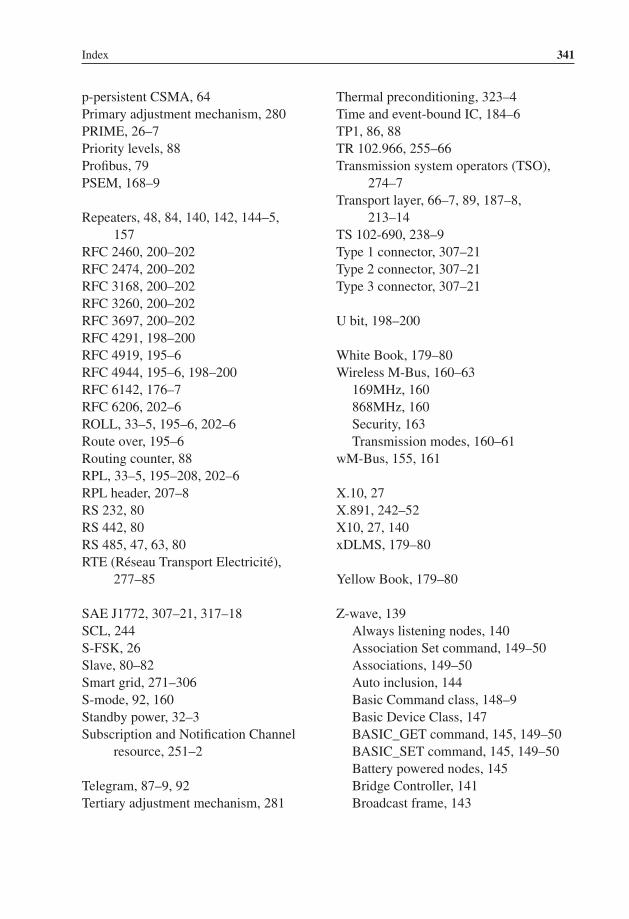
P1: TIX/XYZ P2: ABCJWST118-bind JWST118-Hersent November 29, 2011 9:10 Printer Name: Yet to Come
Index 341
p-persistent CSMA, 64Primary adjustment mechanism, 280PRIME, 26–7Priority levels, 88Profibus, 79PSEM, 168–9
Repeaters, 48, 84, 140, 142, 144–5,157
RFC 2460, 200–202RFC 2474, 200–202RFC 3168, 200–202RFC 3260, 200–202RFC 3697, 200–202RFC 4291, 198–200RFC 4919, 195–6RFC 4944, 195–6, 198–200RFC 6142, 176–7RFC 6206, 202–6ROLL, 33–5, 195–6, 202–6Route over, 195–6Routing counter, 88RPL, 33–5, 195–208, 202–6RPL header, 207–8RS 232, 80RS 442, 80RS 485, 47, 63, 80RTE (Reseau Transport Electricite),
277–85
SAE J1772, 307–21, 317–18SCL, 244S-FSK, 26Slave, 80–82Smart grid, 271–306S-mode, 92, 160Standby power, 32–3Subscription and Notification Channel
resource, 251–2
Telegram, 87–9, 92Tertiary adjustment mechanism, 281
Thermal preconditioning, 323–4Time and event-bound IC, 184–6TP1, 86, 88TR 102.966, 255–66Transmission system operators (TSO),
274–7Transport layer, 66–7, 89, 187–8,
213–14TS 102-690, 238–9Type 1 connector, 307–21Type 2 connector, 307–21Type 3 connector, 307–21
U bit, 198–200
White Book, 179–80Wireless M-Bus, 160–63
169MHz, 160868MHz, 160Security, 163Transmission modes, 160–61
wM-Bus, 155, 161
X.10, 27X.891, 242–52X10, 27, 140xDLMS, 179–80
Yellow Book, 179–80
Z-wave, 139Always listening nodes, 140Association Set command, 149–50Associations, 149–50Auto inclusion, 144Basic Command class, 148–9Basic Device Class, 147BASIC_GET command, 145, 149–50BASIC_SET command, 145, 149–50Battery powered nodes, 145Bridge Controller, 141Broadcast frame, 143

P1: TIX/XYZ P2: ABCJWST118-bind JWST118-Hersent November 29, 2011 9:10 Printer Name: Yet to Come
342 Index
Z-wave (Continued )Collision avoidance, 143Command class, 147–50Command Configuration Set, 150Command record, 150COMMAND_CLASS_
ASSOCIATION, 149–50COMMAND_CLASS_
ASSOCIATION_COMMAND_CONFIGURATION, 150
Commands, 148–9Controllers, 141Device Class, 147Enhanced Slave, 142Explorer frame, 144FLiRS, 142Frame format, 143Frequencies, 142Frequently Listening Routing Slave,
142Generic Device class, 147Get node information command, 148Grouping ID, 149–50Home ID, 141, 146–7Inclusion, 147–8Inclusion Controllers, 141Key Set security encapsulated
command, 151MAC layer, 142–3Multi Instance Association Set
command, 149–50Multi Instance Command
Encapsulation command, 149Multicast frame, 143Multi-instance devices, 149Network wide inclusion, 144NIF, 147, 151Node ID, 141, 146–7Node information frame, 147, 151Output power, 142Portable Controller, 141Power down mode, 140
Primary controller, 141, 146–7Rediscovery procedure, 148Response route, 142Return route, 145RF layer, 142–3Route resolution, 144Routed Singlecast, 145–6Routing layer, 140, 145–8Routing slave, 142Scene Activation command class,
150Scene Actuator Configuration
command class, 150SCENE_ACTIVATION_SET
command, 150Scenes, 150SearchReply, 146SearchRequest, 144–5SearchResult, 144SearchStop, 144, 146Secondary controller, 141, 146–7Security, 150–51Security Command Class, 150Security encapsulated secure command,
151Singlecast frames, 143SIS, 141Slave, 141–2Specific Device class, 147Static Controller, 141Static Update Controller, 141SUC, 141SUC ID Server, 141Transfer layer, 143–5Wake Up Interval Set command, 145Wake Up No More Information, 145Wake Up Notification command, 145Wake-up, 140Wake-Up Beam, 145Wake-Up Command Class, 145ZensorNetTM, 142, 145Z-wave alliance, 139

P1: TIX/XYZ P2: ABCJWST118-bind JWST118-Hersent November 29, 2011 9:10 Printer Name: Yet to Come
Index 343
ZigBee2006/2007, 94, 105Address assignment, 100Adopter status, 93Advanced Ad-Hoc On-Demand
distance Vectoring, 103AODV, 99, 103Application profile, 95, 97, 101,
116–17, 119–29Application support sublayer (APS),
94Application Support Sub-Layer
Management Entity (APSME),95
APS address map, 106APS frame format, 108–9APS layer, 94, 102, 105–9APS security, 114APSME (Application Support
Sub-Layer Management Entity,95
Association Request, 97Association Response, 97–8Attribute, 117Authentication, 115AUX header, 113Beacon, 96–9Beacon Request, 96–9Binding, 69, 94Binding table, 94, 107–8Broadcast, 101–3Broadcast Transaction Table, 101–2,
120BTT, 101–2, 120Child node, 97Cluster, 116Cluster Library, 95, 108, 116–19Command, 117Commisionning ZDP Cluster, 99Coordinator, 96–100Coordinator (ZC), 96CSkip, 100, 105
Demande response and Load controlcluster, 124–6
Developers conference, 93Device Depth, 97Device ID, 106, 117, 119Device Object, 95, 109, 112Device Profile, 95, 106, 108–9, 130Devices, 97–8, 106, 108–10Dimmable light, 121Dimmer Switch, 121End-Device (ZED), 96Endpoint, 106Energy Service Portal (ESP), 123–4EPID, 97ESP (Energy Service Portal), 123–4Extended PAN ID, 97, 99Golden units, 93Groups, 107HA application profile, 119–22Heating / cooling Unit, 122High security mode, 114–15, 123Home Automation, 119–22In premise display service, 124Indirect addressing, 107–8Interop events, 93Key load key, 114Key transport key, 114Keys, 113–14Light Sensor, 121Link keys, 114Load Control Device, 124Logo, 93Low security mode, 114Mains power outlet, 121Manufacturer specific profiles, 108, 119Master keys, 113Messaging Cluster, 129Metering Device, 124Multicast, 101–3Network keys, 114Network layer, 99–105Network management, 110

P1: TIX/XYZ P2: ABCJWST118-bind JWST118-Hersent November 29, 2011 9:10 Printer Name: Yet to Come
344 Index
ZigBee (Continued )Node discovery, 95NWK frame format, 100NWK level security, 112Nwksecuritylevel, 98ON/OFF light, 121PAN ID, 94, 97, 99, 101Participant status, 93PCT (Programmable Communicating
Thermostat), 124Permissions table, 116Permit joining, 98Price cluster, 128–9Pro, 8, 94, 103Profile 0x01, 94, 99–100, 120Profile 0x02, 94, 99–100Programmable Communicating
Thermostat (PCT), 124Promoter status, 93Public application profile, 108, 111,
116–17, 119–22Radius, 101–3Range extender, 121Range Extender Device, 124Route discovery, 103, 107Router (ZR), 96Routing commands, 101–2Security, 111–16Security levels, 112Shade, 121
Shade Controller, 121Short adresses, 99–100Simple descriptor, 106, 116–17Simple metering cluster, 126–8SKKE, 114–15Smart Appliance Device, 124Smart Energy, 123Smart Energy 1.0, 122–9Source routing, 105Stub APS, 122Temperature Sensor, 122Thermostat, 122Tree based routing, 105Trust center, 96, 114–15ZCL (ZigBee Cluster Library), 116–19ZCL frame format, 118ZCL general commands, 118–19ZCP certification, 93sZDO (ZigBee Device Object), 95,
109–11ZDO permissions table, 116ZDP (ZigBee Device Profile), 95,
109–11ZED, 96ZigBee alliance, 93–4, 119ZigBee cluster Library (ZCL), 116–19ZigBee Compliant Platform (ZCP)
certification, 93ZigBee interworking, 258–62ZigBee SEP 2.0, 307–21