the international journal of robotics research
TRANSCRIPT

http://ijr.sagepub.com/Robotics Research
The International Journal of
http://ijr.sagepub.com/content/29/1/23The online version of this article can be found at:
DOI: 10.1177/0278364909103787
2010 29: 23 originally published online 19 May 2009The International Journal of Robotics ResearchEric T. Wolbrecht, David J. Reinkensmeyer and James E. Bobrow
Pneumatic Control of Robots for Rehabilitation
Published by:
http://www.sagepublications.com
On behalf of:
Multimedia Archives
can be found at:The International Journal of Robotics ResearchAdditional services and information for
http://ijr.sagepub.com/cgi/alertsEmail Alerts:
http://ijr.sagepub.com/subscriptionsSubscriptions:
http://www.sagepub.com/journalsReprints.navReprints:
http://www.sagepub.com/journalsPermissions.navPermissions:
http://ijr.sagepub.com/content/29/1/23.refs.htmlCitations:
at UNIV CALIFORNIA IRVINE on August 10, 2011ijr.sagepub.comDownloaded from

Eric T. WolbrechtMechanical Engineering Department,University of Idaho,Moscow, ID 83844,[email protected]
David J. ReinkensmeyerMechanical and Aerospace andBiomedical Engineering Departments,University of California,Irvine, CA 92697,[email protected]
James E. BobrowMechanical and Aerospace Engineering Department,University of California,Irvine, CA 92697,[email protected]
Pneumatic Control ofRobots forRehabilitation
Abstract
Pneumatic actuators are attractive for robotic rehabilitation applica-tions because they are lightweight, powerful, and compliant, but theircontrol has historically been difficult, limiting their use. In this paperwe present the pneumatic control system developed for Pneu-WREX:a pneumatically actuated, upper extremity orthosis for rehabilitationafter stroke. The developed pneumatic control system combines sev-eral novel components to make the entire system stable, reliable, andbackdrivable. These components, which are described in this paper,include: (1) a unique two-valve force control subsystem that keepschamber pressure low (to reduce friction and energy consumption)and adaptively compensates for leakage� (2) a new servovalve char-acterization approach that uses experimentally measured data in acombined non-linear and least-squares regression to obtain a linearrelationship between mass flow and valve voltage� and (3) a new ap-proach to state estimation using accelerometers and a Kalman filterto obtain clean signals for use in a non-linear adaptive feedback con-
The International Journal of Robotics ResearchVol. 29, No. 1, January 2010, pp. 23–38DOI: 10.1177/0278364909103787c� The Author(s), 2010. Reprints and permissions:http://www.sagepub.co.uk/journalsPermissions.navFigures 1, 5, 6, 8–10, 12–15, 17 appear in color online: http://ijr.sagepub.com
trol law. Experimental testing of the device demonstrates the efficacyof the developed pneumatic control system.
KEY WORDS—neurorehabilitation, kalman filter, state es-timation, Lyapunov’s direct method, nonlinear control, forcecontrol, pneumatic control, compliance, movement training,servovalve characterization, radial basis functions, impairmentmodeling
1. Introduction
The goals for a rehabilitation robot are significantly differ-ent to those of a typical industrial robot. A robotic movementtraining device for people recovering after stroke or other neu-rological impairments would ideally be simultaneously strongand compliant, able to assist a subject in completing move-ments while remaining compliant so that the subject can seethe effects of their effort. Therefore, the traditional challengesfor an industrial robotic device, high accuracy, high mechani-cal stiffness, and high bandwidth, are supplanted by the chal-lenges specific to rehabilitation robotics, light weight, highstrength, and low impedance. Although control challengeshave limited their application in the past, pneumatic actuatorscan potentially meet the requirements of rehabilitation robotsbecause they have a high power-to-weight ratio, are mechani-cally compliant because of the inherent compliance of air, and
23
at UNIV CALIFORNIA IRVINE on August 10, 2011ijr.sagepub.comDownloaded from

24 THE INTERNATIONAL JOURNAL OF ROBOTICS RESEARCH / January 2010
Fig. 1. Pneu-WREX: a four degree-of-freedom pneumatically actuated upper extremity orthosis for robotic movement training.The robot controls the position of the hand grip sensor. A forearm cuff provides additional support. The robot can translate freelyalong all three axes, but is constrained to only allow rotation about the z-axis. Specific kinematics are given in Appendix A.
are force controllable. They also have some disadvantages, in-cluding non-linearities in both force and airflow dynamics, andthe requirement of an external source of compressed air.
The control of pneumatic cylinders is well documented inthe literature, with primary methods including feedback lin-earization (Bobrow and McDonell 1998� Xiang and Wikan-der 2004) and sliding mode control (Surgenor and Vaughan1997� Richer and Hurmuzlu 2000a,b� Fite et al. 2006). Thesemethods typically included servovalve airflow modeling, ei-ther from experimental data (Bobrow and McDonell 1998�Leavitt et al. 2006� Wolbrecht et al. 2006) or using nozzleflow equations (Shearer 1956� Richer and Hurmuzlu 2000a,b�Xiang and Wikander 2004). Some of the existing pneumaticmovement training devices, notably the RUPERT upper ex-tremity movement devices (He et al. 2005), use open-loop con-trol. Other pneumatic robotic movement training devices, no-tably the PAM/POGO gait training system (Reinkensmeyer etal. 2006), use a hierarchical control scheme where low-levelforce control uses feedback linearization or sliding mode con-trol and the higher-level, outer-loop control uses conventionalcontrol schemes such as PD control.
A general adaptive, model-based “assist-as-needed’ controlarchitecture developed for Pneu-WREX (Wilmington RoboticExoskeleton (Rahman et al. 2004), see Figure 1) is describedin Wolbrecht et al. (2008) and further details are given in Ap-pendix A. This general control architecture can be applied toany robot (electric or pneumatic) and the steps necessary forits implementation on a low-cost pneumatically actuated robothave not been presented previously. Here we demonstrate thatour control architecture, as applied to Pneu-WREX, achievesgood results appropriate for robotic movement training. Ourapproach requires the development of a novel Kalman filter forstate estimation, inclusion of flow dynamics of air and leakage
estimation in the Lyapunov analysis, servovalve characteriza-tion using experimental data, and an adaptive model of a pa-tient’s abilities and effort. These components are described inthe following sections.
2. Adaptive Position Controller
Pneu-WREX uses a model-based adaptive controller for po-sition control during robotic movement training. The use ofmodel-based control allows the interaction between the deviceand human subject to remain compliant while also providingsufficient force to assist even severely impaired subjects incompleting movements. The adaptive part of the controller al-lows it to learn as the ability of each person who has suffereda stroke varies. This is necessary because the impairment levelvaries widely from subject to subject.
The adaptive position controller includes the “position con-trol subsystem” and “state estimation subsystem” shown inFigure 2. These subsystems, along with the combined ortho-sis and arm dynamics, are described in the following sections.
2.1. Combined Orthosis and Arm Dynamics
The rigid body dynamics of a robotic orthosis when connectedto a human subject are defined in task coordinates as
M �x� �x�C �x� �x� �x�N �x� �x� � Fr � Fh (1)
where x is a n � 1 vector of task space coordinates specify-ing the position and orientation of the hand (for Pneu-WREXn � 4 and x � �
x y z � z�T
), Fr is an n � 1 vector of
at UNIV CALIFORNIA IRVINE on August 10, 2011ijr.sagepub.comDownloaded from

Wolbrecht, Reinkensmeyer, and Bobrow / Pneumatic Control of Robots for Rehabilitation 25
Fig. 2. Top-level controller diagram. A computer game generates desired trajectories for the controller. These trajectories areinterpreted by the human subject visually on the computer screen.
Fig. 3. Adaptive position control subsystem. The adaptive con-troller learns a model of the patients abilities and effort whichallows the compliance of the controller to be high.
forces applied by the robot actuators which is mapped by theJacobian to the interface location, Fh is an n�1 vector of forcesapplied by the human subject at the hand (representing humanmotor output), M is the n � n generalized inertia matrix, C isthe n � n Coriolis matrix, and N is an n � 1 vector of externalforces acting on the robotic orthosis human arm combination,including gravitational, viscous, and spring forces. The forces,Fr , are applied at the location of the subject’s hand using theJacobian transformation developed by Sanchez et al. (2005).The subject is secured to the robot with a hand grip and fore-arm cuff.
2.2. Adaptive Position Controller for Movement Training
The adaptive position control subsystem, shown in Figure 3,determines a desired spatial force, which is the input to theforce control subsystem. The adaptive controller design usesthe sliding surface, s, and reference trajectory, w (Slotine andLi 1991). Here s and w are defined as
s � ��x�����x � ���x� �xd
����� ��x� xd
�w � �xd �����x � �xd ����
��x� xd�
(2)
where �x is the trajectory tracking error, �x and xd are n � 1vectors of the estimated and desired location of the hand, re-
spectively, and ��� is an n � n symmetric, constant, positive-definite, gain matrix. The control law for this method specifiesthe desired spatial robot force, Fd
r , as
Fdr � Y �x� �x�w� �w��a�KP�x�KD
��x (3)
where KP and KD are symmetric, constant, positive-definitegain matrices and Y�a is a model of the system dynamicsincluding the forces generated by the human subject and isdefined as
Y�a � �M �w� �Cw� �N� Fh (4)
where �M, �C, and �N are estimates of the dynamics of the roboticorthosis and human arm combination, Y is a m � n matrix ofknown functions of �x, �x, w, and �w, and �a is an m � 1 vector ofparameter estimates.
In order for Pneu-WREX to interact compliantly with eachsubject, the feedback gains KP and KD are kept small. In prac-tice, the effective stiffness of the robot was 109 N m�1 (Wol-brecht et al. 2008). To gain an approximate feel for how com-pliant this made the robot, consider a scenario in which theperson relaxes the arm (approximately 40 N) and the robotlifts the arm to a target. If the person now applies a suddenforce equal to the weight of his arm, the robot will displace byapproximately 37 cm.
The dynamic model, Y�a, should have sufficient resolutionand complexity to appropriately adapt to the diverse impair-ment characteristics typically seen in people who have suffereda stroke or other neurological injury. The dynamic model usedfor Pneu-WREX uses radial basis functions to model patientoutput force capability as defined in Appendix A and Wol-brecht et al. (2008).
The basis function parameter estimates, �a, are updated ac-cording to ��a � �����1YTs (5)
which is required for stability from the Lyapunov analysis pro-vided in Appendix C. We note that the stability analysis in-cludes the compressible flow and non-linearities of the pneu-matic cylinders.
In the force control law given in (3), Y�a is an estimate of theforces required by the robotic orthosis to move the human ex-tremity along the desired reference trajectory, w. This model
at UNIV CALIFORNIA IRVINE on August 10, 2011ijr.sagepub.comDownloaded from

26 THE INTERNATIONAL JOURNAL OF ROBOTICS RESEARCH / January 2010
Fig. 4. State estimation subsystem. State estimation is used toobtain smooth position, velocity, and acceleration signals.
varies depending on the dynamics of the patient’s extremity,the patient’s neurological ability, and the patient’s effort. HereY�a is a feedforward term in the control law, allowing the con-troller to move a patient’s extremity along a desired trajectorywhile keeping the proportional, KP , and derivative gains, KD ,small, so that the resulting controlled environment feels com-pliant to the patient.
2.3. State Estimation
In order to improve the position and velocity signals usedfor the control of Pneu-WREX, two two-axis microelectro-mechanical system (MEMS) accelerometers (Analog DevicesADXL320EB) were installed on the end-effector of the ortho-sis. Using the accelerometer measurements and the forwardkinematics of the position sensors, a Kalman filter was de-signed to estimate the position and velocity of the end-effectorin task space, as shown in Figure 4. Using the forward kine-matics defined in Appendix B and the spatial Jacobians devel-oped by Sanchez et al. (2005), the end-effector velocities aremapped back to both joint and cylinder velocities.
With the accelerometers properly oriented the task spaceaccelerations of the end-effector, �x � � �x �y �z �� z
�, can be
measured. Combined with the forward kinematics, the statespace equations for the measurement system are (shown belowfor the x direction)
����x�x
� � �
�
0 0 0
0 0 1
�� 0 0
� �
��
x
�x
� ��
�
0
0
�
� � �xm
�
�
1 0
0 0
0 ��
� �� b
a
��
xm ��
0 1 0���
x
�x
� �� e (6)
where � and � are the accelerometer offset and scaling con-stants, �xm is the voltage measurement from the accelerometer,xm is the position measurement calculated from the forwardkinematics of the joint angles as measured by the potentiome-ters, and b, a , and e are assumed to be Gaussian white mea-surement noise. The system in (6) has the form
�r � Ar� Bam � Ba
xm � Cr� e (7)
where r ��� x �x
�T, and A, B, B , and C are defined
from (6). A state estimator for this system is defined as
��r � A�r�K�xm �C�r�� Bam (8)
where K is the estimator gain matrix and �r is the state estima-tion. The error of the state estimator is
e � r� �r (9)
Substituting (7) and (8) into (9) gives (in the absence of noise),
�e � �A�KC� e (10)
We see from (10) that if K is selected so that the eigenval-ues of A � KC have negative real parts, then e �t� � 0 ast � . The estimator gain matrix Ke was determined bysolving the linear quadratic regulator problem for the system�q � A �q � Bu, where A � AT and B � CT. The valuesfor the state weighting matrix Q and the control matrix R weretuned experimentally to balance the state estimation responsetime to its susceptibility to noise. MATLAB’s lqr commandwas used to find the estimator gain matrix Ke for each tun-ing iteration. Good performance was found using the estimator
gain matrix Ke ���316 101 5050
�T
A similar estima-
tor is used for the other task space coordinates ( �y, �z, and �� z).
3. Pneumatic Force Controller
The pneumatic force controller takes the desired task-spaceforce from (3) and determines the flow rates required from theservovalves to produce this force. These flow rates are thenconverted into a spool voltage using a flow map that was de-termined using experimental data. The following sections firstdescribe the equations for the output force from a pneumaticcylinder and how to choose smooth individual chamber forces(Section 3.1). Next, the details of the cylinder chamber forcedynamics are given in Section 3.2. In Section 3.3, the forcecontroller with adaptive leakage compensation is presented.Section 3.4 describes the servovalve characterization.
at UNIV CALIFORNIA IRVINE on August 10, 2011ijr.sagepub.comDownloaded from

Wolbrecht, Reinkensmeyer, and Bobrow / Pneumatic Control of Robots for Rehabilitation 27
Fig. 5. Desired individual chamber force selection subsystem.Individual chamber forces are selected to produce a desired netoutput force. A smoothing term keeps the desired individualchamber forces smooth in their first derivatives as the desirednet output force crosses zero.
3.1. Cylinder Chamber Forces
In order to define the flow control laws for the servovalves,we first need to determine the desired forces at the cylinderlevel, as shown in Figure 5. Starting with the forward kine-matic home positions given in Appendix B, the spatial Jaco-bian transformations for end-effector forces, Je, and the cylin-der forces, Jc, developed by Sanchez et al. (2005) are used todefine the relationship between the desired task forces from thecontroller at the human/orthosis interface, Fd
r , and the desiredcylinder forces, fd , according to
fd � J�Tc JT
e Fdr (11)
The desired cylinder forces, fd , are used to determine the de-sired individual chamber forces, fd
A and fdB . To select the indi-
vidual chamber forces, we define the net output force from thenth double acting pneumatic cylinder as
fn � fn�A � fn�B � fatm (12)
where fn is the net output force, fn�A is the force on pistonfrom the non-rod side cylinder chamber, fn�B is the force onpiston from the rod side cylinder chamber, and fatm is the forceon the piston from atmospheric pressure on the exposed rod.
Pneu-WREX uses a servovalve for each cylinder chamber,allowing both fn�A and fn�B to be controlled independently.This configuration, although more expensive in terms of ad-ditional valves and electronics, is important in that it allowsindividual chamber pressures to be kept low, which reducesthe actuation stiffness and the effects of seal friction. This al-lows the robot to be highly compliant and backdrivable, whichare both desirable for robots for rehabilitation.
To keep the desired chamber forces continuous in their firstderivatives the desired chamber forces, f d
n�A and f dn�B , are set
such that the desired net output force is f dn � f d
n�A � f dn�B �
fatm , and that
f dn�A � 1
2�e����� f d
n
��� � f0 � fatm �max�
f dn � 0
�
f dn�B � 1
2�e����� f d
n
��� � f0 �min�� f d
n � 0�
(13)
where f0 is the minimum chamber force, and � is a smooth-ing constant. The minimum chamber force is chosen to beslightly greater than the force of atmospheric pressure on thepiston head, which is the lowest possible force produced bythe air in the cylinder chamber. The exponential term in (13)smoothes the desired chamber forces as the desired net outputforce crosses zero. This keeps fn�A and fn�B continuous in theirfirst derivatives, which is necessary for the stability analysis.We note that most other pneumatic control researchers com-pletely ignore this discontinuity and, as our experimental re-sults show, doing so causes a noticeable force error or distur-bance to act on the system.
As the ideal rehabilitation system is completely backdriv-able, it is undesirable to have these force errors when the over-all output force levels are low. Selecting � represents a tradeoff�a smaller � makes the exponential term in f d
n�A and f dn�B decay
slowly, but increases the average cylinder chamber force whenthe desired net output force is zero. Setting the desired cylin-der chamber forces according to (13) keeps the average cylin-der chamber pressure low if f0 is low, thereby reducing energyconsumption (Al-Dakkan et al. 2003�Granosik and Borenstein2004) and seal friction, which improves backdrivability in zeroforce control mode.
3.2. Cylinder Chamber Force Dynamics
The dynamics of the force produced by air in a cylinderchamber are well documented in the literature (Bobrow andMcDonell 1998� Richer and Hurmuzlu 2000a,b� Xiang andWikander 2004). The dynamics of force for the non-rod sidechambers of n cylinders can be approximated by
�fA � V�1A k
�RT AA � �mA � lA�� �VAfA
�(14)
where fA is a n � 1 vector of non-rod side cylinder chamberforces, k is the ratio of specific heats of air, R is the universalgas constant, T is the air temperature, �mA is a n � 1 vector ofmass flow rates into the non-rod side cylinder chamber due tospool valve position, lA is a n � 1 vector of mass flow ratesinto the non-rod side cylinder chamber due to leakage, and AA
and VA are n � n diagonal matrices defined as
AA �
�
aA�1 0
aA�2
0 aA�n
� ��
at UNIV CALIFORNIA IRVINE on August 10, 2011ijr.sagepub.comDownloaded from
28 THE INTERNATIONAL JOURNAL OF ROBOTICS RESEARCH / January 2010
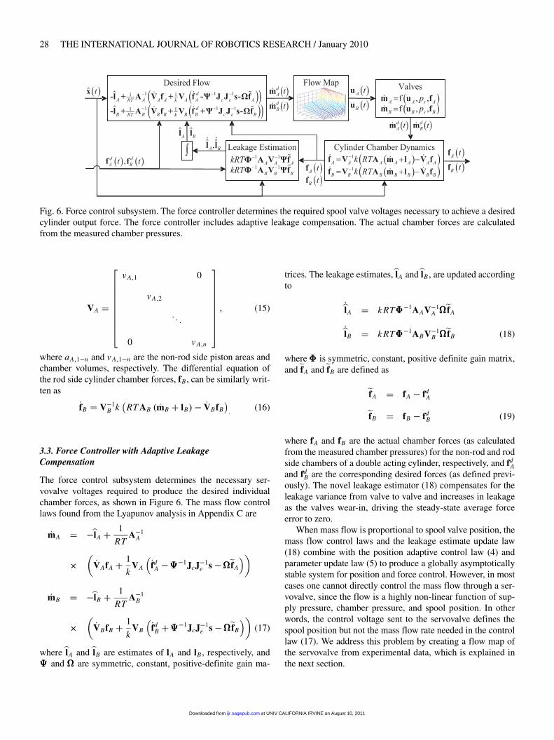
Fig. 6. Force control subsystem. The force controller determines the required spool valve voltages necessary to achieve a desiredcylinder output force. The force controller includes adaptive leakage compensation. The actual chamber forces are calculatedfrom the measured chamber pressures.
VA �
�
A�1 0
A�2
0 A�n
� �� (15)
where aA�1�n and A�1�n are the non-rod side piston areas andchamber volumes, respectively. The differential equation ofthe rod side cylinder chamber forces, fB , can be similarly writ-ten as
�fB � V�1B k
�RT AB � �mB � lB�� �VBfB
�
(16)
3.3. Force Controller with Adaptive LeakageCompensation
The force control subsystem determines the necessary ser-vovalve voltages required to produce the desired individualchamber forces, as shown in Figure 6. The mass flow controllaws found from the Lyapunov analysis in Appendix C are
�mA � ��lA � 1
RTA�1
A
���VAfA � 1
kVA
��fdA �����1JcJ�1
e s�����fA
��
�mB � ��lB � 1
RTA�1
B
���VBfB � 1
kVB
��fdB �����1JcJ�1
e s�����fB
��(17)
where �lA and �lB are estimates of lA and lB , respectively, and��� and ��� are symmetric, constant, positive-definite gain ma-
trices. The leakage estimates,�lA and�lB , are updated accordingto
��lA � k RT �1AAV�1A ���
�fA
��lB � k RT �1ABV�1B ���
�fB (18)
where is symmetric, constant, positive definite gain matrix,and�fA and�fB are defined as
�fA � fA � fdA
�fB � fB � fdB (19)
where fA and fB are the actual chamber forces (as calculatedfrom the measured chamber pressures) for the non-rod and rodside chambers of a double acting cylinder, respectively, and fd
Aand fd
B are the corresponding desired forces (as defined previ-ously). The novel leakage estimator (18) compensates for theleakage variance from valve to valve and increases in leakageas the valves wear-in, driving the steady-state average forceerror to zero.
When mass flow is proportional to spool valve position, themass flow control laws and the leakage estimate update law(18) combine with the position adaptive control law (4) andparameter update law (5) to produce a globally asymptoticallystable system for position and force control. However, in mostcases one cannot directly control the mass flow through a ser-vovalve, since the flow is a highly non-linear function of sup-ply pressure, chamber pressure, and spool position. In otherwords, the control voltage sent to the servovalve defines thespool position but not the mass flow rate needed in the controllaw (17). We address this problem by creating a flow map ofthe servovalve from experimental data, which is explained inthe next section.
at UNIV CALIFORNIA IRVINE on August 10, 2011ijr.sagepub.comDownloaded from

Wolbrecht, Reinkensmeyer, and Bobrow / Pneumatic Control of Robots for Rehabilitation 29
Fig. 7. Experimental setup for flow measurements.
3.4. Servovalve Characterization
The mass flow rate, �m, through a servovalve is in general afunction of valve spool position u, supply pressure ps , and thechamber pressure, pc. Past work has modeled the mass flowof air through a servovalve as mass flow through a variableorifice (Sanville 1971) or a nozzle. This approach has beencombined with dead band compensation (Xiang and Wikander2004). Others have added detailed effective flow area calcu-lations (Richer and Hurmuzlu 2000a,b). These methods typi-cally define separate equations for choked and unchoked flow,based on a critical pressure. These theoretical flow equationshave been shown to be only approximations of actual massflow through a servovalve (Bobrow and McDonell 1998). Inaddition, it is difficult, at best, to combine theoretical flowequations with the variable orifice effects of the spool valvedead band. For these reasons, the control of Pneu-WREX, themass flow relationship for the Festo servovalve (model MPYE-5-1/8-LF-010-B), was determined experimentally.
Flow experiments have been performed in the past byBobrow and McDonell (1998) and Granosik and Borenstein(2004) and others. For our experiments, two servovalves wereset up in series with a chamber in the middle (see Figure 7).
Air was supplied to the first servovalve at 690 kPa andexhaust flow was measured on the second servovalve us-ing a Honeywell AWM720P1 mass air flow sensor. Thisconfiguration is necessary because the mass flow sensor hasa maximum pressure rating significantly lower than the sup-ply pressure. The control voltage, u, for each valve was variedindependently, creating different chamber pressure and flowcombinations. This process was automated, which greatly re-duced data collection time. Chamber pressure, pc, and mass airflow, �m, were measured for each steady-state flow condition.Owing to conservation of mass, the mass air flow data col-lected characterizes both flow into a chamber (through the firstvalve) and flow out of a chamber (through the second valve).Figure 8 shows data collected from the first servovalve, rep-resenting flow into the chamber from one of the experiments.To simplify the equation fitting, the valve offset voltage (5 V)
Fig. 8. Measured mass air flow into the chamber. To simplifythe equation fitting, the valve offset voltage (5 volts) was sub-tracted from the measured data.
was subtracted from the measured data (the Festo valve oper-ates from 0 to 10 V with zero flow at 5 V).
Attempts to fit the inflow data to the previously mentionedanalytical functions resulted in a poor fit. Different functionswere experimented with in order to find surfaces that betterapproximated the data. The best fitting function we found forinflow is
u � c1�m2�
1� p28c
�q1� c2
�m1�5�1� p28
c
�q2� c3 �m1�5 (20)
where u is the servovalve spool voltage, �m is the required massflow, pc is the chamber pressure, and c1�3 and q1�2 are thefitting constants.
To determine the constants in (20)
J � �A �q�C� B�2 (21)
was used as the cost function, where C � [c1 c2 c3]T andA �q� and B have rows corresponding to each measured datapoint, with each row defined as
Ai ���m2
i ��1� p28
c�i
�q1 �m1�5i �
�1� p28
c�i
�q2 �m1�5i
��
Bi � [ui ] (22)
The cost function was minimized in an iterative two-stepprocess. For the first step the q were held constant and thebackslash operator in Matlab was used to perform multiplelinear regression to find the c. In the second step the Matlabfunction fminunc was used for a non-linear minimization ofthe q while holding the c at the values determined from theprevious step. These two steps were repeated until the q andthe c converged. The converged values for the Festo valve are
at UNIV CALIFORNIA IRVINE on August 10, 2011ijr.sagepub.comDownloaded from
30 THE INTERNATIONAL JOURNAL OF ROBOTICS RESEARCH / January 2010
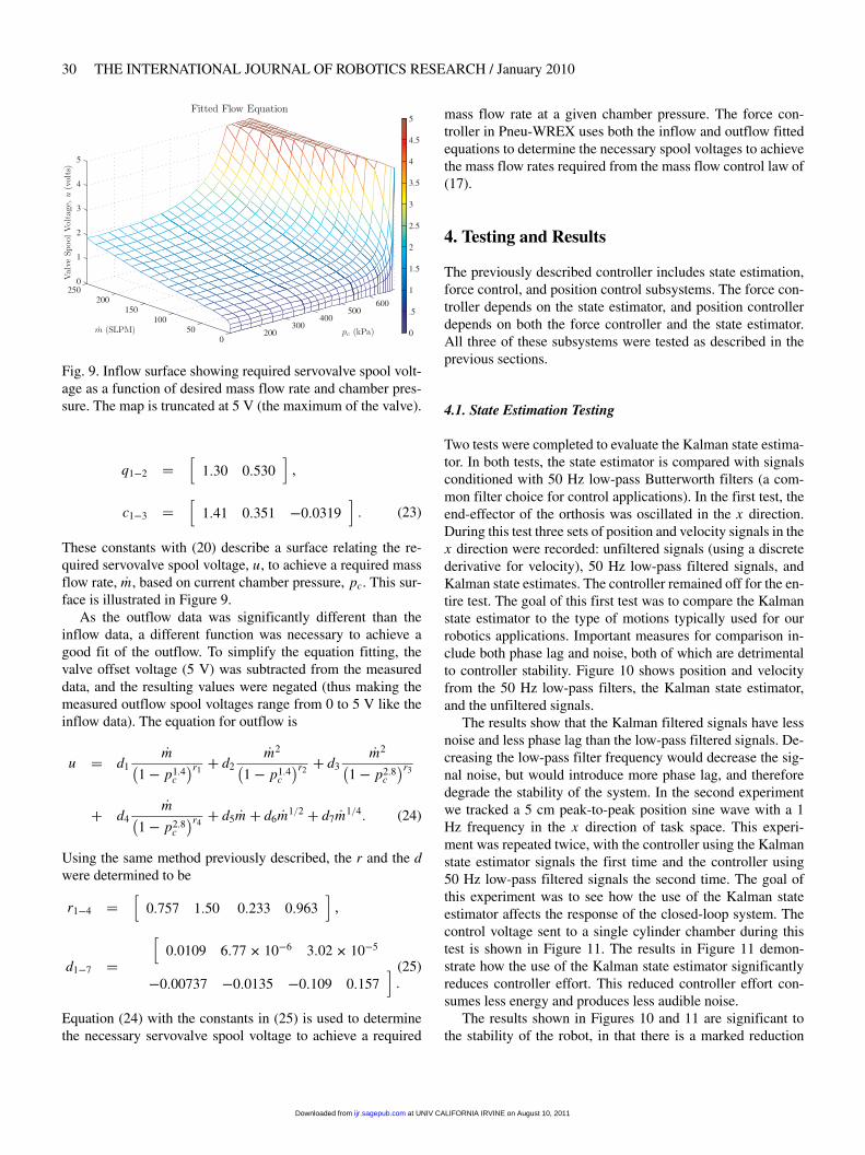
Fig. 9. Inflow surface showing required servovalve spool volt-age as a function of desired mass flow rate and chamber pres-sure. The map is truncated at 5 V (the maximum of the valve).
q1�2 ��
130 0530��
c1�3 ��
141 0351 �00319� (23)
These constants with (20) describe a surface relating the re-quired servovalve spool voltage, u, to achieve a required massflow rate, �m, based on current chamber pressure, pc. This sur-face is illustrated in Figure 9.
As the outflow data was significantly different than theinflow data, a different function was necessary to achieve agood fit of the outflow. To simplify the equation fitting, thevalve offset voltage (5 V) was subtracted from the measureddata, and the resulting values were negated (thus making themeasured outflow spool voltages range from 0 to 5 V like theinflow data). The equation for outflow is
u � d1�m�
1� p14c
�r1� d2
�m2�1� p14
c
�r2� d3
�m2�1� p28
c
�r3
� d4�m�
1� p28c
�r4� d5 �m � d6 �m1�2 � d7 �m1�4 (24)
Using the same method previously described, the r and the dwere determined to be
r1�4 ��
0757 150 0233 0963��
d1�7 ��
00109 677� 10�6 302� 10�5
�000737 �00135 �0109 0157�(25)
Equation (24) with the constants in (25) is used to determinethe necessary servovalve spool voltage to achieve a required
mass flow rate at a given chamber pressure. The force con-troller in Pneu-WREX uses both the inflow and outflow fittedequations to determine the necessary spool voltages to achievethe mass flow rates required from the mass flow control law of(17).
4. Testing and Results
The previously described controller includes state estimation,force control, and position control subsystems. The force con-troller depends on the state estimator, and position controllerdepends on both the force controller and the state estimator.All three of these subsystems were tested as described in theprevious sections.
4.1. State Estimation Testing
Two tests were completed to evaluate the Kalman state estima-tor. In both tests, the state estimator is compared with signalsconditioned with 50 Hz low-pass Butterworth filters (a com-mon filter choice for control applications). In the first test, theend-effector of the orthosis was oscillated in the x direction.During this test three sets of position and velocity signals in thex direction were recorded: unfiltered signals (using a discretederivative for velocity), 50 Hz low-pass filtered signals, andKalman state estimates. The controller remained off for the en-tire test. The goal of this first test was to compare the Kalmanstate estimator to the type of motions typically used for ourrobotics applications. Important measures for comparison in-clude both phase lag and noise, both of which are detrimentalto controller stability. Figure 10 shows position and velocityfrom the 50 Hz low-pass filters, the Kalman state estimator,and the unfiltered signals.
The results show that the Kalman filtered signals have lessnoise and less phase lag than the low-pass filtered signals. De-creasing the low-pass filter frequency would decrease the sig-nal noise, but would introduce more phase lag, and thereforedegrade the stability of the system. In the second experimentwe tracked a 5 cm peak-to-peak position sine wave with a 1Hz frequency in the x direction of task space. This experi-ment was repeated twice, with the controller using the Kalmanstate estimator signals the first time and the controller using50 Hz low-pass filtered signals the second time. The goal ofthis experiment was to see how the use of the Kalman stateestimator affects the response of the closed-loop system. Thecontrol voltage sent to a single cylinder chamber during thistest is shown in Figure 11. The results in Figure 11 demon-strate how the use of the Kalman state estimator significantlyreduces controller effort. This reduced controller effort con-sumes less energy and produces less audible noise.
The results shown in Figures 10 and 11 are significant tothe stability of the robot, in that there is a marked reduction
at UNIV CALIFORNIA IRVINE on August 10, 2011ijr.sagepub.comDownloaded from

Wolbrecht, Reinkensmeyer, and Bobrow / Pneumatic Control of Robots for Rehabilitation 31
Fig. 10. Filtering comparison for position and velocity signals. The end-effector was oscillated in the x direction. The top left plotshows the position of the end-effector, with a magnified view of this plot shown in the top right plot (as indicated by the box andarrow). The bottom left plot shows the velocity of the end-effector in the x direction, with a magnified view of this plot shown inthe bottom right plot (as indicated by the box and arrow). Unfiltered, low-pass filtered (50 Hz Butterworth), and Kalman filteredsignals are shown in all four plots. Note how the Kalman filtered signals have less noise and less phase lag than the low-passfiltered signals.
Fig. 11. Controller effort using Kalman state estimation versus using 50 Hz low-pass filtered signals. The controller using theKalman state estimator (right-hand side plot) is significantly smoother, producing less audible noise and consuming less pneu-matic and electrical energy.
is signal noise and phase lag, which reduces the controllablebandwidth of the system, as well as a reduction in controllereffort and control signal frequency, which can excite the nat-ural mechanical and pneumatic frequency of the robot, furtherreducing system stability.
4.2. Force Controller Testing
Two tests were performed to evaluate force controller perfor-mance. In the first test we compared the force controller withand without the smoothing term in (13). For the experimentswithout the smoothing term, we simply omitted the exponen-
at UNIV CALIFORNIA IRVINE on August 10, 2011ijr.sagepub.comDownloaded from

32 THE INTERNATIONAL JOURNAL OF ROBOTICS RESEARCH / January 2010
Fig. 12. Force tracking results with (right column) and without (left column) the inclusion of a smoothing term. The desired andactual total forces are shown on the bottom half of each row and the desired and actual chamber forces are shown in the top halfof each row. The desired total force is a peak-to-peak 50 N sine wave at 1 Hz (top row), 2 Hz (middle row), and 4 Hz (bottomrow).
tial term so that the desired non-rod side chamber force, f dn�A,
and the rod side chamber force, f dn�B are set according to
f dn�A � f0 � fatm �max
�f dn � 0
�f dn�B � f0 �min
�� f dn � 0
�(26)
for a given desired total cylinder force, f dn . As low friction
cylinders are used, and individual chamber pressures are keptlow, the forces from seal friction are small and have been as-sumed to be zero. For both experiments (with and without asmoothing term), the desired total force was a 50 N peak-to-peak sine wave. The cylinder used in these experiments hada 5.08 cm bore and 7.62 cm stroke. For this experiment, therod end of the cylinder was held in a fixed position. At differ-ent piston positions the nonlinear controller accounts for thechange in chamber air volume. However, the change in vol-ume changes the length of the air column in the controlled
chamber, and thus will moderately affect the force controllerperformance. The volumes of the non-rod side and rod sidechambers during these experiments were 157 and 182 cm3, re-spectively. The results for 1, 2, and 4 Hz tracking are shown inFigure 12.
The results shown in Figure 12 demonstrate how thesmoothing term in (13) improves force control by keepingthe transition from positive to negative desired force (and viceversa) continuous in the first derivative.
In the second test of the force controller we evaluated thefrequency response by tracking a 50 N peak-to-peak sine wavein a single cylinder at multiple frequencies. As in the previousforce tracking experiment, the cylinder had a 5.08 cm bore and7.62 cm stroke. In addition, the rod of the cylinder was heldfixed, with the non-rod side and rod side chambers having 157and 182 cm3 volumes, respectively. Force tracking results at1, 2, 4, 10, 20, and 40 Hz are shown in Figure 13. The results
at UNIV CALIFORNIA IRVINE on August 10, 2011ijr.sagepub.comDownloaded from

Wolbrecht, Reinkensmeyer, and Bobrow / Pneumatic Control of Robots for Rehabilitation 33
Fig. 13. Force tracking for a single cylinder at multiple frequencies. The desired force is a 50 N peak-to-peak sine wave. Resultsfor 1, 2, 4, 10, 20, and 40 Hz are shown in the top left, top right, middle left, middle right, bottom left, and bottom right plots,respectively.
show good tracking at frequencies up to 20 Hz or higher for asingle cylinder chamber.
The results from both force tracking experiments, shown inboth Figure 12 and Figure 13 are from one cylinder in the com-pleted Pneu-WREX orthosis. Owing to the mechanical designand plumbing layout, the distances between the servovalvesand the cylinders is significantly larger than those typicallypresented in the pneumatic control literature. Improved overallforce tracking performance and a higher frequency responseshould be possible by shortening the distance between the ser-vovalves and the pneumatic cylinders.
4.3. Position Controller Testing
Two separate tests were performed to evaluate the positiontracking of the adaptive controller. In the first test, the orthosistracked a 5 cm peak-to-peak sine wave in the x direction (leftto right with respect to the orientation of a subject in the ortho-sis) at multiple frequencies. The goal of this test was to evalu-ate small amplitude tracking for multiple frequencies. The re-sults for tracking 0.5, 1, and 2 Hz sine waves are shown inFigure 14.
The results show good tracking position tracking for up to 2Hz after the adaptation parameters had reached a steady state.By reducing the amplitude of the sine wave, slightly higherfrequencies can be maintained. Such higher frequencies, how-ever, are not typically used for rehabilitative movement train-ing.
In the second position tracking test, the orthosis tracked aminimum jerk trajectory in task space at a speed typical formovement training. The goal of this test was to evaluate track-ing for a typical training movement, and to verify the perfor-mance both with and without a human subject’s arm connectto the device. In the test a repeated minimum jerk trajectorywas tracked from –20 to 20 and then back to 20 cm in the xdirection of task space (left to right with respect to the orienta-tion of the subject). The desired trajectory had a peak velocityof 14.8 cm s�1, which is within the range of normal movementtraining. This test was repeated for both with (bottom row) andwithout (top row) a subject’s arm in the orthosis, as shown inFigure 15. The subject relaxed his arm when it was in the or-thosis.
The results from the test demonstrate the ability of the con-troller to achieve good tracking for both unloaded (orthosisonly) and loaded (orthosis with a subject’s arm attached) con-ditions.
5. Discussion and Conclusions
The ideal robotic device for movement training after strokeshould be strong, lightweight, and compliant, making the useof traditional actuators, such as electric motors, problematic.Pneumatic actuators have a high strength-to-weight ratio andare inherently compliant, making them good candidates for ro-botic movement training devices.
at UNIV CALIFORNIA IRVINE on August 10, 2011ijr.sagepub.comDownloaded from

34 THE INTERNATIONAL JOURNAL OF ROBOTICS RESEARCH / January 2010
Fig. 14. Adaptive controller position tracking results. The robotic orthosis tracked a 5 cm peak-to-peak sine wave in the xdirection (left to right) of task space for a period of 90 seconds. The left column shows the first 10 seconds, where the desiredsine wave was gradually introduced and most of the parameter adaptation took place. The right column shows the last 2 secondsof tracking where the parameters had reached steady state. The first, second, and third rows show desired tracking frequencies of0.5, 1, and 2 Hz, respectively.
Fig. 15. Minimum jerk trajectory tracking results for a large movement. The robotic orthosis tracked a minimum jerk trajectoryfrom left (–20) to right (20) with a peak velocity of 14.8 cm s�1 and a frequency of 0.1 Hz. The left column shows the first 20seconds of tracking and the right column shows seconds 70–90. The top row results are for the orthosis only, the bottom row forthe orthosis with a subject’s arm connected. In both cases, the controller adaptation produces good tracking in the steady state.
In this paper we have presented an adaptive controller fora pneumatically actuated orthosis that exhibits good controlfor robotic movement training with human subjects. The con-
troller includes adaptation for both the inner (force control)and outer (position control) layers of the controller. We devel-oped several techniques to improve the performance of pneu-
at UNIV CALIFORNIA IRVINE on August 10, 2011ijr.sagepub.comDownloaded from

Wolbrecht, Reinkensmeyer, and Bobrow / Pneumatic Control of Robots for Rehabilitation 35
matic systems, including the use of a Kalman filter for stateestimation which decreases control effort, valve chatter, andthe audible noise of the system.
The results presented in this paper show that the adap-tive controller implemented for the pneumatic orthosis, namedPneu-WREX, achieves cylinder chamber force control in ex-cess of 20 Hz and small amplitude position tracking in taskspace up to 2 Hz. Additional results show how the adaptivecontroller achieves good tracking for a typically large mini-mum jerk trajectory training movement both with and withouta subject’s arm connected to the device.
The robotic movement training device is lightweight,strong, compliant, and assists when the subject is unable to byforming a model of the patients’ abilities. The resulting com-pliant environment gives the human subject a sense of controlover the movement training.
Acknowledgement
This work was supported in part by NIH N01-HD-3-3352 andNCRR M01RR00827.
Appendix A: Impairment Modeling with RadialBasis functions
In the current implementation of Pneu-WREX (see also Wol-brecht et al. (2008)), the regressor matrix Y�a comprises spa-tially dependent Gaussian radial basis functions, defined as
gn � exp����x� �n
��2�2� 2
�(27)
where gn is the nth radial basis function, x is the current loca-tion of the patient’s hand, �n is the location of the nth radialbasis function, and � is effectively a scalar smoothing con-stant that determines the width of the basis function. For Pneu-WREX we have implemented a three-dimensional grid of ra-dial basis functions, with eight grid divisions left to right (�xto �x), five grid divisions in and out (�y to �y), and threegrid divisions down to up (�z to �z) across the workspace ofthe robot, and with � � 762 cm. The grid divisions are evenlyspaced at 10 cm apart. The value of � changes the width ofeach radial basis function so it must be determined in conjunc-tion with the grid spacing, so that there is sufficient overlap inthe radial basis functions to achieve good function approxima-tion. The grid spacing was chosen to be small enough to obtainreasonable spatial variance in the function approximation butwithout adding excessive computational expense for real-timecontrol. The vector of all of the Gaussian radial basis functionsis defined as
g ��
g1 g2 g120
�T (28)
We combine this vector of Gaussian radial basis functions todefine the regressor matrix Y as
Y3x360 �
�
gT 0 0
0 gT 0
0 0 gT
� � (29)
The parameter estimate vector, �a, is therefore a 360 � 1 vec-tor, with the parameters representing the amount of force thesubject is unable to provide to hold their arm at a particularlocation in space. Including more parameters (e.g. more ba-sis functions) is possible and would allow the model to rep-resent more complicated impairment, but would also increasethe computational expense. When all of the inertial and gravi-tational terms of (4) are included, and the force output fromthe human subject remains time independent, the controllerdefined by (3) and (5) is globally asymptotically stable. For theimplementation with Pneu-WREX used here, however, the in-ertial components of the dynamic model were omitted becausethe movements of interest were relatively slow and doing so re-sulted in a significant reduction in the real-time computationalload.
Appendix B: Pneu-WREX Kinematics
The forward kinematics for Pneu-WREX follow the methodfirst developed by Sanchez et al. (2005). In addition, the serialchain is simplified, removing the need for q3b and q4b. Therevised home position coordinates necessary for the forwardkinematic analysis methods of Murray et al. (1994) are (theorigin of these points is at the center of the patient’s impairedshoulder)�
q1�q2� q3� q4�q5� q5b�
�
�
0 �391�391 �391 009 �0016
0 0 14 14� ua 295� ua 125� ua
0 0 � � 3 � � 3 � � 6375 � � 6375
� �
�qc1b� qc2b�qc3b�qc4b
�
�
��2125 �5351 �6474 �6574
�129 �2075 14 �68
0 0 � � 15 � � 82
� �
at UNIV CALIFORNIA IRVINE on August 10, 2011ijr.sagepub.comDownloaded from

36 THE INTERNATIONAL JOURNAL OF ROBOTICS RESEARCH / January 2010
Fig. 16. Upper arm length, ua, and shoulder height, ,definitions.
�qc1r �qc2r �qc3r � qc4r
�
�
��215 �5377 �6474 �629
0 1467 12051 3454� ua
0 0 � � 3 � � 7692
� �
qarm � q5 � hand (30)
where variables ua and define the length of the upper arm,and the distance between the upper-shoulder joint and theshoulder in inches, respectively (see Figure 16).
In addition in (30) above, qi are points on the joint axes,qcib are points on the cylinder base axes, qcir are points onthe cylinder rod axes, qarm is the location of the interface be-tween Pneu-WREX and the subject’s forearm, and hand ��armx army armz
�Tis the location of the hand with re-
spect to the last axis, q5. The locations of these points are de-picted in Figure 17.
Pneu-WREX has six rotation axes. The angles about therotation axes are defined as
� f ull ���1 �2 �3 �4 �5 �5b
�T(31)
where � f ull is the full 6 � 1 vector of all joint axes on Pneu-WREX. The axes of rotation are defined as�
�1 �2 �3 �4 �5 �5b
�
�
�
0 0 1 1 0 0
0 0 0 0 0 0
1 1 0 0 1 1
� � (32)
where �i are unit vectors along each axis of rotation. The lo-cation of these rotation axes are shown in Figure 17.
Fig. 17. Pneu-WREX home positions for kinematic equations.
Appendix C: Lyapunov Stability Analysis
For the stability analysis of the adaptive position control ap-plied to a pneumatic system, we consider the Lyapunov func-tion candidate:
V �t� � 1
2sTMs� 1
2�xT �KP ����KD��x� 1
2�aT����a
� 1
2�fT
A����fA � 1
2�fT
B����fB � 1
2�lTA �lA � 1
2�lTB �lB (33)
where s, M, �x, KP , KD ,��� , ���,���, ,�fA, and�fB are as definedpreviously, �a,�lA, and�lB , are parameter estimate errors definedas
�a � �a� a
�lA � �lA � lA
�lB � �lB � lB (34)
where �a, �lA, and �lB are parameter estimates as defined previ-ously, and a, lA, and lB are the actual parameter values. Takingthe derivative of (33) along system trajectories gives
�V �t� � 1
2sT �Ms� sTM�s� �xT �KP ����KD� ��x� �aT��� ��a
� �fTA�����fA ��fT
B�����fB ��lTA ��lA ��lT
B ��lB (35)
Using the sliding surface, s, and reference trajectories, w,defined in (2), the system dynamics in (1) can be redefinedas
M�s� Cs� Ya � Fr (36)
at UNIV CALIFORNIA IRVINE on August 10, 2011ijr.sagepub.comDownloaded from

Wolbrecht, Reinkensmeyer, and Bobrow / Pneumatic Control of Robots for Rehabilitation 37
Next, substituting for M�s from (36) into (35), and using thefact that �M� 2C is skew-symmetric, gives
�V �t� � sT �Fr �Ya�� �xT �KP ����KD� ��x� �aT��� ��a� �fT
A�����fA ��fT
B�����fB ��lTA ��lA ��lTB ��lB (37)
The task space robot force error, �Fr , in (37) is defined as�Fr � Fr � Fdr (38)
where Fdr is the desired task space robot force and Fr is the
actual task space robot force. Substituting for Fr from (38) andfor �a from (34) into (37) gives
�V �t� � sT�Fd
r � Y�a�� �FTr s� �xT �KP ����KD� ��x
� �aT���� ��a�YTs
���fT
A�����fA ��fT
B�����fB ��lTA ��lA
� �lTB ��lB (39)
Now use the desired force control law (4) and the parameterupdate law (5) in (39) to further simplify the Lyapunov func-tion derivative:
�V �t� � ��xT���KP�x� ��xTKD
P�x� �FTr s��fT
A�����fA (40)
� �fTB�����fB ��lTA ��lA ��lTB ��lB
To continue the derivation, we introduce the spatial Jacobiantransformations for end-effector forces, Je, and the cylinderforces, Jc, developed by Sanchez et al. (2005) that define therelationship between task space forces from the controller atthe location of the hand, Fr , and the cylinder forces, f, accord-ing to
Fr � J�Te JT
c f (41)
Using this relationship (41) and (12) in the simplified Lya-punov function derivative (40) gives
�V �t� � ��xT���KP�x� ��xTKD��x
� �fTA
������fA � �fd
A
�� JcJ�1e s���lTA ��lA
� �fTB
������fB � �fd
B
�� JcJ�1e s���lTB ��lB (42)
We can now substitute the chamber force dynamics (14) and(16) into (42) to obtain
�V �t� � ��xT���KP�x� ��xTKD��x
� �fTA
�����V�1
A k�RT AA � �mA � lA�� �VAfA�� �fdA
�� JcJ�1
e s���lTA ��lA
� �fTB
�����V�1
B k�
RT AB � �mB � lB�� �VBfB�� �fd
B
�� JcJ�1
e s���lTB ��lB (43)
In addition, we can substitute for the valve leakages lA and lB
(34) into (43) to obtain
�V �t� � ��xT���KP�x� ��xTKD��x
� �fTA
�����
V�1A k
�RT AA
��mA ��lA
�� �VAfA
�� �fd
A
�
� JcJ�1e s���lTA � ��lA � k RT AAV�1
A ����fA
�
� �fTB
�����
V�1B k
�RT AB
��mB ��lB
�� �VBfB
�� �fd
B
�
� JcJ�1e s���lTB � ��lB � k RT ABV�1
B ����fB
� (44)
Next, we use mass flow control laws of (17) and the leakageestimate update laws of (18) in (44) in order to obtain
�V �t� � ��xT���KP�x� ��xTKD��x��fT
A����fA ��fT
B����fB (45)
This result shows global asymptotic stability for the controlledsystem for a system with dynamics defined by (1), (14) and(16). Although (45) proves stability for any choice of positive-definite gain matrices, in practice, un-modeled structural dy-namics, un-modeled flow dynamics, plumbing flow restric-tions, and discrete-time approximations limit the stability ofthe system. This reduces the magnitude of acceptable valuesfor the controller gains. However, with some gain tuning, theexperimental results demonstrate that good performance canbe achieved.
References
Al-Dakkan, K. A. et al. (2003). Energy saving control forpneumatic servo systems. Proceedings 2003 IEEE/ASMEInternational Conference on Advanced Intelligent Mecha-tronics, 2003 (AIM 2003).
Bobrow, J. E. and McDonell, B. W. (1998). Modeling, iden-tification, and control of a pneumatically actuated, forcecontrollable robot. IEEE Transactions on Robotics and Au-tomation, 14(5): 732–742.
Fite, K. B. et al. (2006). A unified force controller fora proportional-injector direct-injection monopropellant-powered actuator. Journal of Dynamic Systems, Measure-ment, and Control, 128: 159.
Granosik, G. and Borenstein, J. (2004). Minimizing air con-sumption of pneumatic actuators in mobile robots. Proceed-ings 2004 IEEE International Conference on Robotics andAutomation, 2004 (ICRA’04).
He, J. et al. (2005). RUPERT: a device for robotic upper ex-tremity repetitive therapy. 27th Annual International Con-ference of the Engineering in Medicine and Biology Society,2005 (IEEE-EMBS 2005), 6844–6847.
at UNIV CALIFORNIA IRVINE on August 10, 2011ijr.sagepub.comDownloaded from

38 THE INTERNATIONAL JOURNAL OF ROBOTICS RESEARCH / January 2010
Leavitt, J. et al. (2006). High bandwidth tilt measurement us-ing low cost sensors. IEEE/ASME Transactions on Mecha-tronics, 11(3): 320–327.
Murray, R. M. et al. (1994). A Mathematical Introduction toRobotic Manipulation. CRC Press, Boca Raton, FL.
Rahman, T. et al. (2004). Design and testing of WREX. Lec-ture Notes in Control and Information Sciences, pp. 243–250.
Reinkensmeyer, D. J. et al. (2006). Tools for understanding andoptimizing robotic gait training. Journal of RehabilitationResearch and Development, 43(5): 657–670.
Richer, E. and Hurmuzlu, Y. (2000a). A high performancepneumatic force actuator system: part I—Nonlinear mathe-matical model. Journal of Dynamic Systems, Measurement,and Control, 122: 416.
Richer, E. and Hurmuzlu, Y. (2000b). A high performancepneumatic force actuator system: part II—Nonlinear con-troller design. Journal of Dynamic Systems, Measurement,and Control, 122: 426.
Sanchez, R. J. et al. (2005). A pneumatic robot for re-trainingarm movement after stroke: Rationale and mechanical de-sign. 9th International Conference on Rehabilitation Ro-botics, 2005 (ICORR 2005), pp. 500–504.
Sanville, F. E. (1971). A new method of specifying the flowcapacity of pneumatic fluid power valves. Hydraulic Pneu-matic Power, 17: 195.
Shearer, J. L. (1956). Study of pneumatic processes in the con-tinuous control of motion with compressed air. Transac-tions of the ASME, 78: 233–249.
Slotine, J. J. E. and Li, W. (1991). Applied Nonlinear Control.Prentice-Hall, Englewood Cliffs, NJ.
Surgenor, B. W. and Vaughan, N. D. (1997). Continuous slid-ing mode control of a pneumatic actuator. Journal of Dy-namic Systems, Measurement, and Control, 119(3): 578–581.
Wolbrecht, E. T. et al. (2006). Control of a pneumatic orthosisfor upper extremity stroke rehabilitation. 28th Annual Inter-national Conference of the IEEE Engineering in Medicineand Biology Society, 2006 (EMBS ’06), New York.
Wolbrecht, E. T. et al. (2008). Optimizing compliant, model-based robotic assistance to promote neurorehabilitation.IEEE Transactions on Neural Systems and RehabilitationEngineering, 16(3): 286–297.
Xiang, F. and Wikander, J. (2004). Block-oriented approxi-mate feedback linearization for control of pneumatic ac-tuator system. Control Engineering Practice, 12(4): 387–399.
at UNIV CALIFORNIA IRVINE on August 10, 2011ijr.sagepub.comDownloaded from