the intelligent choice in comfort
TRANSCRIPT

Multi Air Conditioning System for Buildings
The Intelligent Choicein Comfort
Variable Refrigerant Flow System
TM
HEAT
RECOVERY
series
HEAT PUMP &
COOLING ONLY
series
Fujitsu VRF jälleenmyyjäsi Jäähdytinpalvelu RefGroup Oy
www.ilmalämpöpumput.com

Heat Pump Type
AO90TPBMF(28kW)
AO72TPBMF(22.4kW)
Building a ir conditioning developed t o
2
HEAT P UMP &
COOLING ONLY
SERIES
OUTDOOR UNITS LINE UP
INDOOR UNITS LINE UP
R407C
Choose t he right indoor u nit t o mat ch t he building requirements.Various combinations of indoor unit type and capacity 11 types 41 models, ranging from 2.15kW to 17.0kW.
Providing highly e fficient, e nergy-saving operation.
Duct TypeCompact Duct TypeCompact Cassette Type Cassette Type
see pa ge 25see pa ge 24 see pa ge 26 see pa ge 26
R22
Slim cassette designed for restricted ceiling voids.
Compact design for easy installation and maintenance Equally suitable for ceiling
installation or at floor level.Ultra-slim duct air conditioner for those tight ceiling spaces.
A high-performance operating system ut ilising
innovative t riple high-efficiency compressors a nd
advanced refrigerant flow control te chnology (Power
Balance Te chnology). T he result is superior e nergy
savings a nd impressively low operating noise.
Capable of connecting up t o 13 (22.4kW) or 16
(28kW) indoor u nits t o one outdoor u nit. Employs
environmentally friendly R407C refrigerant.
Cooling Only Type
AO90EPBMF(28kW)
AO72EPBMF(22.4kW)
Heat Pump Type
AO90RPBMF(28kW)
AO72RPBMF(22.4kW)
Cooling Only Type
AO90APBMF(28kW)
AO72APBMF(22.4kW)
INDOOR
UNITSSlim Type
Compact butpowerful for all user applications.
Fujitsu VRF jälleenmyyjäsi Jäähdytinpalvelu RefGroup Oy
www.ilmalämpöpumput.com

care for people and t he environment
3
HEAT
RECOVERY
SERIES
Non-inverter system free of electrical noise emissions .
Wall Mounted Type Ceiling Wall TypeCeiling TypeFloor & CeilingUniversal Type
High Static PressureDuct Type
see page 27see page 27 see page 28 see page 28 see page 29
This slim unit can be ceiling mounted or installed floor standing. Features double auto swing louvers.
High static pressure duct typewith no installation restrictions.
Attractive design and ultra-slim build still permits extra wide air flow. Features double auto swing louvers and extremely quite.
Discreet air intake is part of its attractive design. Double auto swing louvers.
"Double Auto Swing" feature provides Omni-Directional Air Flow control
Heat Recovery Type
AO90MPAMF(28kW)
OUTDOOR UNIT
R407C
A high-performance o perating system utilising innovative
triple high-efficiency com pressors and advanced
refrigerant flo w control tec hnology (Power Accumulation
Technology). With heat recovery o peration, cooling and
heating can be performed simultaneously and
automatically within t he same refrigerant system . This
approach provides maximum energy efficiencies .
Capable of connecting u p to 16 (28kW) indoor units to
one outdoor unit . Em ploys environmentally friendly
R407C refrigerant .
Fujitsu VRF jälleenmyyjäsi Jäähdytinpalvelu RefGroup Oy
www.ilmalämpöpumput.com

High Efficiency System
3.7Heating C OP
Cooling C OP
Compressor Capa city C ontrol
New operating system
The newly developed operating system controls the refrigerant flow rate inside the refrigerant circuit through the use of dual control technology, i.e. compressor capacity control technology and power balance control technology. This approach delivers high operating efficiencies through optimum refrigerant flow.
Compressor capacity control is achieved through the optimum balance of three individually rated compressors.This approach is extremely efficient as it provides a wide range of refrigerant flow rate options. Furthermore, by controlling the amount of gas “pumped” by each compressor, the system can accurately adjust refrigerant flow rates.
Power balance control technology achieves high operational efficiencies by detecting low pressure (evaporating temperature) during cooling and high pressure (condensing temperature) during heating and precisely controls the optimum refrigerant condition via refrigerant flow rate (capacity). Waste through excessive refrigerant flow is eliminated as is insufficient capacity due to insufficient refrigerant flow rate.
Power Balance C ontrol
2
3 3 3
1
1 2
1 2 3
High
low High
Req
uire
d ca
paci
ty
Operating capacity
3.1
New operating system achieves high stan
4
Dual casing bell-mouse
V shapedheat e xchanger unit
Intelligent control circuit
3 compressor system
Large p ropeller fan
Heat Pump Type
AO90TPBMF(28kW)
AO72TPBMF(22.4kW) R407C R22
Cooling Only Type
AO90EPBMF(28kW)
AO72EPBMF(22.4kW)
Heat Pump Type
AO90RPBMF(28kW)
AO72RPBMF(22.4kW)
Cooling Only Type
AO90APBMF(28kW)
AO72APBMF(22.4kW)
(28kW)Comp 1 LPHP
Comp 2
Comp 3 AccumulatorTank
ReceiverTankHeat Exchanger
H.E.
ExpansionValve
E.V.ValveGas
LiquidValve
OilSeparator
Outdoor Unit Indoor Unit
Low pressure
Power loss Power lossCapacity orPower input
Target value(+)(-)
Conventional control range
New control range
Low p ressure control for cooling
High pressure
Capacity orPower input
Target value(+)(-)
Conventional control range
New control range
Insufficientcapacity
Insufficientcapacity
High p ressure control for heating
TM
Fujitsu VRF jälleenmyyjäsi Jäähdytinpalvelu RefGroup Oy
www.ilmalämpöpumput.com

Variable Refrigerant Flow System
dards in comfort and performance
Low so und pressure le vel
Cooling + heating o peration at lowoutdoor tem perature of down to – 15°C
Super Quiet
High power an d energy sa ving
Selectable Operation Mode
High power and energy saving modes are freely selectable and have the effect of varying the outlet air flow temperature by 2 degrees. The energy saving mode delivers 15% energy savings, whereas the high power mode increases capacity by an equal amount.
Outdoor unit operates over an outdoor temperature range of –15˚C to 52˚C for cooling and –15˚C to 21˚C for heating.
Wide Operating Range
50
40
30
20
10
0
-10
52˚C
-15˚C
Cooling
-15˚C
21˚CHeating
High Reliability
Recovery o peration
Surroundings Conscious
Outdoor Unit
In the event of compressor failure an alarm is automatically triggered and the remaining compressor(s) will continue to operate, thereby ensuring continuous operation when possible.
Indoor Unit
Each indoor unit operates independently from the others and is, therefore, not affected by a failure within any part of the network.
Oil Re covery o peration
After a fixed period of time the oil recovery operation automatically returns accumulated oil found in the refrigerant circuit and indoor units.
No Harmonic Disturbances
As our VRF system is not based on inverter technology to control refrigerant flow rate harmonic emissions are almost zero. As a result, it will not interfere with electronic equipment found in the office, factory or power distribution facilities, making it the ideal air conditioning solution for hospitals where harmonic emissions are strictly controlled.
Alternative refrigerant
R407C offers greater protection to the environment.
Comp.1
Comp.2
Comp.3
Silent o peration mo de
Normal o peration mo de
28kW
(380V)
55 dB(A)
50 dB(A)
22.4kW
54 dB(A)
48 dB(A)
15%Energysaving
HEAT PUMP &
COOLING ONLY
SERIES
Operational noise has been reduced yet further through the application of a new dual casing bell-mouth and large fan. When set to silent operation, noise levels can be reduced by 5-6dB(A) compared to normal operation.
Power distributionfacilities.
Factory automation
Officeautomation
Harmful effe cts
High power mode enables set point to be achieved much quicker (approx 15% faster).
Energy saving mode discreetly adjusts room temperature to achieve a valuable 15% energy saving.
Tem
pera
ture
High-power modeEnergy saving mode
Time
15% energy saving
15% quicker
Tem
pera
ture
Power ConsumptionTime
High-power modeEnergy saving mode
5
Fujitsu VRF jälleenmyyjäsi Jäähdytinpalvelu RefGroup Oy
www.ilmalämpöpumput.com

Maximum comfort from inbuilt flex
6
Diagram
Flow of refrigerant
Power accumulation technology
Flow rate between each step is controlled by power accumulation technology
Comp.3
Comp.2
Comp.1
2
3 3 3
1
1 2
1 2 3
High
low High
Req
uire
d ca
paci
ty
Operating capacity
High Efficiency System
Smooth ope ration deliveringhigh e fficiencies
Cooling and heating can be performed simultaneously within the same refrigerant circuit. Energy savings are made by transferring heat between the indoor units when in heat recovery operation.
The configuration of 3 constant speed compressors with differing capacities and power accumulation technology ensure smooth step changes and highly efficient operation.
Flow rate to the indoor unit(s) is controlled through the use of 3 differently rated compressors operating in a sequential step arrangement.While power accumulation technology controls the circulating load of the refrigerant flow between those steps.
Operating system
Comp.1
Comp.2
Comp.3
Power accumulationtechnology
Power Accumulation Tec hnology
3.15Heating C OP
Cooling C OP 3.0
(28kW)
Heat Recovery Type
AO90MPAMF(28kW)R407C
TM
Fujitsu VRF jälleenmyyjäsi Jäähdytinpalvelu RefGroup Oy
www.ilmalämpöpumput.com

ibility
7
Super Quiet
Low sound p ressure le vel
Operational noise has been reduced yet further through the application of a new dual casing bell-mouth and large fan.When set to silent operation, noise levels can be reduced by 5dB(A) compared to normal operation.
50 dB(A)
55 dB(A)
Silent ope ration mo de
Normal ope ration mo de
HEAT
RECOVERY
SERIES
Cooling ope ration at out doortemperatures down to – 5°C
Wide Operating Range
50
40
30
20
10
0
-10
52˚C
-15˚C
Cooling
-5˚C
21˚C
Heating
Surroundings Conscious
No Ha rmonic Disturbances
As our VRF system is not based on inverter technology to control refrigerant flow rate harmonic emissions are almost zero. As a result, it will not interfere with electronic equipment found in the office, factory or power distribution facilities, making it the ideal air conditioning solution for hospitals where harmonic emissions are strictly controlled.
High Reliability
Recovery ope ration
Outdoor Unit
In the event of compressor failure an alarm is automatically triggered and the remaining compressor(s) will continue to operate, thereby ensuring continuous operation when possible.
Indoor Unit
Each indoor unit operates independently from the others and is, therefore, not affected by a failure within any part of the network.
Oil Recovery ope ration
After a fixed period of time the oil recovery operation automatically returns accumulated oil found in the refrigerant circuit and indoor units.
Comp.1
Comp.2
Comp.3
(380V)
Comfortable Operation
Heat Recovery ope ration
Heat Recovery operation is a cooling/heating free operation system, cooling and heating can be performed simultaneously in the same refrigerant system according to user needs. At the moment, The Heat Recovery operation is an extremely superior type that provides a still greater energy saving effect by moving heat between indoor units that are performing the cooling and heating operations. This is by having the compressors act like a pump.
Outdoor unit operates overan outdoor temperature range of –5˚C to 52˚C for cooling and –15˚C to 21˚Cfor heating.
Alternative refrigerant
R407C offers greater protection to the environment.
Power distributionfacilities.
Factory automation
Officeautomation
Harmful e ffects
Variable Refrigerant Flow System
Fujitsu VRF jälleenmyyjäsi Jäähdytinpalvelu RefGroup Oy
www.ilmalämpöpumput.com

Service Tool [Software] Model : UTR-YSTB
8
Economical OperationVRF differs from traditional ventilation and chiller systems being an economical multi air conditioning system that has the ability to exactly match air conditioning to the needs of the space. Whether operating continuously as required within commercial buildings and public facilities or with large load variations for hotels, etc the VRF maintains optimum operation for that building. That means optimum comfort for the occupants at minimum energy expenditure.
The VRF’s quality features
Easy InstallationSystem installation could not be easier, simply connect the refrigerant piping and data transmission line. Repositioning indoor units is just as easy.
Compact SizeSave space by installing in tandem.
Free-up Valuable SpaceThe VRF allows the height difference between outdoor and indoor units to be as much as 50m. Consequently for a 15 storey building, for example, all of the outdoor units can be installed out of the way on the roof, freeing-up valuable interior space.
Easy MaintenanceVRF maintenance is easy and simple! Constant monitoring by a PC and integral software service tools can predict faults enabling the service engineer to rectify before a failure occurs.
Service Tool monitors the entire VRF system.Extensive monitoring and analysing functions.. Operational status can be checked and analysed to detect even the smallest abnormality.. By storing system operation status in a PC, data can be checked even when offline.. For remotely located installations, operating data can be quickly emailed to a central station for alarm monitoring and analysis.
Offering one of the smallest footprints available the outdoor unit provides 84kW(28kW X 3) capacity within a very tight space.
5.72 (Unit : m2)Setting size
VRF
VRF
VRF
Others
Others
Others
TM
Fujitsu VRF jälleenmyyjäsi Jäähdytinpalvelu RefGroup Oy
www.ilmalämpöpumput.com

9
Comparison with the features between VRF and other system
System upgrade network parts
VRF system Other system
Refrigerant Heat T ransfer
Media
Basic
Heat CarryingCapacity
Energy Efficiency
Energy Saving
Overall HeatTransfer
Efficiency
Operation T ime
EnergyTransmission
Loss
SystemEfficiency
(Partial Load Operation)
Flexibility
(Choice of Fan coil Unit)
AdditionalBenefits
Water
Short
(To reach set room temperature)
Low
Heat loss through connecting pipefrom outdoor unit to indoor unit
High
Heat loss through connecting pipefrom chilled water unit to indoor fan coil unit
Long
(To reach set room temperature)
More Flexible Less Flexible
Maintenance simpler and easier than “ other systems” Periodic
High Energy Efficiency
Direct heat transferfrom refrigerant to room air
High
Between refrigerant & room air
High
(Refrigerant flow reduced due tocompressor power reduction)
Insufficient
(Except connecting water heating boiler)
Low
Between water & room air
Low
Compressor power consumption reduced butconstant water circulation pump consumption
Less Energy Efficiency
49 kcal/kg
(10 times higher than chiller)5 kcal/kg
Heating OperationPerformance
(Below 0 C)
Sufficient
(Discharge air temperaturefrom indoor unit above 37 C)
1st. stage heat transfer : From refrigerant to water2nd. stage heat transfer : From water to room air
HEAT
RECOVERY
SERIES
HEAT PUMP &
COOLING ONLY
SERIES
Flexible ConstructionInfinitely variable selection from 11 different types and 41 models of indoor unit plus 9 outdoor units.The outdoor unit is capable of handling 130% capacity, easily accommodating future system changes and expansion.
Network Convertor (BMS / LONWORKS®)
Model : UTR-YLLA
For connection between our LONWORKS® system and a LONWORKS® open network for the management of a small to medium-sized BMS and VRF system.By using the UTR-YLLA, the VRF system can be centrally controlled or monitored from a BMS with a LONWORKS® interface.Our interface component allows VRF control systems to be designed by others and if necessary reconfigured at a later date.*See details on page 35
Split type systems can be controlled from a central remote controller or PC controller by connecting it to the VRF’s network convertor. Standard remote controller and central remote controller provide On/Off control, master control, temperature and fan control, etc. *See details on page 35
Network Convertor
Model : UTR-YSSA
Note: “Other system” means water chiller system.
Variable Refrigerant Flow System
Fujitsu VRF jälleenmyyjäsi Jäähdytinpalvelu RefGroup Oy
www.ilmalämpöpumput.com

10
Design Flexibility
Shorten t he design ti me
Compared to conventional building air conditioning systems, VRF system design is fast thanks to the simplicity of the outdoor unit, refrigerant piping and data transmission - and the VRF can control up to 100 outdoor units and 400 indoor units. Refrigerant piping between outdoor and indoor units can extend up to 100m in length with a height difference of 50m, making 15-storey buildings easy to accommodate. So, system design is uncomplicated and fast.
One outdoor unit can control up to 16 indoor units (28kW) or13 indoor units (22.4kW) of different types and capacities.
Up to 16 indoor units for one outdoor unit
Hei
ght d
iffer
ence
: 50
m m
ax.
Act
ual p
ipe
leng
th :
100m
max
.
Hei
ght d
iffer
ence
: 15
m m
ax.
.Equivalent pipe length: 120m maximum.
.Total pipe length: 200m maximum.
50 t o 130%
28kW
Connectable capacity of indoor unitsfor one outdoor unit
Type
Heat Recovery
Heat Pump
Cooling Only
28.0kW
28.0kW
28.0kW
22.4kW
22.4kW
AO90MPAMF
R407C
AO90TPBMF
AO90EPBMF
AO72TPBMF
AO72EPBMF
R22
AO90RPBMF
AO90APBMF
AO72RPBMF
AO72APBMF
16
16
16
13
13
CapacityRefrigerant Max.
connectable indoor unit
Up to 13 indoor units for one outdoor unit 22.4kW
Heat Pump / Cooling OnlyHeat Recovery
For consultants and building desThe VRF syste m offers an in finitely variable choice of in door and outdoor units: 11 ty pes and 41 models of in door
units t ogether with a choice of 9 outdoor units. Plus 2-pipe (heat pump, cooling only) and 3-pipe (heat recovery)
systems are available providing inb uilt reliability. VRF offers flexible and quick air conditioning design s olutions
supported by l ow running and maintenance costs, particularly when compared t o conventional syste ms.
Long piping for high-rise buildings Maximum n umber of connectable indoor units
Vertical lift between outdoor unit and indoor units :50m maximum. When outdoor unit is located above indoor unit. When outdoor unit is located below the indoor unit the height difference is 40m maximum.Vertical lift between indoor unit and indoor units :15m maximum.Actual pipe length : 100m maximum.Equivalent pipe length : 120m maximum.Total pipe length : 200m maximum.
To bottom
TM
Fujitsu VRF jälleenmyyjäsi Jäähdytinpalvelu RefGroup Oy
www.ilmalämpöpumput.com
11
igners
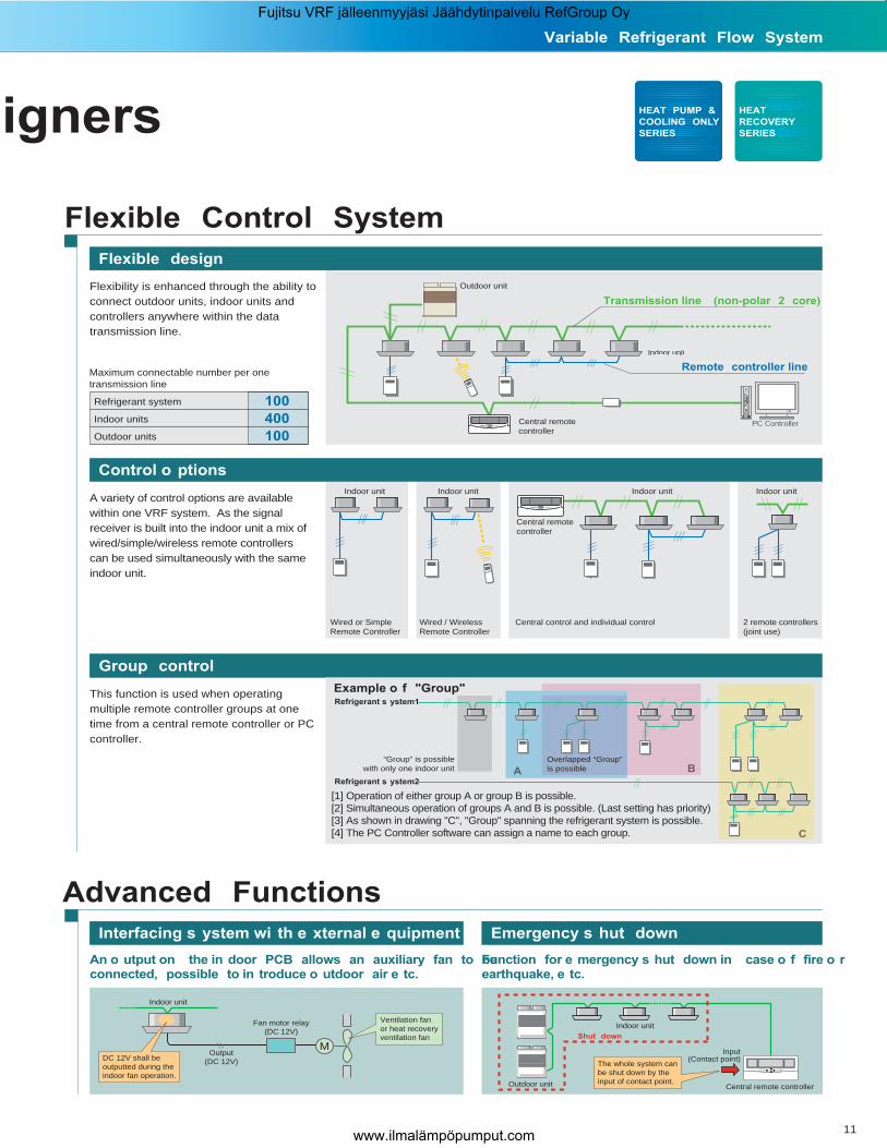
Maximum connectable number per onetransmission line
Refrigerant system 100
Indoor units 400
Outdoor units 100
Flexible Control System
Flexible design
Flexibility is enhanced through the ability to connect outdoor units, indoor units and controllers anywhere within the data transmission line.
Group control
Refrigerant s ystem1
Refrigerant s ystem2
Example o f "Group"
“Group” is possiblewith only one indoor unit
[1] Operation of either group A or group B is possible.[2] Simultaneous operation of groups A and B is possible. (Last setting has priority)[3] As shown in drawing "C", "Group" spanning the refrigerant system is possible.[4] The PC Controller software can assign a name to each group.
A BOverlapped “Group”is possible
C
Central remote controller
Wired or SimpleRemote Controller
Wired / WirelessRemote Controller
Central control and individual control
Indoor unit Indoor unitIndoor unit
2 remote controllers(joint use)
Indoor unit
Outdoor unit
Indoor unit
Remote controller line
Transmission line (non-polar 2 core)
Central remote controller
This function is used when operating multiple remote controller groups at one time from a central remote controller or PC controller.
Control o ptions
A variety of control options are available within one VRF system. As the signal receiver is built into the indoor unit a mix of wired/simple/wireless remote controllers can be used simultaneously with the same indoor unit.
Advanced Functions
An o utput on the in door PCB allows an auxiliary fan to beconnected, possible to in troduce o utdoor air e tc.
Function for e mergency s hut down in case o f fire o rearthquake, e tc.
Outdoor unit
Shut down
Indoor unit
Input(Contact point)
Central remote controller
M
Indoor unit
DC 12V shall be outputted during the indoor fan operation.
Fan motor relay(DC 12V)
Ventilation fan or heat recovery ventilation fan
Interfacing s ystem wi th e xternal e quipment Emergency s hut down
Output(DC 12V) The whole system can
be shut down by the input of contact point.
HEAT
RECOVERY
SERIES
HEAT PUMP &
COOLING ONLY
SERIES
Variable Refrigerant Flow System
Fujitsu VRF jälleenmyyjäsi Jäähdytinpalvelu RefGroup Oy
www.ilmalämpöpumput.com

12
Reduced Installation Work
Compact size
Low Piping Costs
Simple piping s ystem
Space saving
Craning into place
Piping connection
Outdoor unit goes into elavator
The outdoor unit can be lifted by crane and set down on the building roof.
Installation s pace
Space saving by setting side by side without space in between.
Offering one of the smallest footprints available the outdoor unit provides 84kW(28kW X 3) capacity within a very tight space.
For Installers
(Unit : mm)
1,050
800
1,50
0
1,30
0
650
Dimensions
1,38
0
6501,300
1Front 2
Bottom
3Right
4Back
Four-direction pipe
5.72 (Unit: m2)Setting sze
The simple piping system reduces costs by increased piping flexibility.
Cooling Only & Heat Pump Heat Reco very
Top air outlet
Back sideintake port
H (1
200m
m)
h
H (1
200m
m)
h
Front sideintake port
L2L1
10mm or more
10mm or more
300mm or more
500mmor more
FRONTSIDE
. There is no height restriction for the side wall.. The height(H) of front and rear wall should be less than 1,200mm.. If the height of wall exceeds 1,200mm by h mm, add h mm to the service space width for L1 and L2. H 1,200 : L1 500, L2 300 H 1,200 + h : L1 500 + h, L2 300 + h
10mm or more
10mm or more
10mm or more
10mm or more
300mmor more
500mm or more
FRONT SIDE
For indi vidually For continuous
Four-direction piping allows a variety of installation configurations.Easy installation and pipe direction setting.
Protective boards
Separation tube Header
Indoor unit
Indoor unit
Separation tube Header
RB unit(Multi type)
Liquid pipe
Discharge gas pipe
Suction gas pipe
RB unit(Single type)
Outdoorunit
Indoor unit
Indoor unit
Outdoorunit
Liquid pipe
Gas pipe
(Unit : mm)
TM
Fujitsu VRF jälleenmyyjäsi Jäähdytinpalvelu RefGroup Oy
www.ilmalämpöpumput.com

13
Extensive monitoring and analysing functions
Service Tool [Software] Model: UTR-YSTB
Non-polar 2-conductor transmission line prevents erroneous wiring.
Easy Wiring
Service Tool can monitor the operation of the entire VRF system.
. Operational status can be checked and analysed to detect even the smallest abnormality.
. By storing system operation status in a PC, data can be checked even when offline.
. For remotely located installations, operating data can be quickly emailed to a central station for alarm monitoring and analysis.
Easy installation
Simple connection by Transmission Adaptor and RS-232C cable (RS-232C cable field supplied). Simple installation of software using only the CD supplied.
Transmission line
By indicating the operating status and details of failures on a PCB in the outdoor unit, better service and quick and easy maintenance are possible.
A pull-out plate ensures easy compressor replacement if necessary.
Operationdisplay
Transmission line Power supply wiring
PC controller
Central remotecontroller
Indoor unit
Outdoor unit
Outdoor unit
Outdoor unit
Transmission adaptor
Transmission line
Indoor unit
Indoor unit
Power supply for outdoor and indoor units is different.
Indoor unit : 1 2W 220 - 240V 50Hz
Outdoor unit : 3 4W 380 - 415V 50Hz
Pump down can be performed from the outdoor unit using the switch on the PCB.
Easy Maintenance
Operating display (outdoor unit) Pump down controlEasy replacement
HEAT
RECOVERY
SERIES
HEAT PUMP &
COOLING ONLY
SERIES
Variable Refrigerant Flow System
Fujitsu VRF jälleenmyyjäsi Jäähdytinpalvelu RefGroup Oy
www.ilmalämpöpumput.com

1. Individual operation of the indoor units ensures that the failure of one does not affect the whole system. 2. Maintenance efficiencies are raised through the connection of a PC anywhere on the data transmission line.3. Error codes can be clearly displayed on the wired remote controller, simple remote controller, central remote control or PC controller.
14
Flexible Control System
Features of control system
Control system reliability
Configuration of control system
SystemAir Con ditioningCentral Control
Air Con ditioningIndividual Control
Outdoor unit
Indoor unit
NetworkConvertor
UTR-YSSA
Network Con vertor (BMS / Ethernet)
.Air conditioning control / monitoring
.Electricity charge calculation
.Annual operation schedule control
.Daily report / Monthly report control
.Air Conditioning control / monitoring
.Weekly timer
.Error display
Transmission line (LONWORKS® Network)
Transmission line (RS-232C Cable)
Public telephone line
Remote controller line
Remote controller line (Single System)
Ethernet Network
LONWORKS® NetworkSchedule of product release
General-purpose b uildingcontrol computer
General-purposeair conditioning control computer
Error monitoring
General-purpose air conditioningcontrol computerAir conditioning control/monitoringError monitoringConnectable to various sized BMS
Building Management
UTR-YLEA
Service Tool
UTR-YSTB
Network Con vertor (BMS / LONWORKS®)
UTR-YLLA
Transmission Adaptor (BMS / RS-232C C able)
UTR-YTMA
TransmissionAdaptor
UTR-YTMA
UTR-YOTA
UTB-YCA / UTB-GCA
PC Controller
Central Remote Controller
UTB-YLB / UTB-GLB / UTB-TLB
Wired Remote Controller
UTB-YSAUTB-GSA
UTB-YVAUTB-GVA
Wireless Remote Controller
UTB-YPA / UTB-GPA / UTB-TPA
Simple Remote Controller
Monitoring
.Refrigerant System List
.Device status Details Screen
.Device status Circuit Diagram
Error Display
VRF structure and features ensure
1. Reduced wiring as all system equipment accommodated on a single transmission line (non-polar 2-conductor).2. Total wiring length (total length of transmission line) can be extended up to 2000m (by using signal amplifier units).3. Maximum of 400 indoor units can be connected.4. Indoor units can be controlled by wired, simple, wireless, central remote controller or PC controller.5. Central control of single split type models (with exceptions) or big multi type air conditioners is possible from a central remote controller or PC controller.6. Model combinations are dictated by the building’s needs and not the system.7. The ‘simple’ remote controller is ideal for installations such as hotel guest rooms.
LONWORKS® is a registered mark of Echelon Corporation.
TransmissionAdaptor
Schedule of product release
TM
Fujitsu VRF jälleenmyyjäsi Jäähdytinpalvelu RefGroup Oy
www.ilmalämpöpumput.com
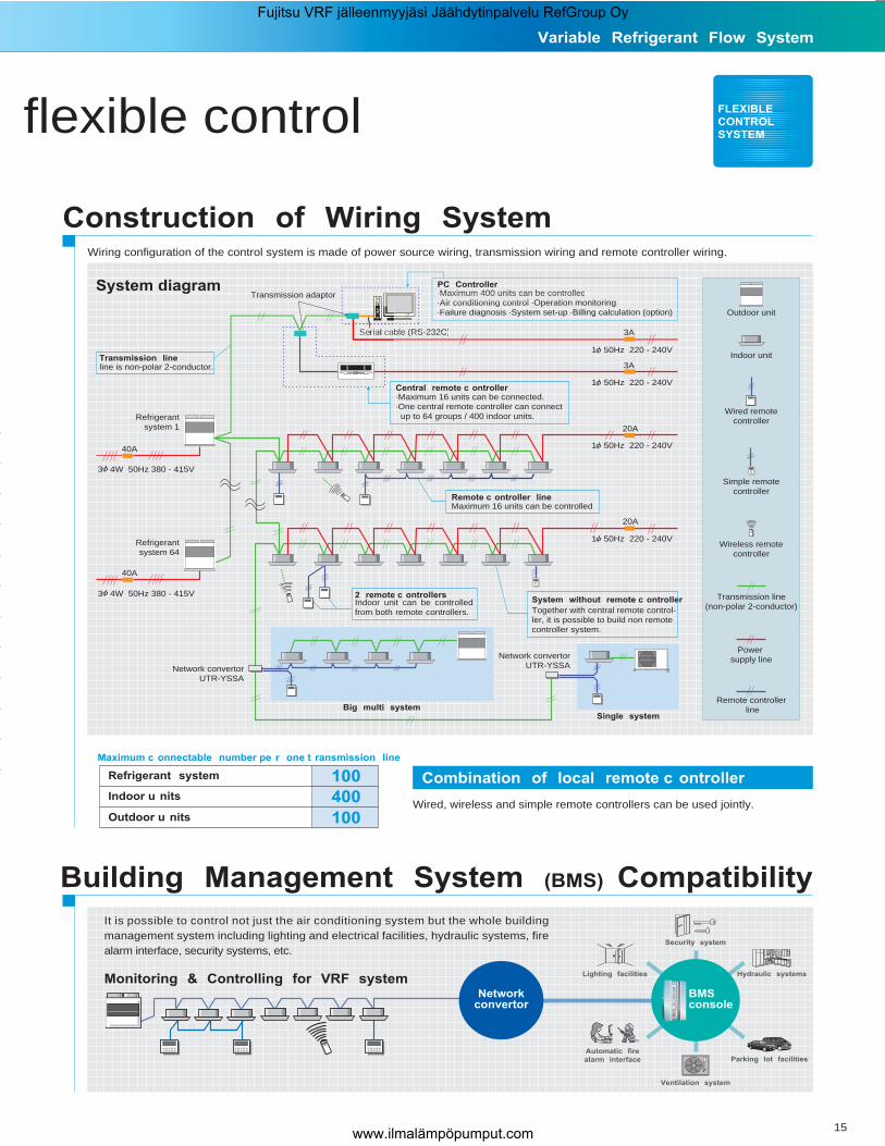
Wired, wireless and simple remote controllers can be used jointly.
Combination of local remote c ontroller
15
Construction of Wiring System
FLEXIBLE
CONTROL
SYSTEM
Wiring configuration of the control system is made of power source wiring, transmission wiring and remote controller wiring.
Maximum c onnectable number pe r one t ransmission line
Refrigerant system
Indoor u nits
Outdoor u nits
100
100
400
It is possible to control not just the air conditioning system but the whole building management system including lighting and electrical facilities, hydraulic systems, fire alarm interface, security systems, etc.
Building Management System (BMS) Compatibility
Monitoring & Controlling for VRF system
Security system
Ventilation system
Hydraulic systems
Parking lot facilities
Lighting facilities
Automatic fire
alarm interface
Networkconvertor
BMSconsole
System diagram
Outdoor unit
Indoor unit
System without remote c ontroller
Together with central remote control-ler, it is possible to build non remote controller system.
Maximum 16 units can be controlled
Refrigerant system 1
2 remote c ontrollers
Remote c ontroller line
3 4W 50Hz 380 - 415V
3 4W 50Hz 380 - 415V
Transmission line
Transmission line(non-polar 2-conductor)
Power supply line
Remote controller line
PC ControllerPC Controller..Maximum 400 units can be controlledMaximum 400 units can be controlled.Air conditioning controlAir conditioning control .Operation monitoring.Failure diagnosis F il di ig .System set-up .Billing calculation (option)
.Maximum 16 units can be connected.
.One central remote controller can connect up to 64 groups / 400 indoor units.
Indoor unit can be controlledfrom both remote controllers.
Wireless remotecontroller
Transmission adaptor
ble (RS-232C)22SRebble (RS-232C)
40A
40A
1 50Hz 220 - 240V
1 50Hz 220 - 240V
1 50Hz 220 - 240V
1 50Hz 220 - 240V
Refrigerant system 64
Network convertorUTR-YSSA
Single system
Simple remotecontroller
line is non-polar 2-conductor.
Network convertorUTR-YSSA
Big multi system
20A
20A
3A
3A
Central remote c ontroller
Wired remotecontroller
flexible control
Variable Refrigerant Flow System
Fujitsu VRF jälleenmyyjäsi Jäähdytinpalvelu RefGroup Oy
www.ilmalämpöpumput.com

16
.Up to 400 indoor units/400 groups/400 remote controller groups can be connected into one system for large scale buildings or hotels..A high degree of building air conditioning management is possible including electricity consumption calculation and numerous data management functions as well as standard equipment monitoring and control.
Rotating 3-D DisplayWhen monitoring and controlling the operation by whole building.
Floor Layout DisplayWhen monitoring and controlling the operation by each floor or group.
List Ta ble DisplayWhen monitoring and controlling each unit in detail.
Operation Control
PC Controller [software]
High performance a nd optimum control systemfor various building a pplications
UTR-YOTA
Controller featuresAir conditioning central control
Functions
Central building monitoring and control
The 6 functions of the standard controller can be locked from the PC: all functions, timer mode, operating mode, temperature setting, filter reset, on/off.All functions can be controlled via the PC Controller only.
Central control
User Friendly Operation.Utilises Windows® 2000 so is as easy to use as a standard PC..Operational status can be colour coded for easy recognition, e.g. On/green, Off/red, test/orange, error/flashing..Operational status can be displayed to suit the user.
.Detailed settings can be programmed for each whole building/group/remote controller group or individual indoor unit.
.The PC and central remote controller can be used together, allowing system control from two or more locations if required.
TM
Fujitsu VRF jälleenmyyjäsi Jäähdytinpalvelu RefGroup Oy
www.ilmalämpöpumput.com
17
FLEXIBLE
CONTROL
SYSTEM
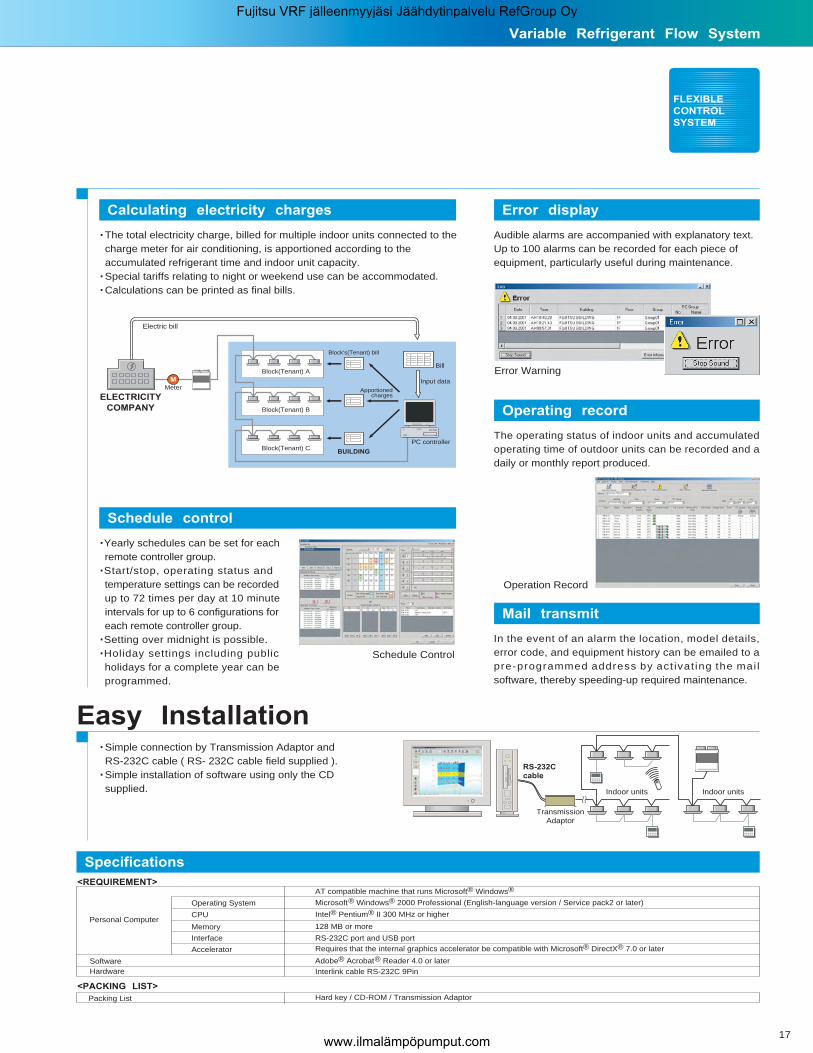
Specifications
Easy Installation
Calculating electricity charges
.The total electricity charge, billed for multiple indoor units connected to the charge meter for air conditioning, is apportioned according to the accumulated refrigerant time and indoor unit capacity..Special tariffs relating to night or weekend use can be accommodated..Calculations can be printed as final bills.
Schedule control
.Yearly schedules can be set for each remote controller group..Start/stop, operating status and temperature settings can be recorded up to 72 times per day at 10 minute intervals for up to 6 configurations for each remote controller group..Setting over midnight is possible..Holiday settings including public holidays for a complete year can be programmed.
Error display
PC controller
ELECTRICITY
COMPANY
Electric bill
Input data
Bill
Block's(Tenant) bill
M
Meter Apportionedcharges
Block(Tenant) A
Block(Tenant) B
Block(Tenant) CBUILDING
Error Warning
Operation Record
RS-232C cable
Indoor unitsIndoor units
Schedule Control
Audible alarms are accompanied with explanatory text.Up to 100 alarms can be recorded for each piece of equipment, particularly useful during maintenance.
Operating record
The operating status of indoor units and accumulated operating time of outdoor units can be recorded and a daily or monthly report produced.
Mail transmit
In the event of an alarm the location, model details, error code, and equipment history can be emailed to a pre-programmed address by act ivat ing the mai l software, thereby speeding-up required maintenance.
.Simple connection by Transmission Adaptor and RS-232C cable ( RS- 232C cable field supplied )..Simple installation of software using only the CD supplied.
TransmissionAdaptor
<REQUIREMENT>
Microsoft® Windows® 2000 Professional (English-language version / Service pack2 or later)
AT compatible machine that runs Microsoft® Windows®
Operating System
Intel® Pentium® II 300 MHz or higherCPU
128 MB or moreMemory
RS-232C port and USB portInterface
Accelerator Requires that the internal graphics accelerator be compatible with Microsoft® DirectX® 7.0 or later
Adobe® Acrobat® Reader 4.0 or laterSoftware
Hard key / CD-ROM / Transmission Adaptor Packing List
Interlink cable RS-232C 9PinHardware
Personal Computer
<PACKING LIST>
Variable Refrigerant Flow System
Fujitsu VRF jälleenmyyjäsi Jäähdytinpalvelu RefGroup Oy
www.ilmalämpöpumput.com

TM
18
.Up to 400 indoor units/400 remote controller groups/64 groups can be controlled by one system..Up to 16 central remote controllers can be connected into one system allowing operation and monitoring to be achieved from the central control room, at each floor, by each tenant, or in the plant room.
Central Remote Controller
Functionality in a compact housing with built-in weekly time r
UTB-YCA / UTB-GCA
Controller featuresAir conditioning central control
Functions
Control up t o 400 in door units
The 6 functions of the standard remote controller can be locked from the Central Remote Controller: all functions, timer mode, operating mode, temperature setting, filter reset, on/off.All functions can be controlled via the Central Remote Controller only.
Central control
.Central remote controller can control the system by selecting All Groups, User Defined Groups or Individual Remote Controller Groups
.Accurate control of functions such as Start/Stop, Operating Mode, Temperature, and Air Velocity ensures occupancy comfort.
Easy Operation.Control functions are divided into three areas: Timer Control, Central Control and Operational Control, which are clearly displayed..A large liquid crystal display clearly indicates which indoor unit is currently in operation.
TIMER
CONTROL
AREA
CENTRAL
CONTROL
AREA
OPERATION
CONTROL
AREA
All Control Mode Group Control Mode Individual Control Mode
Individual
AllGroup
Fujitsu VRF jälleenmyyjäsi Jäähdytinpalvelu RefGroup Oy
www.ilmalämpöpumput.com

Setting Example (2)
8 C
5 CON
OFF OFF
ON
Variable Refrigerant Flow System
19
FLEXIBLE
CONTROL
SYSTEM
Built-in Weekly Timer
.The timer function, which can control up to 400 indoor units, provides detailed scheduling for each remote controller group..A simple approach to system configuration reduces wiring costs.1. Possible to set different ON / OFF time twice a day for each day of the week.2. Possible to set time in 10 minutes steps.3. Time operation for a reserved day can be cancelled temporarily by pressing the "DAY OFF" button in advance.4. Time setting can be carried over to the next day.5. Copy and Paste can be used for time settings for each day.
Error display
Up to 62 error codes can be displayed. The last 2 error codes can be displayed, allowing easy inspection, service and maintenance.
Advanced functions
Anti Freeze :
When the room temperature drops to5˚C or less the heatingis automatically switched on.
Memory : Central remote controller maintains original settings for indoor units. This data can easily be transmitted to the system even after the operating conditions have been changed.
During COOLING operationWhen the ENERGY SAVE is pressed, the thermostat setting isautomatically raised 1˚C every 60minutes, until the thermostat israised a total of 2˚C.
During HEATING operation When the ENERGY SAVE is pressed, the thermostat setting isautomatically lowered 1˚C every30 minutes, until the thermostat islowered a total of 4˚C.
Energy Saving Operation :
Weekly schedule Example : Office
Operation : Monday~Friday 8:00~12:00 and 13:00~18:00
Mon Tue Wed Thu Fri SatSun1H
1H
0.5H
0.5H
0.5H
0.5H
Behind ceiling
Possible to extend up to 5m. (Max)
Transmission Adaptor
(optional service parts)
ControlPanel
Setting Example (1)
Wall
ControlPanel
Transmission
Adaptor
Connecting cable
Power Supply 220-240V(Use a 3A or more fuse)
Transmission line
Transmission
Adaptor
Control Panel
27 C
25 C
26 C
23 C
22 C
21 C
20 C
19 C
Control Panel
Specifications
220-240V 50-60HzPower Supply
4.8Power Consumption (W)
-Fuse Capacity (A)
143 x 296 x 22Dimension (H x W x D)(mm)
0.55Weight (kg)
-Packing Size (H x W x D)(mm)
-Transmission Line
Control Panel / Transmission Adaptor / Connecting Cable
Transmission Adaptor
220-240V 50-60Hz Single phase
3.9
3
100 x 288 x 106
2.0
145 x 330 x 190
Shielded Non-polar, 2 core cable
-Packing List
Simple and Convenient Installation.The controller can be installed on any flat surface..The control panel and transmission adaptor can be installed separately.Also, the main unit can be either built inthe wall or exposed, which allows forflexible installation.
Energy save
Energy save
Fujitsu VRF jälleenmyyjäsi Jäähdytinpalvelu RefGroup Oy
www.ilmalämpöpumput.com
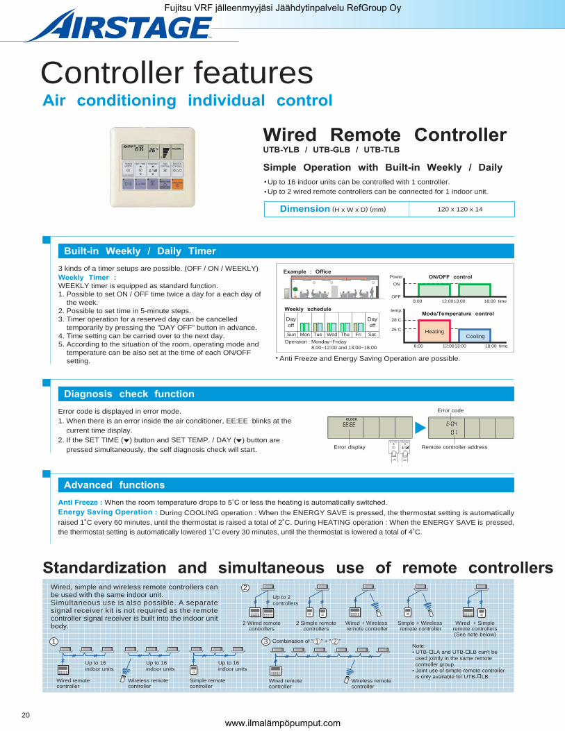
Error code is displayed in error mode.1. When there is an error inside the air conditioner, EE:EE blinks at the current time display.2. If the SET TIME ( ) button and SET TEMP. / DAY ( ) button are pressed simultaneously, the self diagnosis check will start.
20
Controller featuresAir conditioning individual control
Error code
Remote controller address
CLOCK
TEMP./DAYSET TIME
Error display
Diagnosis check function
During COOLING operation : When the ENERGY SAVE is pressed, the thermostat setting is automatically raised 1˚C every 60 minutes, until the thermostat is raised a total of 2˚C. During HEATING operation : When the ENERGY SAVE is pressed, the thermostat setting is automatically lowered 1˚C every 30 minutes, until the thermostat is lowered a total of 4˚C.
Advanced functions
Standardization and simultaneous use of remote controllersWired, simple and wireless remote controllers can be used with the same indoor unit.Simultaneous use is also possible. A separate signal receiver kit is not required as the remote controller signal receiver is built into the indoor unit body.
Wireless remotecontroller
Wired remotecontroller
Up to 16 indoor units
Up to 16 indoor units
Up to 16 indoor units
Simple remotecontroller
1 Combination of " " + " "
Wired + Wireless remote controller
2 Wired remotecontrollers
Up to 2 controllers
2 Simple remotecontrollers
Simple + Wireless remote controller
Wireless remotecontroller
Wired remotecontroller
Wired + Simpleremote controllers(See note below)
2
3 1 2
Dimension (H x W x D) (mm) 120 x 120 x 14
Up to 16 indoor units can be controlled with 1 controller.Up to 2 wired remote controllers can be connected for 1 indoor unit.
Wired Remote Controller
Simple Operation with Built-in Weekly / Daily
UTB-YLB / UTB-GLB / UTB-TLB
Built-in Weekly / Daily Timer
Anti Freeze and Energy Saving Operation are possible.
3 kinds of a timer setups are possible. (OFF / ON / WEEKLY)Weekly Timer :
WEEKLY timer is equipped as standard function.1. Possible to set ON / OFF time twice a day for a each day of the week.2. Possible to set time in 5-minute steps.3. Timer operation for a reserved day can be cancelled temporarily by pressing the "DAY OFF" button in advance.4. Time setting can be carried over to the next day.5. According to the situation of the room, operating mode and temperature can be also set at the time of each ON/OFF setting.
Example : Office
Weekly schedule
ON/OFF control
Mode/Temperature control
Operation : Monday~Friday 8:00~12:00 and 13:00~18:00
Mon Tue Wed Thu Fri SatSun
Dayoff
Dayoff
25 C
OFF
ON
28 C
8:00 12:0013:00 18:00
temp.
Power
time
8:00 12:0013:00 18:00 time
HeatingCooling
Note:• UTB- LA and UTB- LB can't be used jointly in the same remote controller group.• Joint use of simple remote controller is only available for UTB- LB.
TM
Fujitsu VRF jälleenmyyjäsi Jäähdytinpalvelu RefGroup Oy
www.ilmalämpöpumput.com

21
158 x 56 x 20
189 x 56 x 16
Handy Type
Wall-Fixed / Handy TypeDimension (H x W x D) (mm)
Built-in Daily T imer
A B C D
Easy installation a nd operation
Sleep Timer :
To prevent excessive warming or cooling during sleep, the SLEEP timer function automatically modifies the thermostat setting in accordance with the time setting..Energy Save Operation is possible.
Select from 4 different timer programs : On / Off / Program / Sleep
FLEXIBLE
CONTROL
SYSTEM
Program Timer :
The PROGRAM timer allows you to integrate OFF timer and ON timer operations in a single sequence. The sequence can involve one transition of OFF timer and ON timer, within a 24 hours period.
Wireless Remote Controller
Simple Operation with a Choice of 4 Daily
Wall-Fixed / Handy Ty pe : UTB-YSA / UTB-GSA
Handy Ty pe : UTB-YVA / UTB-GVA
Simple Remote ControllerUTB-YPA / UTB-GPA / UTB-TPA
User friendly operation
.Concentrates on the basic operations such as On/Off, Fan Control, Operation Mode Switching, and Temperature Setting..A large Start/Stop button is provided in the centre of the remote controller unit for easy operation..Background light enables easy operation in a darkened room..Diagnostics are carried out during the ‘stop’ mode following an error display.
Slim, compact design
.Slim design only 14mm depth for built-in mounting or wall-mounted..Can be mounted on the European Mounting Box (Installation dimension: 60mm) or the JIS Built-in Box (Installation dimension: 83.5mm).
.Up to 16 indoor units can be controlled with one remote controller.
.Suitable for hotels or offices which have many visitors coming in and going out and do not require detailed functions.
Compact r emote controller concentrates on t he basic functions r equired
A B C D
A B C D
Confusion
Code change
COOL
FANDRY
HEAT
AUTO AUTOHIGHMEDLOWQUIET
TIMER
TIMER RESET
CLOCK SLEEP
ENERGY SAVE
CF
AMPM
ONOFFOFFON
LOW HIGH
H M
Wall-Fixed / Handy Ty pe.Can be handy or wall mounted.
.Code selector switch prevents indoor unit mix-up. (Up to 4 codes can be set.)
.Wide and precise transmitting range. (3 LEDs inside)
Handy Ty pe
Wall-Fixed /
Handy Ty peHandy Type
120 x 75 x 14 Dimension (H x W x D) (mm)
HANDY SETTING WALL FIXING
Holder Holder
1.
2.
1. Press the MASTER CONTROL button for more than five seconds to start the code change.
3. Press the MASTER CONTROL button again to end the code change.
2. Press the (+) or (-) button to select the desired code.
Variable Refrigerant Flow System
Fujitsu VRF jälleenmyyjäsi Jäähdytinpalvelu RefGroup Oy
www.ilmalämpöpumput.com

Duct TypeCompact Duct TypeCassette TypeCompact Cassette Type
see p age 25see p age 24 see p age 26 see p age 26
ModelAU7 / AU9 / AU12 / AU14 / AU18
ModelAU20 / AU25 / AU30 ( Slim Type ) AU36 / AU45 / AU54
ModelAR7 / AR9
ModelAR12 / AR14 / AR18
ModelAR25 / AR30 / AR36 / AR45
Full Range of Indoor Units
Slim Type
Room-temperature feedback control
22
Room te mperature feedback c ontrol
Comfortable temperature control can be achieved by feedback control of intake air temperatures and the opening of electronic expansion valve.
Energy saving operation
(kW)
Capacity
Type
(BTU/h)
2.80 9,000
10.50 36,000
4.05 14,000
3.60 12,000
6.80 24,000
Common features
17.00 60,000
12.70 45,000
5.70 20,000
5.30 18,000
Energy saving operat ion is possible by changing the operation capacity according to the remote controller's setting.
COOLING operation :The thermostat setting is automatically raised 1˚C every 60 minutes, until the thermostat is raised a total of 2˚C.
HEATING operation :The thermostat setting is automatically lowered 1˚C every 30 minutes, until the thermostat is lowered a total of 4˚C.
Auto-Changeover
The unit automatically switches between heating and cooling modes based on your temperature setting and the room temperature.
A full and c omplete range of indoor u nits is available
2.15 7,000
14.10 54,000
8.80 30,000
7.05 25,000
Slim Type
Slim Type
Slim Type
Set temp.
Conventional controlFeedback control
+2
-2
+1
-1
Set Temp.
COOLING
HEATING: Comp. ON : Comp. OFF
TM
Fujitsu VRF jälleenmyyjäsi Jäähdytinpalvelu RefGroup Oy
www.ilmalämpöpumput.com

Wall Mounted Type Ceiling Wall TypeCeiling TypeFloor & Ceilin gUniversal Type
High St atic PressureDuct Type
see page 27see page 27 see page 28 see page 28 see page 29
ModelAB12 / AB14 / AB18 / AB24
ModelAR36(H) / AR45(H) / AR60(H)
ModelAB30 / AB36 / AB45 / AB54
ModelAW7 / AW9 / AW12 / AW14 / AW18 AW24 / AW30
ModelAS18 / AS24 / AS30
23
Anti Freeze
In cold regions, room temperature drops at night. This function prevents freezing of the water and other parts.
Power boost start
The time required to reach the set temperature from start up has been shortened for cooling operation.In comparison with conventional type, the power at start up has been increased by 130% for heat pump & cooling only models.
5 C 8 C
ON
OFF OFF
ON
8 C
5 C
Heating operation (Automaticaly)
INDOOR
UNIT
By setting this feature, heating operation is automatically started when the room temperature falls to 5 C.
Heating operation is automatically stopped when the room temperature reaches 8 C.
COOLING
Time
Settemperature
Tem
pera
ture VRF type
Conventional type
Variable Refrigerant Flo w System
Fujitsu VRF jälleenmyyjäsi Jäähdytinpalvelu RefGroup Oy
www.ilmalämpöpumput.com

Compact Cassette / Cassette Type
24
Large air flow at reduced noise outputachieved by incorporating a large diametervariable pitch turbo fan.
Compact Cassette Type
Models
AU7 / AU9 / AU12 / AU14 / AU18
Features
Compact grille fits European ceiling panel (600 x 600 mm). 4-step s wing
Auto air flow direction and auto swing
By placing the electrical component box inside the unit easymaintenance is assured.
Compact size Comfortable air flow
Easy ma intenance
Low noise
Movement of the flap angle can be changed via a simple switch during installation, thereby preventing uncomfortable draughts.
Draught p revention
Punch Hall grille
Electricalcomponent box (Built-in)
600mm
600m
m
2~4 way a ir flow system
Select 2-way, 3-way or 4-way air flow to suit your needs.
580mm
250m
m20
mm
7 blades Fan
298m
m
4-way3-way2-way
400m
m
Condensate p umplift to 400mm
Compact design for easy installation and maintenance
Wide opening foreasy maintenance.
Detachable,washable filter
Normal position Draught preventionposition
36 - 65Flap angle
25 - 65Flap angle
TM
Fujitsu VRF jälleenmyyjäsi Jäähdytinpalvelu RefGroup Oy
www.ilmalämpöpumput.com

25
INDOOR
UNIT
Compact body ensures space saving installation.A slender fit option is available where ceiling void space is limited.
Flexible installation
Easy maintenance
Cassette Type
Models
Features
AU36 / AU45 / AU54 285 250
AU20 / AU25 / AU30 235 200
Ha Hb
Standard settin g Slender settin g
Standard
Suitable ceilin g height (m)
4-step s wing
Auto air flow directionand auto swing
Comfortable air flow
Noise output has been dramatically lowered.. Improved turbo fan shape (aerodynamic design) . Expanded air distribution. Low internal resistance . Moulded fan motor
Improved noise le vel and air distri bution
High ceiling mode (air flow up) and low-noise (air flow down) can be switched according to the height of the ceiling and other conditions by means of a PCB DIP switch.
Air-flow volume can be s witched
Select 2-way, 3-way or 4-way air flow to suit your needs.
Wide air flow
Larger air flap distributes the outlet air flow a longer distancein the horizontal direction.
Duct connection hole o pening
Fresh air can be introducedthrough this opening.
Conditioned air can be distributed bymeans of a distribution duct.
4-way3-way2-way
TwDistributionduct
Distribution
duct
Fresh air
Condensate pumplift to 800mm
800m
m
High 1 ceilin gHigh 2 ceilin g Low ceilin g
2.5-3 3-3.5 more than3.5
less than2.5
Slim cassette, designed for limited ceiling space
Movement of the flap angle can be changed via a simple switch during installation, thereby preventing uncomfortable draughts.
Draught prevention
Normal position Draught preventionposition
36 - 65Flap angle
25 - 65Flap angle
AU20 / AU25 / AU30
AU36 / AU45 / AU54
Simple
maintenance
Long-life
filter
Detachable,
washable filter
and intake grille.
Long-lifefilter
High efficiency, long-life filter extends the cleaning cycle.
The control box is easy accessible for maintenance work. Wide opening for easy access.
Wide opening andlong-life filter.
Slim Type
Hb
Slender settin gStandard settin g
Ha
StepsSwing
4 ste ps s wing 4 ste ps s wing
4 3 2 1
4321
Variable Re frigerant Flow System
Fujitsu VRF jälleenmyyjäsi Jäähdytinpalvelu RefGroup Oy
www.ilmalämpöpumput.com

Compact Duct / Duct / High Static Pressure Duct / Floor & Ceiling Uni
26
Ultra-slim duct air conditionerfor very low ceilings
Choice of installationCan be suspended from the ceiling or placed on the floor
Low noise level
7 9
A low noise level has been achieved for each capacity
0 / 39.6
31
340/290
Pa
dB(A)
m3 / h
Static pressure(Normal/Max.)
Volume o f air-flow(High/Low)
Noise level(Low s peed)
30
460/360
Model
26 26 33
12 14 18
420/360 640/480 750/640
Easy to ins tall (Universal type)
Ceiling concealed
Ultra-slim duct air conditioner for easy installation
Compact design
Whether installed in the ceiling void or a false ceiling, this model provides savings in space and reductions in noise.A single indoor unit can serve several rooms.
Savings in s pace and reduction in noise
Ultra-slim models for ve ry low ceilings
Piping can be run in almost any direction
Installation s tyles
Optional parts
Anchor boltsHanger bolts
Direct ins tallationSuspended ins tallation
Flexible ins tallation
27cm
Floor conc
AR7 / AR9 AR12 / AR14 / AR18
Compact Duct Type
Models
AR7 / AR9
AR12 / AR14 / AR18
Features
Duct Type
Models
AR25 / AR30 / AR36 / AR45
Features
Flange (square) Flange (round) Flexible ductLong life filterRemote sensor unit
UTD-SF045TUTD-RF204UTD-RD202UTD-LF270UTD-RS100F
Optional parts
Remote sensor unit UTD-RS100F
Embedded in Ceiling Hanging from Ceiling
Coupling pipe assy
Control box
27cm
Drain port
Aux pipe
TM
Fujitsu VRF jälleenmyyjäsi Jäähdytinpalvelu RefGroup Oy
www.ilmalämpöpumput.com

versal Type
27
The slim and lightweight design allows the unit to be suspended from the ceiling or installed at floor level.
A high static pressure duct type indoor unit
INDOOR
UNIT
Installed in the ceiling void this model provides savings in space and reductions in noise.A single indoor unit can serve several rooms.
Savings in s pace and reduction in n oise
Fan motor maintenance can be performed from the top and the bottom.
Easy maintenance
Easy inst allation
High st atic pressure
Top access
Bottom access
Control b ox cover (Electrical parts access)
Maintenance panel (Thermistor access)
Maintenance panel (Fan motor access)
The pipe can be connected in any direction by using theL-shaped auxiliary pipe.
Recommended external static pressure : 196 Pa (Max. 300Pa)
Easy installation by suspension
High Static Pressure Duct Type
Models
AR36(H) / AR45(H) / AR60(H)
Features
Double-flap ‘Super Vane’ with newly developed special configuration boosts air flow sending cool air quickly to every corner of the room.
Super vane
This function is common to all indoor unit types except the duct type.
Auto-closing l ouver
Flexible inst allation
(unit: mm)
990 199
655
Ceiling
Floor
A combination of up/down and right/left directional swing allowsthree-dimensional air direction control.
Double auto s wing
Symmetrical, slim andcompact design
Compact design
Floor & Ceiling Universal Type
AB12 / AB14 / AB18 / AB24
Features
Models
Outlet chamberFlexible ductLong life filterRemote sensor unit
UTD-BC200UTD-RD202UTD-LF400UTD-RS100F
Optional parts
To t op
To rear
To si de
Auxiliary
pipe assembly
To b ottomTo bottomTo b ottom
4
45
3
3
22 1
1
UP and D OWNRIGHT and LEFT
SWINGSWING
5 steps sele ctable 4 steps sele ctable
Variable Refrigerant Fl ow System
Fujitsu VRF jälleenmyyjäsi Jäähdytinpalvelu RefGroup Oy
www.ilmalämpöpumput.com

28
Ceiling / Wall Mounted / Ceiling Wall Type
Models
Features
Other features include continuationof the functions of the existing wall mounted type.
Wall Mounted Typ e
AS18 / AS24 / AS30
.Double auto swing
.2-way draining route
.Hi : 44dB (Existing model : 47dB ) - 24type actual data.High efficiency fan construction 7mm Lambda type evaporator improves the airflow path.Large independently driven power diffuser
7 lambda type evaporator
Large independently driven power diffuser
Larger space at base of housing means extra 15%piping space.
Easy installation
Others
Large independently driven p ower diffuser used
Multi air flow
Low noise
High efficiency, long-life filter extends the cleaning cycle by a factor of two.
Long-life filter
Optional drain lift-up mechanism allowsmore flexible installation.
Condensate lift-up mechanism
Open Concealed Wall mounted
Installation
Double auto swing and wide air flow
Fresh air intake
OutdoorIndoor
Freshair
Ceiling Type
AB30 / AB36 / AB45 / AB54
Models
Features
‘Double auto swing’ feature providesomni-directional air flow control.
Ultra-slim design that beliesthe extra wide air flow.
Optional parts
Drain water riser kit UTR-DPB241
4
3
2
1
5 steps selectable
Up and downRight and left
Cooling
Heating
Horizontal concentration and other air direction control
Wide down flow
Steps
Swing
43
2
1
Largeindependently drivenpower diffuser
43
2
1
TM
Fujitsu VRF jälleenmyyjäsi Jäähdytinpalvelu RefGroup Oy
www.ilmalämpöpumput.com

29
. Long-life filter can be removed with one touch.
. Long-life filter extends the cleaning cycle by a factor of three.
Long-life filter
. Double auto swing/Right and left , up and down
. 2-way draining ro ute
. Air purifying filter (optional)
Others
High output and high efficiency are achieved byusing a DC motor.
High efficiency
Introduction of the top air intake reduces the curvature of the air flow path thereby achieving lower air resistance, lower noise and larger air volume.
Larger, wider airflow
Fresh air can be introducedthrough the air-intake opening.
Fresh air int ake
Drain pan can be easily removed for thorough washing without re-moving the unit from the wall.
Easy maintenance
One-touch long-life filter
Removable andwashable drain pan
(m) (m)
0
1234
7High efficiencyheat exchanger
High efficiencyDC motor
Indoor Outdoor
Fresh air
Low noise
Existing louver New quiet louver
0
4
0
346
Outlet louverreducesannoying noise
Suppressing the turbulence by providing vertical grooves on the quiet louver and the right/left louver reduces annoying noise.
Large airflow and lownoise achieved by top airintake.
Ceiling Wall Type
AW7 / AW9 / AW12 / AW14 / AW18 / AW24 / AW30
Models
Features
Attractive housing with discreet air intake.
INDOOR
UNIT
Variable Refrigerant Flow System
Fujitsu VRF jälleenmyyjäsi Jäähdytinpalvelu RefGroup Oy
www.ilmalämpöpumput.com

Specifications
30
Noise Level (Sound Pressure)
m3/h
W
kW
dB (A)380V
415V
kg
kW
kW
W/W
mm
kg
r.p.m.
m
mm
28.0
31.5
9.0
8.5
3.7
Plate Fin Coil
730
360
9800
Propeller x 2
150 x 2
1.5/3.4/4.9
285
321
57
R407C R22
12
22.4
25.2
7.2
7.6
3.3
1.5/2.5/4.8
278
314
56
10
28.0
-
9.0
- -
-
3.1
-
1.5/3.4/4.9
284
320
57
12
22.4 28.0 22.4 28.0 22.4
31.5 25.2 -
9.0 7.2 9.0 7.2
8.5 7.0
3.7 3.6
7.2
1.5/2.5/4.8 1.5/3.7/5.0 1.5/2.5/4.8 1.5/3.7/5.0 1.5/2.5/4.8
277
313
56
296
332
57
278
314
56
292
328
57
274
310
56
10 12 10 12 10
3 phase, 380 - 415V, 50Hz
Internal Protector(OCR) / High Pressure Relief Valve
1,380 x 1,300 x 650
1,535 x 1,400 x 770
12.7
28.58
100
50
-15 to 52 21 to 52
- -15 to 21 -˚C
Refrigerant Type : R407C
AO90TPBMF
AO72TPBMF
AO90EPBMF
AO72EPBMF
Refrigerant Type : R22
AO90RPBMF
AO72RPBMF
AO90APBMF
AO72APBMF
55 54 55 54 55 54 55 54
Air Circulation
Liquid
Suction Gas
Cooling
Heating
Gross
Compressor
Refrigerant
Weights
Dimensions(H x W x D)
Charge
Type
Power Source
Model
Total CapacityCooling
Heating
E.E.R.
Cooling
Heating
Fan Motor Output
High
Cooling
Heating
Total Input Watts
Motor Output
Net
Gross
Net
Protection
Heat Exchanger
Fan Speed High
Fan Type x Qty
Low
Max Length
Max Height
Operation Range (Outdoor)
Pipe
Size
Refrigerant
Pipe
Operation Range (Outdoor)
306
343
57
R407C
10.0
12.7
19.05
28.58
100
50
-5 to 52
-15 to 21
3 phase, 380 - 415V, 50Hz
28.0
31.5
9.4
10.0
2.98
3.15
730
360
9,800
Plate Fin Coil
Propeller x 2
150 x 2
1.5 / 3.4 / 5.0
1,380 x 1,300 x 650
1,535 x 1,400 x 770
Internal Protector (OCR) High Pressure Relief Valve
kg
mm
m
Size
Liquid
Discharge Gas
Suction Gas
˚C
Max. Length
Max. Height
Cooling
Heating
Type
Charge
Heat Pump & Cooling Only Ty pe
Heat Recovery Type
kW
kW
W / W
r.p.m.
m3/h
W
kW
mm
kg
dB (A)
Refrigerant Type : R407CModel
AO90MPAMF
Power Source
Total Capacity
Total Input Watts
E.E.R.
Fan Speed
Air Circulation
Heat Exchanger
Fan Type x Qty
Fan Motor Output
Dimensions (H x W x D)
Weights
Noise Level (Sound Pressure)
Compressor
Cooling
Heating
Cooling
Heating
Cooling
Heating
High
High
Low
Protection
Net
Motor Output
Gross
Net
Gross
-15 to 21
Note : Specifications are based on the following conditions. Cooling : Indoor temperature of 27˚CDB/19˚CWB, and outdoor temperature of 35˚CDB/24˚CWB. Heating : Indoor temperature of 20˚CDB/(15)˚CWB, and outdoor temperature of 7˚CDB/6˚CWB.
TM
Fujitsu VRF jälleenmyyjäsi Jäähdytinpalvelu RefGroup Oy
www.ilmalämpöpumput.com

Note : Specifications are based on the following conditions. Cooling : Indoor temperature of 27˚CDB/19˚CWB, and outdoor temperature of 35˚CDB/24˚CWB. Heating : Indoor temperature of 20˚CDB/(15)˚CWB, and outdoor temperature of 7˚CDB/6˚CWB.
31
Compact Duct Type / Duct Type
220-240V~50Hz
6.35
9.53 15.8812.7
2.15 2.80 3.60 4.00 5.00
7,400 9,600 12,300 13,700 17,100
2.45 3.10 4.10 4.50 5.45
8,400 10,600 14,000 15,400 18,600
28 52 50
0.13 0.23 0.22
0.15 0.27 0.26
530 580 640
480 520 540
410 460 470
630 690 750
570 610 640
480 540 540
Turbo x 1
Plate Fin Coil
230 x 570 x 570
280 x 710 x 750
246 x 830 x 830
355 x 1,060 x 1,025
296 x 830 x 830
455 x 1,060 x 1,025
18
23
34
44
40
47
Flare
18 to 30
16 to 30
9 10 18
38 41 44
35 37 38
31 34 35
9.53
5.70
19.500
5.80
19,800
104
0.60
0.72
1,000
840
700
450
390
330
7.05
24.100
7.85
26,800
124
0.64
0.77
1,100
940
780
490
430
360
8.80
30,000
9.10
31,100
140
0.67
0.80
1,200
1,050
840
540
480
390
37 90
41 43 46
37 40 43
33 3735
Compact Ca ssette Type / Ca ssette Type
Compact Cassette Type Cassette TypeAU7 AU9 AU12 AU14 AU18 AU20 AU25 AU30
10.5
35,800
10.7
36,500
175
0.92
1.10
1,500
1,300
1,100
580
500
420
48
44
41
AU36
12.7
43,400
13.7
46,800
190
0.94
1.12
1,650
1,450
1,200
620
550
470
49
47
43
AU45
14.1
48,100
15.8
53,900
219
0.95
1.14
1,780
1,550
1,300
680
580
500
52
48.5
45
AU54Model
Cooling Capacity
Power Source
Heating Capacity
Input
Current
Max. Current
Air Circulation
Fan Speed
Fan Motor Output
Noise Level (Sound Pressure)
Heat Exchanger
Dimensions (H x W x D)
Weights
Pipe Size
Pipe Connection Method
Fan Type x Q'ty
Operation Range
Med
Low
High
Med
Low
High
Med
Low
High
Gross
Net
Gross
Net
Gas
Liquid
Heating
Cooling
A
A
W
BTU / h
kW
BTU / h
kW
m3/h
r.p.m.
kg
mm
mm
˚C
dB (A)
W
19.05
2.15 2.80 3.50 4.00 5.30
7,300 9,600 11,900 13,700 18,100
2.45 3.10 4.10 4.80 5.60
8,400 10,600 14,000 16,400 19,100
40 43 34 50 62
0.21 0.20 0.23 0.27
0.25 0.24 0.27 0.32
340 420 460 640 750
320 390 430 560 700
290 360 390 480 640
780 960 640 840 960
720 880 610 740 900
660 810 580 650 840
Sirocco x 2Sirocco x 1
217 x 953 x 595
324 x 1,075 x 686
25
29
217 x 663 x 595
324 x 785 x 686
18
22
21
31 35 28 34
12 14 16 18
36
28 33 27 32 35
26 31 26 30 33
7.05
24,100
7.85
26,800
155
0.68
0.84
1,200
1,100
1,000
890
820
745
8.80
30,000
9.10
31,000
240
1.06
1.58
1,650
1,550
1,350
1,240
1,140
1,040
10.5
36,000
10.7
36,500
265
1.16
1.58
2,000
1,800
1,600
1,280
1,200
1,130
12.7
43,500
13.7
47,000
315
1.44
1.84
2,200
2,000
1,800
1,320
1,270
1,200
270 x 1,210 x 700
330 x 1,300 x 790
44
70
42
40
47
45
43
275
49
47
45
43
58
45
60
220-240V~50Hz
6.35
9.53 15.88 19.0512.7
Plate Fin Coil
Flare
18 to 30
16 to 30
9.53
Compact Duct Type Duct Type
AR7 AR9 AR12 AR14 AR18 AR25 AR30 AR36 AR45Model
Cooling Capacity
Power Source
Heating Capacity
Input
Current
Max. Current
Air Circulation
Fan Speed
Fan Motor Output
Noise Level (Sound Pressure)
Heat Exchanger
Dimensions (H x W x D)
Weights
Pipe Size
Pipe Connection Method
Fan Type x Q'ty
Operation Range
Med
Low
High
Med
Low
High
Med
Low
High
Gross
Net
Gross
Net
Gas
Liquid
Heating
Cooling
A
A
W
BTU / h
kW
BTU / h
kW
m3/h
r.p.m.
kg
mm
mm
˚C
dB (A)
W
Variable Refrigerant Flow System
Fujitsu VRF jälleenmyyjäsi Jäähdytinpalvelu RefGroup Oy
www.ilmalämpöpumput.com

TM
32
Specifications
Note : Specifications are based on the following conditions. Cooling : Indoor temperature of 27˚CDB/19˚CWB, and outdoor temperature of 35˚CDB/24˚CWB. Heating : Indoor temperature of 20˚CDB/(15)˚CWB, and outdoor temperature of 7˚CDB/6˚CWB.
AB12 AB14 AB18 AB24 AB30 AB36 AB45 AB54
8.8
30,000
9.1
31,000
124
1.14
1.36
1,420
1,350
1,190
850
800
700
10.5
36,000
10.7
36,500
144
1.16
1.39
1,660
1,500
1,270
1,000
900
750
12.7
43,500
13.7
47,000
160
1.17
1.40
1,850
1,660
1,430
1,100
1,000
850
14.1
48,200
15.8
54,000
180
1,900
1,700
1,450
1,250
1,150
1,000
Sirocco x 4
240 x 1,660 x 700
318 x 1,800 x 790
41.5
38
34.5
47
44
39
50
160
48
44
52
50
46
48
61
49
62
3.5
11,900
4.1
14,000
57
0.25
0.30
640
560
480
850
760
670
4.05
13,800
5.0
17,100
5.3
18,100
5.6
19,100
88
0.38
0.45
770
680
560
1,030
890
770
6.6
22,500
7.7
26,300
900
780
660
1,180
1,040
900
Sirocco x 2
Plate Fin Coil
199 x 990 x 655
320 x 1,150 x 790
41
16
38
35
47
30
42.5
38
50
40
46
42
28
37
30
39
Flare
18 to 30
16 to 30
High Stati c Pressure Duct Type
High Stati c Pressure Duct Type
AR36H AR45H AR60HModel
Cooling Capacity
Power Source
Heating Capacity
Input
Current
Max. Current
Air Circulation
Fan Speed
Fan Motor Output
Noise Level (Sound Pressure)
Heat Exchanger
Dimensions (H x W x D)
Weights
Pipe Size
Pipe Connection Method
Fan Type x Q'ty
Operation Range
Med
Low
High
Med
Low
High
Med
Low
High
Gross
Net
Gross
Net
Gas
Liquid
Heating
Cooling
A
A
W
BTU / h
kW
BTU / h
kW
m3/h
r.p.m.
kg
mm
mm
˚C
dB (A)
W
220-240V~50Hz
9.53
19.05
Sirocco x 2
Plate Fin Coil
400 x 1,250 x 800
500 x 1,430 x 930
75
90
10.5
36,000
10.7
36,500
445
2.35
3.02
2,000
1,700
1,400
760
690
630
12.7
43,500
13.7
47,000
463
2,200
1,900
1,600
890
820
760
17.0
58,000
17.6
60,100
733
3.58
4.81
3,000
2,750
2,500
1,150
1,075
1,000
47
45
43
48
350
46
44
53
52
51
220-240V~50Hz
Flare
18 to 30
16 to 30
Floor & Ceiling Universal Type / Ceiling Type
Ceiling TypeFloor & Ceiling Universal TypeModel
Cooling Capacity
Power Source
Heating Capacity
Input
Current
Max. Current
Air Circulation
Fan Speed
Fan Motor Output
Noise Level (Sound Pressure)
Heat Exchanger
Dimensions (H x W x D)
Weights
Pipe Size
Pipe Connection Method
Fan Type x Q'ty
Operation Range
Med
Low
High
Med
Low
High
Med
Low
High
Gross
Net
Gross
Net
Gas
Liquid
Heating
Cooling
A
A
W
BTU / h
kW
BTU / h
kW
m3/h
r.p.m.
kg
mm
mm
˚C
dB (A)
W
12.7 19.0515.88
6.35 9.53
Fujitsu VRF jälleenmyyjäsi Jäähdytinpalvelu RefGroup Oy
www.ilmalämpöpumput.com

Note : Specifications are based on the following conditions. Cooling : Indoor temperature of 27˚CDB/19˚CWB, and outdoor temperature of 35˚CDB/24˚CWB. Heating : Indoor temperature of 20˚CDB/(15)˚CWB, and outdoor temperature of 7˚CDB/6˚CWB.
33
Flare
18 to 30
16 to 30
Ceiling Wall Type
Ceiling Wall TypeModel
Cooling Capacity
Power Source
Heating Capacity
Input
Current
Max. Current
Air Circulation
Fan Speed
Fan Motor Output
Noise Level (Sound Pressure)
Heat Exchanger
Dimensions (H x W x D)
Weights
Pipe Size
Pipe Connection Method
Fan Type x Q'ty
Operation Range
Med
Low
High
Med
Low
High
Med
Low
High
Gross
Net
Gross
Net
Gas
Liquid
Heating
Cooling
A
A
W
BTU / h
kW
BTU / h
kW
m3/h
r.p.m.
kg
mm
mm
˚C
dB (A)
W
220-240V~50Hz
AW14 AW18 AW24 AW30
4.30
14,700
4.90
16,700
21
650
570
490
1,000
910
820
5.40
18,400
5.60
19,100
30
0.14
0.17
760
660
560
1,150
1,030
930
6.90
23,600
7.80
26,600
40
0.19
0.23
900
780
650
1,300
1,160
1,020
8.00
27,300
8.80
30,000
50
0.24
0.29
950
870
780
1,380
1,280
1,180
Cross Flow x 1
Plate Fin Coil
270 x 1,150 x 285
400 x 1,260 x 380
37
35
32
AW12
3.60
12,300
4.10
14,000
20
0.10
0.12
600
520
470
950
860
800
33
AW9
2.80
9,600
3.10
10,600
19
0.09
0.11
480
420
390
1,310
1,110
930
35
32
31
AW7
2.15
7,400
2.45
8,400
16
0.08
0.10
380
330
290
1,090
980
900
34
30
40
37
34
44
32
16
20
41
37
47
45
42
Flare
18 to 30
16 to 30
Wall Mounted Type
Wall Mounted Type
AS18 AS24 AS30Model
Cooling Capacity
Power Source
Heating Capacity
Input
Current
Max. Current
Air Circulation
Fan Speed
Fan Motor Output
Noise Level (Sound Pressure)
Heat Exchanger
Dimensions (H x W x D)
Weights
Pipe Size
Pipe Connection Method
Fan Type x Q'ty
Operation Range
Med
Low
High
Med
Low
High
Med
Low
High
Gross
Net
Gross
Net
Gas
Liquid
Heating
Cooling
A
A
W
BTU / h
kW
BTU / h
kW
m3/h
r.p.m.
kg
mm
mm
˚C
dB (A)
W
220-240V~50Hz
9.536.35
15.88
5.40
18,400
5.60
19,100
38
0.18
0.22
840
700
600
1,080
940
810
6.90
23,600
7.80
26,600
50
0.24
0.29
950
800
670
1,190
1,030
900
8.00
27,300
8.80
30,000
60
0.28
0.34
1,050
940
780
1,320
1,210
1,030
42
39
35
45
38
41
37
48
45
41
Cross Flow x 1
Plate Fin Coil
320 x 1,120 x 220
348 x 1,240 x 427
16
22
6.35
12.79.53 15.88
9.53
Variable Refrigerant Flow System
Fujitsu VRF jälleenmyyjäsi Jäähdytinpalvelu RefGroup Oy
www.ilmalämpöpumput.com

TM
34
Service tool Transmission
Adaptor
Transmission line
Indoor unit
Indoor unit
Refrigerant piping
Outdoor unit
Microsoft® Windows® 98 Second Edition (English-language version)
Extensive monitoring and analysing functions Easy installat ion
Specifications
.Operational status can be checked and analysed to detect even the smallest abnormality..By storing system operation status in a PC, data can be checked even when offline..For remotely located installations, operating data can be quickly emailed to a central station for alarm monitoring and analysis.
Simple connection by transmission adaptor and RS-232C cable (RS-232C cable field supplied).Simple installation of software using only one CD supplied.
Product features
Predictive trouble-shooting is achieved by remotely monitoring each air conditioning unit during a periodical system check.
Features
Service Tool [Software]Model : UTR-YSTB
Service Tool can monitor the operation of the entire VRF system
Remote Maintenance Tool [Software]Model : UTR-YRMA / UTR-YRMB
ErrorInformation
System check
Monitoringcenter side VRF System side
UTR-YSTB
UTR-YRMB
Portable Service Tool
Remote Maintenance System
Service Personal
Sales Company
Monitoring center side )er side )
Installer
Permanentlyconnectedline or modem
Internet(Provider)
PublicTelephone Line
UTR-YRMA (For VRF Site) UTR-YRMB (For Remote Site)
Remote maintena nce
Specifications
. Error notification can be automatically transmitted to up to five locations by using internet.. Can be connected to the Internet and via the public switched telephone network.
<REQUIREMENT>
Microsoft® Windows® 2000 Professional (English-language version / Service pack2 or later)
AT compatible machine that runs Microsoft Windows
Operating System
Intel® Pentium® II 233 MHz or higherCPU
128 MB or moreMemory
RS-232C port and USB portInterface
Adobe® Acrobat® Reader 4.0 or laterSoftware
Hard key / CD-ROMPacking List
Interlink cable RS-232C 9Pin / Transmission Adaptor Hardware
PersonalComputer
<PACKING LIST>
<REQUIREMENT>
Microsoft® Windows® 2000 Professional (English-language version / Service pack3 or later)
AT compatible machine that runs Microsoft® Windows®
Operating System
Intel® Pentium® III 600 MHz or higherCPU
128 MB or moreMemory
RS-232C port and USB port USB portInterface
Accelerator
Adobe® Acrobat® Reader 4.0 or laterSoftware
Hard key / CD-ROMPacking List
Interlink cable RS-232C 9Pin / Transmission Adaptor / Modem Modem Hardware
PersonalComputer
<PACKING LIST>
Schedule of product release
Requires that the internal graphics accelerator be compatible with Microsoft® DirectX®7.0 or later
Fujitsu VRF jälleenmyyjäsi Jäähdytinpalvelu RefGroup Oy
www.ilmalämpöpumput.com

Variable Refrigerant Flow System
35
Optional Parts
System upgrade parts for network
Multi Type
Model : UTF-Y90A4A
Single Type
Model : UTR-Y54A1A
*Reducer is attached to each header kit.
Network Convertor (BMS / LONWORKS®)
Model : UTR-YLLA
For connection between our LONWORKS® system and a LONWORKS® open network for the management of a small to medium-sized BMS and VRF system.By using the UTR-YLLA, the VRF system can be centrally controlled or monitored from a BMS with a LONWORKS® interface.Our interface component allows VRF control systems to be designed by others and if necessary reconfigured at a later date.Dimensions (H x W x D) (mm): 67 x 288 x 211Weight (g): 1500
Network Convertor
Model : UTR-YSSA
Transmission Adaptor
Signal Amplifier
Model : UTR-YRPA
A signal amplifier is required:(1) When the total wiring length of the transmission line exceeds 500m.(2) When the total number of devices on the transmission line exceeds 64.Dimensions (H x W x D) (mm): 100 x 288 x 110Weight (g): 1300
Model : UTR-YTMA
This device enables control by other equipment via an RS-232C cable.Dimensions (H x W x D) (mm): 100 x 288 x 110Weight (g): 1300
RB (Refrigerant Branch) Unit
[Square]
Model : UTD-SF045
For low pressure duct type205 x 1,063, L=40 (mm)
[Round]
Model : UTD-RF204
For low pressure duct type 195 ( 205), L=85 (mm)
Flange
For Heat re covery
Model : UTR-BP90MA
UTR-BP54MA
For Heat pump / Cooling only
Model : UTR-BP90TA
UTR-BP54TA
Separation t ube
For Heat pump / Cooling only
Model : UTR-HD908A
For Heat re covery
Model : UTR-HD908R
Heat pump / Cooling only
Model : UTR-HD906A
For Heat re covery
Model : UTR-HD906R
Header
Model : UTD-BC200
195 ( 200), L=85, Base size: H x W x D (mm) 297 x 1,066 x 400
Outlet chamber
Model : UTD-RS100F
Remote sensor unit
Model : UTD-LF270
For low static pressure duct type
Model : UTD-LF400
For high static pressure duct type
Long-life filter
Model : UTD-RD202
For high static pressure duct type 200, L=2m
Flexible duct
Model : UTR-DPB241
For ceiling type
Drain water riser kit
Model: UTG-UDYD-W
UTG-UDGD-W
For compact cassette type
Grille kit
LONWORKS® is a registered mark of Echelon Corporation.
Schedule of product release
Split type systems can be controlled from a central remote controller or PC controller by connecting it to the VRF’s network convertor. Standard remote controller and central remote controller provide On/Off control, master control, temperature and fan control, etc.Dimensions (H x W x D) (mm): 67 x 288 x 211Weight (g): 1400
Fujitsu VRF jälleenmyyjäsi Jäähdytinpalvelu RefGroup Oy
www.ilmalämpöpumput.com