the influence of oil leak in modern vehicle shock...
TRANSCRIPT

TRANSPORT PROBLEMS 2009
PROBLEMY TRANSPORTU Volume 4 Issue 4
Rafał BURDZIK, Łukasz KONIECZNY*
Department of Automotive Vehicle Construction, Faculty of Transport, Silesian University of
Technology
Krasińskiego 8, 40-019 Katowice, Poland
Jan PIWNIK
Faculty of Mechanical, Bialystok Technical University
Wiejska 45A 15-089 Białystok, Poland
Piotr BARANOWSKI
COBRABID
Łucka 15, 00-842 Warszawa, Poland
*Corresponding author. E-mail: [email protected]
THE INFLUENCE OF OIL LEAK IN MODERN VEHICLE SHOCK
ABSORBER ON ITS DUMPING CHARACTERISTICS
Summary. This paper presents results of the modern vehicle shock absorbers’
researches on indicator test stand. On this stand can be determined the diagrams of force
versus displacement and force versus velocity. These diagrams can be determined for
changeable strokes and constant velocities or the opposite way round. In researches the
modern hydraulic twin-tube vehicle shock absorber was modificated and the changes of
oil volume were possible. There was determined the influence of oil volume changes on
force versus displacement and force versus velocity diagrams. On the basis of force
versus velocity diagrams, the dumping characteristics were determined (value of force for
maximum velocity on this diagram). The influence of oil volume changes on dumping
characteristics was determined too. The results of this investigation can be used in
simulation researches of vehicle suspension dynamic.
WPŁYW UBYTKU OLEJU W AMORTYZATORZE SAMOCHODOWYM NA
JEGO CHARAKTERYSTYKI TŁUMIENIA
Streszczenie. W artykule przedstawiono wyniki badań amortyzatora samochodowego
na stanowisku indykatorowym. Stanowisko to umożliwia wyznaczenie wykresów zmian
sił tłumienia w funkcji przemieszczenia oraz prędkości dla zadanych parametrów skoków
i prędkości wymuszenia. Przebadano nowy dwururowy amortyzator olejowy, który został
zmodyfikowany umożliwiając zmianę objętości oleju. Wyznaczono wykresy zmian sił
tłumienia w funkcji przemieszczenia oraz prędkości dla obniżonej wartości objętości
oleju. Na podstawie wykresów zmian sił tłumienia w funkcji prędkości wyznaczono
charakterystyki tłumienia (wartości sił dla maksymalnych prędkości i określono wpływ
ubytku oleju na te charakterystyki. Wyniki badań zostaną wykorzystane w badaniach
symulacyjnych dynamiki zawieszeń samochodowych.

100 Ł. Konieczny, R. Burdzik, J. Piwnik, P. Baranowski
1. INTRODUCTION
The technical condition of shock absorber in vehicle suspension is very important, because it
determines comfort and safety of driving. The result of used shock absorbers in bad condition is inter
alia longer braking distance and earlier damage of some vehicle suspension parts. Therefore, the
diagnostics of technical condition of vehicle shock absorber is important. The best method of
determining technical condition of vehicle shock absorber (built of the suspension) is the research on
indicator test stand. The results of investigation can be compared with result for new shock absorber
and on the basis of this comparison determine condition of this shock absorber.
2. HYDRAULIC SHOCK ABSORBER
Nowadays, the telescopic, hydraulic shock absorbers are mostly used in vehicle suspension [1, 6].
In researches there was used the rear, twin tube, hydraulic shock absorber for Fiat Punto. This shock
absorber was modificated, so as the changes of oil volume was possible. The view of shock absorber
before and after modification presents fig 1.
Fig.1. The rear shock absorber before and after modification
Rys.1. Amortyzator tylny przed i po modyfikacji
The shock absorber after modification is dismountable, so as the changes of oil volume was
possible. The modification of shock absorber doesn’t change its dumping characteristics.
3. RESEARCH METHOD
The researches were made on indicator test stand. On this stand can be determined force versus
displacement and force versus velocity diagrams for selecting strokes and velocities. The Faculty of
Transport at the Silesian University of Technology is in the possession of mechanical indicator test
stand [2 - 5]. The view of indicator test stand and kinematic scheme of this stand presents fig 2.
This test stand is electric engine driven. The rotary velocity of engine is controlled by frequency
converter. The belt transmission with cog belt connects the engine and the eccentric system with arm.
Length of this arm determines the stroke in research and can be changeable by steps about 4 [mm].
The rotary move of eccentric system is changed on linear move of slider.
The lower end of shock absorber is mounted in slider. The piston rod is mounted in force sensor
where the dumping force is measured. To measure of forces the bi-directional extensometer sensor
was used (range of sensor was 5 kN). The linear displacement of shock absorbers lower end is
measured too. To measure linear displacement inductive displacement sensor was used. The analog

The influence of oil leak… 101
signal from these sensors are recorded using SigLab 20-22A with high frequency sampling (2048
[Hz]).
Fig. 2. The indicator test stand view and kinematic scheme: 1 - electric motor, 2 - frequency converter, 3 - belt
transmission, 4 - eccentric system, 5 - slider ways, 6 - force sensor, 7 - shock absorber
Rys. 2 Stanowisko indykatorowe widok i schemat kinematyczny: 1 - silnik elektryczny, 2 - falownik, 3 -
przekładnia pasowa, 4 - układ mimośrodowy, 5 - prowadnica, 6 - czujnik siły, 7 - badany amortyzator
The minimum 15-th stress cycle (bound and rebound) was recorded every time. The analog
signals were filtering with FIR (finite impulse response) filter and the force-displacement diagrams are
the average of all recorded cycles. Example of no-averaging and averaging diagrams presents the fig
3.
Fig. 3. Example of no-averaging and averaging force-displacement diagrams.
Rys. 3. Przykładowy wykres nieuśredniony i uśredniony sił w funkcji przemieszczenia
The force versus velocity diagrams are determined by the way of displacement signal
differentiating.
On the basis of these diagrams, the dumping characteristics were determined (value of force for
maximum velocity on this diagram-fig 4).

102 Ł. Konieczny, R. Burdzik, J. Piwnik, P. Baranowski
Fig. 4. Force versus velocity diagram and red points of dumping characteristic
Rys. 4. Wykres sił w funkcji prędkości oraz czerwone punkty charakterystyki tłumienia
The influence of oil leak on force displacement diagrams was researched inter alia by Sikorski
[7]. The results of his researches were pictorial (fig 5). For shock absorber with oil leak the volume of
oil is less than nominal, so the shock absorber sucks air and emulsion is formed too. The shock
absorber with considerable oil leak doesn’t develop adequate dumping forces.
Fig. 5. Force versus displacement diagram for shock absorber with oil leak (continuous line – shock absorber
with oil leak, dashed line - new shock absorber)
Rys. 5. Wykres sił w funkcji przemieszczenia dla amortyzatora z ubytkiem płynu (linia ciągła – amortyzator z
ubytkiem płynu, linia przerywana – amortyzator nowy)
4. RESEARCH RESULTS
The results of investigation show fig 6-8. On legend next to diagrams there are described the
increasing frequencies fixed on frequency converter (increasing velocities). Every loop for selected
velocity has a different colour.
Fig. 6 presents force versus displacement diagram for new shock absorber (8 different velocities
for 44 mm stroke range). The forces for bound and rebound are different (nonsymmetrical forces). In

The influence of oil leak… 103
this shock absorber the dumping forces are nonsymmetrical and nonlinear (the most of modern shock
absorbers used in vehicle suspension possess such properties).
Fig. 6a. Force versus displacement diagrams for new shock absorber
Rys. 6a. Wykres sił względem przemieszczenia dla amortyzatora nowego
Fig. 6b. Force versus velocity diagrams for new shock absorber
Rys. 6b. Wykres sił względem prędkości dla amortyzatora nowego
104 Ł. Konieczny, R. Burdzik, J. Piwnik, P. Baranowski
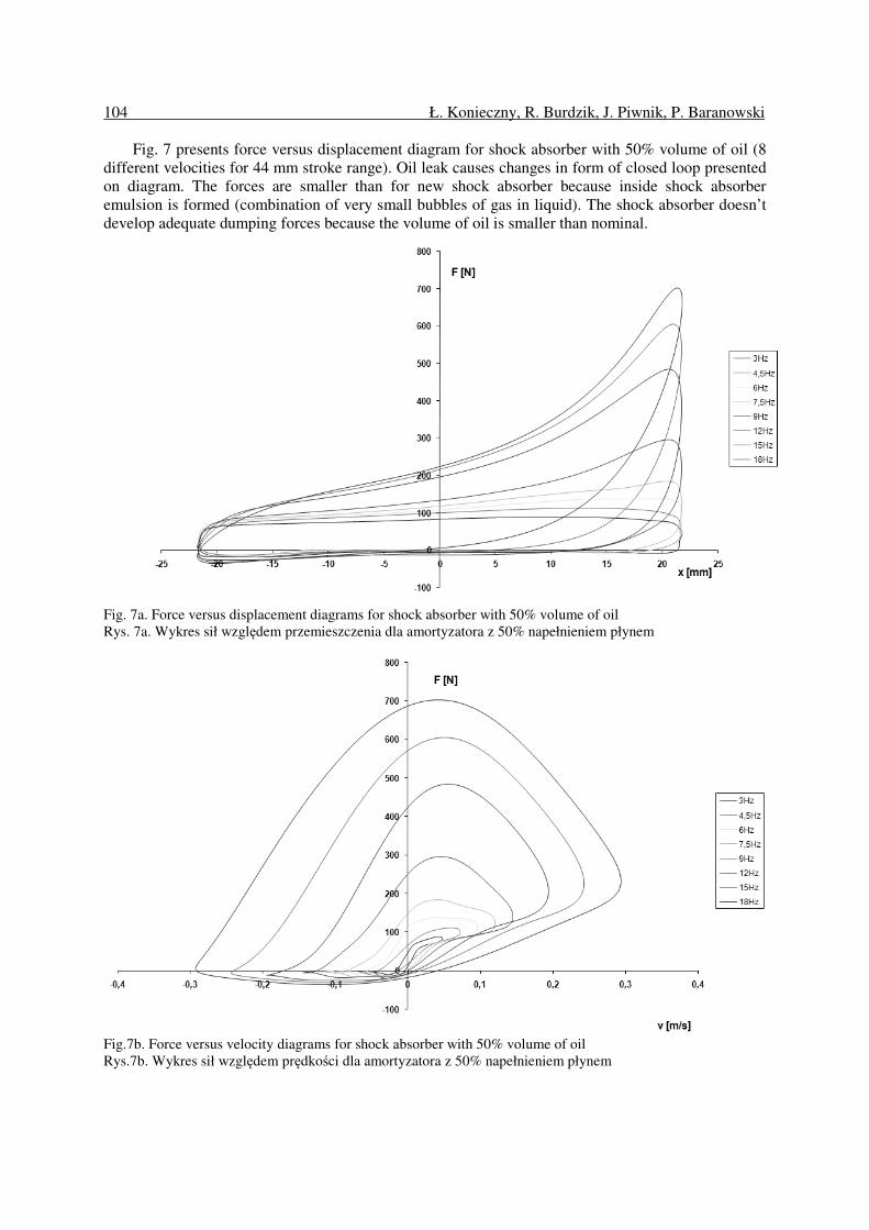
Fig. 7 presents force versus displacement diagram for shock absorber with 50% volume of oil (8
different velocities for 44 mm stroke range). Oil leak causes changes in form of closed loop presented
on diagram. The forces are smaller than for new shock absorber because inside shock absorber
emulsion is formed (combination of very small bubbles of gas in liquid). The shock absorber doesn’t
develop adequate dumping forces because the volume of oil is smaller than nominal.
Fig. 7a. Force versus displacement diagrams for shock absorber with 50% volume of oil
Rys. 7a. Wykres sił względem przemieszczenia dla amortyzatora z 50% napełnieniem płynem
Fig.7b. Force versus velocity diagrams for shock absorber with 50% volume of oil
Rys.7b. Wykres sił względem prędkości dla amortyzatora z 50% napełnieniem płynem

The influence of oil leak… 105
Fig. 8. Dumping characteristics for shock absorber with oil leak
Rys. 8. Charakterystyki tłumienia dla amortyzatora z ubytkiem płynu
Fig. 8 presents the influence of oil leak on dumping characteristics of shock absorber. The
difference of dumping forces for shock absorber above 70% volume of oil are similar (these are a little
different from each other – the differences for bound are greater). The small oil leak (to 70 % of oil in
shock absorber) does not change the dumping force because in twin tube shock absorber portion of oil
is in compensation chamber (the reserve for compensation of changing volume of oil caused by
moving piston rod). The greater oil leak (below 70 % volume of oil in shock absorber) causes essential
decrease of dumping force (the forces are several times lower).
5. SUMMARY
The dumping characteristic for new shock absorber is nonsymmetrical and nonlinear. For shock
absorber with 70% volume of oil the dumping forces are almost the same. The diagram determined of
force versus displacement (fig. 6) for shock absorber with oil leak corresponds to diagrams showed in
literature (fig. 4) The greater oil leak (below 70 % volume of oil in shock absorber) causes essentially
decrease of dumping force to smaller value. The result of this investigation can be used in simulation
researches of vehicle suspension dynamic.
References
1. Dixon J.C.: The shock absorber handbook. Society of Automotive Engineers, USA, 1999.
2. Gardulski J.: Bezstanowiskowa metoda oceny stanu technicznego zawieszeń samochodów
osobowych. Wydawinctwo Instytutu Technologii Eksploatacji, Radom, 2003.
3. Gardulski J.: Simulation studies of mechanical system with non-linear parameters of the structure
for operating construction needs. Machine Dynamics Problems. Vol. 23, No 3, 1999.
4. Gardulski J., Warczek J.: Moc tłumienia, jako parametr diagnostyczny amortyzatorów
samochodowych. Diagnostyka, nr 29, 2003, s. 69-72.

106 Ł. Konieczny, R. Burdzik, J. Piwnik, P. Baranowski
5. Konieczny Ł.: Badania amortyzatorów hydraulicznych na zmodyfikowanym stanowisku
indykatorowym. Zeszyty Naukowe Politechniki Śląskiej, s. Transport, z.61 Wydawnictwo
Politechniki Śląskiej, Gliwice, 2007, s.151-156.
6. Reipell J., Betzler J.: Podwozia samochodów – podstawy konstrukcji. WKiŁ, Warszawa, 2001.
7. Sikorski J.: Amortyzatory – budowa – badania – naprawa. WKiŁ, Warszawa, 1984.
Received 15.05.2009; accepted in revised form 16.12.2009