the impulse to your progress - hv technologies, inc catalog_0.pdf · your progress. faced with the...
TRANSCRIPT

pr
od
uc
t o
ve
rv
iew
The impulse to your progress

Faced with the technological complexity of today’s world,
you can achieve ambitious objectives with the support of
a new network of partners who are masters in their own fields.
Since its foundation in 1978, montena technology has gained a worldwide reputation for its leading-edge skills and competence in high voltage, high frequency and electromagnetic fields.
Montena technology masters design, development, manufacturing and installation of test and measurement equipment according to MIL Standards.
Our company is now considered a leader and number one supplier of simulators for NEMP effects. With many systems in service worldwide, the outstanding manufacturing quality and equipment reliability has been proven over the years.
Innovation, continuous improvement and partnership with experts enable us to provide our customers breakthrough technologies and turnkey solutions.
The multidisciplinary background of our highly qualified engineers and the flexibility of our structure make montena technology your ideal partner for transient pulse management.
montena technology sa
3
tAB
Le o
F c
oN
te
Nt
s
TABLE OF CONTENTs
TEsT AND MEAsUREMENT sYsTEMs Page
NEMP simulators MIL-STD-461 RS105 4 – 5
PCI test setup MIL-STD-188-125 6
SE & CWI test setup MIL-STD-188-125 7
Test setup MIL-STD-461 CS101, RS101 8
Test setup MIL-STD-461 CS106, CS114, CS115, CS116 9
ESD 300 kV test setup for helicopters MIL-STD-331C or NATO AECTP-250 10
UWB test setup 11
COMPONENTs & ACCEssORIEs
GENERATORs
NEMP Generators 12
Pulsed current injection (PCI) generators 13
MIL-STD CS106, CS114, CS115, CS116 14
GENERATORs ACCEssORIEs
Inductive and capacitive couplers
15
LISN and TPDs
Shielded Enclosure
High voltage coaxial loads
High voltage coaxial connectors and assemblies
ANTENNAs, LINEs
Radiating lines
16Impulse radiating antennas
TEM cells
Striplines, parallel plate lines
17E/H field generators
Helmholtz coils
PULsE MEAsUREMENT
Field sensors
18Ultra-fast voltage sensors
Passive integrators, impedance adapter
Software application for pulse measurement 19
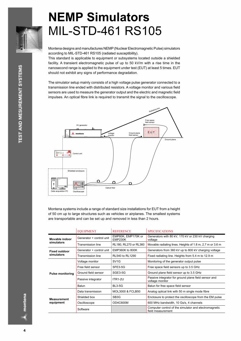
NEMP simulators MIL-STD-461 RS105 Montena designs and manufactures NEMP (Nuclear Electromagnetic Pulse) simulators according to MIL-STD-461 RS105 (radiated susceptibility).This standard is applicable to equipment or subsystems located outside a shielded facility. A transient electromagnetic pulse of up to 50 kV/m with a rise time in the nanosecond range is applied to the equipment under test (EUT) at least 5 times. EUT should not exhibit any signs of performance degradation.
The simulator setup mainly consists of a high voltage pulse generator connected to a transmission line ended with distributed resistors. A voltage monitor and various field sensors are used to measure the generator output and the electric and magnetic field impulses. An optical fibre link is required to transmit the signal to the oscilloscope.
Montena systems include a range of standard size installations for EUT from a height of 50 cm up to large structures such as vehicles or airplanes. The smallest systems are transportable and can be set up and removed in less than 2 hours.
EQUIPMENT REFERENCE SPECIFICATIONS
Movable indoor simulators
Generator + control unit EMP80K, EMP170K or EMP230K
Generators with 80 kV, 170 kV or 230 kV charging voltage
Transmission line RL180, RL270 or RL360 Movable radiating lines. Heights of 1.8 m, 2.7 m or 3.6 m
Fixed outdoor simulators
Generator + control unit EMP360K to 800K Generators from 360 kV up to 800 kV charging voltage
Transmission line RL540 to RL1290 Fixed radiating line. Heights from 5.4 m to 12.9 m
Pulse monitoring
Voltage monitor SV1G Monitoring of the generator output pulse
Free field sensor SFE3-5G Free space field sensors up to 3.5 GHz
Ground field sensor SGE3-5G Ground plane field sensor up to 3.5 GHz
Passive integrator ITR1-2U Passive integrator for ground plane field sensor and voltage monitor
Balun BL3-5G Balun for free space field sensor
Measurement equipment
Data transmission MOL3000 & FCLB50 Analog optical link with 50 m single mode fibre
Shielded box SB3G Enclosure to protect the oscilloscope from the EM pulse
Oscilloscope OD4C600M 600 MHz bandwidth, 10 Gs/s, 4 channels
Software Computer control of the simulator and electromagnetic field measurement
te
st
AN
d M
es
ur
eM
eN
t s
Ys
te
Ms
4

te
st
AN
d M
es
ur
eM
eN
t s
Ys
te
Ms
The following table gives some examples of simulators compliant with the 50 kV/m electric field required in MIL-STD-461 RS105.
GENERATOR REFERENCE
RADIATING LINE REFERENCE
EUT DIMENSION IN METER SYSTEM OVERALL DIMENSIONS IN METERWIDTH LENGTH HEIGHT WIDTH LENGTH HEIGHT
EMP80K-2-23 RL180-50 2.2 1.3 0.57 2.5 6.6 1.8
EMP170K-2-23 RL270-50 3.4 1.9 0.85 3.75 10.9 2.7
EMP230K-2-23 RL360-50 4.5 2.5 1.1 5.0 14.3 3.6
EMP360K-2-23 RL540-50 7.0 9.0 1.6 8.0 31.0 5.4
EMP450K-2-23 RL720-50 9.0 12.0 2.1 10.0 41.0 7.2
EMP670K-2-23 RL1080-50 13.0 18.0 3.2 15.0 62.0 10.8
EMP800K-2-23 RL1290-50 14.0 25.0 3.7 18.0 74.0 12.9
Rs105 simulators using GTEM and coaxial generators are available on request
RProven performance with many systems installed worldwideRTriangular transmission line design with distributed load resistors for bounded wave propagation with minimal reflexionRIndoor transportable small test systems; outdoor permanent large test installationsRAutomated management and test report generation for simple measurementRLow risk of operator’s handling mistakesROther pulse shapes according to other standards such as IEC or national standards on requestRExpertise in the refurbishment of existing old test installations
5
te
st
AN
d M
es
ur
eM
eN
t s
Ys
te
Ms
6
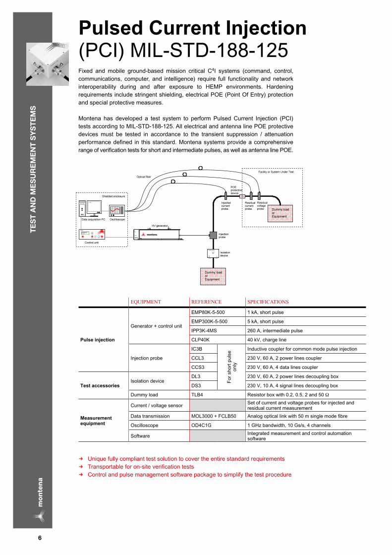
Pulsed Current Injection (PCI) MIL-STD-188-125 Fixed and mobile ground-based mission critical C4I systems (command, control, communications, computer, and intelligence) require full functionality and network interoperability during and after exposure to HEMP environments. Hardening requirements include stringent shielding, electrical POE (Point Of Entry) protection and special protective measures. Montena has developed a test system to perform Pulsed Current Injection (PCI) tests according to MIL-STD-188-125. All electrical and antenna line POE protective devices must be tested in accordance to the transient suppression / attenuation performance defined in this standard. Montena systems provide a comprehensive range of verification tests for short and intermediate pulses, as well as antenna line POE.
EQUIPMENT REFERENCE SPECIFICATIONS
Pulse injection
Generator + control unit
EMP80K-5-500 1 kA, short pulse
EMP300K-5-500 5 kA, short pulse
IPP3K-4MS 260 A, intermediate pulse
CLP40K 40 kV, charge line
Injection probe
IC3B
For
sho
rt p
ulse
on
ly
Inductive coupler for common mode pulse injection
CCL3 230 V, 60 A, 2 power lines coupler
CCS3 230 V, 60 A, 4 data lines coupler
Test accessoriesIsolation device
DL3 230 V, 60 A, 2 power lines decoupling box
DS3 230 V, 10 A, 4 signal lines decoupling box
Dummy load TLB4 Resistor box with 0.2, 0.5, 2 and 50 Ω
Measurement equipment
Current / voltage sensor Set of current and voltage probes for injected and residual current measurement
Data transmission MOL3000 + FCLB50 Analog optical link with 50 m single mode fibre
Oscilloscope OD4C1G 1 GHz bandwidth, 10 Gs/s, 4 channels
Software Integrated measurement and control automation software
RUnique fully compliant test solution to cover the entire standard requirementsRTransportable for on-site verification testsRControl and pulse management software package to simplify the test procedure

te
st
AN
d M
es
ur
eM
eN
t s
Ys
te
Ms
shielding Effectiveness (SE)
The purpose of the Shielding Effectiveness (SE) test is to demonstrate the compliance of a facility and apertures POE with the shielding performance required. Montena has developed a LabVIEW software application to simplify the shielding effectiveness assessment according to MIL-STD-188-125 test methods. The complete test setup is delivered with the software designed to drive a signal generator, amplifiers, a network analyser as well as RF-switches interconnecting the equipment.
RMeasurement automation with frequency sweeping and data collection RAutomatic switching between amplifiers and antennasRGeneration of measurement reportsRSoftware application can be used for IEEE Std 299 shielding effectiveness testsRDelivery and installation of complete test system
Continuous Wave Immersion (CWI)
Verification of small and mobile facilities is usually performed with the exposure of the system to a threat level EMP using a pulse simulator as presented on pages 4 and 5. But the verification of large or fixed facilities can only be performed with a low level illumination field in the frequency domain. It involves measuring the residual fields, charge/current densities and currents inside the facility while sweeping in the frequency domain on the whole EMP spectrum. It is then possible to assess the expected internal residual electromagnetic pulse due to the exposure to EMP by means of fast Fourrier transform and extrapolation. Montena supplies the entire test setup, including a LabVIEW software application.
RMeasurement automation with frequency sweeping and data collectionRAutomatic switching between amplifiers, antennas and sensorsRMeasurement chain compensation and post-processingRComputation of all pass-fail criteria according to the standard including the internal threat currentRReport and data file generationRDelivery and installation of complete test system
7

te
st
AN
d M
es
ur
eM
eN
t s
Ys
te
Ms
MIL-STD-461 CS101 and RS101MIL-STD-461 CS101 specifies the conducted susceptibility test of equipment and subsystem AC and DC input power leads, in the frequency range of 30 Hz to 150 kHz.
MIL-STD-461 RS101 is also used to assess the radiated susceptibility of equipment and subsystem enclosures, including electrical cable interfaces, in the frequency range of 30 Hz to 100 kHz.
Montena offers a complete test solution for both standards. A dedicated control software with a graphical user interface allows simple setup via scroll down menus to select the appropriate components. Calibration and measurement are designed to be fully automated, with reports generated afterwards.
EQUIPMENT REFERENCE SPECIFICATIONS
Frequency injection
Signal generator SIG10M 0 to 10 MHz
Power amplifier PA20K13A 0 to 300 kHz frequency range
Coupling transformers TR250K50A 50 A, for CS101
Radiating loop SG12-RS101 30 Hz to 100 kHz, 15 A continuous for RS 101
Test accessories
High power load VR15-210 Variable resistor to compensate the power current feedback into the amplifier
Precision resistor R0.5-200A 0.5 Ω 200 A, resistor for calibration
LISN LISN50-25 Line impedance stabilization network 50 µH, 20 A
Field monitoring sensor SCR4-RS101 Single coil for calibration
Measurement equipment
Current probe CT10000F 50 A, 1 Hz to 20 MHz
Oscilloscope OD2C100M 100 MHz bandwidth, 1 Gs/s, 2 channels
Software Management of calibration, settings, tests and reports
RAutomatic calibration for the full test frequency rangeRAutomatic configuration of the measurement equipment settingRBuilt-in scroll-down menus for selecting test equipment and componentsRFrequency sweepingRTest and calibration reports automatically generated
8

te
st
AN
d M
es
ur
eM
eN
t s
Ys
te
Ms
MIL-STD-461 CS106, 114, 115 and 116
CS106 is applicable to submarine and surface ship equipment and subsystem AC and DC input power leads. The generator delivers a transient pulse in the microsecond range, with repetition up to 20 pulses per second. CS114 is a swept bulk cable injection which simulates currents that will be developed on platform cabling from electromagnetic fields generated by antenna transmissions.CS115 uses a fast trapezoidal pulse to excite natural resonances associated with cables. The basic concern is to protect equipment from fast rise and fall time transients that may be present due to platform switching operations and external transient environments such as lightning and electromagnetic pulses.CS116 defines damped sinusoid transients at several fixed frequencies to simulate electrical current and voltage waveforms occurring in platforms from excitation of natural resonances.
Montena has developed a software controlled test bench covering all these test requirements. Thanks to a high frequency switching module, the calibration and measurement phases can be performed without changing any cabling of the test system. Montena proposes up to 17 frequencies for the CS116 test, enhancing the frequency coverage and test results.
EQUIPMENT REFERENCE SPECIFICATIONS
signal injection
Pulse generator PG-CS106 400V peak, 1.5 µs rise time, transient for CS106
Signal generator SIG1-2G 1.2 GHz, for CS114
Power amplifier PA400M150W 150 W, for CS114
Pulse generator for CS115 and CS116 POG-CS116+ M-CS115
Pulse generator with 6, 9, 17 frequencies for CS116 and module for CS115
Low frequency injection probe IC10M 10 kHz to 30 MHz, for CS106
High frequency injection probe IPDR250 10 kHz to 400 MHz, for CS114, 115 and 116
Test accessories
Coaxial dummy load PCL1G-400 50 Ω load for system calibration
Attenuators PATP20-100, PATP40-100 20 and 40 dB attenuators for system calibration
LISN LISN50-25 Line impedance stabilization network, 50 µH, 20 A
Measurement equipment
Current / voltage sensor Set of current and voltage probes
Oscilloscope OD2C600M 600 MHz bandwidth, 10 Gs/s, 2 channels
Software Automatic calibration, configuration, test and report
RSingle generator output for CS114, CS115 and CS116 tests allowing remote test automationRAutomatic calibration for each test and for the full test frequency rangeRAutomatic configuration of the measurement equipment settingsRBuilt-in scroll-down menus for selecting test equipment and componentsRTest and calibration reports automatically generated
9

te
st
AN
d M
es
ur
eM
eN
t s
Ys
te
Ms
EsD 300kV Test setup for HelicoptersMIL-STD-331 or NATO AECTP-250Helicopters and aircrafts can be electrically charged by flying through the air and by collisions with rain or snow. Additionally rain drops and snowflakes can also generate damage and disturbance known as precipitation static (P-static).
Montena has developed a system for electrostatic discharges up to 300 kV, to test personnel and helicopter borne electrostatic parameters according to MIL-STD-331C, MIL-STD-464A or NATO AECTP-250 leaflet 253. This test equipment simulates various parameters such as ESD from personnel to munitions, helicopter landing, in-flight refuelling and static precipitation. The equipment is built on two separate movable trolleys with the discharge electrode mounted on a piston which is adjustable in height and angle.
EQUIPMENT REFERENCE SPECIFICATIONS
EsD generator
Generator + control unit PGESD-300K-DP Output voltage ranging from 25 kV to 300 kV
Discharging electrode ESD-DE-300K 1m travel, 4 m high, ±60° tilt with pneumatic piston
Generator accessories
High voltage resistor ESD-R500-300K Optional 500 Ω discharge resistor
P-static adapter PST-50K Rod used with the precipitation test
Measurement equipment
Data transmission MOL3000 & FCLB50 Analog optical link with 50 m single mode fibre
Shielded box SB3G Enclosure to protect the oscilloscope from the EM pulse
Oscilloscope OD2C100M 100 MHz bandwidth, 1 Gs/s, 2 channels
Software Remote control of test equipment and measurement management
RMulti-purpose movable test equipment on separate trolleysRElectrode adjustable in height (from 1 to 4 meters) and angle ( ± 60°)RPositive and negative polarity availableROne system for ESD and P-static tests RPulse current measurementROptional 500 ohms discharge resistor RPossible charging of the EUT with the electrode groundedRComputer controlled or manual operation
10
Ultra Wide Band (UWB) Test setup
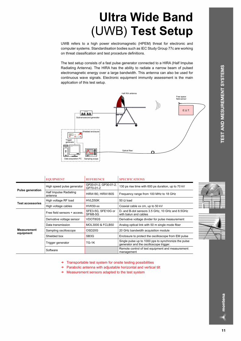
UWB refers to a high power electromagnetic (HPEM) threat for electronic and computer systems. Standardisation bodies such as IEC Study Group 77c are working on threat classification and test procedure definitions.
The test setup consists of a fast pulse generator connected to a HIRA (Half Impulse Radiating Antenna). The HIRA has the ability to radiate a narrow beam of pulsed electromagnetic energy over a large bandwidth. This antenna can also be used for continuous wave signals. Electronic equipment immunity assessment is the main application of this test setup.
EQUIPMENT REFERENCE SPECIFICATIONS
Pulse generationHigh speed pulse generator GP20-01-2, GP30-01-2,
GP70-01-2 130 ps rise time with 600 ps duration, up to 70 kV
Half Impulse Radiating antenna HIRA180, HIRA180S Frequency range from 100 MHz to 18 GHz
Test accessories High voltage RF load HVLD50K 50 Ω load
High voltage cables HVK50-xx Coaxial cable xx cm, up to 50 kV
Measurement equipment
Free field sensors + access. SFE3-5G, SFE10G or SFM8-5G
D- and B-dot sensors 3.5 GHz, 10 GHz and 8.5GHz with balun and cables
Derivative voltage sensor VDOT8GS Derivative voltage divider for pulse measurement
Data transmission MOL3000 & FCLB50 Analog optical link with 50 m single mode fiber
Sampling oscilloscope OSD20G 20 GHz bandwidth acquisition module
Shielded box SB3G Enclosure to protect the oscilloscope from EM pulse
Trigger generator TG-1K Single pulse up to 1000 pps to synchronize the pulse generator and the oscilloscope trigger.
Software Remote control of test equipment and measurement management
RTransportable test system for onsite testing possibilitiesRParabolic antenna with adjustable horizontal and vertical tiltRMeasurement sensors adapted to the test system
te
st
AN
d M
es
ur
eM
eN
t s
Ys
te
Ms
11

Ge
Ne
rA
to
rs
NEMP Generators Montena develops and manufactures high voltage pulse generators for NEMP (Nuclear Electromagnetic Pulse) tests according to MIL-STD-461 E/F.
These generators use direct capacitive circuits or Marx technology. Peaking circuits are often used to increase the impulse rise time.
All generators have a remote control unit providing indications and settings of the charging voltage, gas pressures and pulse triggering as well as an interlock switch for safety. USB and RS232 interfaces are available for control software applications.
Montena NEMP generators are designed to be connected to radiation lines such as bounded wave transmission lines or GTEM-cells.
REFERENCE
CHARGING VOLTAGE
WAVEFORM
LINE IMPEDANCE
REMARKS
EMP80K-2-23 80 kV
Double exponential
Rise time : 2.3 ± 0.5 ns
Duration time : 23 ± 5 ns
110 Ω
Direct discharge circuit
EMP170K-2-23 170 kV
Marx + peaking circuit
EMP230K-2-23 230 kV
EMP450K-2-23 450 kV
EMP670K-2-23 670 kV
EMP800K-2-23 800 kV
EMP80K-2-23-50 80 kV 50 Ω To be connected to a GTEM-cell
Generators for MIL-STD-461 version D are available upon request
R Technology and design scales up to a charging voltage of 1.2 MV R Interlock switch and automatic capacitor discharge for high safety requirementsR Compact and robust construction R Possible recycling of the SF6 gasR Proven performance and reliability with many generators installed worldwide
Montena design can be adapted to customers’ requirements to fulfil other standards, for other fields of application or for the refurbishment of existing NEMP test installations.
12

Ge
Ne
rA
to
rs
Pulsed Current Injection (PCI)
Generators Montena offers PCI generators for tests according to MIL-STD-188-125 1 / 2. Pulsed current injections (PCI) acceptance testing is used to demonstrate that electrical Point Of Entry (POE) protective devices perform in accordance with the transient suppression / attenuation requirements. The PCI tests require high energy generators for delivering current pulses either directly or through coupling devices in the cables.
The short pulse test is covered with two generators, EMP80K-5-500 for up to 1 kA pulse and EMP300K-5-500 for peak current pulses from 1 kA up to 5 kA. Additionally montena proposes a lower level pulse generator (EMP10K-5-500) for tests on electronic components.
The intermediate pulse test requires a generator delivering up to 260 A.
RF antenna line POE must be tested up to 400 A. Montena proposes a “charge line” generator for port testing, supplied with 9 different high voltage line lengths.
Each generator is fully configurable, with single and repetitive pulses, voltage adjustable output, manual or remote control.
REFERENCE
SHORT CIRCUIT CURRENT
CHARGING VOLTAGE
SPECIFICATIONS
EMP80K-5-500 1 kA 80 kVHigh current PCI short, rise time < 20ns, duration = 500 ns
EMP300K-5-500 1 kA to 5 kA 350 kV
IPP3K-4Ms 260 A 3 kV PCI intermediate pulse, rise time = 1 µs, duration = 4 ms
CPL40K 400 A 25 kV Charge line pulser, 50 Ω output
EMP10K-5-500 200 A 10 kV PCI short pulse for tests of electronic components
RTransportable, compact and robust generatorsRUnique set of test generators for MIL-STD-188-125 available on the marketRControl and data acquisition system available (calibration, data measurement and automatic report generation)
All designs can be adapted to the customer’s requirements, to fulfil other standards. Montena also supplies all accessories such as inductive, capacitive couplers, isola-tion devices, termination loads and automatic system monitoring, as shown on pages 6 and 7.
13

Ge
Ne
rA
to
rs
MIL-sTD Conducted susceptibility GeneratorsMontena develops and manufactures pulse generators for MIL standards conducted susceptibility tests, according to MIL-STD-461 CS106, CS114, CS115 and CS116 test methods.
For better frequency range coverage, montena CS116 generator is offered in 3 versions with respectively 6, 9 and 17 frequencies.
The following standalone generators are proposed :
REFERENCE SPECIFICATIONS STANDARDS
PG-Cs106 0 – 1 kV MIL-STD-461 F CS106
PG-Cs115 0 – 5 kV MIL-STD-461 D/E/F CS115
POG-Cs116-6 10, 100 kHz, 1, 10, 30, 100 MHz MIL-STD-461 CS116, 6 frequencies
POG-Cs116-9 10, 30, 100, 300 kHz, 1, 3, 10, 30, 100 MHz MIL-STD-461 CS116, 9 frequencies
POG-Cs116-17 10, 18, 30, 56, 100, 180, 300, 560 kHz 1, 1.8, 3, 5.6, 10, 18, 30, 56, 100 MHz MIL-STD-461 CS116, 17 frequencies
PG1275 125 V Imported and exported spikes and surges
Montena has designed the POG-CS116 pulse generator to host additional pulse modules for CS106, CS115 pulse delivery beside the built-in CS116 damped sinusoidal pulse modules. These factory installed modules and the CS116 modules are all connected to the same generator output. This allows the execution of all test frequencies and pulse shapes without re-cabling or module exchange need. The calibration as well as the measurement process is entirely automated. All settings and levels are recorded for measurement and test reports.
The POG-Cs116 generator can host following additional modules:
REFERENCE CHARGING VOLTAGE REMARKS
M-Cs106 0 – 1 kV Module CS106 to be plugged in POG-CS chassis
M-Cs115 0 – 5 kV Module CS115 to be plugged in POG-CS chassis
R Control software for fully automated test setup and measurement R CS116 generator with up to 17 test frequencies for more accurate susceptibility assessment R One single output for the POG-CS116 (all CS116 test frequencies and additional modules) R Modular approach for all budgetsR Complete set of accessories for test and measurement available (probes, loads, etc..) R All generators can be ordered such as table top or 19” rack mounting versions
All designs can be adapted to the customer’s requirements, to fulfil other standards.
14

Inductive and Capacitive CouplersInductive and capacitive couplers are intended for currents injection on signals or mains supply cables.
REFERENCE MAX CURRENT MAX VOLTAGE NUMBER OF LINES REMARKS
CCL3
5 kA peak 80 kV
2 lines, mains Capacitive couplers designed for MIL-STD-188-125, short pulseCCs3 4 lines, signals
Ds3 4 lines, signals Decoupling box to be used with CCS3
DL3 2 lines, mains Decoupling box to be used with CCL3
IC3B Bundle Ø100 mm maxInductive coupler for common mode injection of MIL-STD-188-125, short pulse
IPDR250 100 W permanent / 500 W 15 min. Bundle Ø44 mm max Injection probe for MIL-STD 461 CS114, CS115 or CS116 tests
CJDR250 Calibration jig for injection probe IPDR250
IC10M 600 V Injection probe for MIL-STD 461 CS106 or RTCA DO160 section 17
LIsN and TPDsMontena proposes high current LISN according to MIL STD specifications. TPDs (terminal protection devices) are a combination of a LISN with additional filters to protect the power supply network.
REFERENCE REMARKS
LIsN50-25 LISN for MIL-STD, 1 phase, 50 µH, 25 A
LIsN50-500 LISN for MIL-STD, 1 phase, 50 µH, 500 A
LIsN50-1000 LISN for MIL-STD, 1 phase, 50 µH, 1000 A
TPD50-100 LISN with TPD for MIL-STD 461 D/E/F, 50 µH, 100 A including 20 m shielded cable
shielded Enclosure This shielded box is meant to protect the measurement equipment during EM pulse tests.
REFERENCE REMARKS
sB3G Shielded box, 0 to 3 GHz with 230 V power filter and coaxial feedthrough connectors
High Voltage Coaxial LoadsThese high voltage coaxial loads are especially designed for high voltage pulses.
REFERENCE MAXIMUM VOLTAGE REMARKS
HVLD50K 75 kV (1 ns pulse)High voltage 50 Ω coaxial load
HVLD200K 200 kV (1 ns pulse)
TBL4 30 kV Cable termination load for MIL-STD-188-125 : 0.2 / 0.5 / 2 / 50 Ω
HV Coaxial Connectors & Assemblies Montena proposes high voltage/high frequency 50 ohms coaxial cables with proprietary connectors, specifically developed for fast high voltage pulse transmission.
REFERENCE
TYPE
IMPEDANCE
PULSE MAX. VOLTAGE
FREQUENCY RANGE
REMARKS
HVM50K-a¹ Connector
50 Ω
75 kV, < 1 ns DC – 4 GHz¹: a is connector male and socket female
HVK50-x²-y3 Assembly 3: y, connectors HVM50K, N, open end
HVM200K-a Connector200 kV, < 1 ns DC – 1.6 GHz
¹: a is connector male and socket female
HVK200-x²-y3 Assembly 3: y, connectors HVM50K, N, open end
²: x is the length in cm. Available cable lengths : 50, 100 and 200 cm
Ge
Ne
rA
to
rs
A
cc
es
so
rie
s
15

AN
TE
NN
As
, LIN
Es
Radiating Lines Radiating lines are to be connected with high voltage pulse generators, for MIL-STD-461 RS105 test method.
REFERENCE LINE HEIGHT LINE LENGTH EUT MAX HEIGHT REMARKS
RL180-50 1.8 m 6.6 m 0.57 m
MIL-STD-461 E/F RS105
RL270-50 2.7 m 10.9 m 0.85 m
RL360-50 3.6 m 14.3 m 1.1 m
RL540-50 5.4 m 31 m 1.6 m
RL720-50 7.2 m 41 m 2.1 m
RL1080-50 10.8 m 62 m 3.2 m
RL1290-50 12.9 m 74 m 3.7 m
Impulse Radiating AntennasImpulse Radiating Antenna (IRA) is a special type of antenna designed to radiate ultra wideband (UWB) electromagnetic field signals. Montena proposes Half Impulse Radiating antennas (HIRA).
REFERENCE
DIAMETER
FREQUENCY RANGE
MAX INPUT VOLTAGE
REMARKS
HIRA 1801.8 m 100 MHz –
18 GHz
20 kV 50 Ω high voltage connector and impedance adapter for the antennaHIRA 180s 75 kV
Customized versions can be proposed on request.
TEM CellsOpen TEM cells are tri-plate cells designed for small objects immunity testing and field probes calibration.
REFERENCE
PLATE HEIGHT
FREQUENCY RANGE
MAXIMUM FIELD
REMARKS
TEM220 33 cm 0 to 220 MHz 800 V/m
Open TEM cellsTEM500 14.7 cm 0 to 500 MHz 1 kV/m
TEM1000 7.4 cm 0 to 1 GHz 2.6 kV/m
TEM3000 2.5 cm 0 to 3 GHz 5.6 kV/m
16

AN
TE
NN
As
, LIN
Es
striplines / Parallel Plate Lines
Stiplines and parallel plate lines suited for small and medium size objects immunity testing.
REFERENCE
FREQUENCY RANGE
SEPTUM HEIGHT
INPUT POWER
IMPEDANCE
REMARKS
sR50-1000
0 to 1 GHz
15 cm 1 kW 50 ΩStripline according to ISO 11452-5sR90-1000 15 cm 200 W 90 Ω
sR50-1000-20 20 cm 200 W 50 Ω
sRA5090 100 W Impedance adapter 50 Ω to 90 Ω
PPL200-70s 10 kHz – 30 MHz 70 cm 500 W 50 Ω Parallel plate line for immunity test to vertical and horizontal EM fieldsPPL200 10 kHz – 30 MHz 106 cm 500 W 50 Ω
E / H Field GeneratorsE/H generators are designed for immunity test to electromagnetic fields on medium size devices such as automotive vehicles and broadcast receivers.
REFERENCE FREQUENCY RANGE HEIGHT MAX POWER
GENE-H-15-1K
10 kHz – 30 MHz
1.5 – 2.5 m1 kW
GENE-H-15-3K 3 kW
GENE-H-30-1K2.5 – 3.5 m
1 kW
GENE-H-30-3K 3 kW
Helmholtz Coils Helmoltz coils are used to generate precise low frequency magnetic fields.
REFERENCE DIAMETER COIL FACTOR FIELD IN THE CENTRE (1 MIN) REMARKS
HC300 300 cm 7.5 A/m /A 430 A/m 5.4 G Coils mounted on 2 trolleys for SAE J551-17
HC100 100 cm 15.6 A/m /A 940 A/m 11.8 G IEC-61000-4-8 / -10
HC30 30 cm 117 A/m /A 4’700 A/m 59 G IEC-61000-4-8 / -10
HC11 11 cm 1’250 A/m /A 25’000 A/m 310 G Multi-directional support, especially designed for the watch industry
sC65 6.5 cm 4’800 A/m /A 290’000 A/m 3’644 G Very high field coil
sC100 10 cm 4’600 A/m /A 230’000 A/m 2’870 G Very high field coil and cooling fan
17

PU
Ls
E M
EA
sU
RE
ME
NT
Field sensorsMontena designs and manufactures derivative electromagnetic field sensors for fast pulse measurement. Sets of D-dot (electric field) and B-dot (magnetic field) sensors are available. Sensors are passive devices – no power supply is required. Montena provides accessories to complete the measurement chain, such as baluns, passive integrators, specific coaxial cables and optical fibre link.
Ground plane field sensors
REFERENCE
TYPE
RISE TIME
FREQUENCY RESPONSE
EQUIVALENT AREA
sGE1G D-dot (electric) 320 ps 1 GHz 1 x 10⁻² m²
sGE3-5G D-dot (electric) 110 ps 3.5 GHz 1 x 10⁻³ m²
sGE10G D-dot (electric) 32 ps 10 GHz 1 x 10⁻⁴ m²
sGM2G B-dot (magnetic) 160 ps 2.0 GHz 1.32 x 10⁻⁴ m²
Free space field sensors
REFERENCE
TYPE
RISE TIME
FREQUENCY RESPONSE
EQUIVALENT AREA
sFE1G D-dot (electric) 320 ps 1.0 GHz 2 x 10⁻² m²
sFE3-5G D-dot (electric) 110 ps 3.5 GHz 2 x 10⁻³ m²
sFE10G D-dot (electric) 32 ps 10 GHz 2 x 10⁻³ m²
sFM2G B-dot (magnetic) 160 ps 2.0 GHz 2.65 x 10⁻⁴ m²
Ultra-fast Voltage sensorThe ultra-fast derivative voltage dividers are used to measure high voltage fast pulse signals into a coaxial cable. They can be inserted in the measurement chain with minimal insertion loss.
REFERENCE
TYPE
RISE TIME
FREQUENCY RESPONSE
MAX VOLTAGE MEASUREMENT
CONNECTORS
VDOT8G V-dot (voltage) 50 ps 7.5 GHz 20 kV for 1 ns pulse Coaxial 7/16
VDOT8Gs V-dot (voltage) 120 ps 3.0 GHz 75 kV for 1 ns pulse Coaxial HVM50K
Passive Integrators, Impedance AdapterPassive integrators are used to compensate the derivative behaviour of the B-dot, D-dot electromagnetic field and voltage sensors. They have 1 megohm output impedance and should be directly connected to the oscilloscope high impedance input. The impedance adapter converts the signal of high impedance systems to 50 Ω equipment, such as remote measurement of voltage probe using a 50 Ω fiber optic link.
REFERENCE
TIME CONSTANT
FREQUENCY LIMIT
IN / OUT IMPEDANCE
CONNECTORS
ITR1-2U 1.2 µs 1.0 GHz50 Ω / 1 MΩ N input
BNC outputITR12U 12 µs 150 MHz
IA1M50 650 MHz 1 MΩ + 100 kΩ / 50 Ω BNC inputs SMA output
18

PU
Ls
E M
EA
sU
RE
ME
NT
software Application for Pulse
MeasurementThe monitoring of high intensity fast electromagnetic pulses requires specific measurement competencies. Montena has developed software applications to simplify the measurement of the following type of pulses:- Fast high intensity electromagnetic pulses from derivative field sensors- Fast high voltage pulse from derivative voltage dividers- Current transformers.
The proposed software package includes for instance the following measurement equipment:
Once all equipment involved in the measurement chain has been introduced, the software application is able to automatically control the digital oscilloscope and process the read values to display the measured E-field, B-field or voltage pulses in their respective units.
RUniversal software for various types of sensors and pulse measurement capabilitiesRAutomatic management of the oscilloscopeRIncludes all factors for the sensors, attenuators, fibre optic link, etc. RCompatible with most available digital oscilloscopes.RUser-friendly - handling error free.
19
montena technology saroute de montena 891728 RossensSwitzerland
Tel : +41 26 411 84 84Fax : +41 26 411 17 79
Your local representative
NE
MP
fiel
d te
st s
imul
atio
nw
ww
.pol
ygon
e.ch