the impact toughness and hardness of treated and untreated
TRANSCRIPT
Research ArticleThe Impact Toughness and Hardness of Treated and UntreatedSisal Fibre-Epoxy Resin Composites
Wilson Webo ,1 Leonard Masu ,1 and Maina Maringa 2
1Department of Mechanical Engineering, Faculty of Engineering and Technology, Vaal University of Technology,Private Bag X021, Andries Potgieter Blvd., Vanderbijlpark 1911, South Africa2Department of Mechanical and Mechatronics Engineering, Faculty of Engineering and Technology,Central University of Technology, Private Bag X20539, Bloemfontein 9300, South Africa
Correspondence should be addressed to Wilson Webo; [email protected]; Leonard Masu; [email protected]; andMaina Maringa; [email protected]
Received 25 February 2018; Revised 23 May 2018; Accepted 27 June 2018; Published 1 August 2018
Academic Editor: Yuanshi Li
Copyright © 2018WilsonWebo et al. -is is an open access article distributed under the Creative Commons Attribution License,which permits unrestricted use, distribution, and reproduction in any medium, provided the original work is properly cited.
-e effect of the combined chemical treatment of sisal fibres through the subsequent processes of mercerisation (alkali treatment),then silane treatment and eventually acid hydrolysis, on sisal fibre was investigated. -e effect of the treated fibres on the impacttoughness and hardness of their composites with epoxy resin was also studied. Scanning electron microscopy of the surfaces of thetreated and untreated fibres showed that the chemical treatment processes enhanced the removal of surface impurities andtherefore increased the roughness of the surfaces of the fibres. -is avails an increased surface area for interlocking with matrixand is, therefore, expected to enhance adhesion of the two. -e treated fibre reinforced composites were observed to have highervalues of impact toughness and hardness than the untreated fibre reinforced composites. -ese higher values were attributed tobetter interfacial bonding due to better mechanical interlocking between the treated fibres and epoxy resin arising from theincreased roughness of the treated fibres.
1. Introduction
A composite material is a physical mixture of two or moredifferent materials that result in a component with superiorproperties to those of any individual component [1]. Incontrast to metallic alloys, each material retains its separatechemical, physical, andmechanical properties [1, 2].-emainadvantages of composite materials are their high specificstrength and stiffness, when compared with other materialsallowing for a reduction in weight of finished parts [3].
-e constituents of a composite are categorized as thereinforcement and the matrix. -e reinforcement is thediscontinuous phase while the matrix is the continuousphase [1–3]. -e reinforcement is usually embedded in thematrix. -e reinforcement is usually in the form of fibres,sheets, or particles whereas the matrix is either a polymer,ceramic, or metal [2]. -e reinforcement provides strengthand stiffness to the composite material [4].-ematrix on theother hand transfers and distributes the applied loads to the
fibres and in many cases contributes some needed propertiessuch as ductility, toughness, and electrical insulation [1, 3].Examples of polymer matrices include epoxy resins, polyesterresins, and phenolic resins while metallic matrices includealuminium resin, magnesium resin, and titanium resin [3].-emost common methods used in the manufacture of compositematerials are compression moulding, pultrusion, hand layup,resin transfer moulding (RTM), injection moulding, and fil-ament moulding [1].
Composites may be classified as particulate reinforcedcomposites or fibre reinforced composites [3]. -e partic-ulate reinforced composites consist of tiny particles havingthickness in the micron [5, 6] and nanoscales [7] embeddedinto a matrix. -e particles occur in the form of flakes orpowder [8]. Fibre reinforced composites on the other handare made of continuous or discontinuous fibres that areembedded in a matrix [3].
A reemerging area of fibre reinforced composites is that ofnatural fibre reinforced composites [9]. Natural fibres are
HindawiAdvances in Materials Science and EngineeringVolume 2018, Article ID 8234106, 10 pageshttps://doi.org/10.1155/2018/8234106

increasingly being considered as an environmentally friendlysubstitute for synthetic fibres in the reinforcement ofpolymer-based composites [2, 9]. -e use of these fibres in-stead of glass and carbon is, for example, under considerationin the automotive industry [10]. Althoughmany different typesof natural fibres are available, sisal (Agave sisalana) is a par-ticularly attractive option due to its rapid growth over a widerange of climatic conditions [11] and its low cost [10]. Al-though the use of natural fibres partly satisfies the requirementsof regulations that enforce the use of environmentally friendlyand sustainable materials [10], the matrix system must also beconsidered in this regard. Clearly, completely biodegradablematrices such as polylactic acid (PLA) are preferable, but thecurrent high cost of these matrices is a disadvantage incomparison to epoxy resin [10]. Sisal/epoxy composites aretherefore of considerable commercial interest.
Even though natural fibres have the potential to supplementglass fibres in polymer composites [12], limitations arise withrespect to mechanical performance and moisture absorptionwhen natural fibres are used [9]. -ese limitations are presentirrespective of whether thermoset or thermoplastic polymersare used as the matrix material. Previous studies [13–15] havereported that the main factor that limits the mechanicalproperties of natural fibre composites is the chemical in-compatibility between the hydrophilic lignocellulosic moleculesof the natural fibre and the hydrophobic molecule of the resin.-is incompatibility leads to difficulties in ensuring effectivefibre-matrix interface bonding which, in turn, causes ineffectiveload transfer between the reinforcing material and the matrix[10, 12, 13]. Various options, including chemical treatments ofnatural fibres and the use of compatibilisers, have been sug-gested in order to achieve the necessary compatibility of surfaceenergies between the fibres and the matrix. Li et al. [16] pre-sented a review article on the various chemical treatments usedto improve compatibility between natural fibres and polymermatrices. Approaches such as mercerisation (alkali treatment),silane treatment, acetylation, benzoylation, use of maleatedcoupling agents, peroxide treatment, permanganate treatment,and isocyanate treatment were considered. Amongst the var-ious methods presented, mercerisation and silane treatmentshave been widely reported on.
Mercerisation involves immersing the fibres in an alkalinesolution for a period of time. It works by increasing the surfaceroughness of the fibre which improves mechanical bondingwith matrices [16]. It also exposes more cellulose on the surfaceof the fibre to potential chemical bonding with matrices [17].Silane treatment entails soaking the fibres in a weak solution ofa silane diluted in water/alcohol or water/ketonemixture. In thepresence of water, silane breaks down into silanol and alcohol.-e silanol reacts with the OH groups of the cellulose in naturalfibres, forming stable covalent bonds on the cell wall that arechemisorbed onto the fibre surface [16]. Use of silane improvesthe degree of cross-linking in the interface region and increasesthe fibre surface area, allowing for stronger bonding between thefibre and matrix [18]. Acid hydrolysis involves subjectingnatural fibres to harsh acid treatment, which causes theamorphous lignin regions to break up thus releasing the in-dividual crystallites of cellulose. Sulphuric acid and hydrochloricacid are extensively used in performing acid hydrolysis [19].
While most researchers have used either alkali treatmentor silane treatment or acid hydrolysis individually, it isnecessary to attempt using the three methods of treatment incombination, since the mechanisms by which they affectnatural fibres are completely different. Herrera-Franco andValadez-Gonzalez [20] considered high-density poly-ethylene [HDPE] reinforced with henequen fibres at a vol-ume fraction of 20%. -e effects of alkali and silanetreatments on these fibres were studied individually in ad-dition to the effect of the two treatments acting in combi-nation. It was found that alkali treatment resulted intoalmost no improvement, whereas silane resulted into a 19%improvement. When the combination of the treatment wasconsidered, there was an improvement of 30%.
Impact tests are usually carried out during the earlieststages of the design process in order to determine the in-tegrity of the material under impact loading. Impact tests areusually done in order to determine the maximum impactload that a material can bear at a particular temperature [21].Impact resistance of fibre-reinforced composites, like that ofother materials, is measured by several test methods, namely,Charpy, Izod, drop weight, split Hopkinson bar (SHB),explosive, and ballistic impact [22]. -e results of impacttests are presented in the form of fracture energy, damageaccumulation, and/or measurement of the number of dropsto achieve a determined damage or stress level. -e resultsdepend on many variables such as size of specimen, strainrate, type of instrumentation, and test setup [22].
Wang et al. [23] identified two different damagemechanisms for fibre reinforced composites that wereloaded on a drop weight impact system. For fibre fractionslower than the critical fibre volume, fibre fracture dominatedthe failure mechanisms, while for higher values than thecritical fibre volume, the fibre pull-out mechanism domi-nated the response.
Ramires and Frollini [24] used the Izod unnotchedimpact test to investigate the impact properties of sisal fibrereinforced tannin-phenolic composites. -ey carried outtheir investigations according to the ASTM D256 standard.-e researchers found that the improvement in the in-terfacial bond was the main reason for the improvement ofthe impact strength. -e authors reported that the increasedacid sites at the surface of the sisal fibres improved interfacialadhesion. -e researchers further reported that the Izodimpact strength of the composites increased with an increasein the fibre content up to a maximum of 50% fibre content.However, beyond 50% fibre content, the Izod impactstrength decreased due to ineffective impregnation of resinin the fibres. -e researchers concluded that the use of sisalfibres as reinforcement material in tannin-phenolic resinwas useful since it greatly improved the impact properties ofthe composite.
Han-Seung et al. [25] carried out a study on the effect ofdifferent compatibilising agents on the tensile strength andIzod impact strength of lignocellulosic materials. Low- andhigh-density polyethylene was used as the matrix, while ricehusk flour and wood flour were used as reinforcement.Maleated propylene and maleated polyethylene were used ascompatibilising agents to improve the fibre-matrix adhesion.
2 Advances in Materials Science and Engineering
-e researchers found that maleated polyethylene improvedthe Izod impact strength of notched specimens because of theenhancement in the fibre-matrix interfacial adhesion. On theother hand, the Izod impact strengths of composites producedfrom maleated polypropylene reinforced with rice huskdropped slightly. -e researchers concluded that the Izodimpact strength of the maleated polyethylene-incorporatedcomposites improved slightly because of a better interfacialbonding between the matrix and the fibre.
Hardness refers to the resistance a solid shows to localdeformation. A hard indenter is placed onto the surface ofa material and is then pressed into the material. -e size ofthe permanent indentation thus formed is then measured todetermine the hardness of the material. -e commonmethods used to measure hardness are the Brinell hardnesstest, Rockwell hardness test, Vickers hardness test, and theBarcol hardness test. While Brinell, Rockwell, and Vickershardness test methods are commonly used, the Barcolhardness test is rarely performed.
Kumar et al. [26] studied the hardness of treated anduntreated samples reinforced with sisal/glass epoxy-basedhybrid composites using Rockwell hardness testingmachine.In each case, five samples were tested and the average valuewas tabulated. Test specimens were made according to theASTMD 785 test standard.-e diameter of the ball indenterused was 0.25 inches, and all the readings were taken 10seconds after the indenter made firm contact with thespecimen. All the sample surfaces were rubbed with smoothemery paper, which facilitates accurate reading. It was ob-served that 2 cm fibre length composites had a higherhardness than 1 cm and 3 cm fibre length composites.
-e effects of three combined chemical treatments,namely, mercerisation, silane treatment and acid hydrolysis,on sisal fibres are investigated in this paper. -e effect ofthese combined treatments on the impact toughness andhardness of their composites with epoxy resin is also lookedinto. -is is in contrast to other studies on impact andhardness that have used these treatments individually. -ecomposites were manufactured using the vacuum infusionmethod of composite manufacture. -is method preventsthe entry of air into, and, formation of voids in the com-posites that are fabricated and is expected to facilitate theattainment of high strength and stiffness of the compositesproduced. Furthermore, this method differs from the otherfabrication techniques by virtue of the fact that the creationof a vacuum in the mould cavity ensures that the resin isdriven into the mould and through the laid out fibres [27] byatmospheric pressure and therefore ensures proper wettingof reinforcing fibres. Air bubbles can still be introduced intothe system through the mixing process of the resin andhardener prior to charging into the mould, and throughmould leaks. -ese, however, are weaknesses that areameliorated in the infusion process.
2. Experimental Details
2.1. Materials. Epoxy Epolam 2015 resin and Epolam 2014hardener were obtained from AMTcomposites of South Africa.-emix ratio of the resin and the hardener according to the data
sheet obtained from the company was 100 : 32. Sisal fibres ina bundle of 10kgs were obtained from Mogotio farm, NakuruCounty, Republic of Kenya.-e reagents whichwere used in thiswork were: sodium hydroxide, 3-glycidyloxypropyltrimethoxy-silane, methanol, and hydrochloric acid (HCL). Sodium hy-droxide was provided by Minema chemicals (Pty) limited while3-glycidyloxypropyltrimethoxy-silane, methanol, and hydro-chloric acid were provided by Sigma Aldrich limited, all fromSouth Africa.
2.2. Preparation of Treated Sisal Fibres. -e sisal fibres weremercerised by immersion in 5% sodium hydroxide solutionfor 20 hours. -e fibres were then washed with distilled waterin order to remove the sodium hydroxide from them and thenfurther immersed in 1% acetic acid in order to neutralise anyremaining sodium hydroxide. -e fibres were, thereafter,immersed in a silane solutionmade up of 5% of 3 glycidyloxy-propyl-trimethoxy-silane diluted in a 95% aqueous solution ofmethanol, the later in order to hydrolyse the silane and makeit active [16]. -is treatment was then followed by immersionof the fibres in a 67.5% solution of hydrochloric acid for 1hour [28]. -e treated fibres were, thereafter, washed withdeionized water and dried in an oven at 45°C for 24 hours.
2.3. Manufacture of Composites. -e vacuum infusionmethod of manufacturing composites was used to fabricate thecomposites here as shown in Figure 1. -is method supportsproper wetting of the reinforcing fibres, which gives rise tobetter and stronger interfacial bonding of the fibre and matrix.Both treated and untreated sisal fibre-epoxy resin compositeswere manufactured using this method. -e sisal fibres were cutusing a pair of scissors and straightened using a comb in orderto avoid bunching of fibres which would otherwise minimisewetting of the fibreswith resin and, therefore, reduce the efficacyof reinforcement. -e fibres were then weighed using anelectronic balance with an accuracy of ± 0.5 gm and groupedinto various masses corresponding to different fibre weight
Vacuum bag
Resin trap
Vacuumpump
Resin inlet
Figure 1: -e vacuum infusion process.
Advances in Materials Science and Engineering 3
fractions. A thin layer of wax was smeared onto the base ofa square glass mould of 50 cm by 50 cm. -e wax ensures thatthe composite can be easily removed from the glass mould aftercuring. Predetermined weights of sisal fibres were spreadlongitudinally in the glass mould. -e fibres were then coveredwith peel ply and infusion mesh simultaneously. -e peel plywas made of polyester material and is used to wick away slightexcesses of resin. -e infusion mesh was made of a plasticmaterial, and it aids the resin to flow efficiently throughout thefibres. A bleeder cloth was then laid near the tube exit to thevacuum so that excess resin could be sucked through the tube tothe resin trap. Spiral tubings were then both connected, one tothe tube from the resin beaker and one to the vacuum.-ereafter, a vacuum bag was used to cover the entire casting. Atacky tape was then used to secure the vacuum bag onto themould.-e vacuumpumpmotorwas switched on, and the tubeleading to the resin storage container was temporarily closed offusing a G-clamp in order to avoid suction of air into the fibresbefore creating a vacuum.A break of one hour was allowedwiththe vacuum pump running as the resin was being prepared.-eresin and the hardener were thenmeasured in their appropriateratios using an electronic balance of accuracy ±0.5 gm andsubsequently mixed using a spatula. Air entrapment in the resinwas eliminated through puncturing of air bubbles with a sharpneedle. After the break, the resin suction pipe was placed intothe resin container and the closing G-clamp on the pipe wasremoved in order to allow suction of the resin onto the fibres.-e sisal fibre reinforced epoxy resin composites were sub-sequently cured in air for 24 hours. After this air curing, thecompositewas further cured in an oven at 80°C for four hours asrecommended by the supplier in order to produce compositeswith excellent mechanical properties. -e reinforcement wasvaried from 0 to 50 wt.%, inclusive in the different composites.
2.4. Impact Tests. In order to determine the fracturetoughness of the fabricated composites, Charpy impact testswere performed at room temperature using a HounsfieldBalanced Impact Tester (Tensometer Ltd., Croydon, En-gland). -e Hounsfield Balanced Impact Tester imposesa three-point impact similar to that created by the Charpyapparatus specified in ASTMD6110-10. Test specimens witha geometry of 50×12× 5mm in length, width, and thickness,respectively, were cut from the cast composites using a CNCmachine. For each composition, a V-notch of 45°± 1°, rootradius of 0.25± 0.05mm, and notch width of 2mm wasmade. -e specimens were, thereafter, sanded off usingemery cloth of grade 220 in order to ensure that no out-of-plane notches were introduced onto the specimens. -eCharpy impact test, also known as the Charpy V-notch test,is a standardised high-strain rate test which is used to de-termine the amount of energy absorbed by a material duringfracture. -e results obtained from Charpy impact test area measure of a given material’s toughness and can also beused to determine temperature-dependent brittle-ductiletransition curve of a material [3]. When determining thefracture toughness using the Charpy impact test frame, thesample piece is loaded horizontally onto the apparatus, andthe Charpy impact test pendulum hammer is released to
strike the notched sample on the back side of the V-notch.-e notch is introduced in the test samples to create a knownpoint of stress concentration at which cracks are expected toinitiate. After impact, the sample is removed and its failuresurfaces examined. If the failure surface is flat and smooth,then failure is classified as brittle. If on the contrary, thefailure surface is fibrous, then failure is classified as ductile.-e scope of the current study was restricted to the de-termination of the impact toughness of the composites atroom temperature.
2.5. Hardness. Hardness testing was done in accordancewith ASTM D 2583 test standard specifications using theBarber Colman Barcol Impressor. Test specimens witha geometry of 12.7×12.7× 3mm in length, width, andthickness, respectively, were cut from the cast compositesusing a CNC machine. -e hardness test characterises theindentation hardness of materials by measuring the depth ofpenetration of the indenter point. -e Barcol Impressor,model GYZJ-934-1 consists of a hardened steel truncatedcone, with an angle of 26° and a flat tip of 0.157mm diameterat the spring loading plunger, which is used to make in-dentation on materials.
2.6. Scanning Electron Microscopy. -e surface morphol-ogies of the composites of various fibre weight fractions forboth treated and untreated composites were analysed usingelectron microscopy technique.-e composite surfaces wereanalysed using the Zeiss Environmental SEM (ESEM: modelEVO HD 15, operating at 20 kV), where the specimen wasgold sputter coated using Quorum 150R ES model thin filmcoating equipment. -e coating was applied in order toenable the specimens to become easily visible. -e treatedand untreated sisal fibres were scanned as well.
3. Results and Discussion
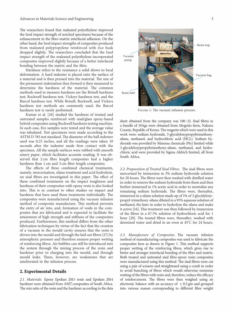
3.1. SEM Results of Untreated and Treated Sisal Fibres.
20 μm Mag = 700×WD = 27.5 mm
EHT = 3.00 kVPa 1
Pa 1 = 286.6 μm
Pa R1
Pb 1 = 89.3°
Signal A = SE1Date: 4 Apr 2017Chamber = 1.56e – 003 Pa
Figure 2: Untreated sisal fibre.
4 Advances in Materials Science and Engineering

-e untreated and treated sisal fibres were subjected toscanning electron microscopy with the resulting imagesshown in Figures 2 and 3.
From the images, it is clear that the cross-sectional di-mensions of the treated sisal fibres (180.3 μm) are smallerthan that of the untreated sisal fibres (286.6 μm). A reductionin size of the treated sisal fibres leads to better mechanicalproperties of the resulting composites than those of theuntreated sisal fibres due to an increase in number ofreinforcing fibres (and therefore reinforcing fibre volumefraction) that can be packed in a cross section of a matrix.
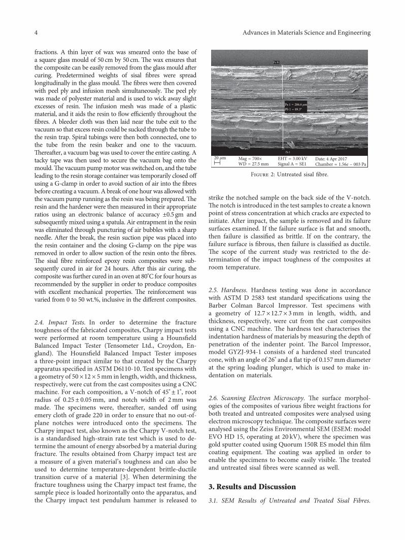
3.2. Impact Test Results. -e impact fracture surfaces wereobserved with a scanning electron microscope. Five scanswere conducted for each sample, and representative mi-crographs are shown in Figures 4(a)–4(j) and 5.
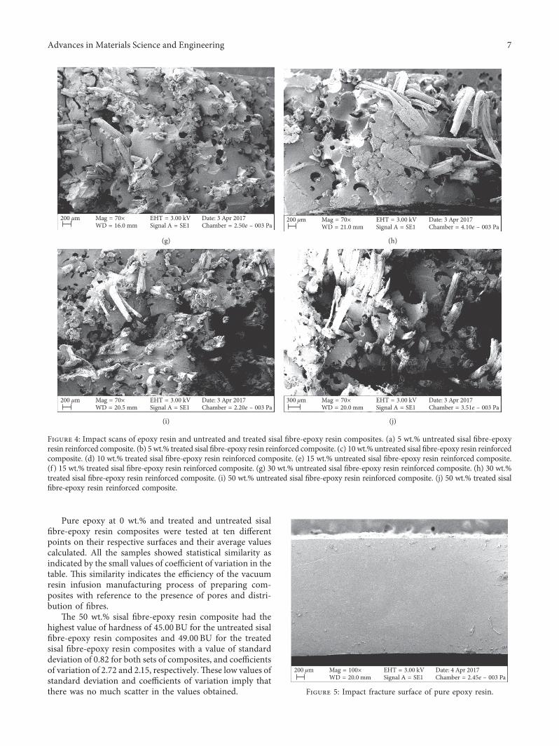
When both the untreated and treated composites werecompared at each weight fraction and the number of in-cidences of fibre pull-out counted in each case, it was foundthat there were higher incidences of fibre pull-out in theuntreated sisal fibre-epoxy resin composites than in the treatedsisal fibre-epoxy resin composites. Furthermore, the impactfracture surface of the epoxy resin exhibited a smooth fracturesurface. Higher incidence of fibre pull-out is a clear indicationof lower fibre-matrix adhesion. Lower interfacial adhesionresults in the matrix absorbing higher fractions of the totalenergy imposed on a composite than would be the case wherehigher interfacial adhesion exists and, therefore, leads to lowervalues of impact energy, where the fracture toughness of thematrix is lower.
Average values of impact toughness for both the treatedsisal fibre-epoxy resin composites and the untreated sisalfibre-epoxy resin composites which were determined usinga Charpy impact test machine are presented in Table 1. -eimpact toughness of the pure epoxy resin was also de-termined and is recorded in the table as well.
-e results in Table 1 clearly show that impact energyof reinforced composites was enhanced by the threecombined treatment methods for the reinforcing fibres.Increase of impact energy due to an enhanced fibre-matrix
adhesion was also reported by Ramires and Frollini [24].-e average impact energy of the treated sisal fibre-epoxyresin composites is seen in the table to have increased by28.09%, 20.07%, 14.06%, 15.44%, and 22.34% for com-posites with 5 wt.%, 10 wt.%, 15 wt.%, 30 wt.%, and 50 wt.%, respectively, over the values obtained for the untreatedsisal fibre-epoxy resin composites for the same weightfractions. -e standard deviations of the impact energiesfor both the treated and the untreated composites aresmall, all falling within the range from 0.12 to 0.93, whilethe coefficient of variations for both the treated and un-treated sisal fibre-epoxy resin composites are also low,ranging from 13.48% to 31.59%. -e low values of thestandard deviations and coefficient of variations impliesthat there was not much scatter in the experimental dataobtained.
It is evident from the values in the above table that theaverage values of impact energy of the tested specimensincreased from a value of 0.84 joules for pure epoxy resin toa maximum of 10.34 joules and 12.65 joules for a 50 wt.%untreated and treated sisal fibre-epoxy resin composites,respectively. -ese are 1130.95% and 1405.95% increases inthe value of impact energy, respectively, over the values ofpure epoxy resin. -e increase of the average impact energyfor the untreated and treated fibre reinforced compositesover the values for the pure epoxy resin for the five per-centage weights of 5 wt.%, 10 wt.%, 15 wt.%, 30 wt.%, and 50wt.% were significant at 35.73%, 197.62%, 313.10%, 678.57%,and 1130.95% and 154.76%, 252.38%, 371.43%, 798.81% and1405.95%, respectively, for the untreated and treated sisalfibre-epoxy resin composites. -e higher values of impactenergy for the treated sisal fibre-epoxy resin composites overthe untreated sisal fibre-epoxy resin composites can be at-tributed to the improved mechanical interlocking due torougher surfaces of the treated sisal fibres and improvedinterfacial bonding.
-e values of impact toughness shown in Table 1 areplotted in Figure 6.
-e curve plots in Figure 6, for both the treated anduntreated sisal fibre-epoxy resin composites depict a con-tinuous increase of the impact toughness with an increase infibre loading. -e magnitude of the impact energy of theplotted curve for the treated sisal fibre-epoxy resin com-posites is higher than that for the untreated sisal fibre-epoxyresin composites. -is difference in magnitude of the twocurves is because of the difference in reinforcing effects of thetreated and untreated sisal fibre. In addition, both curves donot have minimum points. -e absence of minimum pointsin both curves is because the range of percentage weights atwhich tests were done did not include those at or around theminimum point.-e correlation coefficient in both graphs isvery unity, implying a near perfect curve fit of the curves tothe experimental data plotted in both case.
3.3. Hardness Test Results. -e results arising from themeasurements of hardness are presented in Table 2 forthe treated and untreated sisal fibre-epoxy resin composites.-e results at 0 wt.% represent pure epoxy resin.
20 μm Mag = 700×WD = 27.0 mm
EHT = 3.00 kV
Pa 1
Pa 1 = 180.3 μm
Pa R1
Pb 1 = 89.0°
Signal A = SE1Date: 4 Apr 2017Chamber = 1.75e – 003 Pa
Figure 3: Treated sisal fibres.
Advances in Materials Science and Engineering 5

20 μm Mag = 1.00 K×WD = 23.0 mm
EHT = 3.00 kVSignal A = SE1
Date: 3 Apr 2017Chamber = 2.72e – 003 Pa
(a)
20 μm Mag = 1.00 K×WD = 18.0 mm
EHT = 3.00 kVSignal A = SE1
Date: 3 Apr 2017Chamber = 1.79e – 003 Pa
(b)
100 μm Mag = 200×WD = 20.5 mm
EHT = 3.00 kVSignal A = SE1
Date: 3 Apr 2017Chamber = 2.15e – 003 Pa
(c)
100 μm Mag = 200×WD = 20.0 mm
EHT = 3.00 kVSignal A = SE1
Date: 3 Apr 2017Chamber = 3.39e – 003 Pa
(d)
100 μm Mag = 200×WD = 18.0 mm
EHT = 3.00 kVSignal A = SE1
Date: 3 Apr 2017Chamber = 1.92e – 003 Pa
(e)
100 μm Mag = 200×WD = 16.5 mm
EHT = 3.00 kVSignal A = SE1
Date: 3 Apr 2017Chamber = 2.86e – 003 Pa
(f )
Figure 4: Continued.
6 Advances in Materials Science and Engineering
Pure epoxy at 0 wt.% and treated and untreated sisalfibre-epoxy resin composites were tested at ten differentpoints on their respective surfaces and their average valuescalculated. All the samples showed statistical similarity asindicated by the small values of coefficient of variation in thetable. -is similarity indicates the efficiency of the vacuumresin infusion manufacturing process of preparing com-posites with reference to the presence of pores and distri-bution of fibres.
-e 50 wt.% sisal fibre-epoxy resin composite had thehighest value of hardness of 45.00 BU for the untreated sisalfibre-epoxy resin composites and 49.00 BU for the treatedsisal fibre-epoxy resin composites with a value of standarddeviation of 0.82 for both sets of composites, and coefficientsof variation of 2.72 and 2.15, respectively.-ese low values ofstandard deviation and coefficients of variation imply thatthere was no much scatter in the values obtained.
200 μm Mag = 70×WD = 16.0 mm
EHT = 3.00 kVSignal A = SE1
Date: 3 Apr 2017Chamber = 2.50e – 003 Pa
(g)
200 μm Mag = 70×WD = 21.0 mm
EHT = 3.00 kVSignal A = SE1
Date: 3 Apr 2017Chamber = 4.10e – 003 Pa
(h)
200 μm Mag = 70×WD = 20.5 mm
EHT = 3.00 kVSignal A = SE1
Date: 3 Apr 2017Chamber = 2.20e – 003 Pa
(i)
300 μm Mag = 70×WD = 20.0 mm
EHT = 3.00 kVSignal A = SE1
Date: 3 Apr 2017Chamber = 3.51e – 003 Pa
(j)
Figure 4: Impact scans of epoxy resin and untreated and treated sisal fibre-epoxy resin composites. (a) 5 wt.% untreated sisal fibre-epoxyresin reinforced composite. (b) 5 wt.% treated sisal fibre-epoxy resin reinforced composite. (c) 10 wt.% untreated sisal fibre-epoxy resin reinforcedcomposite. (d) 10 wt.% treated sisal fibre-epoxy resin reinforced composite. (e) 15 wt.% untreated sisal fibre-epoxy resin reinforced composite.(f ) 15 wt.% treated sisal fibre-epoxy resin reinforced composite. (g) 30 wt.% untreated sisal fibre-epoxy resin reinforced composite. (h) 30 wt.%treated sisal fibre-epoxy resin reinforced composite. (i) 50 wt.% untreated sisal fibre-epoxy resin reinforced composite. (j) 50 wt.% treated sisalfibre-epoxy resin reinforced composite.
200 μm Mag = 100×WD = 20.0 mm
EHT = 3.00 kVSignal A = SE1
Date: 4 Apr 2017Chamber = 2.45e – 003 Pa
Figure 5: Impact fracture surface of pure epoxy resin.
Advances in Materials Science and Engineering 7

-e values of hardness presented in Table 2 are plotted inFigure 7.
From Figure 7, it is clear that there is an initial increase inthe values of hardness of the treated and untreated sisalfibre-epoxy resin composites up to maximum values of 30and 38 BU respectively, both at a reinforcing fibre weight of10% fibre. After this, the values of hardness reduce down toa value of 29 BU at a reinforcing fibre weight of 15%, which ishigher that the value of 26 BU for pure epoxy resin.-ereafter, the values of hardness increase continuouslyupto a reinforcing fibre weight of 50%. -e reduction in theBarcol hardness after 10 wt.% can be attributed to the poorwettability between the fibres and the matrix leading to
agglomeration as the fibre weight percentage increases upto15 wt.%. From 15 wt.%, the values of hardness increasescontinuously upto 50 wt.% due to more even distribution ofthe reinforcing fibres and a corresponding increase in thestiffness of the composites. -e correlation coefficient inboth graphs is near unity, implying a near perfect curve fit tothe experimental data plotted in both cases.
3.4.Comparison toOtherPublishedWorks. It is interesting tocompare the current results with the previous works. Table 3summarises the available impact and hardness properties ofpolymeric composites based on natural fibres.
Table 1: Values of impact toughness for pure epoxy as well as treated and untreated sisal fibre-epoxy resin composites.
Weight % of thereinforcing fibre
Impact energy of untreated sisal fibre-epoxyresin composites
Impact energy of treated sisal fibre-epoxyresin composites % increase of
impact energyRange (joules) Average (joules) Coefficient of
variation (%)Range(joules)
Average(joules)
Coefficient ofvariation
Epoxy (0) 0.54–1.22 0.84± 0.24 28.33 0.54–1.22 0.84± 0.24 28.33 —5 0.81–1.89 1.14± 0.29 25.47 1.63–2.44 2.14± 0.29 13.48 28.0910 2.30–2.71 2.50± 0.12 14.86 1.08–4.75 2.96± 0.93 31.59 20.0715 1.36–4.61 3.47± 0.86 24.81 2.03–5.56 3.96± 0.84 21.32 14.0630 5.28–7.86 6.54± 0.67 22.45 6.34–8.15 7.55± 0.67 25.47 15.4450 8.76–11.74 10.34± 0.74 18.44 10.77–13.15 12.65± 0.82 25.22 22.34
I = 0.0001w2 + 0.1903w + 0.5684R2 = 0.9965
I = 0.0007w2 + 0.1969w + 0.9397R2 = 0.9994
0
2
4
6
8
10
12
14
0 10 20 30 40 50 60
Impa
ct en
ergy
(jou
les)
Fibre weight fraction (%)
Untreated sisal fibre-epoxy resin compositesTreated sisal fibre-epoxy resin composites
Figure 6: A plot of the average values of impact energy versus fibre weight fraction % for treated and untreated sisal fibre-epoxy resinreinforced composites.
Table 2: Barcol values of hardness for pure epoxy resin and treated and untreated sisal fibre-epoxy resin composites.
Weight % of thereinforcing fibre
Values of hardness for the untreated sisal fibre-epoxyresin composites (Barcol units-BU)
Values of hardness for the treated sisal fibre-epoxyresin composites (Barcol units-BU)
Range (BU) Average (BU) Coefficient ofvariation (%) Range (BU) Average (BU) Coefficient of
variation (%)Epoxy (0) 25.00–27.00 26.00± 0.94 3.63 25.00–27.00 26.00± 0.94 3.635 27.00–31.00 29.00± 1.41 4.88 29.00–31.00 30.00± 0.94 3.1410 29.00–31.00 30.00± 0.82 2.72 37.00–39.00 38.00± 0.82 2.1515 27.00–31.00 29.00± 1.49 5.14 27.00–31.00 29.00± 1.56 5.3930 38.00–41.00 39.00± 1.77 3.46 42.00–46.00 43.00± 1.43 3.5450 44.00–47.00 45.00± 1.65 4.35 48.00–51.00 49.00± 1.32 3.26
8 Advances in Materials Science and Engineering

It is evident from Table 3 that the current results are animprovement of 7%–56% for impact and 9% for hardness onthe values obtained from the previous results. Clearly, thecombined chemical treatment of mercerisation, silane, andacid hydrolysis, leads to an improvement in the mechanicalproperties of impact and hardness of the order of 7%–56%for impact and 9% for hardness of sisal fibre reinforcedepoxy resin composite.
4. Conclusions
-e following conclusions were made:
(1) Chemical treatment of sisal fibre surfaces leads tocontinuous increases in the impact toughness of thetreated sisal fibre-epoxy resin composites with in-creasing weight fraction of the reinforcing fibres.
(2) Chemical treatment of sisal fibre surfaces leads to anincrease in the hardness of the sisal fibre-epoxy resincomposites.
(3) -e hardness of both the treated and untreated sisalfibre-epoxy resin composites increased gradually withan increase in fibre loading up to a maximum fibreweight fraction of 10% and then decreased beyondhere up to fibre weight content of 15% as a result offibre bunching, thereafter increasing gradually up tofibre weight fraction of 50% due to an increase in the
spatial distribution of the reinforcing fibre and in-crease in the stiffness of the resulting composite.
(4) -e combined chemical treatment of mercerisation,silane, and acid hydrolysis leads to an improvementin the mechanical properties of impact and hardnessthat is higher than in cases where only one treatmentprocess is used on its own.
Conflicts of Interest
-e authors have no conflicts of interest to disclose in re-lation to the current research.
Acknowledgments
-e research was supported by Vaal University of Tech-nology, South Africa.
References
[1] G. Jin and M. C. Jeffrey, “Polylactic acid composites in-corporating casein functionalized cellulose nanowhiskers,”Journal of Biological Engineering, vol. 7, no. 1, p. 31, 2013.
[2] R. A. V. Prasad and K. M. Rao, “Mechanical properties ofnatural fibre reinforced polyester composites: jowar, sisal andbamboo,” Materials and Design, vol. 32, no. 8-9, pp. 4658–4663, 2011.
B = 0.0005w2+ 0.3592w + 26.077R2 = 0.9596
B = –0.0022w2 + 0.5527w + 27.087 R2 = 0.8303
0
10
20
30
40
50
60
0 10 20 30 40 50 60
Barc
ol h
ardn
ess (
BU)
Fibre weight fraction (%)
Untreated sisal fibre-epoxy resin compositesTreated sisal fibre-epoxy resin composites
Figure 7: A plot of average values of the Barcol hardness (BU) versus fibre weight fraction % for treated and untreated sisal fibre-epoxyresin composites.
Table 3: A summary of impact strength and hardness of selected natural fibre composites.
Matrix Fibre (type oforientation)
Fibre content(%) Type of treatment Impact strength
(joules)Hardness
(Barcol units) Reference
PLA Sisal (random) 30.00 None 3.30 — [29]PLA/PEG-plasticized Sisal 30.00 None 4.50 — [29]
UFR Sisal (random) 50.00 Alkali, MAPP 9.50 — [30]PP Wood (flour) 30.00 Alkali, MAPP 5.00 — [30]PP/EPR/MAPP Wood (flour) 30.00 Alkali, MAPP 7.00 — [30]PP/MAPP Wood (flour) 30.00 Alkali, MAPP 5.00 — [30]Epoxy Areca fibre 40.00 Alkali — 45.00 [31]
Epoxy Sisal(unidirectional) 0.00–50.00 Alkali, silane, acid hydrolysis 0.84–12.65 26.00–49.00 Present study
Advances in Materials Science and Engineering 9
[3] M. Sakthivei and S. Ramesh, “Mechanical properties ofnatural fibre (banana, coir, sisal) polymer composites,” Sci-ence Park, vol. 1, no. 1, pp. 1–6, 2013.
[4] F. C. Campbell, Introduction to Composite Materials, ASMInternational, Materials Park, OH, USA, 2010.
[5] M. Maringa and C. G. Injairu, “A study of the elastic behaviorof some natural materials under applied bending loads,”Journal of Civil Engineering and Practice, vol. 7, no. 1,pp. 13–46, 2010.
[6] S. Y. Fu, X. Q. Feng, B. Lauke, and Y. W. Mai, “Effect ofparticle size, particle-matrix adhesion and particle loading onmechanical properties of particulate-polymer composites,”Composites Part B: Engineering, vol. 39, no. 6, pp. 933–961,2012.
[7] R. Kaundal, P. Amar, and B. Sandhyarani, “Effect of red mudand copper slag particles on physical and mechanical prop-erties of bamboo-fibre-reinforced epoxy composites,” Journalof Advances in Mechanical Engineering, vol. 4, article 141248,2012.
[8] N. Chawla and Y. Shen, “Mechanical behavior of particlereinforced metal matrix composites,” Journal of AdvancedEngineering Materials, vol. 3, no. 6, pp. 357–370, 2001.
[9] D. M. Panaitescu, N. F. Adriana, G. Marius, I. S. Catalin,R. Constantin, and D. I. Michaela, “Properties of polymercomposites with cellulose microfibrils,” in Advances inComposite Materials, pp. 103–122, National Institute of Re-search and Development in Chemistry and Petrochemistry,Bucharest, Romania, 2013.
[10] A. K. Mohanty, M. Misra, and L. T. Drzal, “Surface modi-fication of natural fibres and performance of the resulting biocomposites: an overview,” Composite Interfaces, vol. 8, no. 5,pp. 313–343, 2001.
[11] K. Joseph, S. Vaeghese, G. Kalaprasad, S. -omas,L. Prassanakumar, and P. Koshy, “Influence of interfacialadhesion on the mechanical properties and fracture behaviorof short sisal fibre reinforced polymer composites,” EuropeanPolymer Journal, vol. 32, no. 10, pp. 1243–1250, 1996.
[12] S. Raghavendra, P. Lingaraju, S. Balachandra, and P.G.Mukunda,“Mechanical properties of short banana fibre reinforced naturalrubber composites,” International Journal of Innovative Researchin Science, Engineering and Technology, vol. 2, no. 5, pp. 1652–1655, 2013.
[13] C. Giuseppe, A. Latteri, R. Giuseppe, and C. Gianluca,“Composites based on natural fibre fabrics,” in Woven FabricEngineering, pp. 317–342, University of Catania, Catania,Italy, 2008.
[14] S. Rassman, “Effects of processing conditions on the me-chanical and water absorption properties of resin transfermoulded kenaf fibre reinforced polyester composite lami-nates,” Composite Part A: Applied Science and Manufacturing,vol. 41, no. 11, pp. 1612–1619, 2010.
[15] H. N. Dhakal, Z. Y. Zhang, and M. O. W. Richardson, “Effectof water absorption on the mechanical properties of hempfibre reinforced unsaturated polyester,” Advanced Polymerand Composites, vol. 67, no. 7-8, pp. 1674–1683, 2007.
[16] X. Li, G. Lope, and P. Satyanarayan, “Chemical treatments ofnatural fibre for use in natural fibre-reinforced composites:a review,” Composite Part A, vol. 15, no. 1, pp. 25–33, 2007.
[17] N. Mokaloba and R. Batane, “-e effects of mercerization andacetylation treatments on the properties of sisal fibre and itsinterfacial adhesion characteristics on polypropylene,” In-ternational Journal of Engineering, Science and Technology,vol. 6, no. 4, pp. 83–97, 2014.
[18] J. Andersons and K. Tillman, “Strength and adhesion char-acteristics of elementary flax fibres with different surfacetreatment,” Applied Science Manufacturing, vol. 34, no. 7,pp. 603–612, 2001.
[19] E. T. N. Bisanda and M. P. Ansell, “-e effect of silanetreatment on the mechanical and physical properties ofcomposites,” Journal of Composite Science and Technology,vol. 41, no. 2, pp. 165–178, 1991.
[20] P. J. Herrera-Franco and A. Valadez-Gonzalez, “A study of themechanical properties of short natural-fiber reinforcedcomposites,” Composites Part B: Engineering, vol. 36, no. 8,pp. 597–608, 2005.
[21] M. D. Joshua, “Impact testing of advanced composites,”Journal of Advanced Topics in Characterization of Composites,vol. 65, no. 5, pp. 97–112, 2008.
[22] F. A. Silva, N. Chawla, and R. D. Toledo Filho, “An experi-mental investigation of the fatigue behaviour of sisal fibres,”Journal of Material Science and Engineering A, vol. 516,no. 1-2, pp. 90–95, 2009.
[23] B. Wang, S. Panigrahi, L. Tabil, and W. Crerar, “Pretreatmentof flax fibres for use in rotationally moulded biocomposites,”Journal of Reinforced Plastics and Composites, vol. 26, no. 5,pp. 447–463, 2007.
[24] E. C. Ramires and E. Frollini, “Tannin-phenolic resins: syn-thesis, characterization and application in bio based com-posites reinforced with sisal fibres,” Composites Part B:Engineering, vol. 43, no. 7, pp. 2836–2842, 2012.
[25] Y. Han-Seung,M. P.Walcott, S. K. Hee-sookim, and K. Hyun-joong, “Effect of different compatibilizing agents on themechanical properties of lignocellulosic material filled poly-ethylene bio composites,” Journal of Composite Structures,vol. 79, no. 3, pp. 369–375, 2007.
[26] M. A. Kumar, G. R. Reddy, Y. S. B. Naidu, and V. N. P. Naidu,“Frictional co-efficient, hardness, impact strength andchemical resistance of reinforced sisal glass fibre epoxy hybridcomposites,” Journal of Composite Materials, vol. 44, no. 26,pp. 3195–3202, 2010.
[27] A. H. Saputra and G. Setyarso, “Vacuum infusion equipmentdesign and the influence of reinforcement layers addition tothe resin infusion time,” Journal of Polymers, vol. 162, no. 1,pp. 1–6, 2017.
[28] S. Beck-candanedo, M. Roman, and D. G. Gray, “Effect ofreaction conditions on the properties and behavior of woodcellulose nanocrystal suspensions,” Journal of Bio-Macro-molecules, vol. 6, no. 2, pp. 1048–1054, 2005.
[29] M. K. Gupta and R. K. Srivastava, “Properties of sisal fibrereinforced epoxy composites,” Indian Journal of Fibre andTextile Research, vol. 41, pp. 235–241, 2016.
[30] G. Keledi, A. Sudar, C. Burgstaller, K. Renner, andB. Pukanszky, “Tensile and impact properties of three-component PP/wood/elastomer composites,” Express Poly-mer Letters, vol. 6, no. 3, pp. 224–226, 2012.
[31] C. V. Srinivasa and K. N. Bharath, “Impact and hardnessproperties of areca fibre-epoxy reinforced composites,”Journal of Material Environmental Science, vol. 2, no. 4,pp. 351–356, 2011.
10 Advances in Materials Science and Engineering

CorrosionInternational Journal of
Hindawiwww.hindawi.com Volume 2018
Advances in
Materials Science and EngineeringHindawiwww.hindawi.com Volume 2018
Hindawiwww.hindawi.com Volume 2018
Journal of
Chemistry
Analytical ChemistryInternational Journal of
Hindawiwww.hindawi.com Volume 2018
Scienti�caHindawiwww.hindawi.com Volume 2018
Polymer ScienceInternational Journal of
Hindawiwww.hindawi.com Volume 2018
Hindawiwww.hindawi.com Volume 2018
Advances in Condensed Matter Physics
Hindawiwww.hindawi.com Volume 2018
International Journal of
BiomaterialsHindawiwww.hindawi.com
Journal ofEngineeringVolume 2018
Applied ChemistryJournal of
Hindawiwww.hindawi.com Volume 2018
NanotechnologyHindawiwww.hindawi.com Volume 2018
Journal of
Hindawiwww.hindawi.com Volume 2018
High Energy PhysicsAdvances in
Hindawi Publishing Corporation http://www.hindawi.com Volume 2013Hindawiwww.hindawi.com
The Scientific World Journal
Volume 2018
TribologyAdvances in
Hindawiwww.hindawi.com Volume 2018
Hindawiwww.hindawi.com Volume 2018
ChemistryAdvances in
Hindawiwww.hindawi.com Volume 2018
Advances inPhysical Chemistry
Hindawiwww.hindawi.com Volume 2018
BioMed Research InternationalMaterials
Journal of
Hindawiwww.hindawi.com Volume 2018
Na
nom
ate
ria
ls
Hindawiwww.hindawi.com Volume 2018
Journal ofNanomaterials
Submit your manuscripts atwww.hindawi.com