the impact of smart inverters - nrel
TRANSCRIPT

The Impact of Smart Inverters:
How Rule and Regulation Will Transform DG into Smart Systems
John Berdner

Presentation Overview
Acknowledgements Attached to Integrated Smart Inverter Functions • Improved grid stability • Voltage regulation
Monitoring and Distributed Control • Provides insight into grid below the substation • Makes DER adaptable
Valuation Methodologies • Below the Substation
Next Steps
2

Acknowledgments
• This presentation gives an overview of the Status of Advanced inverter functionality and the CA Rule 21 requirements and related UL 1741 / IEEE 1547 requirements under development. • The summaries provided herein are based on the work
done to date by the California Smart Inverter Working Group (SIWG), Sandia, Hawaiian Electric Inc. and theUL 1741 / IEEE 1547 Working Groups for ride through, anti-islanding, and real and reactive power control. • This work is part of an evolving consensus based
activity involving utilities and inverter industrymembers of the Smart Inverter Working Group andthose participating in the UL 1741 / IEEE 1547 revision process. – PLEASE PARTICIPATE!
3
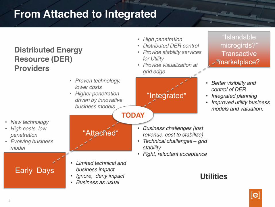
From Attached to Integrated
Early Days
“Attached”
“Integrated”
“Islandable microgirds?” Transactive
marketplace?
Distributed EnergyResource (DER) Providers
Utilities
• New technology • High costs, low
penetration• Evolving business
model
• Proven technology,lower costs • Higher penetration
driven by innovative business models
• High penetration • Distributed DER control • Provide stability services
for Utility • Provide visualization at
grid edge
• Limited technical and business impact • Ignore, deny impact • Business as usual
• Business challenges (lostrevenue, cost to stabilize) • Technical challenges – grid
stability • Flght, reluctant acceptance
• Better visibility and control of DER • Integrated planning • Improved utility business
models and valuation. TODAY
4

The Old Days (2000 - 2003)
• Grid tied PV systems were rare • General philosophy was: • Produce unity power factor • Get out of the way quickly if anything bad happened • Tight trip limits • No requirements for ride through
• Relevant Standards • UL 1741, IEEE 1547, 1547.1
5

Today (2014 - 2016)
• CA rule 21 approves smart inverter functionality. Phase 1 autonomous behaviors (Dec 2015) • Voltage and frequency ride through • Real and reactive power control • Return to service behaviors / ramp rate control
• Hawaiian Electric Inc. implements mandatory ride through requirements (Jan 2015) • CA rule 21 Phase 2 in development. Bi-directional
communication standards for inverters (TBD) • Relevant Standards • UL 1741 IEEE 1547, 1547.a,1547.1 • IEC 61850, IEEE 2030.5 • UL 1998 (firmware certification)
6

New Regulatory Concepts (in the US)
• Voltage and frequency ride through • Must not trip requirements during abnormal excursions
• Real and reactive power control • Provides frequency stability and voltage regulation
• Operating regions with differing behaviors • Multiple areas are bounded by pair points of
Voltage/time or frequency/time
• Cease to energize (momentary cessation) • A mode where the DER must cease to energize the
area EPS but must not trip. • Return to service • The criteria and behaviors required as the DER re-
energizes the area EPS following an excursion 7

CA Rule 21 - Status
• The CPUC issued a final ruling on Phase 1 requirements on 18 December, 2014. • The three IOU’s filed tariffs with the PUC in January 2015
• Revised Rule 21 Phase 1 is now in effect • Permissive upon publication of Supplement A in UL 1741. • Becoming mandatory upon the latter of: 31 Dec 2015 or;
12 months after the publication of Supplement A in UL 1741
• Phase 2 discussions on communications are underway • Ability to update and verify settings of DER remotely • Initially envisioned as periodic set it and forget it
(autonomous operation) • Near real time control envisioned for larger systems
8

CA Rule 21 – Status (cont)
• Phase 2 is moving toward consensus on data Models and Protocols • IEC 61850 data model • SEP 2, IEEE 2030.5 protocol
• Still debating which entities/devices communicate with each other • Direct utility communications of DER units seems
unlikely except for very large DER units • Direct utility communications to facilities level for large
plants • Indirect communication to distributed DER through an
abstraction layer seems like best model • Utilities, ISO’s, Muni’s, Co-ops • Manufacturers, System integrators, third party aggregators
9

Communications Example – Hawaii Settings
• On Oahu PV Generation is approximately 250 MW on a1200 MW grid. • In aggregate, PV is single largest generation unit.
• Hawaiian Electric (HECO) experienced two frequencyevents in last 18 months on Oahu • Modeling suggested changes were needed to voltage
and frequency ride through • HECO worked with inverter industry to develop a two
stage implementation plan • Interim settings based on existing UL certifications • Phase 2 settings required new certifications
• At and of 2014 Enphase completed remote updates to ~ 800k inverters over two day period
10

HEI’s Phase 2 Settings
11

From HEI’s 23 Feb 2015 Update to HPUC
Docket No. 2014-0192 - Instituting a Proceeding to InvestigateDistributed Energy Resource Policies, Monthly Update on Plan to "Clear the Queue." Filed October 31. 2014
“ With respect to interim settings, the Companies are pleased to report that Enphase Energy successfully upgraded the operating behavior ofapproximately 154 MW of its smart microinverter capacity installed inHawai'i to achieve interim ride-through settings. This preliminaryestimate represents about 107 MW on O'ahu, 22 MW on Hawai'i Island,25 MW on Maui, 0.1 MW on Moloka'i, and 0.2 MW on Lana'i. This unprecedented technological accomplishment is a result of ongoingcollaboration between Enphase, Hawaiian Electric and other industrypartners to find technical solutions for integrating high levels of PV inHawai'i at a low cost to end-customers. Because Enphase's microinverters are software-defined, Enphase was able to make these updates remotely and quickly, saving tens of millions of dollars byavoiding the need to send personnel out in the field to update the settings manually.”
12

Enphase Footprint in Hawaii
By HECO’s estimate, Enphase inverters are used in 60% of all PV and 90% of residential PV installed in the State • There is very high correlation between impacted feeders and Enphase system locations

| © 2014 Enphase Energy, Inc. | Confidential 14
Enphase Footprint in California

| © 2015 Enphase Energy, Inc. | Confidential 15
Voltage Out of Range Visualization Movie

But, Is This Worth Doing ?
• No standardized methodology exists to determine value of DER with advanced functionality. • Traditional value analysis occurs only down to
substation level • The majority of DER is located below the substation • Historic methodologies do not consider smart inverters
located at the grid edge • CPUC is engaging in DRP process to determine
methodology for establishing the value of DER • Significant value may exist below the substation
especially when voltage regulation is considered
• Integral Analytics / Enphase value study (preliminary) • Value appears to increase as level of control granularity
increases 16

IA-Enphase Study: Benefits of dynamic KVAR control
PRELIMINARY
• Analysis at the grid edge, with small scale storage competing with kVar “injections”, we find that the two are fairly comparable in terms of net savings and benefits (for avoided costs, grid purchases, and power factor changes) • Base Case: Optimally Located PV • Optimally Placed PV with Storage Added: 14% more savings • Optimal PV with kVar/ Power Factor Control: 24% more savings • Optimal PV, kVar and Storage: 26% more savings
17

What is needed ?
• Overcome customer privacy limitations • Add limited privacy release to interconnection
agreements • Allow confirmation of system location information for
operation purposed only. • Develop cyber security standards for command and
control of DER • Conduct value analysis of smart inverter functionality
located at the grid edge • Requires highly granular data below the substation • Include dynamic Var optimization along the feeder
• Create standardized model formats for smart inverters • Steady state and quasi time series • Validate models with pilot studies
18

V, f Ride Through
• Fundamentally, ride through is needed to avoid cascade failure of the utility grid during severe under frequency events, and to a lesser degree, severe under voltage events. • Limit loss of generation to “an acceptable level” • During severe under frequency events DER should
remain online until local load shedding schemes have activated. • Local Load shedding schemes will shed load AND generation simultaneously thereby minimizing the net loss of generation during an event. • If DER is lost ahead of load, grid instability may quickly worsen and possible lead to cascade failure.
20

NERC Off-Nominal Frequency Curves
21

| © 2013 Enphase Energy, Inc. | Confidential 22
Operating Regions – Frequency

| © 2013 Enphase Energy, Inc. | Confidential 23
Operating Regions - Voltage

Real Power Control Functions
• Maximum Power Level • Fixed, based on time of day, in response to external
command • Volt/Watt • Reductions in power in response to rising voltage • Relatively ineffective compared to reactive power
control • Optional in CA, R21 Phase 1
• Frequency/Watt • Reduces power based in response to rising frequency. • Adds frequency stability during over frequency events • Secondary control method in system wide restarts
(frequency events) • Optional in CA, R21, Phase 1, Mandatory in HI, R14H
24

Return to Service / Ramp Rate Control
• Return to Service • Criteria and behavior at startup, following a ride through
event, or following a trip. • Startup / Restart Ramp Rate • Criteria – within normal V, f parameters • Intentional delay – 15 seconds (0-300 sec) • Ramp Rate – 2%/sec (0-100%/sec)
• Normal Ramp Rate • Criteria – V,f within any operating region • Intentional delay – 0 seconds (0-300 sec) • Ramp Rate – 100%/sec (0-100% /sec) • Ramp Rate applies during normal operation
25

Reactive Power Control Functions
• Primarily for Voltage Regulation on Feeders • Watt priority – produces Var only if doing so does not
reduce real power output • Var priority – requires over sizing DER or reductions in
real power output • Fixed Power Factor • Programmable PF (+/- 0.85) • Slightly inductive PF offsets voltage rise due to real
power (V = I2 * R ) • Volt/Var • Varies Var production in response to voltage • Includes dead bands and gradients\ • May lead to circulating Va r/voltage stability issues.
• Commanded Var 26