the imo resolution a.800 (19) luxury cabin fi re test...
TRANSCRIPT

SP Swedish National Testing and Research InstituteSP Fire TechnologySP REPORT 2003:01
SP Swedish National Testing and Research InstituteBox 857, SE-501 15 BORÅS, SwedenTelephone: + 46 33 16 50 00, Telefax: + 46 33 13 55 02E-mail: [email protected], Internet: www.sp.se
SP REPORT 2003:01ISBN 91-7848-927-XISSN 0284-5172
Magnus Arvidson
The IMO Resolution A.800 (19) luxury cabin fi re test procedure
Test experience and suggested revisions

SP Swedish National Testing and Research InstituteSP Fire TechnologySP RAPPORT 2003:01
Magnus Arvidson
The IMO Resolution A.800 (19) luxury cabin fi re test procedure
Test experience and suggested revisions

2
Abstract This report summarises the test results for a high-pressure water mist system tested in accordance with the luxury cabin fire test procedures contained in Appendix 2 of IMO Resolution A.800(19), adopted on 23 November 1995. It can be concluded that the system did not meet the acceptance criteria of IMO Resolution A.800(19) as the temperature requirement of the thermocouple positioned near the nozzle closest to the corner was exceeded. However, the results indicate that the acceptance criteria may have been met, even though the fire was very severe and the damage to the combustibles was substantial, with a slightly different positioning (still fulfilling the specifications of the method) of this thermocouple. The following conclusions can be drawn based on the fire test: 1) The acceptance criteria based on the ceiling material temperature measurement is not
sufficient. It is obvious that a fire can be very severe without exceeding the acceptance criteria of 260ºC.
2) The specification of the position of the thermocouple to be positioned near the nozzle closest to the corner may be interpreted in such a way that this particular thermocouple is positioned directly in the water spray of the nozzle, i.e. in a manner that would allow the fire to be very severe without exceeding the acceptance criteria of 320ºC.
It is suggested that this experience is considered during the forthcoming revision of the luxury cabin fire test procedures contained in IMO Resolution A.800(19). Keywords: Large-scale fire tests, water mist systems, IMO, fire test procedures Sökord: Brandförsök, vattendimma, sprinkler, IMO SP Sveriges Provnings- och SP Swedish National Testing and Forskningsinstitut Research Institute SP Rapport 2003:01 SP Report 2003:01 ISBN 91-7848-927-X ISSN 0284-5172 Borås 2003 Postal address: Box 857, SE-501 15 BORÅS, Sweden Telephone: +46 33 16 50 00 Telex: 36252 Testing S Telefax: +46 33 13 55 02 E-mail: [email protected]

3
Contents Abstract 2 Contents 3
Preface 4 Sammanfattning 5
1 The fire test 6 1.1 The test set-up 6 1.2 The fire source 6 1.3 Measurements and documentation 8 1.4 The system set-up 9 1.5 The fire test procedure 9
2 Fire test results 10
3 Discussion and conclusions regarding the fire test results 12
4 Proposed changes of the luxury cabin fire test procedures 13
Appendix A – Fire chronology, measurements graphs, photos

4
Preface IMO Resolution A.800(19)1, adopted on 23 November 1995, provides guidelines for the approval of ‘equivalent’ sprinkler systems to that referred to in SOLAS regulation II-2/12, in force before 1 July 2002, intended for control stations, accommodation spaces and service spaces on board passenger ships. In addition to the installation guidelines, appendices 1 and 2 of IMO Resolution A.800(19), provide component (nozzles) and fire test procedures, respectively. The fire source for the luxury cabin fire test procedures contained in Appendix 2 of IMO Resolution A.800(19), the specification and the positions of the thermocouples as well as the acceptance criteria, was adopted from the 1990 edition of the Standard for Residential Sprinklers for Fire-Protection, UL 16262. For the cabin, corridor and public space tests, the majority of the acceptance criteria were based on an evaluation3, 4 of the performance of traditional sprinklers. This report summarises the test results for a high-pressure water mist system tested in accordance with the luxury cabin fire test procedures and contains a proposal regarding the revision of these fire test procedures.
1 IMO Resolution A.800(19), “Revised guidelines for approval of sprinkler systems equivalent to that referred to in SOLAS Regulation II-2/12”, adopted on 23 November 1995, International Maritime Organisation, London, United Kingdom, December 14, 1995 2 Standard for Residential Sprinklers for Fire-Protection Service, UL 1626, Underwriters Laboratories Inc., Northbrook, IL, USA, December 28, 1990 revision 3 Arvidson, Magnus and Isaksson, Sören, ”Equivalency Sprinkler Fire Tests, Nordtest Project 1152-94”, SP Report 1995:19, SP Swedish National Testing and Research Institute, Borås, Sweden, 1995 4 Arvidson, Magnus, Isaksson, Sören and Tuomisaari, Maarit, ”Recommended Acceptance Criteria for Sprinkler Systems Equivalent to SOLAS II-2/12”, SP Report 1995:20, Swedish National Testing and Research Institute, Borås, Sweden, 1995

5
Sammanfattning Under 1990-talet var International Maritime Organisation (IMO) mycket aktiva med att utveckla installationsregler och provningsmetoder för alternativa vattenbaserade släcksystem på fartyg. Sådana system har många fördelar jämfört med konventionella system både med hänsyn taget till vikt, risk för vattenskador, risk för fria vätskeytor och vad gäller enkel, rationell installation. Ökade möjligheter att installera ombord på befintliga fartyg under drift innebär även stora fördelar jämfört med traditionella sprinklersystem. I samband med införandet av de nya kraven på sprinkler i passagerarfartyg tog IMO fram installationsregler och provningsmetoder för alternativa system för passagerarutrymmen på passagerarfartyg. Dessa regler finns samlade i IMO Resolution A.800(19) från 1994. Eftersom grundkravet är att de alternativa sprinklersystemen skall vara likvärdiga, rent prestandamässigt, med de traditionella sprinklersystem som beskrivs i SOLAS kapitel II-2 genomfördes ett stort antal sprinklerförsök när metoden utvecklades. Avsikten var att dokumentera hur traditionella sprinkler kontrollerar de brandscenarier som metoden föreskriver och att basera val av acceptanskriterier på detta. Försöken genomfördes vid SP Brandteknik och vid det finska brandlaboratoriet vid VTT. För en del av brandprovningsmetoden, den del som omfattar lite större passagerarhytter eller sviter, hämtades brandkälla och acceptanskriteria från 1990 års utgåva av en amerikansk metod för bostadssprinkler, Standard for Residential Sprinklers for Fire-Protection, UL 1626. Denna rapport redovisar erfarenheter från ett försök i enlighet med denna brandprovningsmetod. Slutsatsen är att det skulle kunna vara möjligt att installera ett föreskrivet termoelement - helt i enlighet med metoden - så att det direkt påverkas av vattensprayen från ett munstycke. Om så är fallet kan metodens krav uppfyllas, trots att systemet de facto inte hanterar branden. Det andra termoelementet, som installeras för att mäta temperaturen i en takskiva ovanför branden, är dessutom av sådan typ och installeras på sådant sätt att temperaturkravet inte överskrids ens av en mycket kraftig brand. Slutsatsen är därför att det är nödvändigt att betydligt bättre specificera vilken typ av termoelement som skall användas och hur de skall installeras. För närvarande (våren 2003) pågår en diskussion angående revidering av IMO Resolution A.800(19) och de erfarenheter som redovisas i rapporten kan vara synnerligen värdefulla för detta arbete.

6
1 The fire test 1.1 The test set-up This fire test was conducted in a 6 m by 6 m, 2,4 m high ‘luxury’ cabin. The cabin was fitted with two doorway openings on diagonally opposite corners. Each opening was 0,8 m wide and 2,2 m high, which provided for a 200 mm lintel above the openings. The plywood wall panels that were used in the test were made from Mahogany veneer (‘marine plywood’) with a nominal thickness of 4 mm. Prior to the test, the fire behaviour of the panels was evaluated5 according to IMO Resolution A.653(16) and the results are presented in table 1. Table 1 Test results from spread of flame tests in accordance with IMO Resolution
A.653(16). Test no. 1 2 3 Average Surface flammability criteria Time to ignition, sec. 34 33 25 31 <35 Flame spread time to 350 mm, sec. 92 94 88 91 <100 All values were within the specification given in paragraph 6.1 of IMO Resolution A.800(19). The plywood wall panels were 1200 mm by 2400 mm and were fastened to the cabin walls using screws and staples. The plywood wall panels covered two of the cabin walls, extending 2400 mm out from the corner with the fire source. Two panels were placed on each wall. The acoustic ceiling tiles covered the ceiling of the same corner. The ceiling tiles were 600 mm by 600 mm and attached using screws and 70 mm diameter steel plate washers. The cellulosic acoustic ceiling tiles, Armstrong Minatone K4C4 that were used in the test had a nominal thickness of 15 mm. When tested6 according to IMO Resolution A.653(16) the tiles did not ignite, which is in accordance with the requirement of paragraph 6.1 of IMO Resolution A.800(19). Armstrong World Industries GmbH in Germany manufactured the tiles. The luxury cabin set-up is shown in figure 1. 1.2 The fire source The fire source consisted of a wood crib and simulated furniture. The wooden crib weighed approximately 6,7 kg, i.e. slightly in excess of the stipulated weight of 6 kg, and consisted of eight alternate layers of four trade size 38 mm by 38 mm nominal by 305 mm long, evenly spaced, kiln-dried spruce wood members. The wooden crib was
5 Test report P203799, SP Swedish National Testing and Research Institute, Borås, September 4, 2002 6 Test report 94R21753, SP Swedish National Testing and Research Institute, Borås, February 6, 1995

7
oven dried prior to the test to reduce the moisture content to less than 5% and was placed over a 305 mm by 305 mm by 102 mm deep steel pan, supported by small non-combustible blocks at each corner of the pan. The pan was filled with 200 mL n-heptane over a 5 mm (465 mL) water base. The simulated furniture consisted of two, 76 mm thick, uncovered polyether foam cushions, measuring 914 mm wide by 1016 mm long. Each cushion overlapped the top of the wood frame by approximately 150 mm and both sides of the wood frame by approximately 180 mm. The polyether foam was non-fire retardant and manufactured by Tuscarora Plastics Incorporated in the USA. This polyether foam is produced to the specifications of paragraph 6.4.1 of IMO Resolution A.800(19). An ignition source consisting of a total of 120 g of excelsior (wood wool) was distributed on the floor adjacent to each section of the simulated furniture.
Figure 1 A schematic drawing of the luxury cabin, the position of the nozzles and the
instrumentation.

8
1.3 Measurements and documentation During the tests, the ceiling material and ceiling gas temperatures were measured above the ignition point and at the nozzle closest to the ignition point. In addition to the measurement positions required by the test procedures, additional thermocouples were used to provide enhanced information of the performance of the tested system. All the measurement positions and the associated channels used are shown in the table below and in figure 1. Table 2 Measurement positions and the associated channels for the luxury cabin test. Channel Location Installed (thermocouple wire diameter) Ch31 Above ignition point Imbedded in ceiling tile, 6,5 mm from its surface
(dia=0,8 mm) Ch32* Above ignition point 10 mm below ceiling (dia=0,5 mm) Ch33 0,2 m from the closest nozzle 75 mm below ceiling (dia=0,8 mm) Ch37* Near nozzle no. 1 Centre point of glass bulb (dia=0,5 mm) Ch38* Near nozzle no. 2 Centre point of glass bulb (dia=0,5 mm) Ch39* Near nozzle no. 3 Centre point of glass bulb (dia=0,5 mm) Ch40* Near nozzle no. 4 Centre point of glass bulb (dia=0,5 mm) Ch41 System water pressure Near the centre of the array of the pipe-work *) Measurement point that is not strictly required by the fire test procedure. The 0,8 mm wires of the thermocouple imbedded in the ceiling tile were twisted three times and had the remaining wire cut off. It was then heated with an oxyacetylene torch to melt and form a small ball, before being installed. This particular thermocouple was imbedded 6,5 mm from the exposed surface of the ceiling tile and located directly above the centre point of the wood crib. The 0,5 mm thermocouple, used for the ceiling gas measurement 10 mm below the ceiling, was positioned 50 mm horizontally offset from the imbedded thermocouple and had its wires welded together. The fire test procedure requires a thermocouple to be located 75 mm below the ceiling, at a horizontal distance of within 0,2 m from the nozzle closest to the corner. This suggests that the thermocouple could be positioned very close to the nozzle. The practice at SP is to install this thermocouple at the diagonal measured from the closest nozzle and the corner, at an exact distance of 0,2 m from the nozzle. This approach minimises the possibility for direct wetting from the water spray of the nozzle. The 0,8 mm wires of this thermocouple were welded together. The various 0,5 mm wire thermocouples were positioned close (in the order of 10 mm) to the glass bulbs of each nozzle, in order to determine the nozzle activation time. All these thermocouples were positioned such that the water spray from the nozzles directly affected them upon nozzle activation. All thermocouples were of type K (chromel-alumel). Pentronic AB in Sweden manufactures the thermocouple wires. The quality is class 1, according to the IEC 584-1 standard, which means an accuracy of ±1,5°C in the interval -40 to +375°C and 0,04% of measured value above 375°C. The system water pressure was measured near the centre of the array of the pipe-work using a “Transinstrument” 0 – 100 bar pressure transducer.

9
The damage to the fire source, the plywood wall panels and the ceiling tiles was estimated through visual observations. The wooden crib was dried and weighted both before and after the test. 1.4 The system set-up The system was installed above the ceiling of the luxury cabin, using DN 15 mm stainless steel pipe-work. The nozzles utilized 3 mm quick response glass bulbs for individual automatic activation. The nominal activation temperature was 57°C, which is considered standard. The nominal K-factor of the tested nozzles was 1,6 (L/min)/bar1/2 and the spray angle 60°. The nominal K-factor of the nozzles provides for a water flow rate of 16 L/min per nozzle at the minimum system operating pressure of 100 bar. Four nozzles were installed spaced 3,0 m by 3,0 m (1,5 m off the walls), with the tip of the nozzles positioned approximately 60 mm below the ceiling. The nozzles were installed with their frame arms perpendicular to the right hand sidewall. 1.5 The fire test procedure The system was pressurised to the minimum stand-by pressure specified by the manufacturer, 15 bar. The flowing water pressure was gradually increased to the minimum system operating pressure of 100 bar, starting 10 seconds after the activation of the first nozzle. The fire source was ignited by first lighting the pan of n-heptane below the wood crib, followed by lightning the excelsior, using a small torch, at the central gap between the foam cushions 40 seconds later. The water was shut-off 10 minutes after the activation of the first nozzle. Any remaining fire was extinguished manually and the damage to the combustibles was recorded. After the test, the wood crib was dried and the weight loss determined. This is not required by the test procedure, but was made to provide additional information of the performance of the tested system.

10
2 Fire test results A full presentation, with all the observations, measurement graphs and photos from the test are provided in Appendix A. Table 3 contains a summary of the test parameters and the test results. Times to nozzle activation were measured from the time the fire was ignited. The maximum 30-second average temperature is not calculated, as this value generally does not differ much from the maximum measured values. The temperatures that form the acceptance criteria are highlighted with bold style lettering. The acceptance criteria are given in parentheses. Table 3 Luxury cabin test, summary of test set-up and results Test no. 3.1 Date of test Oct. 11, 2002 Nozzle identification K-factor (metric) K=1,6 Spray angle 60° Type of glass bulb JOB F3XS Nominal activation temperature [ºC] 57 Nozzle spacing [m] 3,0 Stand-by pressure [bar] 15 Measured system water pressure [bar] 100 Nozzle activation times 1st nozzle activation [min:s] 01:01 2nd nozzle activation [min:s] 01:09 3rd nozzle activation [min:s] 01:11 4th nozzle activation [min:s] 01:20 Time delay, from activation to full system pressure [s] 12 Temperatures Ambient temperature [ºC] 18 Max. temp. above ignition, in ceiling material [ºC] 232 (260) Max. temp. above ignition, 10 mm below ceiling [ºC] 807 Max. temp. close to closest nozzle[ºC] 828 (320) Max. temp. at nozzle (Ch37) [ºC] 93 Max. temp. at nozzle (Ch38) [ºC] 95 Max. temp. at nozzle (Ch39) [ºC] 95 Max. temp. at nozzle (Ch40) [ºC] 89 Weight loss of wood crib Initial weight of wood crib [kg] 6746 g Weight of wood crib after the test [g] 1380 g Weight loss of wood crib [%] 80% All four nozzles activated at gas temperatures of between 89°C and 95°C, and, as these thermocouples were positioned inside the spray pattern of the actual nozzle, the temperatures were limited to the temperatures measured upon activation. The ceiling material temperature directly above the fire source (Ch31) peaked at 232°C, i.e. the acceptance criteria was met. Comparing the material temperature with the ceiling gas temperature (Ch32) at the same position, indicate a dramatic difference, the ceiling gas temperature peaked at 807°C.

11
The ceiling gas temperature measured at a horizontal distance of 0,2 m from the nozzle closest to the fire (Ch33) peaked at 828°C, which is far in excess of the acceptance criteria. However, the water spray from the nozzle did not affect this thermocouple. From the measurements described above, it is obvious that the temperature would have been limited if this thermocouple had been positioned such that it had been directly affected by the water spray from the nozzle. The damages to the fire source was very severe, the fire consumed all the polyether foam of the simulated furniture and most of the wood crib. The two plywood panels positioned closest to the corner were almost completely consumed, only a small area, approximately 200 mm – 300 mm wide, at the position right beside the sides of the simulated furniture remained undamaged. The plywood panels adjacent to the corner panels were consumed in a pattern, measured from the ceiling, that was 700 mm – 400 mm high (right hand side) and 300 mm – 100 mm high (left hand side). In addition, both these plywood panels were severely burnt. The ceiling tiles were not damaged but very sooty.

12
3 Discussion and conclusions regarding the fire test results
This report summarises the test results for a high-pressure water mist system tested in accordance with the luxury cabin fire test procedures contained in Appendix 2 of IMO Resolution A.800(19). It can be concluded that the system did not meet the acceptance criteria of IMO Resolution A.800(19) as the temperature requirement of the thermocouple positioned near the nozzle closest to the corner was exceeded. However, the results indicate that the acceptance criteria may have been met, even though the fire was very severe and the damage to the combustibles was substantial, with a slightly different, but fully allowed, positioning of this thermocouple. The following conclusions can be drawn based on the fire test: 1) The acceptance criteria based on the ceiling material temperature measurement is not
sufficient. It is obvious that a fire can be very severe without exceeding the acceptance criteria of 260ºC.
2) The specification of the position of the thermocouple to be positioned near the nozzle closest to the corner may be interpreted in such a way that this particular thermocouple is positioned directly in the water spray of the nozzle, i.e. in a manner that would allow the fire to be very severe without exceeding the acceptance criteria of 320ºC.

13
4 Proposed changes of the luxury cabin fire test procedures
A revision of the requirements in IMO Resolution A.800(19) is currently being proposed7 and because of the unavailability of the polyether foam used for the luxury cabin fire source, a proposal8 has been made that the fire source should be replaced with the fire source currently used in the third edition9 of Standard for Safety for Residential Sprinklers for Fire-Protection, UL 1626. The author of this report supports the proposal for a new fire source. In addition, however, the following modifications and clarifications of the luxury cabin fire test procedures are proposed: 1) The thermocouple imbedded in the ceiling tile above the wood crib, used for
measuring the ceiling material temperature should be replaced with a thermocouple measuring the ceiling surface temperature, i.e. similar to the current cabin, corridor and public space fire test procedures.
2) The position of the above-mentioned thermocouple relative to the corner walls should be better specified.
3) The thermocouple, used for measuring the ceiling gas temperature near the nozzle closest to the corner, should be positioned such that the water spray of the nozzle(s) does not directly affect it.
4) The thermocouple wire diameter should be changed, from 0,8 mm to 0,5 mm, i.e. similar to the current cabin, corridor and public space fire test procedures.
5) The acceptance criteria of the luxury cabin test should be based on tests using traditional sprinklers.
6) A water distribution test need to be included in order to determine that the lightest water discharge density is directed towards the fire area.
Prior to a change of the luxury cabin fire source, which for the reason given above seems necessary, it is important to ensure that the new fire source is suitable, reflect the fire scenarios that can be expected inside a cabin or a suite on board a passenger ship and that the combustibles are readily available world-wide.
7 FP47/8, ”Performance Testing and Approval Standards for Fire Safety Systems, Report of the Correspondence Group”, document submitted by the United States to the 47th IMO session on Sub-Committee on Fire Protection to be held February 10 – 14, 2003, document dated 7 November 2002 8 FP 47/8/5, ”Performance Testing and Approval Standards for Fire Safety Systems, Fire test procedures for equivalent sprinkler systems in accommodation, public space and service areas on passenger ships”, document submitted by Finland to the 47th IMO session on Sub-Committee on Fire Protection to be held February 10 – 14, 2003, document dated 3 December 2002 9 Standard for Safety for Residential Sprinklers for Fire-Protection Service, UL 1626, Underwriters Laboratories Inc., Northbrook, IL, USA, July 10, 2001, Third Edition

14
An alternative fire sources could be the simulated furniture scenario used in a recent test programme10 at SP. This fire source is simple, inexpensive, emulates repeatable fire scenarios and includes the same type of polyether foam that is used for the cabin, corridor and public space fire test procedures.
10 Arvidson, Magnus and Larsson, Ida, ”Residential Sprinkler and High-Pressure Water Mist Systems, Tests in a Living Room Scenario”, SP Report 2001:16, SP Swedish National Testing and Research Institute, Borås, Sweden, 2001. The report can be downloaded as a pdf-file from www.sp.se.
A1
Appendix A Fire chronology -01:00 Start of measuring 00:00 Ignition of the heptane pan 00:40 Ignition of the excelsior (wood wool) 01:01 First nozzle activates (the nozzle closest to the fire source (Ch37) 01:09 The second nozzle activates (the nozzle closest to the doorway opening
where the observations were being made (Ch38)) 01:10 The high-pressure pump unit is started 01:11 The third nozzle activates (Ch38) 01:12 Full system pressure is reached. 01:20 The fourth nozzle activates (the nozzle furthest away from the fire source
(Ch40) 01:45 Flames are protruding out of the doorway opening where the observations
were being made 02:20 The cabin is completely filled with black smoke and observations are
impossible. A heavy inflow of air, at the bottom part of the doorway opening is observed
03:30 The cabin is still completely filled with black smoke, making observations
impossible 04:10 The visibility is improved and it is observed that the fire still is burning 04:20 It can be concluded, as the visibility gradually is becoming better, that the
fire at the corner is ongoing 05:30 It is now possible to observe that the flames of the wood crib at the corner is
reaching to ceiling level 07:30 The fire is relatively large, with flames still going to the ceiling 10:30 Still flames going to the ceiling. The fire in the wood crib is severe 11:12 The high-pressure pump unit is shut off 11:50 The fire in the wood crib is manually extinguished 19:00 The test is terminated

A2
0
100
200
300
400500
600
700800900
1000
0 5 10 15
Luxury cabin testCh31, above ignition point, imbedded in ceiling tileCh32, above igntion point, 10 mm below the ceilingCh33, 0,2 m from the closest nozzle
Tem
pera
ture
(°C
)
Time (min) Figure A-1 Ceiling material and ceiling gas temperatures measured above the point of
ignition as well as the gas temperatures measured at 0,2 m from the nozzle closest to the corner.
0
20
40
60
80
100
120
0
20
40
60
80
100
120
0 5 10 15
Luxury cabin test
Ch37, near nozzle no. 1Ch38, near nozzle no. 2Ch39, near nozzle no. 3Ch40, near nozzle no. 4
Ch41, system water pressure
System w
ater pressure (bar)
Time (min)
Tem
pera
ture
(°C
)
Figure A-2 Gas temperatures measured close to each of the water mist nozzles and the
system water pressure. Note the different scale on the y-axis compared to figure A-1.

A3
Figure A-3 The luxury cabin prior to the test.
Figure A-4 The luxury cabin prior to the test. The photo shows the position of the nozzle
closest to the corner.

A4
Figure A-5 Close up picture of the wooden crib positioned on top of the pan with n-
heptane.
Figure A-6 The fire size slightly after the ignition of the excelsior (wood wool).
A5
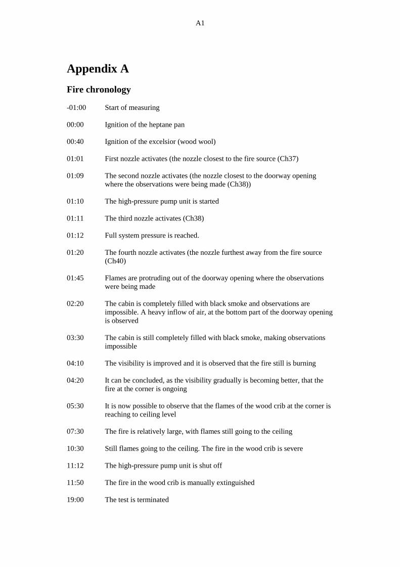
Figure A-7 The fire size prior to the full fire involvement of the polyether foam cushions.
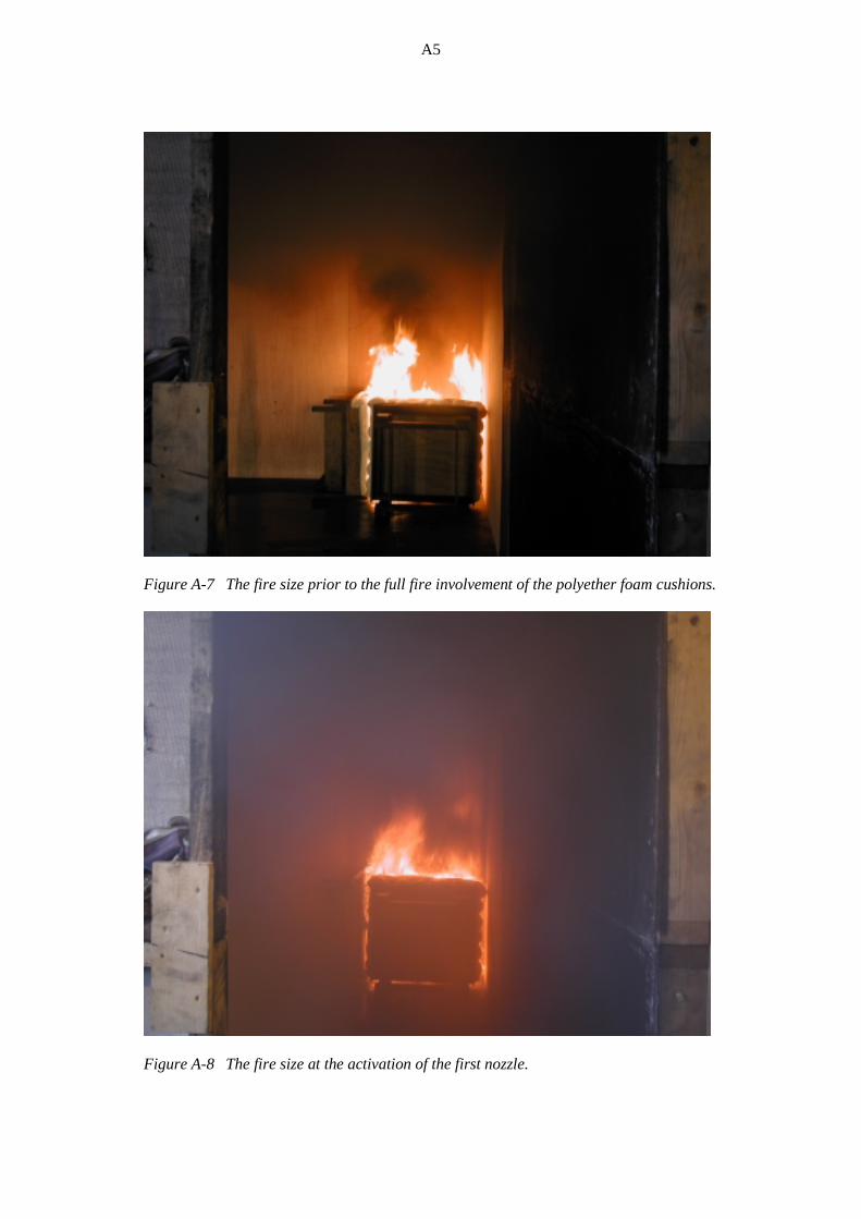
Figure A-8 The fire size at the activation of the first nozzle.

A6
Figure A-9 The luxury cabin after the test.
Figure A-10 The luxury cabin after the test, with the ‘simulated furniture’ removed.

SP Swedish National Testing and Research InstituteSP Fire TechnologySP REPORT 2003:01
SP Swedish National Testing and Research InstituteBox 857, SE-501 15 BORÅS, SwedenTelephone: + 46 33 16 50 00, Telefax: + 46 33 13 55 02E-mail: [email protected], Internet: www.sp.se
SP REPORT 2003:01ISBN 91-7848-927-XISSN 0284-5172
Magnus Arvidson
The IMO Resolution A.800 (19) luxury cabin fi re test procedure
Test experience and suggested revisions