the hydraulics of two flowing layers with different densitiesarmi.ucsd.edu/armi(1986).pdf · the...
TRANSCRIPT
J . Fluid Mech. (1986), vol. 163, pp . 27-58
Printed in Gent Britain 27
The hydraulics of two flowing layers with different densities
By LAURENCE ARM1 Scripps Institution of Oceanography, La Jolla, California 92093
(Received 24 August 1984 and in revised form 11 April 1985)
This is a theoretical and experimental study of the basic hydraulics of two flowing layers. Unlike single-layer flows, two-layer flows respond quite differently to bottom depth as opposed to width variations. Bottom-depth changes affect the lower layer directly and the upper layer only indirectly. Changes in width can affect both layers. In fact for flows through a contraction control two distinct flow configurations are possible; which one actually occurs depends on the requirements of matching a downstream flow. Two-layer flows can pass through internally critical conditions at other than the narrowest section. When the two layers are flowing in the same direction, the result is a strong coupling between the two layers in the neighbourhood of the control. For contractions a particularly simple flow then exists upstream in which there is no longer any significant interfacial dynamics; downstream in the divergent section the flow remains internally supercritical, causing one of the layers to be rapidly accelerated with a resulting instability at the interface. A brief discussion of internal hydraulic jumps based upon the energy equations as opposed to the more traditional momentum equations is included. Previous uniqueness problems are thereby avoided.
1. Introduction A new treatment of the internal hydraulics of two-layer flows is presented here that
allows simplification of the analysis of a wide range of practical and geophysical problems. The flows are parametrized in terms of the internal Froude numbers for each layer and possible flow solutions are shown as curves in the Proude-number plane. With this approach the conditions for critical flow, which define all of the essential characteristics of the internal hydraulics, take a particularly simple form. This then allows interpretation of solutions in such a way as to illustrate the location of controls, including virtual controls, of matching conditions and of multiple solutions. The use of a Froude-number parametrization also allows much simpler specification of the regularity equations from which the control conditions are readily identified.
Solutions were calculated for two-layer flows through contractions and over sills. The results lead to the unexpected conclusion that, for a contraction, specification of the flow rates alone does not always lead to a single unique solution. In the general case, with control at the narrowest section of a contraction, there are two distinct solutions, specification of which is actually observed, determined by downstream matcbing requirements. Laboratory experiments of two-layer flows through con- tractions confirm the existence of these two solutions as predicted by theory.
Finally, the theory is extended to provide a simple scheme for predicting the conjugate states of weak internal hydraulic jumps.
2 FLM 163
28 L. Armi
2. A brief history of internal hydraulics Although the internal hydraulics of a single layer, either beneath or above a
stagnant or passive layer, is discussed in standard references (cf. Prandtll952 ; Turner 1973, §3.2), the first study of a two-layer flow in which both layers interact and play a significant role in the establishment or control of the flow was by Stommel & Farmer (1953). An exchange flow with an internally critical condition at the mouth of an estuary was found to limit the amount of mixing that could occur in the estuary between fresh water and ocean water. Wood (1970) later studied the somewhat similar lock-exchange flow through a contraction which results from opening a lock gate between two fluids of different densities. The effect of friction on the motion of two layers was first considered by Schijf & Schonfeld (1953) starting with an assumed initial condition.
A special two-layer flow which behaves as a composite flow was recognized by Wood (1968) in treating the problem of withdrawal of a stratified fluid through a horizontal contraction, which also controls the level of the free surface. The requirement that the flow start from a stagnant reservoir and accelerate through a critical state with respect to the free-surface velocity was observed to force the flow to be internally critical at a virtual control upstream in the contraction. The resulting flow belongs to the special class of steady stratified flows of Yih (1969). This work was extended by Wood & Lei (1972) to the flow of a layered fluid over a broad-crested contracted weir and by Lai & Wood (1975) t o the withdrawal of two layers through separate valves, which are downstream of a contraction, for one specific reservoir condition. An analysis of boundary contractions as controls in two-layer flows was attempted by Mehrotra (19733) ; however, many of his conclusions, particularly regarding the equivalence of vertical and horizontal contractions and the position of the only control being at the narrowest section, are in disagreement with the findings presented here.
Long (1954, 1970, 1974) considered experimentally and analytically the blocking of a two-layer flow over a mountain ridge for initially uniform flow upstream and downstream. This problem was also considered numerically by Houghton & Isaacson (1970). More recently, Baines (1984) has presented a comprehensive treatment of these impulsively started flows. These problems are analysed in a fundamentally different way than the analysis to be presented here. Reservoir conditions, that is velocities with respect to the obstacle and interface depths, are imposed and solutions are computed with internal hydraulic jumps and/or rarefactions matching the flow in the neighbourhood of the obstacle with the reservoir state. Since these jumps may propagate, the volume flow rates in each layer are determined and are not free parameters. In the presentation here the volume rates are fixed and interface response and velocities are determined.
Internal hydraulic jumps for two moving layers were first treated by Benton (1954) who recognized that the principles of momentum conservation and decrease of energy are together insufficient to specify downstream conditions, given a complete descrip- tion of the upstream flow. The additional requirement that no momentum be trans- ferred between the layers was added by Yih & Guha (1955). The question of determining which of up to four possible conjugate states actually occurs, from among those predicted by the conservation-of-momentum equations alone, has been treated by Hayakawa (1970), Mehrotra & Kelly (1973), and Mehrotra (1973~). A simplified treatment of weak internal hydraulic jumps, using the much simpler conservation- of-energy equations to predict the conjugate state for an internal hydraulic jump,
Hydraulics of two f iwing layers with different densities 29
is presented here. It is clear from this approach that the conjugate state is unique. Recent experimental work by Wood & Simpson (1984), Chu & Baddour (1984) and Lawrence (1985) together with earlier work of Wilkinson & Wood (1971) for a single entraining layer has indicated that internal jumps, and in particular the mixing regions associated with them, can take on a variety of forms. Unlike free-surface flows, internal flows can transfer both mass and momentum from adjacent layers by entrainment and waves and can thereby adjust to a range of possible downstream states.
3. Steady-flow equations and controls In this section we derive solutions and regularity equations for one- and two-layer
hydraulics and discuss the result in terms of flows through channels of slowly varying breadth and depth. Although an infinite number of possible flows might exist for any given channel geometry, we will try to identify those that are in some sense asymmetric. This asymmetry is required if differing reservoir conditions upstream and downstream are to be linked by the flow. These asymmetrical flows are called ‘controlled ’ because certain distinct regularity conditions must be satisfied for them to exist. As an example, for the familar single layer flowing over a sill, an asymmetric flow only exists if the Froude number of the flow is unity at the sill crest. For two-layer flows similar although more complicated conditions will apply.
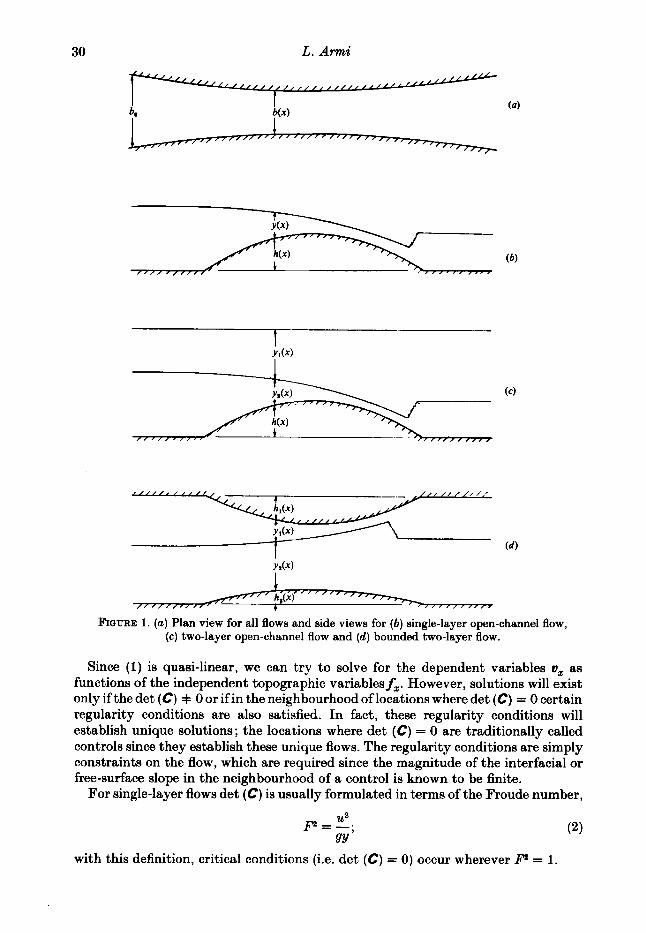
Figure 1 (a) shows a plan view for all flows and figures 1 (M) show side views of the three flow systems to be considered: (b) single-layer open-channel flow for comparison, and two-layer flows both with (c ) and without (d ) a free surface. Top and bottom variations are defined by hl ( z ) and ha@), or simply h(z) for free-surface flows. The width of the flow at any section is b(z). These are the independent topographic variables.
Subject to the assumptions of frictionless, uniform, one-dimensional hydrostatic flow, the steady momentum and continuity equations may be written in the general form :
This is a quasi-linear differential equation relating derivatives of the dependent variables u, to the derivatives of the independent topographic variables f,. The coefficients of (1) for two layers with a free surface are:
CU, = Of,. (1)
f=[3, ?.=A, P Pa
where u,, y,, p,, qt are respectively the layer velocity, thickness, density and volume flow rate. Subscript 1 will always refer to the upper layer and subscript 2 the lower layer. Specification of the coefficients and development of solutions for the cases of a single layer with a free surface and two-layer flow with a solid upper surface can be found in Appendix A. Appendix B contains a table of all symbols and definitions. Note that differentiation of the Bernoulli equations in the flow direction along with the continuity equations for each layer also gives (1).
2-2
30 L. A m i
Y h )
/ / ' &(if " ' " ' ' ,\ - 1 I I ,I II
FIGURE 1. (a) Plan view for all flows and side views for (b ) single-layer open-channel flow, (c) two-layer open-channel flow and (d) bounded two-layer flow.
Since (1) is quasi-linear, we can try to solve for the dependent variables u, as functions of the independent topographic variablesf,. However, solutions will exist only if the det (C) + 0 or if in the neighbourhood of locations where det (C) = 0 certain regularity conditions are also satisfied. In fact, these regularity conditions will establish unique solutions; the locations where det (C) = 0 are traditionally called controls since they establish these unique flows. The regularity conditions are simply constraints on the flow, which are required since the magnitude of the interfacial or free-surface slope in the neighbourhood of a control is known to be finite.
For single-layer flows det (C) is usually formulated in terms of the Froude number,
p=f; gY
with this definition, critical conditions (i.e. det (C) = 0) occur wherever P = 1.
Hydraulics of two $owing layers with different densities 31
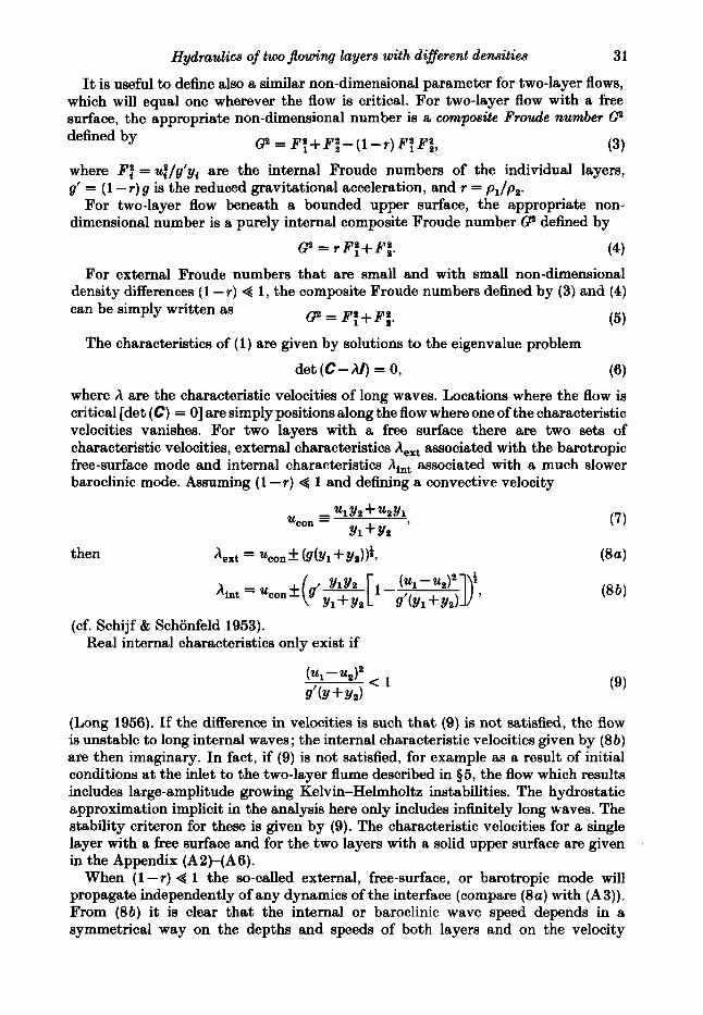
It is useful to define also a similar non-dimensional parameter for two-layer flows, which will equal one wherever the flow is critical. For two-layer flow with a free surface, the appropriate non-dimensional number is a composite F r d e number Ce defined by
where Ff = ui/g’yi are the internal Froude numbers of the individual layers, g’ = (1 - r ) g is the reduced gravitational acceleration, and r = p1/p2 .
For two-layer flow beneath a bounded upper surface, the appropriate non- dimensional number is a purely internal composite Froude number @ defined by
8 = PB,+F;-(l-T)FB,Pf, (3)
8 = r F t + F i . (4)
For external Froude numbers that are small and with small non-dimensional density differences (1 - r ) 4 1, the composite Froude numbers defined by (3) and (4) can be simply written as
clp = F : + F i .
The characteristics of (1) are given by solutions to the eigenvalue problem
det (C-A/) = 0, (6) where h are the characteristic velocities of long waves. Locations where the flow is critical [det (C) = 01 are simply positions along the flow where one of the characteristic velocities vanishes. For two layers with a free surface there are two sets of characteristic velocities, external characteristics A,, associated with the barotropic free-surface mode and internal characteristics Aint associated with a much slower baroclinic mode. Assuming (1 - r ) @ 1 and defining a convective velocity
(cf. Schijf t Schonfeld 1953). Real internal characteristics only exist if
(Long 1956). If the difference in velocities is such that (9) is not satisfied, the flow is unstable to long internal waves; the internal characteristic velocities given by ( 8 b ) are then imaginary. In fact, if (9) is not satisfied, for example as a result of initial conditions at the inlet to the two-layer flume described in $5, the flow which results includes large-amplitude growing Kelvin-Helmholtz instabilities. The hydrostatic approximation implicit in the analysis here only includes infinitely long waves. The stability criteron for these is given by (9). The characteristic velocities for a single layer with a free surface and for the two layers with a solid upper surface are given in the Appendix (A2)-(A6).
When ( l - r ) 4 1 the so-called external, free-surface, or barotropic mode will propagate independently of any dynamics of the interface (compare ( 8 a ) with (A3)). From (8b) it is clear that the internal or baroclinic wave speed depends in a symmetrical way on the depths and speeds of both layers and on the velocity

32 L. Armi
difference between the two layers. Relative to the convective velocity ucOn the internal and external waves travel at very different speeds.
Since (1) is quasi-linear, it may be solved for the dependent variables u, as functions of the independent variablesf,. This development was motivated by the similar treatment of compressible-flow problems in gasdynamics (cf. Liepmann BE Roshko 1957, p. 52, equation 2.27 and the following discussion of the area-velocity equation). For two layers with a free surface the solution is
Solutions for a single-layer flow and bounded two-layer flows are given in the Appendix (A7), (A8). At critical points, det (C) = 0, and the denominators of (1Ou-d) vanish; solutions only remain well behaved at these critical points if the numerators also vanish. These regularity conditions will specify uniqueness of the flows and determine the control locations.
First, the control of a single layer will be discussed as an introduction to the control of interfacial flows. If the bottom is everywhere level, the solution (A 7a,b) is
It is apparent that where the flow is critical, li"L = 1, the solution remains regular only if db/dx = 0. If only depth variations are considered, the same reasoning applies; critical flow can only occur a t a crest or location where dh/dx = 0. These two cases are discussed in detail in standard hydraulics texts.
However, the case for which both width and depth variations are encountered and the narrowest and highest points don't necessarily coincide gives an interesting new result. The following more complicated regularity condition must then be satisfied :
1 db 1 dh b dx ydx
-- - +--= 0.
If db/dx= 0 and dh/dx = 0 coincide, critical flow can be established at this coincidence location. If, however, the highest and narrowest sections do not coincide, critical flow will occur somewhere in between, as seen by the regularity condition (12) ; the location of the control is not uniquely specified by the geometry alone (h(x), b(x)), but also depends upon the flow rate that, together with the geometry, defines the layer depth y at the control. Thus the flow rate q determines the location of the control within the specified geometry.
The same effect, in which both geometry and flow rate together determine the control location, is also a characteristic of two-layer flows. Regularity conditions

Hydraulics of two $owing layers with different densities 33
similar to (12) can now be derived for a two-layer flow with a free upper surface by setting the composite Froude number G2 in (10) equal to unity :
1 d h - [ 1 - (1 +:) F ; ] f $+ [ - F;1 - - = 0,
-[ 1 -( 1 +:) F ; ] f ;+ [I - F:] - 1 d h - = 0,
Y1 dx
Y2 dx
c2 = F;+J’;-( l -r)F?F; = 1, ( 1 3 4 only two of the above three equations being independent.
Various authors have derived similar regularity conditions in their treatments of specific two-layer flow problems. Wood (1968) considered the two-layer flow with a free surface through a single contraction and Wood & Lai (1972) considered a two-layer flow over a broad-crested weir. Wood (1968) found it necessary for an additional control to exist for a flow starting from a reservoir and flowing through a contraction. The narrowest section controlled the level and dynamics of the free surface. The interfacial dynamics were controlled not by a geometrically prescribed position (e.g. the narrowest section) but instead by the location where the Composite Froude number was equal to unity. At this so-called ‘virtual control’ the regularity conditions established a unique solution. A virtual control is not limited to the problems considered by Wood and his collaborators, for which both the interfacial and free-surface dynamics are controlled by a single geometric control. It is encountered in all problems involving interfacial dynamics when the flow rates are sufficiently high that only internally supercritical conditions can occur at the normal control (dhldx or dB/dx = 0) and a transition occurs from sub- to supercritical conditions. Then the more complicated conditions of (13a-c) apply.
If the internal Froude number of one of the layers is small (P,Z Q l), inspection of (10) reveals that the resulting flow of the layer with finite Froude number is governed by a pair of equations identical with those for a single layer, with the appropriate internal Froude number replacing the free-surface Froude number. If the bottom layer is the moving layer, which has a finite internal Froude number, it will respond to width and bottom-level variations just as an independent single layer would; it would be unaffected by variations in the level of the bounding upper surface. Similarly, if the upper layer is the moving layer, which has a finite internal Froude number, it will respond only to width variations for flows bounded above by a free surface. If both internal Froude numbers have finite values, the flows are coupled.
If both internal Froude numbers are high, F; and Fi B 1, the stability requirement (9) implies that
This result can be used to rewrite the solutions for a two-layer flow with a free surface, as follows:
u; x u; (14)
1 aYr 1 3(Yl+Y2) Ys ax Y l + Y 2 ax . ---

34 L. Armi
The Froude number F is now just the external Froude number. At high internal Froude numbers, the two-layer flow behaves exactly as a single layer (compare (15u-c) with (A7a,b)). The internal dynamics are thus unimportant with regard to establishment of the free-surface level.
If the non-dimensional-density difference is small, the external Froude number will be 0(1 - r ) for G2 = O(1). The free surface with then remain level to 0(1 - r ) . The interfacial dynamics are dependent on the free-surface dynamics only to the extent of establishing the level of the free surface. Two-layer flows with a free surface and small non-dimensional-density difference behave exactly as bounded two-layer flows with the upper boundary level.
Since the internal dynamics of a two-layer flow can be treated independently of the dynamics of the free surface, the discussion of the control of an internal flow is the same for flows with a free upper surface as for flows with a horizontal upper boundary.
4. The Froude-number plane for two-layer flows We now discuss a new parametrization of the solutions applicable to two-layer
flow. This approach differs from that previously used (see, for example, Long 1970) in which solutions are expressed in terms of layer depths or speeds, in that we now use positions in the Froude-number plane (figure 2) to define solutions in terms of the essential nonlinearity of the flow. Moreover the critical condition,
c2 = F : + F i = 1 (( l-T) 4 l ) , (16)
collapses to a straight line, separating internally supercritical from internally subcritical flow.
With this parametrization i t is appropriate to specify the flow rate qi = uabyi for each layer. The flow rates qI, rather than the upstream interface position and layer speeds (see, for example, Baines 1984), are specified in the experiments discussed later, and this is often true of many practical applications such as river discharge into a stratified reservoir. However, i t is a straightforward matter to transform the results into layer thicknesses and speeds, using the definition of qi and q :
The solutions apply to two-layer flows beneath a free upper surface with the non-dimensional-density difference between the two layers assumed small ; they also apply to bounded flows without this assumption of small non-dimensional-density difference if, in all instances, the actual velocity of the upper layer u1 is replaced by &ul. For example, the Froude number of the upper layer would read rFt , for F:, and the volume flow would read &ql for q1 if a two-layer flow beneath a rigid upper surface is to be treated.
Using the continuity equation for each layer, and fixing the volume flow ratio qr, the loci of all possible Froude-number pairs for any volume flow rate, width and total depth of flow can be computed as follows. Define non-dimensional-volume flow
2.0
1 .5
F: 1.0
0.5
0
Hydraulics of two jlowing layers with different densities 35
4 r = 1
0.5 1 .o F:
1.5 2.0
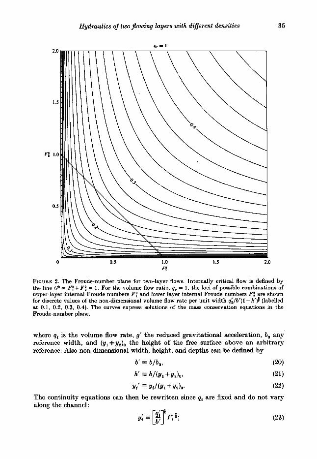
FIQURE 2. The Froude-number plane for two-layer flows. Internally critical flow is defined by the line G2 = B’? + F i = 1. For the volume flow ratio, qr = 1, the loci of possible combinations of upper-layer internal Froude numbers F: and lower layer internal Froude numbers F: are shown for discrete values of the non-dimensional volume flow rate per unit width ql/b’( 1 -h’)i (labelled at 0.1, 0.2, 0.3, 0.4). The curves express solutions of the mass conservation equations in the Froude-number plane.
where qz is the volume flow rate, g’ the reduced gravitational acceleration, bo any reference width, and the height of the free surface above an arbitrary reference. Also non-dimensional width, height, and depths can be defined by
b’ = b/bo , (20)
h’ = h/(Yl +YZ)O, (21)
Yt’ = Yt/(Yl +YZ)O. (22) The continuity equations can then be rewritten since qi are fixed and do not vary along the channel:

36 L. Armi
and the equation for a level free surface,
becomes
where qr = q1/q2 is the ratio of flow rates in each layer. Equation (25) defines the possible Froude-number pairs for any given qr and
[q;/b’(l -h’)i]. This is the only family of curves presented in figure 2 (for qr = 1). AS the interface between the two layers moves up and down, the possible Froude-number pairs are defined by each locus if all the other parameters are fixed. For flows through a contraction, total-depth variations can be ignored if the external Froude number is small. For this flow the non-dimensional height h’ may be taken to be zero above some reference. The parameterization for contractions is then simply the non- dimensional flow rate per unit width (qi /b’) . For flows over a sill the width remains constant and b’, the non-dimensional width, will be chosen to be unity. These sill flows are expressed in terms of the parameter [qi/(l -h’)f] .
The solution plane of figure 2 provides a background grid for all the solutions for qr = 1. With q1 and q2 fixed, qr and the parameter qi / [b’ ( 1 - h’)f] are known at any position along the flow. In the Froude-number plane solutions of the continuity equation, shown in figure 2 for qr = 1, will specify a locus of possible Froude-number pairs. As either the width or bottom changes, q;/[b’( 1 - h’)t] changes and the solutions to be presented will connect loci of possible Froude-number pairs. Contractions and sills are considered separately. The combined solutions of the energy and continuity equations will never explicitly involve the direction of the flow of either layer. The solutions, when they exist, are therefore valid for exchange flows as well as for flows in the same direction.
5. Two-layer flows through a contraction For flows through a contraction, both the bottom and top bounding surfaces remain
horizontal and the flow encounters only width variations. The Bernoulli or energy equations for the two layers are:
H1= tPl@+P19(Yl+Y2)+P;
H2 = tP2 % + P19Y1+ P2 9Y2 + P ; (27 1 where p , the pressure at the upper surface, is usually taken by definition to be zero for flows with a free upper surface.
Subtraction of one of these equations from the other removes the dominant effect of hydrostatic pressures not associated with the internal dynamics. In the absence of hydraulic jumps the resulting energy difference is a conservative quantity, just as the Bernoulli constant or total head is conservative for single-layer flows. In non-dimensional form this energy difference is :
For (1 - r ) Q 1, (18) and (29) can be combined :

Hydraulics of two #owing layers with different densities 37
2.0
1 .s
F: 1.0
0.5
0 0.5 1 .o I .5 2.0
F:
FIGURE 3. Solutions to the Bernoulli equations (the dark lines) in the Froude-number plane for (a) qr = 1 and (b) 0.5. Each solution curve is labelled with its non-dimensional reservoir height for the lower layer Yi. These solutions are superimposed on the maas-conservation loci (the light lines) also shown in figure 2 for qr = 1. Non-dimensional volume flow rates q;/b’ are labelled at 0.2, 0.3 and 0.4 on these loci.
For small internal Froude numbers (30) becomes
H2 - HI =-- y 2 - Y;, d P 2 (Y1+ Y z ) Y1+ Y2
where Y2 is the depth of the bottom layer at a reservoir. Figure 3 (a, b) shows solution curves for flows through a contraction for the volume
flow ratios qr = 1 and 0.5. The solutions of the energy equation are shown as heavy lines in the figure, overlying the loci of constant non-dimensional flow rates (shown in figure 2 for qr = 1). Additional solutions may be found in Armi (1975). The solutions for flows through a contraction are symmetric with respect to each of the two layers. Therefore, solutions for which the volume-flow ratio has a reciprocal value (qr = 2) to that shown in figure 3 (b) (qr = 0.5) can be found by merely interchanging the roles of the two layers. Each solution curve is labelled with the value of the non-dimensional reservoir interface height Y;.

38 L. Armi
qr = 0.5
0 0.5 I .o F:
1.5 2.0
FIQURE 3 ( b ) . For caption see preceding page.
If both internal Froude numbers are specified at the same location, such as a control, this specification uniquely determines the flow at all points along the solution curve. In this way the control fully determines the flow.
It is apparent from figures 2 and 3 ( a ) that, for volume flow rates qilb’ < 0.25, each flow-rate locus intersects the critical condition G2 = 1 twice. Therefore there are two possible controlled solutions through a contraction for each choice of flow rate. Of course there are an infinite number of non-unique subcritical solutions satisfying the flow rate, but these are not controlled by the contraction. This result can be generalized to arbitrary volume-flow ratios to give the maximum volume flow rate per unit width for which a critical flow can occur:
I
= q; l [ l+q; : ] -* .
If q;/b’ exceeds the value given by (31), there are no longer any intersections between the critical-flow line and the line of possible internal-Froude-number pairs for this value of qi /b’ . All possible internal-Froude-number pairs are internally
Hydraulics of two $owing layers with different densities 39
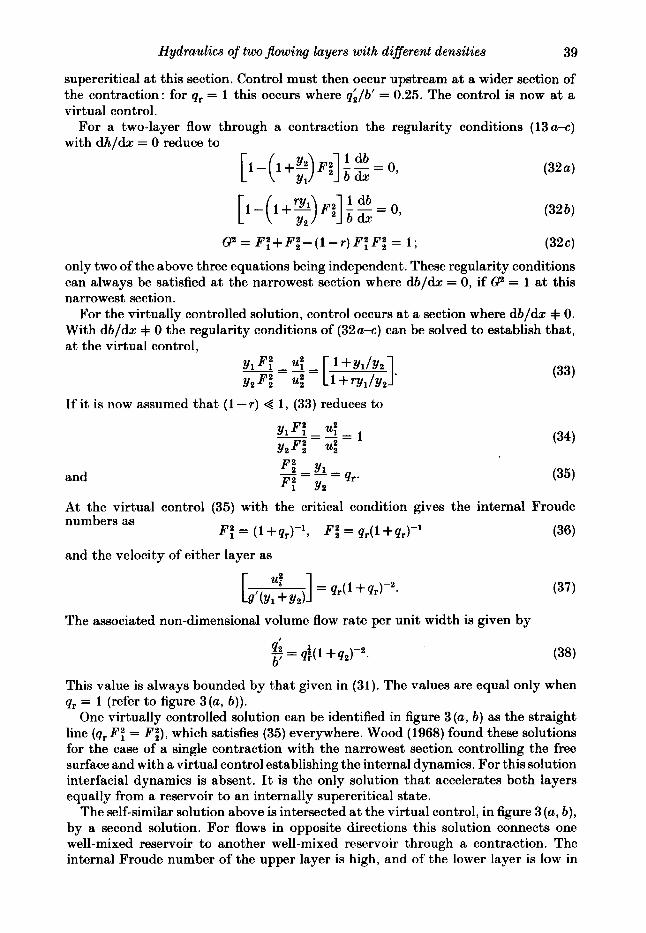
supercritical at this section. Control must then occur upstream at a wider section of the contraction: for qr = 1 this occurs where qi/b' = 0.25. The control is now at a virtual control.
For a two-layer flow through a contraction the regularity conditions (13 u-c) with dhldx = 0 reduce to
1 db
[ 1 - ( 1 + ~ ) F : ] ~ ~ = 1 db 0,
G2= F : + F i - ( l - r ) F t F i = 1 ; (324
only two of the above three equations being independent. These regularity conditions can always be satisfied at the narrowest section where dbldx = 0, if P = 1 at this narrowest section.
For the virtually controlled solution, control occurs at a section where db/dx =I= 0. With db/dx 9 0 the regularity conditions of (32a-c) can be solved to establish that, at the virtual control,
If i t is now assumed that ( 1 - r ) 4 1 , (33) reduces to
and (35)
At the virtual control (35) with the critical condition gives the internal Froude numbers as
and the velocity of either layer as
(36) F f = (1+qr)-', F i = q,(l+q,)-'
The associated non-dimensional volume flow rate per unit width is given by I + = d(l +q2)-2.
b
This value is always bounded by that given in (31) . The values are equal only when qr = 1 (refer to figure 3(a, b)).
One virtually controlled solution can be identified in figure 3 (a, b) as the straight line (q,P: = Pi), which satisfies (35) everywhere. Wood (1968) found these solutions for the case of a single contraction with the narrowest section controlling the free surface and with a virtual control establishing the internal dynamics. For this solution interfacial dynamics is absent. It is the only solution that accelerates both layers equally from a reservoir to an internally supercritical state.
The self-similar solution above is intersected at the virtual control, in figure 3 (a, b), by a second solution. For flows in opposite directions this solution connects one well-mixed reservoir to another well-mixed reservoir through a contraction. The internal Froude number of the upper layer is high, and of the lower layer is low in

40 L. Armi
the one reservoir, and the reverse situation occurs in the other reservoir. This is the solution found by Wood (1970) in investigating the lock-exchange flow for two flows in opposite directions.
6. Experiments The solutions generated and discussed in the previous section have been exhibited
in the laboratory. However, we have limited the treatment to flows for which the interface remains stable, particularly in the neighbourhood of the control or virtual control. Our primary interest is in controlled flows and certain phenomena are ignored, for example supercritical unstable jets.
For two-layer flows through a contraction it was found that two distinct flow configurations are possible. Flows with internally critical conditions at the narrowest section will be discussed first and then the flows with a virtual control, or critical flow at a section upstream of the narrowest section, are discussed.
The laboratory flume was 5.1 cm (2 in.) wide with transparent plastic walls, as shown in the photographs of figure 4 ( a d ) (Plate 1). The total flume length was 2 m. There was a sharp-crested overflow weir at the downstream end with which the free-surface level was controlled. Since the external Froude number was always very low, except at the weir itself, the free surface remained level. The inlet sections were separated by a splitter until beyond the end of a high-pressure-loss region. This was made by packing stainless-steel wool between sections of aluminium honeycomb. The purpose of these high pressure losses at the entrance was to make the flow uniform in each layer. Density differences between the two layers were produced by adding salt to the lower layer in a large mixing tank. The lower layer was dyed blue for visualization in the photographs and to facilitate measurement of the interface position ( f 1 mm). Densities were measured using a hydrometer, the accuracy of the density difference between the layers was 4 %. For each of the experiments, the volume flow rates of the layers were fixed.:These flow rates were measured with calibrated flow meters to + 2 % throughout the range of flow rates studied (30-150 cm3/s). Although the experiments were conducted for a number of flow rates, they were grouped in families characterized by the flow ratio qr being fixed.
A contraction was formed in the experimental flume by clamping thin plastic sheets against the inner walls. The start of the convergent section was always located a t 18 cm (7 in.), the narrowest section of width 2.27 cm a t 46 cm (18 in.), and the end to the divergence section at 74 cm (29 in.). Measurements were made a t these loca- tions, labelled l , 2, and 3 respectively, and can all be identified in the photographs by the presence of the thin transparent measuring rules (figure 4a-d). When an inverted bump or weir was inserted from above i t was 173 cm (68 in.) downstream of the entrance, as illustrated in figure 4 (b).
The combined errors in measurement of the internal Froude numbers Ff were between f 12 yo and & 40 yo, depending on the depth of the flow. A typical depth of 40 mm resulted in an error of approximately f 15 yo. Data are also presented using the non-dimensional depth y;, the accuracy of which is kO.01; the non-dimensional volume flow rate q; is accurate to f 5 yo.
The effects of a non-uniform flow are small and can be evaluated by considering the errors caused by assuming the energy-distribution coefficient a = 1 (Chow 1959, p. 28). The definition of the Froude numbers should include this energy-distribution coefficient, e.g.
0
Hydraulics of two jlowing layers with different densities
0.5 1 .o F:
I .5
41
.O
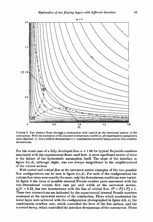
FIQURE 5. Two distinct flows through a contraction with control at the narrowest section of the contraction. With the exception of the imposed downstream condition, all experimental parameters were identical. 0, free overflow downstream ;w, combination inverted bump and the free overflow downstream.
For the worst case of a fully developed flow a = 1.06 for typical Reynolds numbers associated with the experimental flume used here. A more significant source of error is the failure of the hydrostatic assumption itself. The slope of the interface in figure 4 (c ,d) , although slight, was not always insignificant in the neighbourhood of the control section.
With control and critical j b w at the narrowest section examples of the two possible flow configurations can be seen in figure 4(c ,d) . For each of the configurations the volume flow rates were exactly the same, only the downstream conditions were varied. In figure 5 the locus of possible internal-Froude-number pairs associated with the non-dimensional volume flow rate per unit width at the narrowest section, p;/b’ = 0.23, has two intersections with the line of critical flow, c2 = F:+FX = 1. These two intersections are indicated by the experimental internal Froude numbers measured at the narrowest section of the contraction. Flows which accelerated the lower layer were achieved with the configuration photographed in figure 4 (b, c ) , the combination overflow weir, which controlled the level of the free surface, and the inverted bump, which controlled the interface downstream of the contraction. Flows
42 L . Armi
which accelerated the upper layer were achieved with the overflow weir alone downstream, figure 4 ( d ) . The experiments therefore confirm the existence of two solutions as predicted in our Froude-number-plane analysis.
With the inverted bump inserted downstream in the flume as shown in figure 4 ( b ) , the flow went through the contraction as illustrated in figure 4(c) (refer also to figure 5) . The lower layer was accelerated beginning at location 1 from subcritical conditions upstream through critical flow at the narrowest section, location 2, to supercritical conditions downstream. An internal hydraulic jump extends into the downstream end of the contraction, near location 3 ; here the supercritical flow leaving the contraction is conjugate to the subcritical flow upstream of the inverted bump.
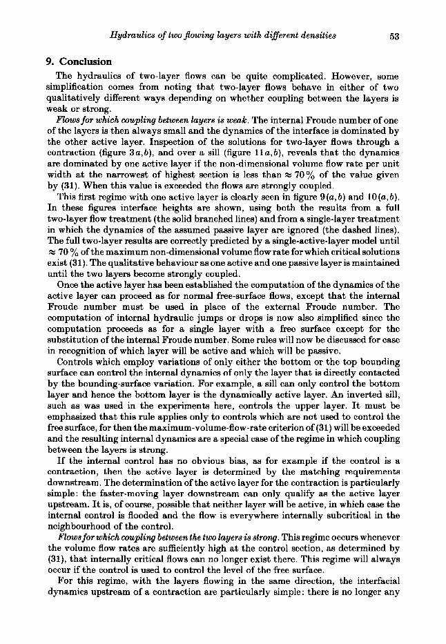
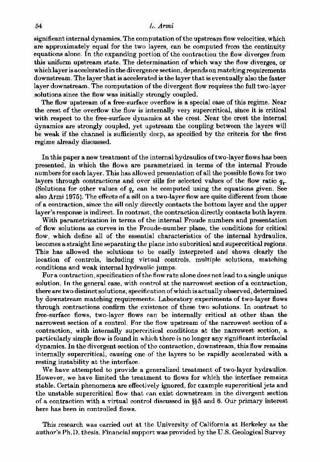
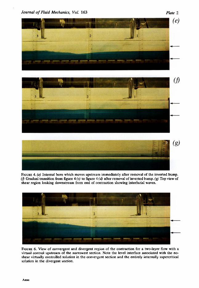
The transition from the flow with the inverted bump inserted to the flow configuration with only the free overflow downstream can be seen in figure 4 ( e , f ) (Plate 2). An internal bore, which moves upstream immediately after removal of the inverted bump, is seen in figure 4(e). After its passage there is some sloshing in the flume followed by a gradual filling in of the bottom-layer fluid. This continues until the interface rises to the level shown in figure 4(d ) and the new configuration, which accelerates the upper layer through the contraction, is established.
For the configuration figure 4 (d ) (refer also to figure 5 ) there is only a free overflow downstream. As the flow proceeds through the contraction, the upper layer is accelerated and conditions are subcritical at location 1, critical at the narrowest section, location 2, and supercritical downstream. Beginning at location 3, at the end of the divergent section of the contraction, there is a region characterized by large interfacial waves, shown in figure 4 (9) (Plate 2) where the flow decelerates.
Which, if either, of the two flows above is realized will depend on the conditions downstream of the contraction and the requirement that it be possible to match this downstream state.
If the reservoir height of the interface Yi due to the downstream control and frictional effects, is between the two values of Y; of the two distinct solutions with critical flow at the narrowest section (refer to figures 3a and 5 ) , then no possible jumps or shear regions can connect either of these solutions with the downstream state. The contraction will be flooded and can no longer act as a control. The reservoir interface height and hence the total solution through the contraction is determined by conditions downstream of the contraction.
If the reservoir height of the interface Y;, due to the downstream control and frictional effects, is less than the value of Yi associated with the solution for which the lower layer is the faster layer, then this is the solution which must occur in the convergent section of the contraction. Downstream of the narrowest section the value of Y;, established at the narrowest control section of the contraction, will be gradually reduced by interfacial shear until the flow is conjugate to the conditions upstream of the downstream control and an internal hydraulic jump matches the two controls. If the value of Y; computed at the narrowest section of the contraction is only slightly less than Y; established by the contraction, the internal hydraulic jump will occur close to the narrowest section of the contraction. The computed value of Yi at the narrowest section of the contraction, but due to the downstream control, may be so much less than Y; established in the contraction that the shear region never reduces the value of YL established by the contraction to a state conjugate to that computed at the downstream control. The flow will then be internally supercritical everywhere downstream of the narrowest section of the contraction and the ' downstream control ' is no longer an interfacial control.
If the reservoir height of the interface Yi, due to the downstream control and

0
Hydraulics of two $owing layers with different densities 43
0.5 1 .o F:
1.5 2 .o
FIQURE 7. Two distinct two-layer flows through a contraction with a virtual control upstream of the narrowest section. With the exception of the imposed downstream condition, all experimental parameters were identical. 0, free overflow downstream ;u, combination inverted bump and the free overflow downstream.
frictional effects, is greater than the value of Y; associated with the solution for which the upper layer is the faster layer, then this is the solution which must occur in the convergent section of the contraction. Downstream the matching occurs exactly as described above when the lower layer was the faster-moving layer, except that the effect of interfacial shear and internal hydraulic jumps will be t o increase the value of Y; associated with the solution a t the narrowest section.
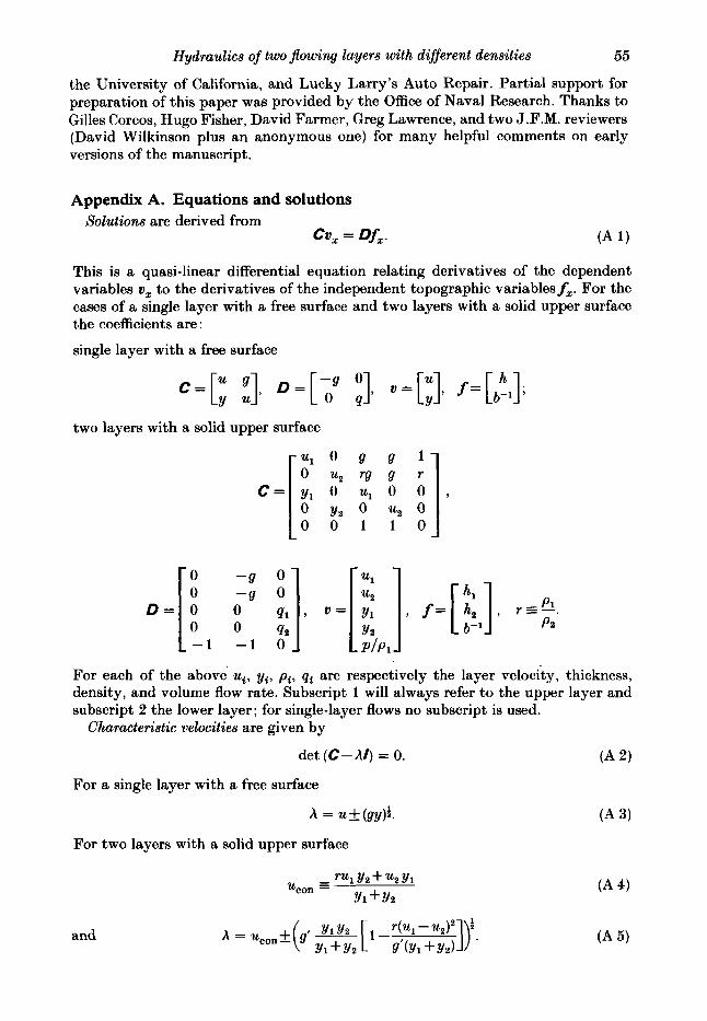
An example of a flow with a virtual control and criticalflow upstream of the narrowest section is shown in figure 6 (Plate 2). By increasing the volume flow rate per unit width qi/b’ the two distinct solutions with critical flow at the narrowest section merge to the no-shear virtually controlled solution, characterized by a level interface upstream of the narrowest section. No internally critical solutions existed a t the narrowest section, volume flow rates per unit width at the narrowest section, qi/b‘ = 0.36, are greater than given by (31). For a volume-flow ratio of unity, qr = 1, the volume flow per unit width needs to be such that qL/b’ > 0.25, as is seen in figure 7 , for a virtually controlled flow.
L. Armi
0
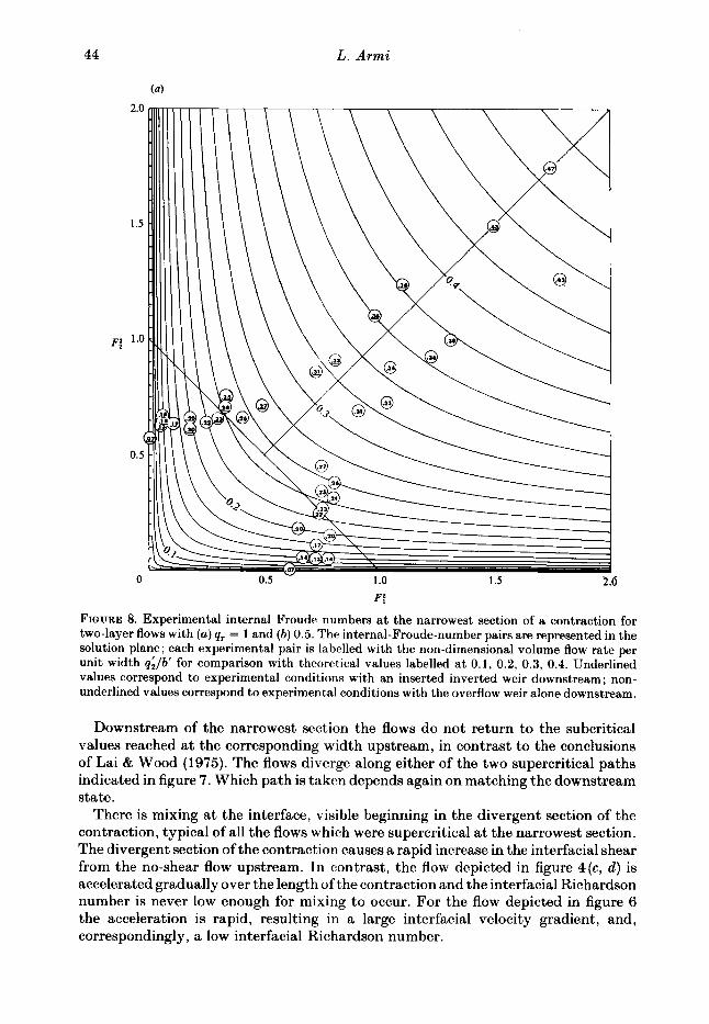
FIGURE 8. Experimental internal Froude numbers at the narrowest section of a contraction for two-layer flows with (a) qr = 1 and (b) 0.5. The internal-Froude-number pairs are represented in the solution plane; each experimental pair is labelled with the non-dimensional volume flow rate per unit width q;/b’ for comparison with theoretical values labelled at 0.1, 0.2, 0.3, 0.4. Underlined values correspond to experimental conditions with an inserted inverted weir downstream ; non- underlined values correspond t o experimental conditions with the overflow weir alone downstream.
Downstream of the narrowest section the flows do not return to the subcritical values reached a t the corresponding width upstream, in contrast to the conclusions of Lai & Wood (1975). The flows diverge along either of the two supercritical paths indicated in figure 7. Which path is taken depends again on matching the downstream state.
There is mixing a t the interface, visible beginning in the divergent section of the contraction, typical of all the flows which were supercritical at the narrowest section. The divergent section of the contraction causes a rapid increase in the interfacial shear from the no-shear flow upstream. In contrast, the flow depicted in figure 4(c, d ) is accelerated gradually over the length of the contraction and the interfacial Richardson number is never low enough for mixing to occur. For the flow depicted in figure 6 the acceleration is rapid, resulting in a large interfacial velocity gradient, and, correspondingly, a low interfacial Richardson number.

Hydraulics of two flowing layers with different densities
(b)
45
0 0.5 1 .O 1.5
F:
FIGURE 8(b) . For caption see facing page.
2.0
Qwcntitative results for these experiments can be displayed in the Froude-number plane first presented in $4. All experimental Froude numbers obtained at the narrowest section of the contraction are shown in figure 8(a, b ) for flow rates with control at the narrowest section, and for higher flow rates with supercritical composite Froude numbers at the narrowest section and a virtual control upstream in the contraction section. Each experimental pair is labelled with the non-dimensional volume flow rate per unit width q;/b‘ for comparison with values indicated along the loci. Underlined values correspond to experimental flows with the inserted inverted weir downstream ; non-underlined values correspond to experimental flows with the overflow weir downstream. The deviation of the experimental internal Froude numbers from theoretical values is in part due to the accumulated errors in the internal Froude numbers of approximately 15 %. The systematic deviation from the predicted values is due to ignoring curvature effects in the neighbourhood of the narrowest section. These systematic deviations are most severe for low values of the volume flow rates.
Figure 9 (a, b) show non-dimensional interface heights above the bottom y ; at the narrowest section, as a function of the non-dimensional volume flow rate qilb’ for
46 L. Armi
0
(b)
0.1 0.2 0.3 dlb'
0.4 0.5
1 .O
j~; 0.5
. . 1 .O I I I
A---- 4- A - -- -9 - - - :=>-=- -. _----
j~; 0.5 -
0.3 0.4 I 0.5 0.1 0.2 0 0
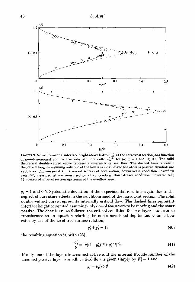
4lb' FIQURE 9. Non-dimensional interface height above bottom yi, at the narrowest section, as afunction of non-dimensional volume flow rate per unit width q;/b' for (a) qr = 1 and ( b ) 0.5. The solid theoretical double-valued curve represents internally critical flow. The dashed lines represent theoretical heights assuming only one of the layers is moving and the other is passive. Symbols are as follows: A, measured at narrowest section of contraction, downstream condition - overflow weir; V, measured at narrowest section of contraction, downstream condition - inverted sill; 0, measured in level section upstream of the overflow weir.
qr = 1 and 0.5. Systematic deviation of the experimental results is again due to the neglect of curvature effects in the neighbourhood of the narrowest section. The solid double-valued curve represents internally critical flow. The dashed lines represent interface height computed assuming only one of the layers to be moving and the other passive. The details are as follows: the critical condition for two-layer flows can be transformed to an equation relating the non-dimensional depths and volume flow rates by use of the level-free-surface relation,
y;+y; = 1 ;
the resulting equation is, with (23), I
(41) 412 - '-3 -1
If only one of the layers is assumed active and the internal Froude number of the assumed passive layer is small, critical flow is given simply by F: = 1 and
= (qi/b')i . (42 I
b'- [n:(l-Y;)-3++y, 1 *.
Hydraulics of two jlowing layers with diflerent densities 47
(4 1 .o
r; 0.5
0. I 0.2 0.3 0.4 0.5 0
1 .o
r; 0.5
4lb' b)
~
0 0.1 0.2 0.3 0.4 0.5 dlb'
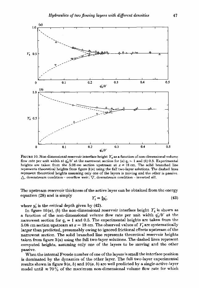
FIQURE 10. Non-dimensional reservoir interface height Y; as a function of non-dimensional volume flow rate per unit width a t q;/b' at the narrowest section for (a) qr = 1 and (b) 0.5. Experimental heights are taken from the 5.08 cm section upstream at x = 18 cm. The solid branched line represents theoretical heights from figure 3 (a ) using the full two-layer solutions. The dashed lines represent theoretical heights assuming only one of the layers is moving and the other is passive. A, downstream condition - overflow weir; V, downstream condition - inverted sill.
The upstream-reservoir thickness of the active layer can be obtained from the energy equation (28) and is simply
(43) Y; = gy;,
where yi is the critical depth given by (42). In figure lO(a), (b) the non-dimensional reservoir interface height Yi is shown as
a function of the non-dimensional volume flow rate per unit width qi/b' a t the narrowest section for qr = 1 and 0.5. The experimental heights are taken from the 5.08 cm section upstream at z = 18 cm. The observed values of Yj are systematically larger than predicted, presumably owing to ignored frictional effects upstream of the narrowest section. The solid branched line represents theoretical reservoir heights taken from figure 3 (a) using the full two-layer solutions. The dashed lines represent computed heights, assuming only one of the layers to be moving and the other passive.
When the internal Froude number of one of the layers is small the interface position is dominated by the dynamics of the other layer. The full two-layer experimental results shown in figure 9(a, b) and 10(a, b) are well predicted by a single-active-layer model until k: 70% of the maximum non-dimensional volume flow rate for which
48 L. Armi
2.0
1.5
F: 1.0
0.5
0 0.5 I .o F:
1.5 2.0
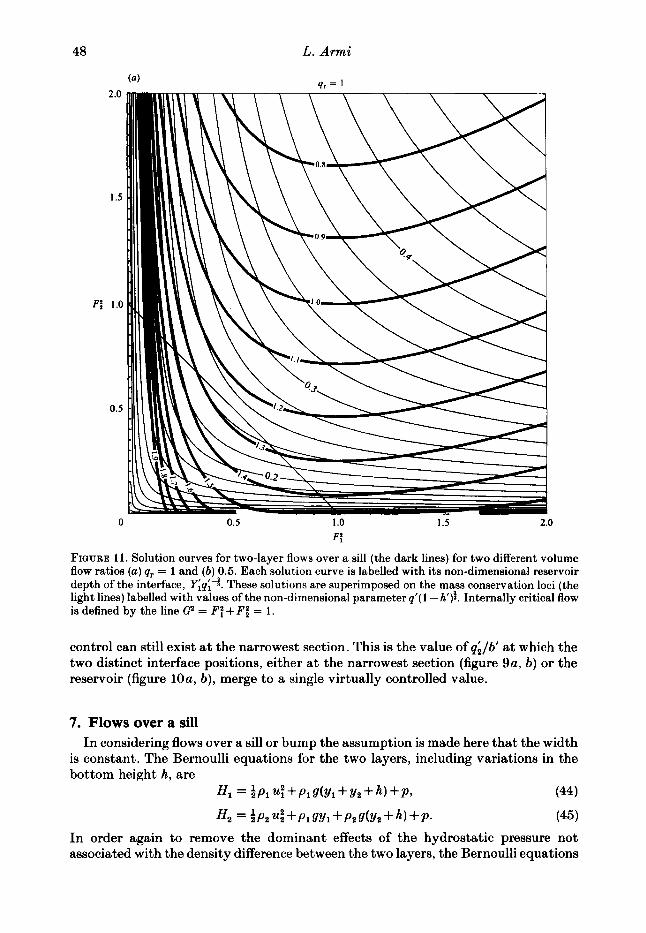
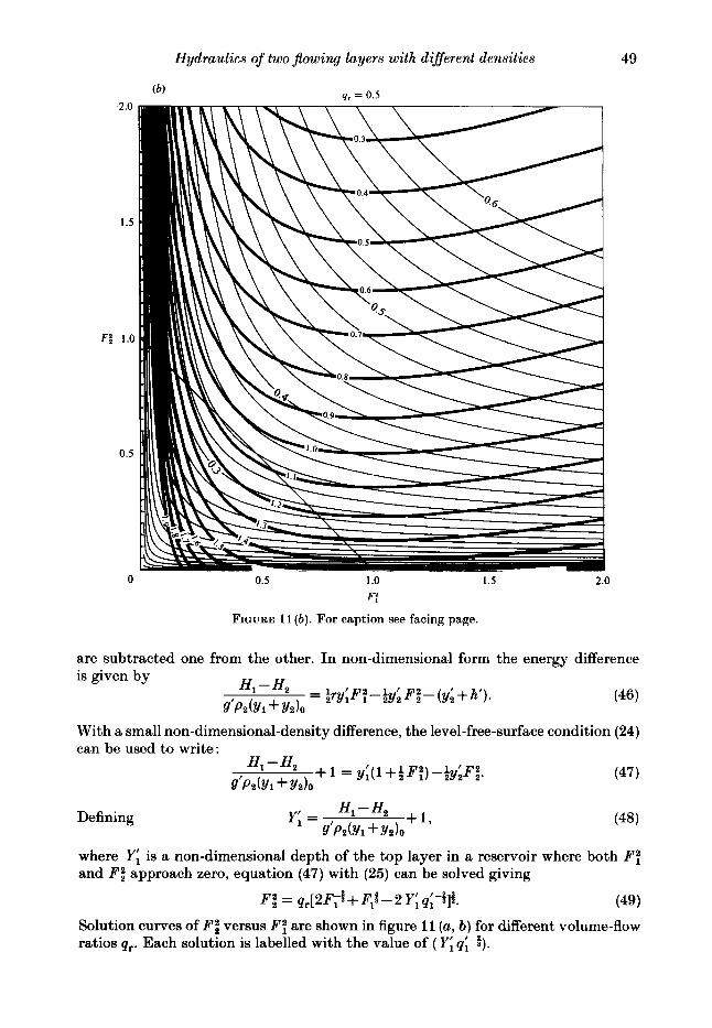
FIGURE 11. Solution curves for two-layer flows over a sill (the dark lines) for two different volume flow ratios (u) qr = 1 and (b) 0.5. Each solution curve is labelled with its non-dimensional reservoir depth of the interface, Yiqi-5. These solutions are superimposed on the mass conservation loci (the light lines) labelled with values of the non-dimensional parameter q‘( 1 -h’)i. Internally critical flow is defined by the line G2 = FT+ F: = 1.
control can still exist at the narrowest section. This is the value of qi/b’ at which the two distinct interface positions, either at the narrowest section (figure 9a, b) or the reservoir (figure 10a, b), merge to a single virtually controlled value.
7. Flows over a sill In considering flows over a sill or bump the assumption is made here that the width
is constant. The Bernoulli equations for the two layers, including variations in the bottom height h, are
4 = aPlU~+PlS(Y1+Yz+h)+P, (44)
H2 = aP2 4 +P1 SY1 +PZS(Y2 +4 +P. (45)
In order again to remove the dominant effects of the hydrostatic pressure not associated with the density difference between the two layers, the Bernoulli equations
2.0
1.5
F: 1.0
0.5
0
Hydraulics of two $owing layers with different densities 49
0.5 1 .o 1.5
F:
FIGUKE 11 (b). For caption see facing page.
2.0
are subtracted one from the other. In non-dimensional form the energy difference is given by
With a small non-dimensional-density difference, the level-free-surface condition (24) can be used to write:
Defining
where Yi is a non-dimensional depth of the top layer in a reservoir where both F: and F i approach zero, equation (47) with (25) can be solved giving
(49) Fi = q r [ 2 F ~ i + PI$ - 2 Y; qi-a]r.
Solution curves of F i versus F ; are shown in figure 11 (a, b) for different volume-flow ratios qr. Each solution is labelled with the value of ( Yi qi-5).
50 L. Armi
Inspection of the solutions of (10) and (A8) with db/dx = 0 reveals that they are symmetric. Flows beneath an inverted weir with a level bottom can therefore be treated by interchanging the roles of the two layers.
Changes in bottom and top bounding surfaces are felt directly only by the bottom and top layers, respectively. This is unlike a contraction, which contacts both layers. Contractions and bounding-surface variations are not equivalent (see (1Ou-d) and (A 8a-d) in contrast with the conclusions of Mehrotra (1973b).
As the flow moves over a sill, h’ increases and hence the parameter qi/(l -h’); is also increasing. At the crest the parameter is a maximum. The solution curves, shown in figure 11 (a ,b) , connect possible internal-Froude-number pairs for different bottom heights or values of the parameter q; / ( 1 - h’)f.
Flows which are initially subcritical can only have the bottom layer accelerated during flow over a sill. Critical flow can be seen from the solution curves to occur only a t the highest spot on the sill or largest value of the parameter a ; / ( 1 - h’);. For flows from a subcritical to supercritical state over a sill the internal Froude number of the bottom layer FZ increases continuously while the upper-layer internal Froude number F ; decreases continuously.
If the value of the parameter q; / ( 1 - h’); is sufficiently large, representing either high flow rates or high bumps, then the flow must be everywhere internally supercritical. The limiting value is given by
Inspection of the solution curves of figure 11 (a , b) shows that if the parameter &/( 1 - h’); is everywhere increasing, representing flow over an overflow weir, there are no solutions which connect a subcritical flow with a flow for which F ; is greater than one. Upstream of an overflow, which controls the free surface, and downstream of any other internal control, the flow must be internally a t least critical.
For two-layer flows a t constant width dbldx = 0 the regularity conditions
(514 reduce to
1 dh p - - = o 2 Y 1 d X
1 dh [l-P3 -- = 0,
Yz dx
only two of the above three equations being independent. The regularity conditions above imply the following unique results for two-layer flows over an overflow weir that controls the level of the free surface. The free surface will be controlled a t the crest where G2 = 1 ; a t the location of the control of the interface upstream of the crest, the regularity conditions with dh/dx =k 0 can be satisfied only if
F ; = 1 , F i = 0. (52)
This condition can only be reached in a deep reservoir. The deep-reservoir condition for flow over an overflow weir that controls the free surface is thus that the upper layer is internally critical and the lower layer has zero velocity. If the upstream reservoir is not deep, then critical conditions will be reached in the deepest section where dhldx = 0.
The above results indicate that, for a two-layer flow over an overflow that controls the free surface level, conditions upstream must be such that the flow is a t last
Hydraulics of two Jlowing layers with different densities 51
internally critical, G2 2 1. The condition G2 = 1 at the downstream end of the deepest-level section can be used as the downstream condition for the computation of a two-layer backwater curve using the equations of Schijf k SchGnfeld (1953) if the interfacial, bottom and surface stresses are known. (The surface stress can usually be ignored.)
Since the internal dynamics of a two-layer flow can be treated independently of the dynamics of the free surface, the discussion of the control of an internal flow is the same for flows with a free upper surface and with a level upper surface. If the bounding upper surface is not horizontal, as might occur in a stratified-flow wind tunnel or withdrawal from a two-layer flow at some depth below the free surface, then the regularity conditions will contain the effects of variation of the upper bounding surface. Setting CZ = 1 in (A 8) gives the regularity conditions for a two-layer bounded flow as follows:
CZ = r F t + F i = 1. (53 b)
If no width variations are present, and both the bounding sudaces are not level (the case where the upper surface was level was just discussed in the treatment of regularity conditions for a two-layer flow over an overflow weir), a virtual control can satisfy the regularity conditions at a location other than the shortest section where dh,/dx = dh2/dz = 0. The necessary conditions will then be
If both the width and depth variations are included the more complicated regularity conditions given by (53a) need to be satisfied when the flow is forced to be internally critical at some location other than the shortest, more-contracted section.
8. Weak internal hydraulic jumps For single-layer flows, the matching of the supercritical flow downstream of one
control with the upstream subcritical flow of the next control is accomplished with a hydraulic jump. For a two-layer flow this matching may also take place with an internal hydraulic jump if conditions are such that two conjugate states can exist. The classical internal hydraulic jump was modelled by Yih k Guha (1955), Hayakawa (1970), Mehrotra & Kelly (1973), and Mehrotra (1973a), after the free-surface hydraulic jump. The momentum flux of each layer is usually assumed to be conserved, that is no transfer of momentum from one layer to the other is assumed to occur. Recent experimental work by Wood & Simpson (1984), Chu & Baddour (1984) and Lawrence (1985) together with earlier work of Wilkinson k Wood (1971) has shown that internal jumps and the mixing regions associated with them take on a variety of forms owing to entrainment between the layers and radiation away from the jump region by internal waves. However, for weak internal hydraulic jumps these effects can often be ignored and a somewhat simplified treatment of these weak jumps may be made using solutions to the energy equations displayed in figures 3 (a) and (b) rather than by the previously cited more complicated treatments involving the momentum equations. The validity of this approach will be limited to weak jumps with no entrainment between the layers.

52 L. Armi
The energy change AH in a weak single-layer hydraulic jump can be shown, with the use of the hydraulic-jump conditions, to be well approximated by
AH - = & ( 1 - ~ ; ) 3 , SY c
(55)
where yo and Fi refer to upstream values of the depth and Froude number. Since the critical depth is two-thirds of the reservoir depth, the change in the reservoir depth
(56) is given approximately by AY
- x &(1 -F33. Y
For two-layer internal hydraulic jumps a similar relationship also applies for weak jumps, i.e.
= h(1 - ~ 3 3 , (57) yi
where CZ, is the upstream composite internal Froude number. The change in reservoir depth is negative, as it is for the single-layer hydraulic jump, and is always with respect to the reservoir depth of the faster-moving layer upstream of the internal hydraulic jump. A change in the upper-layer reservoir depth represents an internal hydraulic drop if the upper layer is the faster-moving layer upstream. If the upstream composite internal Froude number has the value Gi = 1.5, use of (56) shows that
It is therefore appropriate to use conservation of energy to predict the downstream state given the upstream state for weak jumps with Gi < 1.5. If CZ, > 1.5, (57) can be used in conjunction with the labelled reservoir depths to predict the downstream state. For high-upstream composite internal numbers the approach suggested here can only give qualitative results since we ignore effects of entrainment.
To find the conjugate state for a weak internal hydraulic jump or drop with the solutions in figures 3 (a, b) merely follow the line of constant total depth, for which the parameter q;/b’ is fixed, from the value at the upstream state G2 > 1 through the critical flow line until the solution curve is crossed again in the subcritical region. If > 1.5 the same procedure is used but the state downstream is not determined by completely conserving the upstream reservoir depth as above; the change in reservoir depth will be approximately given by (57).
The results of determining internal hydraulic jumps by the use of the energy and continuity equations described above clearly show that only one conjugate subcritical flow can exist for a given supercritical flow and that, if the volume flow rates per unit width are sufficiently high, no conjugate state exists. This agrees with the results of Mehrotra & Kelly (1973) and Mehrotra (1973~) . The actual limiting values of the volume flow rates per unit width for which internal hydraulic jumps no longer exist can now also be determined, and are just the maximum volume flow rates per unit width for which subcritical flows no longer exist.
Since variations of bottom height and width affect two-layer flows in very different ways, it is not surprising that there are many combinations of these two controls which cannot be matched by a jump that does not transfer momentum and/or mass from one layer to the other. If the matching requires the transfer of momentum from one layer to the other, the region in which the transfer occurs will be called a shear region as shown in figure 4 (9). The matching of two flows may require a combination of a shear region followed by a classical internal hydraulic jump.
Hydraulics of two $owing layers with different densities 53
9. Conclusion The hydraulics of two-layer flows can be quite complicated. However, some
simplification comes from noting that two-layer flows behave in either of two qualitatively different ways depending on whether coupling between the layers is weak or strong.
Flows for which coupling between layers is weak. The internal Froude number of one of the layers is then always small and the dynamics of the interface is dominated by the other active layer. Inspection of the solutions for two-layer flows through a contraction (figure 3a,b) , and over a sill (figure lla,b), reveals that the dynamics are dominated by one active layer if the non-dimensional volume flow rate per unit width at the narrowest of highest section is less than w 70% of the value given by (31). When this value is exceeded the flows are strongly coupled.
This first regime with one active layer is clearly seen in figure 9 (a, b) and 10 (a, b). In these figures interface heights are shown, using both the results from a full two-layer flow treatment (the solid branched lines) and from a single-layer treatment in which the dynamics of the assumed passive layer are ignored (the dashed lines). The full two-layer results are correctly predicted by a single-active-layer model until x 70 % of the maximum non-dimensional volume flow rate for which critical solutions exist (31). The qualitative behaviour as one active and one passive layer is maintained until the two layers become strongly coupled.
Once the active layer has been established the computation of the dynamics of the active layer can proceed as for normal free-surface flows, except that the internal Froude number must be used in place of the external Froude number. The computation of internal hydraulic jumps or drops is now also simplified since the computation proceeds as for a single layer with a free surface except for the substitution of the internal Froude number. Some rules will now be discussed for ease in recognition of which layer will be active and which will be passive.
Controls which employ variations of only either the bottom or the top bounding surface can control the internal dynamics of only the layer that is directly contacted by the bounding-surface variation. For example, a sill can only control the bottom layer and hence the bottom layer is the dynamically active layer. An inverted sill, such as was used in the experiments here, controls the upper layer. It must be emphasized that this rule applies only to controls which are not used to control the free surface, for then the maximum-volume-flow-rate criterion of (31) will be exceeded and the resulting internal dynamics are a special case of the regime in which coupling between the layers is strong.
If the internal control has no obvious bias, as for example if the control is a contraction, then the active layer is determined by the matching requirements downstream. The determination of the active layer for the contraction is particularly simple: the faster-moving layer downstream can only qualify as the active layer upstream. It is, of course, possible that neither layer will be active, in which case the internal control is flooded and the flow is everywhere internally subcritical in the neighbourhood of the control.
Flows for which coupling between the two layers is strong. This regime occurs whenever the volume flow rates are sufficiently high at the control section, as determined by (31), that internally critical flows can no longer exist there. This regime will always occur if the control is used to control the level of the free surface.
For this regime, with the layers flowing in the same direction, the interfacial dynamics upstream of a contraction are particularly simple: there is no longer any
54 L. Armi
significant internal dynamics. The computation of the upstream flow velocities, which are approximately equal for the two layers, can be computed from the continuity equations alone. In the expanding portion of the contraction the flow diverges from this uniform upstream state. The determination of which way the flow diverges, or which layer is accelerated in the divergence section, depends on matching requirements downstream. The layer that is accelerated is the layer that is eventually also the faster layer downstream. The computation of the divergent flow requires the full two-layer solutions since the flow was initially strongly coupled.
The flow upstream of a free-surface overflow is a special case of this regime. Near the crest of the overflow the flow is internally very supercritical, since it is critical with respect to the free-surface dynamics at the crest. Near the crest the internal dynamics are strongly coupled, yet upstream the coupling between the layers will be weak if the channel is sufficiently deep, as specified by the criteria for the first regime already discussed.
In this paper a new treatment of the internal hydraulics of two-layer flows has been presented, in which the flows are parametrized in terms of the internal Froude numbers for each layer. This has allowed presentation of all the possible flows for two layers through contractions and over sills for selected values of the flow ratio qr. (Solutions for other values of qr can be computed using the equations given. See also Armi 1975). The effects of a sill on a two-layer flow are quite different from those of a contraction, since the sill only directly contacts the bottom layer and the upper layer’s response is indirect. In contrast, the contraction directly contacts both layers.
With parametrization in terms of the internal Froude numbers and presentation of flow solutions as curves in the Froude-number plane, the conditions for critical flow, which define all of the essential characteristics of the internal hydraulics, becomes a straight line separating the plane into subcritical and supercritical regions. This has allowed the solutions to be easily interpreted and shows clearly the location of controls, including virtual controls, multiple solutions, matching conditions and weak internal hydraulic jumps.
For a contraction, specification of the flow rate alone does not lead to a single unique solution. In the general case, with control at the narrowest section of a contraction, there a,re two distinct solutions, specification of which is actually observed, determined by downstream matching requirements. Laboratory experiments of two-layer flows through contractions confirm the existence of these two solutions. In contrast to free-surface flows, two-layer flows can be internally critical at other than the narrowest section of a control. For the flow upstream of the narrowest section of a contraction, with internally supercritical conditions at the narrowest section, a particularly simple flow is found in which there is no longer any significant interfacial dynamics. In the divergent section of the contraction, downstream, this flow remains internally supercritical, causing one of the layers to be rapidly accelerated with a resting instability at the interface.
We have attempted to provide a generalized treatment of two-layer hydraulics. However, we have limited the treatment to flows for which the interface remains stable. Certain phenomena are effectively ignored, for example supercritical jets and the unstable supercritical flow that can exist downstream in the divergent section of a contraction with a virtual control discussed in §§5 and 6. Our primary interest here has been in controlled flows.
This research was carried out a t the University of California at Berkeley as the author’s Ph.D. thesis. Financial support was provided by the U.S. Geological Survey
Hydraulics of two flowing layers with diflerent densities 55
the University of California, and Lucky Larry's Auto Repair. Partial support for preparation of this paper Wa8 provided by the Office of Naval Research. Thanks to Gilles Corcos, Hugo Fisher, David Farmer, Greg Lawrence, and two J.F.M. reviewers (David Wilkinson plus an anonymous one) for many helpful comments on early versions of the manuscript.
Appendix A. Equations and solutions Solutions are derived from
CU, = Of,.
This is a quasi-linear differential equation relating derivatives of the dependent variables u, to the derivatives of the independent topographic variablesf,. For the cases of a single layer with a free surface and two layers with a solid upper surface the coefficients are :
single layer with a free surface
two layers with a solid upper surface [" 0 9 9 uz .", ; '1 c = y1 0 ,
0 Yz 0 uz 0 0 0 1 1 0
For each of the above ut, yr, pc, qr are respectively the layer velocity, thickness, density, and volume flow rate. Subscript 1 will always refer to the upper layer and subscript 2 the lower layer; for single-layer flows no subscript is used.
Characteristic velocities are given by
det (C-A/) = 0.
A = u f (gyp.
(A 2)
For a single layer with a free surface
(A 3)
For two layers with a solid upper surface
and

56 L. Armi
Real internal characteristics only exist if
T(U1 -U2l2 < 1. A?/, +Y2)
Using definitions of Froude number (2), internal Froude numbers, and composite Froude number (5 ) , the differential solutions to (A 1 ) for the steady flows are as follows :
single layer with a free surface
Appendix B. Symbols and definitions subscript i = 1 subscript i = 2 subscript ext subscript int b b‘ = b/bo b0
F = u2/gy e = Wg’Yi c2 = r q + q c2 = q + l q - ( l - r ) q E
upper layer lower layer external or free surface internal width non-dimensional width width at some reference external Froude number internal Froude number internal composite Froude number composite Froude number for two layer flows with free
gravitational acceleration reduced gravitational acceleration total energy or head height above reference non-dimensional height pressure at upper bounding surface volume flow rate non-dimensional volume flow rate
surface

Hydraulics of two $owing layers with different densities 57
q;/b’( 1 - h’); non-dimensional volume flow rate unit width
ratio of volume flow rates density ratio convection velocity average velocity of layer downstream distance reservoir layer thickness non-dimensional reservior layer thickness layer thickness non-dimensional layer thickness energy distribution coefficient characteristic velocity layer density
(for contraction solutions h’ = 0, for weir solutions b‘ = 1)
R E F E R E N C E S
ARMI, L. 1975 The internal hydraulics of two flowing layers of different densities. Ph.D. thesis,
BENTON, G. S. 1954 The occurrence of critical flow and hydraulic jumps in a multi-layered fluid
BAJNES, P. G. 1984 A unified description of two-layer flow over topography. J . Fluid Mech. 146,
CHOW, V. T. 1959 Open-Channel Hydraulics. McGraw-Hill. CHU, V. H. & BADDOUR, R. E. 1984 Turbulent gravity-stratified shear flows. J . Fluid Mech. 138,
HAYAKAWA, N. 1970 Internal hydraulic jump in co-current stratified flow. J. E7lgng Mech. Div.
HOUQHTON, D. D. & ISAACSON, E. 1970 Mountain winds. Stud. Numer. Anal. 2, 21-52. LAI, K. K. & WOOD, I. R. 1975 A two-layer flow through a contraction. J. Hyd. Res. IAHR 13,
LAWRENCE, G. A. 1985 Mixing in steady two-layer flow over topography. Ph.D. thesis, University
LIEPMANN, H. W. & ROSHKO, A. 1957 Elements of hdynamics . John Wiley and Sons. LONG, R. R. 1954 Some aspects of the flow of stratified fluids. 11. Experiments with a two-fluid
LONQ, R. R. 1956 Long waves in a two-fluid system. J . Met. 13, 7+74. LONQ, R. R. 1970 Blocking effects in flow over obstacles. Tellus 22,471480. LONQ, R. R. 1974 Some experimental observations of upstream disturbances in a two-fluid system.
Tellus 26, 3 13-3 17. MEHROTRA, S. C. 1973a Limitations on the existence of shock solutions in a two-fluid system. Tellus
25, 169-173. MEHROTRA, S. C. 1973b Boundary contractions as controls in two-layer flows. J . Hydr. Div. ASCE
99, HY11,2003-2012. MEHROTRA, S. C. & KELLY, R. E. 1973 On the question of non-uniqueness of internal hydraulic
jumps and drops in a two-fluid system. Tellus 25, 560-566. PRANDTL, L. 1952 Essentials of Fluid Dynamics. Blackie and Son. SCHIJF, J. B. & SCHONFELD, J. C. 1953 Theoretical considerations on the motion of salt and fresh
water. In Proc. of the Minn. Int. Hydraulics Conv., Joint meeting IAHR and Hyd. Div ASCE., Sept. 1953, pp. 321-333.
STOMMEL, H. & FARMER, H. G. 1953 Control of salinity in an estuary by a transition. J. Mar. Res. 12, 13-20.
TURNER, J. S. 1973 Bouyancy Eflects in Fluids. Cambridge University Press.
University bf California Berkeley.
system. J . Met. 11, 134-150.
127-1 67.
353-378.
ASCE 96 (EMS), 797-800.
1!3-34.
of California, Berkeley.
system. Tellus 6,97-115.

58 L. Armi
WILKINSON, D. L. & WOOD, I. R. 1971 A rapidly varied flow phenomenon in a two-layer flow.
WOOD, I. R. 1968 Selective withdrawal from a stably stratified fluid. J . Fluid Mech. 32, 209-223. WOOD, I. R. 1970 A lock exchange flow. J . Fluid Mech. 42, 671-687. WOOD, I. R & LAI, K. K. 1972 Flow of layered fluid over broad crested weir. J . Hyd. Div. ASCE
WOOD, I. R. & SIMPSON, J. E. 1984 Jumps in layered miscible fluids. J . Fluid Meeh. 140,329-342. Ym, C . S. 1969 A class of solutions for steady stratified flows. J . Fluid Meeh. 36, 75-85. YIH, C. S. & GUHA, C. R. 1955 Hydraulic jump in a fluid system of two layers. Tellus 7, 358-366.
J . Fluid Mech. 47, 241-256.
98, 87-104.

Journal of Fluid Mechanics, Vol. 163 Plate 1
(4
F~GURE 4. (a) Top view of experimental flume showing the placement of the false walls which formed the contraction section. (b) Overall view of flow through a contraction with downstream condition the combination inverted bump and the overflow weir. Flow is always from right to left. Horizontal scale is in inches (2.5 cm). For clarity, the inverted bump and free surface have been enhanced with solid black lines. (c) View of flow through a contraction with downstream condition the combination inverted bump and the overflow wier. An internal hydraulic jump is located at the downstream end of the contraction where the internally supercritical flow is conjugate to the subcritical flow upstream of the inverted bump. (d) View of flow through a contraction with a free overflow downstream.
(Facing p. 58)
Journal of Fluid Mechanics, Vol. 163 Plate 2
FIGURE 4. (e) Internal bore which moves upstream immediately after removal of the inverted bump. (j Gradual transition from figure 4 (c) t o figure 4 (d) after removal of inverted bump. (g) Top view of shear region looking downstream from end of contraction showing interfacial waves.
FIGURE 6. View of convergent and divergent region of the contraction for a two-layer flow with a virtual control upstream of the narrowest section. Note the level interface associated with the no- shear virtually controlled solution in the convergent section and the entirely internally supercritical solution in the divergent section.