the high energy density scientific instrument at the
TRANSCRIPT

research papers
J. Synchrotron Rad. (2021). 28, 1393–1416 https://doi.org/10.1107/S1600577521007335 1393
Received 6 March 2021
Accepted 15 July 2021
Edited by Y. Amemiya, University of Tokyo,
Japan
Keywords: high energy density; X-ray
free-electron lasers; warm dense matter;
high-pressure science; relativistic
laser–matter interaction.
The High Energy Density Scientific Instrument atthe European XFEL
Ulf Zastrau,a* Karen Appel,a Carsten Baehtz,b Oliver Baehr,b Lewis Batchelor,a
Andreas Berghauser,b Mohammadreza Banjafar,a,b Erik Brambrink,a
Valerio Cerantola,a Thomas E. Cowan,b Horst Damker,c Steffen Dietrich,b
Samuele Di Dio Cafiso,b Jorn Dreyer,b Hans-Olaf Engel,b Thomas Feldmann,a
Stefan Findeisen,b Manon Foese,c Daniel Fulla-Marsa,a Sebastian Gode,a
Mohammed Hassan,b Jens Hauser,b Thomas Herrmannsdorfer,b Hauke Hoppner,b
Johannes Kaa,e,a Peter Kaever,b Klaus Knofel,b Zuzana Konopkova,a
Alejandro Laso Garcıa,b Hanns-Peter Liermann,c Jona Mainberger,c
Mikako Makita,a Eike-Christian Martens,a Emma E. McBride,a,f Dominik Moller,b
Motoaki Nakatsutsumi,a Alexander Pelka,b Christian Plueckthun,a
Clemens Prescher,c Thomas R. Preston,a Michael Roper,c Andreas Schmidt,a
Wolfgang Seidel,b Jan-Patrick Schwinkendorf,a Markus O. Schoelmerich,a
Ulrich Schramm,b Andreas Schropp,c Cornelius Strohm,c Konstantin Sukharnikov,a
Peter Talkovski,c Ian Thorpe,a Monika Toncian,b Toma Toncian,b
Lennart Wollenweber,a Shingo Yamamotob and Thomas Tschentschera
aEuropean XFEL, Holzkoppel 4, 22869 Schenefeld, Germany, bHelmholtz-Zentrum Dresden-Rossendorf eV, 01328
Dresden, Germany, cDeutsches Elektronen-Synchrotron DESY, 22607 Hamburg, Germany, eTechnische Universitat
Dortmund, 44227 Dortmund, Germany, and fSLAC National Accelerator Laboratory, Menlo Park, CA 94025, USA.
*Correspondence e-mail: [email protected]
The European XFEL delivers up to 27000 intense (>1012 photons) pulses per
second, of ultrashort (�50 fs) and transversely coherent X-ray radiation, at a
maximum repetition rate of 4.5 MHz. Its unique X-ray beam parameters enable
groundbreaking experiments in matter at extreme conditions at the High
Energy Density (HED) scientific instrument. The performance of the HED
instrument during its first two years of operation, its scientific remit, as well as
ongoing installations towards full operation are presented. Scientific goals of
HED include the investigation of extreme states of matter created by intense
laser pulses, diamond anvil cells, or pulsed magnets, and ultrafast X-ray methods
that allow their diagnosis using self-amplified spontaneous emission between 5
and 25 keV, coupled with X-ray monochromators and optional seeded beam
operation. The HED instrument provides two target chambers, X-ray spectro-
meters for emission and scattering, X-ray detectors, and a timing tool to correct
for residual timing jitter between laser and X-ray pulses.
1. Scientific scope
The High Energy Density (HED) scientific instrument at
the European X-ray Free-Electron Laser Facility GmbH
(European XFEL) (Tschentscher et al., 2017; Decking et al.,
2020) is a unique platform for experiments combining hard
X-ray free-electron laser radiation with the capability to
generate matter at extreme conditions of pressure, tempera-
ture, or electromagnetic fields. The instrument started user
operation in May 2019 and will augment its capabilities within
the next years.
The scientific aims of the HED instrument are summarized
in the HED Conceptual Design Report (CDR) (Nakatsutsumi
& Tschentscher, 2013). In general, HED science sheds light
ISSN 1600-5775

on properties of matter with an energy density exceeding
1011 J m�3, which is equivalent to a pressure of >1 Mbar, a
magnetic field strength of 500 T, or the internal energy of a
hydrogen atom (Drake, 2010). These conditions prevail, for
example, in planetary and stellar interiors, impact scenarios,
and in intense laser–matter interactions in both fundamental
research and industrial applications.
Located downstream of the SASE2 undulator, which
provides photon energies of 5–25 keV, the HED instrument
focuses on experiments which require hard X-rays, allowing
volumetric studies of high-density material, pumping certain
atomic resonances or covering a large reciprocal space in
crystallographic structure analysis. In particular, the instru-
ment is optimized to exploit the pulse structure of the
European XFEL, offering an up to 600 ms-long train of X-ray
pulses each separated by 222 ns [equivalent to a rate of
(222 ns)�1 = 4.514 MHz], at a base repetition rate of 10 Hz,
therefore delivering a bright X-ray burst every 100 ms. Single
or multiple pulses in a train at 10 Hz or on demand can be
selected. The provided instrumentation is tailored to match
this 10 Hz repetition rate and to make use of the unique pulse
train structure. In comparison with conventional HED plat-
forms, this increases the data rate and hence leads to a para-
digm shift regarding statistics and the ability to explore a
wider parameter space during a single experimental campaign.
The unique MHz capability means that the evolution of sub-
millisecond dynamics can be recorded with a single X-ray
burst. This is particularly interesting for processes which do
not permit accumulative measurements or cannot be repeated
frequently (Cerantola et al., 2021). Key scientific cases for the
HED instrument are summarized below.
At gigapascal pressures, complex crystallographic and
chemical states of matter may form (Appel et al., 2014). At the
HED instrument, static high-pressure conditions of several
100 GPa can be generated using diamond anvil cells (DACs).
The pressure can be dynamically varied using DACs equipped
with piezoactuators (dynamic DAC, dDAC) (Jenei et al., 2019)
and the temperatures increased via absorption of X-rays
(Meza-Galvez et al., 2020) or infrared lasers (Konopkova et
al., 2016).
Studying the response of materials to different strain rates
allows to differentiate between plastic and elastic processes
and study the kinetics of phase transitions. Dynamic loading at
even higher strain rates and to higher pressures can be studied
in shock wave experiments using laser ablation pressure. A
diode-pumped laser (De Vido et al., 2019) with 2–15 ns pulse
duration at 10 Hz (Section 5.3.2) providing up to 100 J in the
infrared will enable the generation of transient pressures of up
to 1 TPa (Zastrau et al., 2017). Such ultrahigh pressures lead to
discoveries of unique physical and chemical phenomena and a
deeper understanding of matter.
A combination of a femtosecond (fs) duration, high-inten-
sity optical laser with an XFEL allows to study transient, non-
equilibrium states on ultrafast time scales (Nakatsutsumi et al.,
2016). This allows the study of the electron–ion thermalization
dynamics, non-thermal melting and associated transport
properties under a priori known ion density, to name a few.
Understanding these processes provides deeper insight into
material processing via ablation and warm dense matter
(WDM) – a dense plasma state between the ideal solid
and an ideal plasma. At electron-relativistic laser intensity
(�1018 W cm�2), generation of the extremely high magnetic
fields (Wang et al., 2019), growth rates of instabilities (Ruyer et
al., 2020; Gode et al., 2017) and collisionless shocks (Fiuza et
al., 2020) can be investigated. Fundamental understanding of
these transient phenomena also helps to optimize and control
the generation of bright particles (Wilks et al., 2001), X-ray
line emission (Zastrau et al., 2010) and coherent attosecond
extreme ultraviolet pulses (Wheeler et al., 2012) as a
secondary source for a probe or a driver.
Instead of using an optical laser which interacts with only
the sample surface, the volumetric formation of WDM using
intense X-rays has shown great potential over the last decade
(Vinko et al., 2012; Sperling et al., 2015.). Studies can be readily
extended to X-ray pump/X-ray probe techniques using a split-
and-delay line (Lu et al., 2018), as well as two-color operation
of the XFEL itself.
A pulsed magnetic field setup allows the stabilization of
otherwise inaccessible new states of matter. Of interest are
correlated electron systems where spin, orbital, charge and
lattice degrees of freedom act on similar energy scales and
lead to competing ground states. One of these so far unknown
phases is the state of high-Tc superconductors above the
critical magnetic field, when the superconducting property
has collapsed (Grissonnanche et al., 2016). Other systems of
current interest are frustrated magnets from triangular lattices
that show rich phase diagrams at high magnetic fields
(Wosnitza et al., 2016), and materials showing topological
order (Liu et al., 2017).
2. The HIBEF user consortium
The Helmholtz International Beamline for Extreme Fields
(HIBEF) user consortium (UC) contributes instrumentation
and operation staff to the HED instrument. HIBEF is led
by the Helmholtz Zentrum Dresden-Rossendorf (HZDR),
and other major contributors are the Deutsches Elektronen-
Synchrotron (DESY) and the UK’s Scientific and Technology
Facilities Council (STFC). The HIBEF-provided instru-
mentation represents an integral part of the HED instrument
– major contributions of the UC include high-intensity and
high-energy laser systems (see Sections 5.3.1 and 5.3.2), a
dedicated interaction chamber for precision X-ray diffraction
(XRD) studies (see Section 6.4) in laser-shock and DAC
experiments, and a setup for studying samples at cryogenic
temperatures in pulsed magnetic fields (see Sections 5.4 and
6.5). While the European XFEL is responsible for the provi-
sion of beam time, staff from HIBEF and the European XFEL
operate, maintain and develop the experimental platforms
jointly. European XFEL publishes an open call for proposals
typically twice a year in May and November.
research papers
1394 Ulf Zastrau et al. � The HED Instrument at the EuXFEL J. Synchrotron Rad. (2021). 28, 1393–1416

3. Technical infrastructure
3.1. European XFEL and the SASE2 undulator source
The European XFEL is a free-electron laser (FEL) user
facility currently delivering soft and hard X-ray FEL radiation
to six scientific instruments (Tschentscher et al., 2017). It
provides X-rays with high average brilliance and extreme peak
intensities at photon energies up to 25 keV in the funda-
mental, with femtosecond pulse duration and a high degree of
coherence. The high average brilliance is achieved through
acceleration of up to 2700 electron bunches with typically
0.25 nC at a 10 Hz repetition rate by a superconducting elec-
tron accelerator (Weise & Decking, 2017) (Fig. 1). After
reaching energies of 11.5, 14, or 16.5 GeV, these electrons are
distributed to three beamlines housing self-amplified sponta-
neous emission (SASE) undulators (Abeghyan et al., 2019)
with horizontal polarization. Tuning of the photon energy is
achieved independently in each beamline by adjusting the
undulator gaps. The HED science instrument is located after
the SASE2 undulator which produces short �25 fs X-ray
pulses with photon energies from 5 to 25 keV (Scholz &
Zhao, 2019).
The highest achieved SASE2 levels are summarized in Fig. 2
– average performance is at 50–80% of these values. Typically,
a SASE spectrum has a fully tunable Gaussian spectral
envelope with bandwidth �E/E ’ 10�3. Within this band-
width, the spectrum consists of several longitudinal modes
leading to <1 eV broad spikes which statistically fluctuate
from pulse to pulse. Example spectra are shown in Section
4.2.2. SASE2 can also operate in hard X-ray self-seeding mode
(HXRSS) (Geloni et al., 2011, 2019; Liu et al., 2019), producing
a more coherent and narrow-bandwidth pulse. Current studies
performed at 7.5 and 9 keV photon energy yield pulse ener-
gies of �1 mJ in a spectral bandwidth of �1 eV.
The initial beam divergence from the undulator can be
measured using imagers along the beam transport, which in
turn allows to estimate the diffraction-limited source size as a
function of photon energy, as shown in Table 1.
3.2. HED instrument layout
The HED instrument is located in the experiment hall at the
end of a �970 m-long photon beam transport tunnel partially
shared with the Materials and Imaging Dynamics (MID)
instrument (Madsen et al., 2021). The basic layout of the HED
hutches is described in the Technical Design Report (TDR)
(Nakatsutsumi et al., 2014) and the layout of the optics and
experiment hutch is shown in Fig. 3.
The experiment hutch and the optics hutch are air-condi-
tioned and H14-filtered and kept at a temperature of 21 � 1�C
and a humidity of 50 � 2.5%. Dedicated zones exist with
precision temperature control: 21 � 0.1�C. Details of the
experiment hutch arrangement are described in Section 6. On
the roof of the experiment hutch is a laser bay which houses
the two large laser systems ReLaX and DiPOLE (see Fig. 4
and Sections 5.3.1 and 5.3.2) in a clean-room-like laboratory
with precision temperature (21 � 0.1�C) control. Adjacent to
this are rack rooms where the majority of the control elec-
tronics and power supplies are placed.
3.3. Control systems
The European XFEL’s Python-based software framework
for control and data acquisition is named Karabo (Heisen et
al., 2013). It allows the user to build extendable distributed
research papers
J. Synchrotron Rad. (2021). 28, 1393–1416 Ulf Zastrau et al. � The HED Instrument at the EuXFEL 1395
Figure 1Unique bunch pattern of European XFEL. Within an up to 600 ms-longwindow, between a single and 2700 X-ray pulses can be created. Thefacility can deliver pulses at difference repetition rates of 4.51, 2.26, or1.13 MHz, resulting in a pulse spacing of 222, 443 or 886 ns, respectively.
Figure 2Current peak performance of the SASE2 FEL at photon energiesbetween 6 and 18 keV. The data points represent peak pulse energiesmeasured in 2019 and 2020 (https://xfel.desy.de/operation/performance/;see also Maltezopoulos et al., 2019). The linac was operated at 11.5 GeV(blue crosses), 14 GeV (black rectangles) and 16.5 GeV (red circles)electron energy.
Table 1SASE2 undulator divergence (measured with imagers) and source size(calculated from divergence) for 0.25 nC bunch charge.
Linac electronenergy (GeV)
SASE photonenergy (keV)
Source divergence(mrad)
Sourcesize (mm)
11.5 6.0 2.44 � 0.25 �4314.0 9.0 2.33 � 0.25 �3016.5 17.8 1.68 � 0.25 �21

applications that can be remotely controlled through a
graphical user interface (GUI) or command line interface.
While acting as a control system, Karabo interfaces with
hardware controllers via driver devices. The communication
between the Karabo devices as well as instrument- and
experiment-specific programming can be implemented in so-
called Karabo middle layer devices and macros (Hauf et
al., 2019).
The control hardware can be divided into two categories:
slow real-time control (motion control, vacuum system, water
flow and temperature control) and fast electronics for timing
and analog-digital conversion. The slow real-time control
is managed by an industrial standard Programmable Logic
Controller (PLC) system based on EtherCAT bus terminals
and CPUs from Beckhoff (Gessler et al., 2020) enhanced
by multi-channel-Piezo motion controllers with interlock
capability that are directly interfaced to the Karabo control
system.
The use of the industrial PLC system facilitates standardi-
zation and modularization of software and hardware. It also
allows the implementation of equipment protection interlocks,
motorized axis coupling, and feedback control. The fast elec-
tronics platform uses MicroTCA crates for timing, digitization
of analog signals, and online signal processing (Gessler et al.,
2020) which matches the pulse rate of European XFEL.
The timing precision performance of the Karabo-controlled
software layer is typically well below the 100 ms, but high
network traffic can cause latency. Therefore, for 10 Hz pulse-
to-pulse actions such as triggering an acquisition, the real-time
PLCs are preferred. Sampling of data within the pulse train
with 222 ns intervals, or even resolving sub-ns pulse shapes,
is possible using the the MicroTCA with sampling rates of up
to 0.5 Gigasamples s�1.
4. X-ray transport, optics and diagnostics
A schematic overview of the �1 km-long X-ray beam trans-
port from the SASE2 undulator to the HED instrument beam
stop is given in Fig. 5. For the first 390 m, the HED and MID
instruments share a common beam transport. The first optics
are a set of interchangeable lenses (CRL1) that allow the
beam to be collimated or focused directly to the sample
position (Nakatsutsumi & Tschentscher, 2013; Nakatsutsumi
et al., 2014). At photon energies of 6 keV, the beam size
at CRL1 is just below 1 mm full width at half-maximum
(FWHM) in accordance with design parameters (Schneid-
miller & Yurkov, 2011). Next comes a pair of horizontal
deflecting mirrors (M1, M2), with a usable length of 80 cm,
which horizontally offset the beam in order to suppress high
harmonics as well as bremsstrahlung and spontaneous
synchrotron radiation.
Higher harmonics are weak multiples of the fundamental
photon energy. While odd harmonics are created in every
undulator on-axis, even ones are found in a cone slightly off-
axis. With chromatic focusing optics (such as beryllium lenses)
they are not focused to the same spot as the fundamental. In
particular, the strong third harmonic often disturbs diffraction
research papers
1396 Ulf Zastrau et al. � The HED Instrument at the EuXFEL J. Synchrotron Rad. (2021). 28, 1393–1416
Figure 3HED optics and experiment hutch layout. The X-rays enter from the right. Optics hutch: PSLIT – water-cooled four-blade power slits, BIU – beamimaging unit, PAM – photon arrival monitor for X-ray-optical laser timing, ATT – solid attenuator foils, CRL – compound refractive lenses made of Be(CRL3), IPM1 – intensity and position monitor. Experimental hutch: ALAS: incoupling for alignment laser, DPS – differential pumping, CSLIT – clean-up slits, two four-blade assemblies for soft and hard X-rays, respectively, IPM2 – intensity and position monitor, IC1 and IC2 – interaction chambers,AGIPD – MHz repetition compatible X-ray detector, DBENCH – detector bench, SPECTRO – position of downstream spectrometers, IBS – instrumentbeam stop. The distances on the top are given from the source (center of last undulator segment).
Figure 4Schematics showing the position of the ReLaX and DiPOLE 100-X laserin a room above the experiment hutch with the interaction chambersIC1,2 (walls not shown).

patters and creates X-ray fluorescence. On the other hand, it
can be used as hard X-ray source in excess of the 25 keV limit
of the fundamental.
The grazing-incidence angle of M1 and M2 can be varied
between 1.7 and 3.6 mrad and the mirrors have both B4C
and Pt coatings for low and high photon energy operation,
respectively, to ensure high reflectivity across the entire
photon energy range. The reflectivity is shown in Fig. 6. A
third, mechanically identical mirror (M3) can be inserted at
390 m with a fixed incidence angle of 1.3 mrad to steer the
beam to the HED instrument (Tschentscher et al., 2017; Sinn
et al., 2019).
Even in the case of a collimated beam, overfilling of the M3
mirror can occur at mid-to-low photon energy (�15 keV)
(Nakatsutsumi & Tschentscher, 2013). To overcome this
problem, an intermediate focusing scheme before the down-
stream optics using the CRL1 can be applied. In addition, M2
is bendable which allows both the correction of the horizontal
beam size and potential astigmatism from thermal mirror
deformation (Vannoni et al., 2019). The transmission of the
beamline over the mirrors is typically �70–80%.
The vertical divergence of the X-ray beam can be adjusted
to match horizontal divergence by bending the M2 mirror. The
resulting beam has a circular shape; however, beam jitter and
weak diffraction from the M1–M3 mirror edges result in a
slight horizontally broadening.
Changes in the beam pointing from the undulator, or
thermal drift of mirrors M1–M3, can lead to large beam drifts
after �1 km of photon beam transport. Therefore an active
beam stabilization system has been implemented. The X-ray
beam pointing is constantly monitored by highly transmissive
boron-doped chemical vapor deposition (CVD) diamond
screens downstream of the mirrors. A feedback loop acts
on piezo actuators on mirrors M2 and M3 to correct the
beam pointing.
4.1. X-ray focusing optics
The X-ray focusing is based on Be CRLs (Lengeler et al.,
1999). These optics are chromatic, which requires different
lens configurations for each photon energy (Zozulya et al.,
2019; Nakatsutsumi et al., 2014).
Three groups of lenses are placed at different positions
along the HED beamline (labeled CRL1-3) in order to ensure
the maximum throughput of photons by matching the aperture
to the FEL beam size. Several focal schemes and the lens
configurations are shown in Appendix B. Depending on
photon energy and not taking into account the chromatic
aberration due to the finite SASE bandwidth, the smallest
FWHM beam sizes that can be theoretically achieved at the
target chamber center (TCC) are 150–250 mm with CRL1,
�15 mm with CRL2 and 1–2 mm with CRL3. The CRL2 is
placed after the monochromators in order to keep the diver-
gence over the monochromators low.
Since the lenses are chromatic, a SASE spectrum will be
focused across a finite range. Table 2 compares the Rayleigh
length of the monochromatic beam with the actual focal length
spread according to 0.3% FWHM spectral bandwidth using an
intermediate focus with CRL1 and subsequent tight focusing
with CRL3. The entire chamber of CRL3 can be translated
by �50 cm along the beam axis to overlap focal positions
and TCC.
In order to characterize the shape and size of the X-ray
focus, single-pulse imprints in lithium fluoride (LiF) creating
permanent point-defects (Pikuz et al., 2015) were taken and
yield a focal spot of 4–5 mm FWHM at 6 keV with SASE beam
research papers
J. Synchrotron Rad. (2021). 28, 1393–1416 Ulf Zastrau et al. � The HED Instrument at the EuXFEL 1397
Figure 5Beam transport in the XTD1 and XTD6 underground tunnels up to the XFEL Headquarters EXPeriment hall 1 (XHEXP1). The X-rays enter from theright. Not all components are shown. A detailed list of devices and distances can be found in Appendix B.
Figure 6Calculated total external reflectivity of the combined mirrors M1–M3 forboth reflecting coatings plotted on a log scale, inset on linear scale. Shownis the minimum energy cut-off using the B4C coating for all three mirrorsand mirrors M1 and M2 at 3.6 mrad suitable to reduce third harmoniccontent, and the maximum energy cut-off using the Pt coating for all threemirrors and mirrors M1 and M2 at 1.7 mrad. Also shown is the typicallyused working point at 2 mrad using the B4C coating. In all cases themirror M3 is set to its working point of 1.3 mrad.
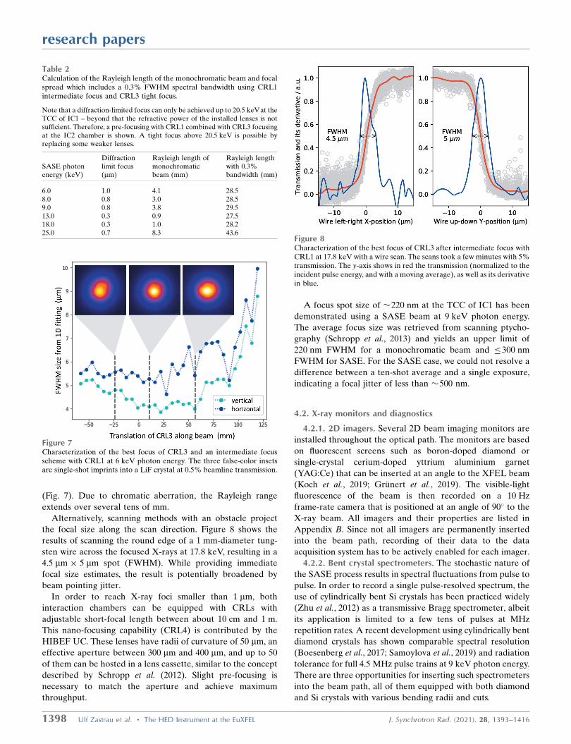
(Fig. 7). Due to chromatic aberration, the Rayleigh range
extends over several tens of mm.
Alternatively, scanning methods with an obstacle project
the focal size along the scan direction. Figure 8 shows the
results of scanning the round edge of a 1 mm-diameter tung-
sten wire across the focused X-rays at 17.8 keV, resulting in a
4.5 mm 5 mm spot (FWHM). While providing immediate
focal size estimates, the result is potentially broadened by
beam pointing jitter.
In order to reach X-ray foci smaller than 1 mm, both
interaction chambers can be equipped with CRLs with
adjustable short-focal length between about 10 cm and 1 m.
This nano-focusing capability (CRL4) is contributed by the
HIBEF UC. These lenses have radii of curvature of 50 mm, an
effective aperture between 300 mm and 400 mm, and up to 50
of them can be hosted in a lens cassette, similar to the concept
described by Schropp et al. (2012). Slight pre-focusing is
necessary to match the aperture and achieve maximum
throughput.
A focus spot size of �220 nm at the TCC of IC1 has been
demonstrated using a SASE beam at 9 keV photon energy.
The average focus size was retrieved from scanning ptycho-
graphy (Schropp et al., 2013) and yields an upper limit of
220 nm FWHM for a monochromatic beam and �300 nm
FWHM for SASE. For the SASE case, we could not resolve a
difference between a ten-shot average and a single exposure,
indicating a focal jitter of less than �500 nm.
4.2. X-ray monitors and diagnostics
4.2.1. 2D imagers. Several 2D beam imaging monitors are
installed throughout the optical path. The monitors are based
on fluorescent screens such as boron-doped diamond or
single-crystal cerium-doped yttrium aluminium garnet
(YAG:Ce) that can be inserted at an angle to the XFEL beam
(Koch et al., 2019; Grunert et al., 2019). The visible-light
fluorescence of the beam is then recorded on a 10 Hz
frame-rate camera that is positioned at an angle of 90� to the
X-ray beam. All imagers and their properties are listed in
Appendix B. Since not all imagers are permanently inserted
into the beam path, recording of their data to the data
acquisition system has to be actively enabled for each imager.
4.2.2. Bent crystal spectrometers. The stochastic nature of
the SASE process results in spectral fluctuations from pulse to
pulse. In order to record a single pulse-resolved spectrum, the
use of cylindrically bent Si crystals has been practiced widely
(Zhu et al., 2012) as a transmissive Bragg spectrometer, albeit
its application is limited to a few tens of pulses at MHz
repetition rates. A recent development using cylindrically bent
diamond crystals has shown comparable spectral resolution
(Boesenberg et al., 2017; Samoylova et al., 2019) and radiation
tolerance for full 4.5 MHz pulse trains at 9 keV photon energy.
There are three opportunities for inserting such spectrometers
into the beam path, all of them equipped with both diamond
and Si crystals with various bending radii and cuts.
research papers
1398 Ulf Zastrau et al. � The HED Instrument at the EuXFEL J. Synchrotron Rad. (2021). 28, 1393–1416
Table 2Calculation of the Rayleigh length of the monochromatic beam and focalspread which includes a 0.3% FWHM spectral bandwidth using CRL1intermediate focus and CRL3 tight focus.
Note that a diffraction-limited focus can only be achieved up to 20.5 keVat theTCC of IC1 – beyond that the refractive power of the installed lenses is notsufficient. Therefore, a pre-focusing with CRL1 combined with CRL3 focusingat the IC2 chamber is shown. A tight focus above 20.5 keV is possible byreplacing some weaker lenses.
SASE photonenergy (keV)
Diffractionlimit focus(mm)
Rayleigh length ofmonochromaticbeam (mm)
Rayleigh lengthwith 0.3%bandwidth (mm)
6.0 1.0 4.1 28.58.0 0.8 3.0 28.59.0 0.8 3.8 29.513.0 0.3 0.9 27.518.0 0.3 1.0 28.225.0 0.7 8.3 43.6
Figure 7Characterization of the best focus of CRL3 and an intermediate focusscheme with CRL1 at 6 keV photon energy. The three false-color insetsare single-shot imprints into a LiF crystal at 0.5% beamline transmission.
Figure 8Characterization of the best focus of CRL3 after intermediate focus withCRL1 at 17.8 keV with a wire scan. The scans took a few minutes with 5%transmission. The y-axis shows in red the transmission (normalized to theincident pulse energy, and with a moving average), as well as its derivativein blue.

Upstream of the sample, the HIREX-II (Kujala et al., 2020)
spectrometer is permanently installed between mirrors M2
and M3. It covers the photon energy range 5–25 keV at a
resolution of �0.2 eV. The reflected signal can either be
recorded with a 10 Hz 2D sCMOS detector, or at 4.5 MHz
with a 1D X-ray GOTTHARD detector (Mozzanica et al.,
2012). For experiments that require the spectral information
right up- or downstream of a sample, additional bent-crystal
spectrometers HED-flex and CNRS-spec can be placed
simultaneously. The CNRS-spec [contribution from Center
National de la Recherche Scientifique (CNRS), France] can
flexibly be placed inside or outside the IC1 chamber, while the
HED-flex can be placed in-air downstream of IC1. Both the
HED- and CNRS-spec are designed to be inserted directly in
the beam, similar to the HIREX-II spectrometer. Both are
also coupled with either a 10 Hz 2D optical camera or a 1D
GOTTHARD X-ray detector. The HED-flex spectrometer
has been tested at 6 keV in the diverging beam (see Fig. 9)
using Si(111) crystal with 78 mm bending radius, and a 10 Hz
ANDOR sCMOS ZYLA 5.5 camera, imaging a 25 mm
YAG:Ce screen, with a magnifying microscope objective. The
minimum energy resolution for this arrangement was 0.13 eV.
A detailed description of the spectrometer configurations
can be found in Appendix B.
4.2.3. Intensity and position monitors. X-ray gas monitors
(XGMs) for non-invasive single-shot pulse energy measure-
ments and average beam postion monitoring are installed
at two positions in the HED beamline (Grunert et al., 2019;
Maltezopoulos et al., 2019; Sorokin et al., 2019). The first
is placed in the XTD1 tunnel, upstream of all optics and
attenuators to measure the output of the undulator. The
second XGM is installed in the HED branch in the XTD6
tunnel after all the main optics. Details on their operation are
described by Maltezopoulos et al. (2019).
Two compact intensity and position monitors (IPMs) are
installed at the HED instrument. The IPM in the HED optics
hutch is positioned downstream of the high-power slit system,
solid attenuators and CRL3 and therefore allows the trans-
mission of these devices to be measured. The second IPM in
the experiment hutch is installed downstream of the differ-
ential pumping system and the clean-up slits. Both devices
insert a thin diamond screen into the beam path and record
the backscattering on four diodes (Hamamatsu S3590-09),
providing pulse-resolved intensities and positions at 4.5 MHz.
The signal difference between the up–down and left–right
diode pairs yields the beam position. For absolute intensity
measurements, the IPMs require cross-calibration to the
XGMs for each specific photon energy. Since the intensity
signal depends on the thickness of the screen, they have less
than 2% thickness variation across the central 5 mm, and less
than 5% over the entire area. Several thicknesses of CVD
diamond screens are available; currently these are 22 mm,
50 mm and 100 mm. Furthermore, the instrument beam stop
(IBS) also incorporates a fast diode monitoring the X-ray
scattering from a permanently installed 500 mm-thick CVD
diamond screen.
4.3. Monochromators
An Si(111) four-bounce monochromator (Dong et al., 2016)
consisting of two pairs of artificial channel-cut crystals can
be inserted into the beam path. It reduces the bandwidth to
�E/E ’ 1 10�4 (Fig. 10) for the complete range of photon
energies. Both pairs of crystals can be cryogenically cooled to
mitigate the heat load during a pulse train. The second pair of
the Si(111)-monochromator can be replaced with a Si(533)
channel-cut crystal, yielding a bandwidth of �E/E ’ 4 10�6
at a fixed photon energy of 7494 eV. More details are given by
Wollenweber et al. (2021). Both configurations provide zero
offset between the incident and the monochromated beam. In
order to keep the beam divergence on the crystals small, the
monochromators are positioned upstream of the CRL2 and
CRL3 optics. The beam jitter after the cryogenically cooled
Si(111) monochromator was measured by the imager screen at
the end of the XTD6 tunnel, 22 m downstream of the mono-
chromator, to be �40 mm in both horizontal and vertical.
4.4. Slit systems
The HED instrument includes three sets of slit systems to
control the size of the beam and its potential halo. Such a halo
can be caused by scattering from upstream slits, apertures,
research papers
J. Synchrotron Rad. (2021). 28, 1393–1416 Ulf Zastrau et al. � The HED Instrument at the EuXFEL 1399
Figure 9Examples of single-pulse spectra. Spectra as recorded by a 2D detectorimaging a scintillator screen (top) and their corresponding lineouts(bottom). Left: HED-flex at 6 keV using a Si(111) crystal and lineouts ofthree different pulses to illustrate the shot-to-shot fluctuation. Right:HIREX-II in the XTD6 tunnel at 17.5 keV using C(110).
Figure 10Measured energy resolution of the Si(111) monochromator at E =6055 eV. The transmitted SASE X-ray pulse energy of the four-bouncesetup is shown as a function of the Bragg angle (scaled to photon energy)of the second pair of crystals while the first pair was fixed. The Gaussianfit yields a FWHM of �E = 0.72 eV and �E/E ’ 1.2 10�4.

screens or filters. The water-cooled power slits are the first
device located in the optics hutch, �15 m upstream of the
TCC in IC1, and this system comprises four independent, non-
intersecting slits with travel ranges of �25 mm. The slits are
5 mm blades of tungsten carbide bonded to an absorbing block
of 70 mm-thick B4C. The blades have highly polished knife-
edges with a slope of 0.5� and can be positioned with an
accuracy of 0.4 mm.
In the experiment hutch�2 m before the TCC of IC1, there
are two sets of clean-up slits, consisting of non-intersecting
blades with travel ranges of �15 mm. These can clean up
potential scattering introduced by the first slit system and the
CRLs. The first pair is similar to the power slit: it uses 4 mm
tungsten carbide blades, with a highly polished 0.5� knife-edge,
mounted to 6 mm-thick B4C absorbers. The second pair,
however, provides a round edge made from Si3N4 and
mounted to a 3 mm tantalum blade. These slits can also be
positioned with an accuracy of <1 mm.
The clean-up slits can also be used to decrease the content
of higher harmonics in the beam, which is typically less
focused near the TCC due to the chromaticity of the CRLs.
4.5. Attenuators and pulse picker
Solid attenuators are placed in the HED beamline at two
positions. The upstream attenuator is positioned in the
common SASE2 branch, downstream of the first XGM and
upstream of the beamline optics (see Fig. 5). It comprises six
chemical vapor deposition (CVD) diamonds (0.075–2.4 mm
thick) and three Si filters (0.5–2.0 mm thick).
The second attenuator at HED is installed just upstream of
the CRL3 optics in the HED optics hutch. Here the filters are
mounted on four motorized arms which hold six attenuators
each. These 24 filters are either Si or CVD diamond with
varying thicknesses (0.025 mm–6.4 mm for Si and 0.1 mm–
1.6 mm for CVD diamond). A wide range of transmissions can
be achieved by the insertion of filters in up to four arms
simultaneously.
The pulse picker unit (PPU) can pick pulse trains at a
maximum repetition rate of 10 Hz. It is positioned just
downstream of the HED XGM and consists of a rotating
chopper disk made from a sandwich of 2 mm B4C and 3 mm
Densimet with several openings across its circumference. This
disk is rotated by a fast DC motor.
5. Drivers
5.1. Intense X-ray pulses
Assuming a typical performance of the SASE2 undulator at
6–10 keV of 2 mJ pulse energy (reduced to �1 mJ at the TCC
due to the overall beamline transmission) in a duration of 25 fs
allows to create power densities, or peak intensities, in excess
of 1017 W cm�2 when focused to 5 mm FWHM. These inten-
sities volumetrically excite solid-density matter at timescales
shorter than a phonon period, and predominantly couple to
certain atomic orbitals when the photon energy is chosen with
respect to resonances or absorption edges (Vinko et al., 2012;
Sperling et al., 2015; Yoneda et al., 2015).
Using the nanofocus setup, the diffraction-limited spot sizes
and resulting intensities for a stack of Be CRLs with radii of
curvature of 50 mm and 300 mm geometric aperture, a mono-
chromatic (seeded) beam at 9 keV, 500 mJ pulse energy
(accounting for the upstream beamline transmission) are as
given in Table 3.
While the achievable intensities are ten times higher than
using CRL3, the excited volume is small and comparable with
the mean free path of photo- and Auger electrons which will
rapidly redistribute the deposited energy. The photon-energy-
dependent transmission can be calculated by equation (48) of
Lengeler et al. (1999) and depends on the absorption prop-
erties of the lens material and the related effective numerical
aperture.
A unique possibility of European XFEL is X-ray excitation
of a sample with a MHz X-ray burst. Free-standing or stati-
cally compressed samples (e.g. in a DAC) can be sequentially
and volumetrically heated and simultaneously probed by
X-ray techniques (cf. Section 7).
While the delay between two subsequent pulses from the
accelerator is limited to 222 ns, in the near future the HED
instrument will also provide two-pulse techniques with
separations <1 ps, either by two-color SASE with an electron
chicane or by using an X-ray split-and-delay line (Mitzner et
al., 2008; Wostmann et al., 2013; Roling et al., 2017; Karcher et
al., 2021).
5.2. Diamond anvil cells
The provision of X-ray photon energies >10 keV enables
the HED instrument to perform experiments in DACs. The
DAC setup in the IC1 chamber is suited for emission spec-
troscopy-type experiments (Section 6.2.6), whereas the one in
IC2 provides a dedicated platform for MHz X-ray diffraction
in dynamic DAC compression and heating experiments
(Sections 6.4 and 6.4.1) which are described in detail by
Liermann et al. (2021). High temperatures (typically in the
range 1000–10000 K) are generated either via double-sided
pulsed laser heating or by X-ray heating, the latter by varying
the repetition rate of the X-ray pulses within a train. Dynamic
compression is achieved in a piezo-driven dynamic DAC
(dDAC) capable of compressing samples to megabar pressures
on a millisecond time scale (Jenei et al., 2019), enabling the
study of material behavior under intermediate strain rates
between those achieved in static and shock compression
experiments. In dynamic, laser-driven shock compression
research papers
1400 Ulf Zastrau et al. � The HED Instrument at the EuXFEL J. Synchrotron Rad. (2021). 28, 1393–1416
Table 3Transmission, diffraction limit and intensity for the nanofocus CRLs.
Transmission(%)
Diffractionlimit (nm)
Intensity(1018 W cm�2)
20 CRLs 50 122 2.130 CRLs 37 89 3.040 CRLs 28 73 3.350 CRLs 22 64 3.4

experiments, DACs can also be used to precompress materials
in order to reach higher pressures at moderate temperatures
which are not accessible by shock-compressing materials from
ambient pressures (Brygoo et al., 2015; Loubeyre et al., 2012).
5.3. Optical lasers
5.3.1. ReLaX laser. The High-intensity Relativistic Laser at
XFEL (ReLaX) is based on a commercial titanium sapphire
laser system manufactured by Amplitude Technologies in
France. The laser architecture follows a double chirped pulse
amplification scheme, with temporal contrast enhancement
using polarization filtering and spectral broadening by cross-
polarized wave generation (XPW). It can deliver up to
300 TW at 5 Hz repetition rate and 100 TW at 10 Hz in
nominal operation mode with pulses as short as 25 fs FWHM.
The wavelength is (800 � 40) nm. The whole laser chain has
been designed with high redundancy of pump lasers and low
fluence due to oversized optics in the compressed beam
transport. The optical compressor, beam transport, and diag-
nostic package have been designed and manufactured through
HIBEF by HZDR. Two loops on the wavefront using a
deformable mirror are employed, one before and one behind
the optical compressor. The commissioning and integration
phase into the HED instrument was successfully completed in
2019. In addition to the main beam of ReLaX, low-energy
probe beams are available, either for optical probing or timing
cross-correlation with X-rays. The unfocused main beam
diameter is 15 cm. Experiments with the ReLaX laser are only
possible in IC1 (see Section 6.2), which is equipped with an
f /# = 2 off-axis parabola as final focusing optics, allowing
multiple sample irradiation geometries, e.g. co-linear, 45� or
normal to the X-ray beam propagation direction. Sending the
uncompressed pulse to IC1 was not foreseen and is currently
technically impossible.
5.3.2. DiPOLE 100-X laser. The High Energy laser DiPOLE
100-X (Diode Pumped Optical Laser for Experiments) is an
all diode-pumped 100 J class ytterbium:YAG based laser,
manufactured by STFC CLF (Central Laser Facility) in the
UK and the University of Oxford as part of the UK’s contri-
bution to the HIBEF UC (Phillips et al., 2019). The laser
system delivers 100 J for a 10 ns pulse duration and 37 J for a
2 ns pulse duration at the fundamental wavelength (1030 nm).
In addition it is capable of 10 Hz operation resulting in kW
output of optical light. Since the main scientific use of
DiPOLE 100-X is laser-driven shock and ramp compression,
the laser provides pulse shaping capabilities with a resolution
of 125 ps, allowing arbitrary waveforms ranging in duration
from 2 to 15 ns. Frequency doubling of the 1030 nm laser to
515 nm with 60 J at 10 Hz for a 10 ns pulse has been demon-
strated using a 60 mm large aperture lithium-triborate (LBO)
crystal (Phillips et al., 2021); conversion efficiencies for a 2 ns
pulse are expected to be similar. The laser is synchronized with
the X-ray beam using the XFEL timing system which has an
RMS jitter of approximately 10 ps. The temporal total
temporal jitter of the laser beam against the X-ray beam
including all components is not yet characterized, but
expected to be better than 50 ps. We also plan an online
monitoring of the arrival time of both laser and X-rays. Phase
plates providing flat-top focal spot profiles ranging from 100 to
500 mm diameter shall be provided. The DIPOLE 100-X laser
will be available in both IC1 and IC2 with irradiation ranging
from close to co-propagation (22.5�) to perpendicular.
The full capabilities of DiPOLE 100-X can be exploited in
combination with the HIBEF-provided VISAR (see Section
6.7.1) system and the high-precision XRD platform at IC2
(see Section 6.4). The DiPOLE 100-X laser was delivered to
European XFEL in 2019 and is currently being commissioned.
The first user experiment is scheduled for 2022. Fig. 11 shows
both the ReLaX and DiPOLE 100-X lasers in the laser bay.
5.3.3. Pump–probe laser. In addition to the HIBEF optical
lasers, the pump–probe (PP) laser, developed at European
XFEL (Palmer et al., 2019), offers intense laser pulses tailored
to the unique time structure of the XFEL bunch pattern. This
laser, which operates with the non-collinear optical parametric
amplifier (NOPA) scheme, has a central wavelength of 800 nm
with a close to Fourier-limited bandwidth for pulses down to
15 fs duration. The laser can deliver synchronized pulses in
10 Hz bursts of up to 600 ms length and an intra-burst
repetition rate up to 4.5 MHz. A maximum pulse energy of
�2 mJ is available at a reduced intra-burst repetition rate
of 100 kHz (Table 4). The pulse duration can be adjusted
research papers
J. Synchrotron Rad. (2021). 28, 1393–1416 Ulf Zastrau et al. � The HED Instrument at the EuXFEL 1401
Table 4Basic specifications of the pump–probe laser.
Name Central wavelength (nm) Repetition rate Pulse duration (FWHM)
Mode 1 (NOPA) 800 100 kHz @ 2 mJ 15–300 fs nearly transform limited4.5 MHz @ 0.05 mJ
Mode 2 (amplifier for NOPA) 1030 100 kHz @ 35 mJ, 0.9 ps (compressed), 500 ps (chirped)4.5 MHz @ 1 mJ
Figure 11View into the HED laser bay with both HIBEF high-power lasersDIPOLE 100-X (left) and ReLaX (right).

between 15 and 300 fs FWHM via bandwidth management
while remaining close to the Fourier limit (no chirp). The PP
laser is operational since 2020. Currently, the laser is operated
with a single pulse energy of around 1 mJ with 100 kHz
repetition rate and pulse duration of 17 fs FWHM. The second
harmonic generation (SHG, � = 400 nm) is also available. The
conversion efficiency to SHG is only about 15% at 15 fs
operation due to its large spectral bandwidth. In addition, the
pump laser for the NOPA can be delivered to experiments
upon request. This laser has a fundamental wavelength of
1030 nm with �2 nm bandwidth which results in �1 ps pulse
duration, or �500 ps in chirped mode. This operation mode is
particularly interesting for applications which require higher
single pulse energies of up to 35 mJ.
5.3.4. Synchronization of optical lasers and XFEL pulses.The optical lasers ReLaX, DiPOLE, and PP require spatial
and temporal synchronization with the X-ray pulses which
places high demands on environmental stability and an
extensive online diagnostics. The linear accelerator provides
pulses according to its own timing, and the various laser
sources need to be synchronized relative to it. When lasers are
synchronized using the accelerator’s radiofrequency only, a
jitter of about 300 fs is observed (Kirkwood et al., 2019). To
improve on this, a Master-Laser-Oscillator (MLO) provides
a more stable timing reference. A dispersion-compensated,
actively stabilized optical fiber link synchronizes the individual
oscillators of the ReLaX and PP laser on a sub-10 fs level.
Nevertheless, the subsequent amplification process in both the
FEL and the optical lasers and their long beam transport will
lead to additional timing jitter and long-term temporal drift.
Therefore, a pulse-resolved online photon arrival monitor
(PAM) is implemented to record the relative arrival time
between the optical and the X-ray pulses at the 10 Hz repe-
tition rate. The PAM is permanently installed about 10 m
upstream of the IC1 sample position in the optics hutch,
before the X-ray attenuator and CRL3. This allows the jitter
measurements to be quasi-independent from the X-ray
focusing scheme and attenuation level which may be varied
during experiments. The obtained data can be later used for
time-sorting and binning. The typical sample is Si3N4 with
2 mm thickness. This ensures a high X-ray transmittance
(>90% at >5 keV and >97% at >8 keV) for experiments
downstream. The PAM consists of two sample chambers which
allows simultaneous measurements using spatial (Harmand et
al., 2013; Riedel et al., 2013) and spectral encoding (Bionta et
al., 2011) (Fig. 12) methods. While spatial encoding provides a
better signal-to-noise ratio, the spectral encoding appears to
be more robust against X-ray pointing fluctuations. To ensure
that PAM works at different X-ray photon energies, Si3N4 of
4 and 6 mm thickness and a high-Z material sample (e.g.
YAG:Ce 10, 20 mm thicknesses) are available, and are inter-
changeable during experiments.
The arrival timing jitter between the X-ray and the PP laser
on PAM was measured to be 20–30 fs RMS.
5.4. Pulsed magnet
In 2021, the HIBEF UC will install a 750 kJ capacitor bank
with a peak current of 100 kA and pulsed magnets in different
geometries: a horizontal bi-conical 60�–20� solenoid with peak
fields of 60 T, and a split-coil (30 T) for diffraction experi-
ments exploiting the full equatorial plane. Both coil systems
integrate an eddy current shield in order to minimize stray
fields and resulting vibrations due to interactions with the
environment. The coils are cooled by liquid-nitrogen bath
cryostats and the sample cryostat provides temperatures
between 4 K and 600 K. The current design of the pulsed
magnet setup represents a separate experimental platform
optimized for peak field strengths and cryogenic temperatures.
Thus, it cannot be used in conjunction with other drivers such
as DACs or optical lasers. Furthermore, development of a
phase retarder to control the polarization of the incident
X-ray beam and of the polarization analyser for the scattered
X-rays is currently ongoing.
6. Experimental platforms
6.1. Experimental hutch layout
The experiment hutch enclosure is constructed from up to
100 cm-thick heavy concrete walls, to anticipate the radiation
and particles generated from the intense optical laser–matter
interaction (e.g. using the ReLaX laser) and has been designed
based on FLUKA simulations (Nakatsutsumi & Tschentscher,
2013; Battistoni et al., 2015). Transport of large equipment in
and out of the hutch is possible through a 3 m-wide by 2.5 m-
high sliding door.
The floor plan of the 4 m-high HED experiment hutch is
shown in Fig. 13, and the X-ray beam path is 1400 mm above
the hutch floor. The hutch is organized in two interaction areas
(IAs): the X-rays enter IA1 by passing through a differential
pumping section into the fixed interaction chamber (IC) 1 (see
Section 6.2) and then proceed to IA2. All drivers except the
pulsed magnet can be brought to the IC1 chamber. Further-
more, the ReLaX (Section 5.3.1) and DiPOLE (Section 5.3.2)
laser beams are brought into the experiment hutch from the
laboratory on the top floor through chicanes in the roof. On
research papers
1402 Ulf Zastrau et al. � The HED Instrument at the EuXFEL J. Synchrotron Rad. (2021). 28, 1393–1416
Figure 12Typical images of PAM. (a) Spatial encoding: vertical versus horizontalposition; time mapping results form an angle between the laser and the X-ray on the sample (2 mm-thick Si3N4). The temporal window (horizontal)is about 3.6 ps. (b) Spectral encoding image: lateral position versus thewavelength mapped to time by a chirped laser pulse collinear with theX-ray perpendicular to the sample (100 mm-thick YAG:Ce). Thetemporal window (horizontal axis of the image) is about 1.7 ps. Bothshow a shadow due to the X-ray-induced opacity change of the sample.At t0 both beams are timed. The horizontal edges in (a) result from theupstream partially closed power slits which are not influencing (b).

either side of the IC1 chamber are optical tables for optical
laser diagnostics and optical sample diagnostics such as
VISAR (Section 6.7.1).
The IA2 allows for various dedicated setups. Here, the IC2
chamber (Section 6.4) is permanently mounted on a rail
system, which is embedded in the hutch floor, and can be
brought into the beam, or parked by the wall. In the near
future, IA2 will also host a goniometer for pulsed magnetic
field experiments.
Downstream of IC1, rails run parallel to the X-ray beam
path, carrying a 3 m-wide detector bench. It can be located at
any position between the rear end of IC1 and the beam stop at
the hutch wall. The bench is optimized to minimize vibrations
and equipped with spectrometers and detectors including
VAREX or AGIPD (see Sections 6.4.4 and 6.4.3).
The standards for vacuum in the experiment chambers
require clean conditions at <10�4 mbar pressure (Schmidt &
Dommach, 2015). This volume is decoupled from the ultra-
high vacuum in the optics hutch and tunnels (�10�9 mbar) by
a differential pumping stage (DPS) which allows window-less
X-ray operation. However, if the experiment requires ambient
pressure, gate valves before IC1 and IC2 can be used to
separate the chambers which are equipped with a 10 mm-
diameter, 100 mm-thick diamond window with excellent X-ray
transmission.
6.2. Interaction chamber 1
IC1 is a large multi-purpose chamber, manufactured by
TOYAMA. All laser drivers, a manifold of sample geometries,
spectrometers and other diagnostics can be arranged in
vacuum around the X-ray beam at the TCC. The chamber
body is made from an Al alloy to avoid long-duration nuclear
activation during laser-plasma experiments which could
interrupt user operation. Perpendicular to the X-ray path,
large hinged doors allow easy access. The primary access doors
open into a clean tent providing a flow of filtered air.
As the X-rays at European XFEL are horizontally polar-
ized, scattering is preferably measured in the vertical plane
where the scattered signal is not reduced by polarization
effects. Therefore IC1 provides a vertical breadboard with
motorized rails in the shape of circular arcs with the TCC in
their centers (see Fig. 14). The arc radii are R = 306, 517 and
750 mm. Onto these, motorized carriages are mounted which
can hold detectors and spectrometers of several kg weight.
A central target mount and a horizontal breadboard are
mechanically decoupled from each other and the vacuum
chamber itself, and rest on separate granite supports. The
dimensions of the horizontal breadboard are 2.3 m 1.4 m,
and the X-ray beam is (349 � 1) mm above its surface. It
research papers
J. Synchrotron Rad. (2021). 28, 1393–1416 Ulf Zastrau et al. � The HED Instrument at the EuXFEL 1403
Figure 14(a) Cut through the schematic of the IC1 target chamber showing thevertical breadboard with circular rails. (b) Top view of the interior of IC1;the access doors are at the bottom. In red, a typical beam path for theReLaX laser is shown, and the back line indicates a sample viewingsystem. The beam transport of the DiPOLE-100X high-energy laser inIC1 is flexible and customized configurations are currently evaluated.
Figure 13Floor plan of HED experiment hutch with the positions of IC1 (right,rectangular), IC2 (center, round) and the AGIPD on the detector benchon the left. The XFEL beam enters from the right. The dark-gray areasindicate hutch infrastructure, while the orange areas mark access paths.Dimensions are given in millimetres.
provides M6 threaded holes in a 25 mm pattern. The IC1
walls are equipped with multiple feedthroughs with Japanese
Industry Standards (JIS), ISO-K, and KF standards. On the
roof of IC1, six turbomolecular pumps (HIPACE 800, Pfeiffer)
with a pumping power of 790 l s�1 (for N2) pump the chamber
through two large gate valves to <10�5 mbar.
6.2.1. Sample tower. In the center of IC1, an electrically
and mechanically insulated sample tower consists of (from top
to bottom): horizontal and vertical linear stages (Fast Sample
Scanner), Hexapod (H-824, Physik Instrumente), 360� rota-
tion stage (Goniometer 411, Huber Diffraktionstechnik), and
a linear Y-axis (height) stage. It is possible to remove the Fast
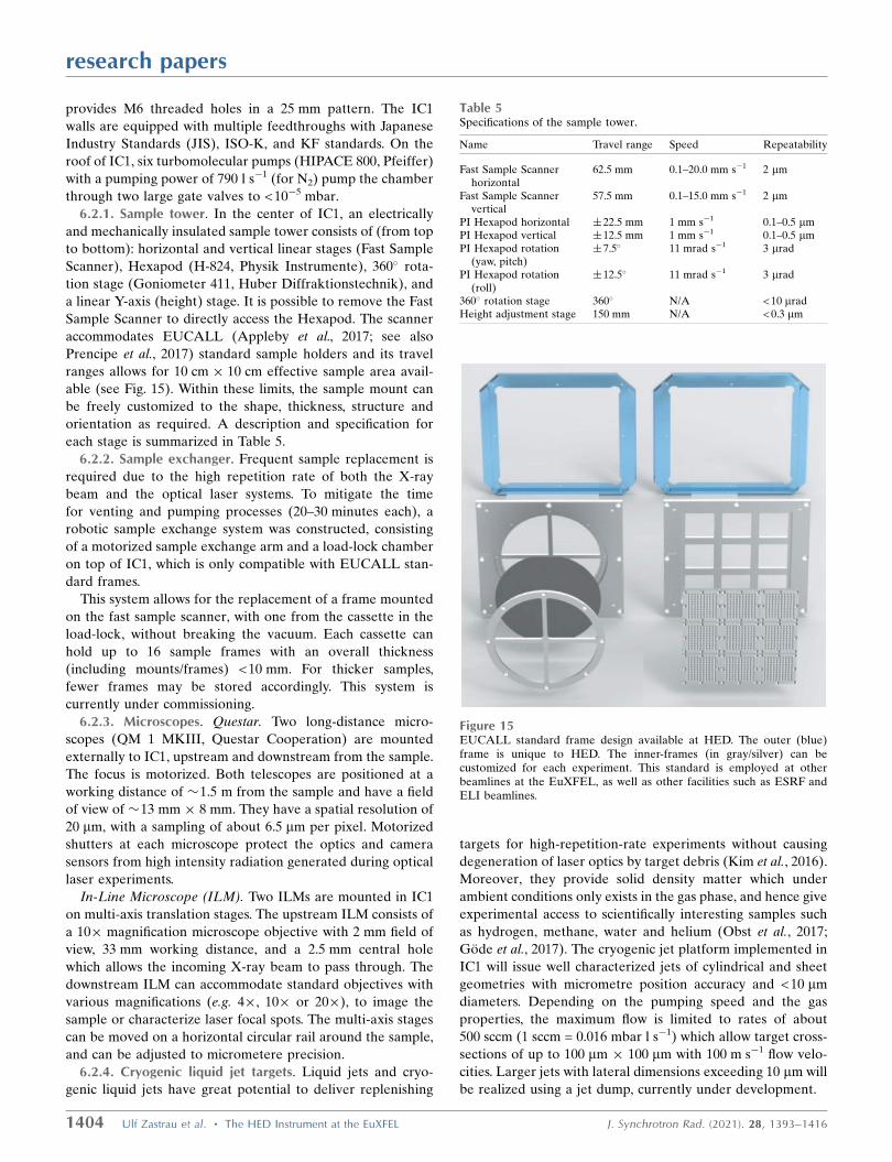
Sample Scanner to directly access the Hexapod. The scanner
accommodates EUCALL (Appleby et al., 2017; see also
Prencipe et al., 2017) standard sample holders and its travel
ranges allows for 10 cm 10 cm effective sample area avail-
able (see Fig. 15). Within these limits, the sample mount can
be freely customized to the shape, thickness, structure and
orientation as required. A description and specification for
each stage is summarized in Table 5.
6.2.2. Sample exchanger. Frequent sample replacement is
required due to the high repetition rate of both the X-ray
beam and the optical laser systems. To mitigate the time
for venting and pumping processes (20–30 minutes each), a
robotic sample exchange system was constructed, consisting
of a motorized sample exchange arm and a load-lock chamber
on top of IC1, which is only compatible with EUCALL stan-
dard frames.
This system allows for the replacement of a frame mounted
on the fast sample scanner, with one from the cassette in the
load-lock, without breaking the vacuum. Each cassette can
hold up to 16 sample frames with an overall thickness
(including mounts/frames) <10 mm. For thicker samples,
fewer frames may be stored accordingly. This system is
currently under commissioning.
6.2.3. Microscopes. Questar. Two long-distance micro-
scopes (QM 1 MKIII, Questar Cooperation) are mounted
externally to IC1, upstream and downstream from the sample.
The focus is motorized. Both telescopes are positioned at a
working distance of �1.5 m from the sample and have a field
of view of �13 mm 8 mm. They have a spatial resolution of
20 mm, with a sampling of about 6.5 mm per pixel. Motorized
shutters at each microscope protect the optics and camera
sensors from high intensity radiation generated during optical
laser experiments.
In-Line Microscope (ILM). Two ILMs are mounted in IC1
on multi-axis translation stages. The upstream ILM consists of
a 10 magnification microscope objective with 2 mm field of
view, 33 mm working distance, and a 2.5 mm central hole
which allows the incoming X-ray beam to pass through. The
downstream ILM can accommodate standard objectives with
various magnifications (e.g. 4, 10 or 20), to image the
sample or characterize laser focal spots. The multi-axis stages
can be moved on a horizontal circular rail around the sample,
and can be adjusted to micrometere precision.
6.2.4. Cryogenic liquid jet targets. Liquid jets and cryo-
genic liquid jets have great potential to deliver replenishing
targets for high-repetition-rate experiments without causing
degeneration of laser optics by target debris (Kim et al., 2016).
Moreover, they provide solid density matter which under
ambient conditions only exists in the gas phase, and hence give
experimental access to scientifically interesting samples such
as hydrogen, methane, water and helium (Obst et al., 2017;
Gode et al., 2017). The cryogenic jet platform implemented in
IC1 will issue well characterized jets of cylindrical and sheet
geometries with micrometre position accuracy and <10 mm
diameters. Depending on the pumping speed and the gas
properties, the maximum flow is limited to rates of about
500 sccm (1 sccm = 0.016 mbar l s�1) which allow target cross-
sections of up to 100 mm 100 mm with 100 m s�1 flow velo-
cities. Larger jets with lateral dimensions exceeding 10 mm will
be realized using a jet dump, currently under development.
research papers
1404 Ulf Zastrau et al. � The HED Instrument at the EuXFEL J. Synchrotron Rad. (2021). 28, 1393–1416
Table 5Specifications of the sample tower.
Name Travel range Speed Repeatability
Fast Sample Scannerhorizontal
62.5 mm 0.1–20.0 mm s�1 2 mm
Fast Sample Scannervertical
57.5 mm 0.1–15.0 mm s�1 2 mm
PI Hexapod horizontal �22.5 mm 1 mm s�1 0.1–0.5 mmPI Hexapod vertical �12.5 mm 1 mm s�1 0.1–0.5 mmPI Hexapod rotation
(yaw, pitch)�7.5� 11 mrad s�1 3 mrad
PI Hexapod rotation(roll)
�12.5� 11 mrad s�1 3 mrad
360� rotation stage 360� N/A < 10 mradHeight adjustment stage 150 mm N/A < 0.3 mm
Figure 15EUCALL standard frame design available at HED. The outer (blue)frame is unique to HED. The inner-frames (in gray/silver) can becustomized for each experiment. This standard is employed at otherbeamlines at the EuXFEL, as well as other facilities such as ESRF andELI beamlines.

6.2.5. X-ray spectrometers. Spectroscopy applications
studying extreme states require vacuum conditions and suffi-
cient flexibility for excitation methods and setup of the various
technique-dependent spectrometers. In IC1, X-ray Emission
Spectroscopy (XES) and Inelastic X-ray Scattering (IXS),
both for meV and eV resolution, are provided. For in-vacuum
use in IC1, we have designed highly efficient spectrometers
(Preston et al., 2020) using cylindrical mosaic crystals in
von Hamos geometry (von Hamos, 1934). Highly Annealed
Pyrolytic Graphite (HAPG) crystals (Zastrau et al., 2013) with
thicknesses of 40 mm or 100 mm or Highly Oriented Pyrolitic
Graphite (HOPG) (Zastrau et al., 2012) with thickness 100 mm
can be used, with radii of 50 mm or 80 mm. The spectrometer
is designed to use either an ePix100 or Jungfrau detector. The
HAPG crystals have demonstrated (Preston et al., 2020) to
reach resolving powers of E/�E � 2800 at photon energies
between 5 and 10 keV. An example spectrum of Cr K� is
shown in Fig. 16. Fig. 17 shows these spectrometers mounted
in IC1, together with three diced analyzers (see below).
Furthermore, in conjunction with the aforementioned high-
resolution Si(533) monochromator (see Section 4.3), several
diced analyzer crystals can be coupled with a detector to
provide 40 meV spectral resolution at 7495 eV. As shown in
Fig. 18, this is sufficient to resolve inelastic X-ray scattering
from phonons in solids, or ion-acoustic waves in plasmas
(Wollenweber et al., 2021; Descamps et al., 2020).
6.2.6. Diamond anvil cell platform in IC1. The DAC setup
in IC1 is built for MHz spectroscopy at high pressure and
temperatures. While static high pressures are generated by the
DAC itself, high temperatures in IC1 are achieved via X-ray
heating, by varying the repetition rate or intensity of the X-ray
pulses within a MHz pulse train. Future developments of this
experimental platform may include temperature measure-
ments by optical diagnostics such as the portable system with
streaked optical pyrometry (Section 6.7.2) and/or multi-color
pyrometry (von Hamos, 1934). The X-ray spectrometer has
been designed, built and contributed by the University of
Dortmund, and is tailored for emission from matter contained
in a diamond anvil cell. It comprises four vertically stacked
analyzer crystals of either Si(111) or Si(531) with a radius of
curvature of 250 mm and a size of 110 mm 20 mm, covering
an energy range of 6–8 keV with a resolution of 0.3–0.4 eV
(Klementiev & Chernikov, 2020).
6.3. Small X-ray detectors
The HED instrument is offering compact and vacuum
compatible X-ray detectors. All detectors are suitable for
X-ray diffraction, and can be used in conjunction with the
aforementioned spectrometers. They can be positioned inside
research papers
J. Synchrotron Rad. (2021). 28, 1393–1416 Ulf Zastrau et al. � The HED Instrument at the EuXFEL 1405
Figure 173D schematics of up- and downstream HAPG spectrometers and threediced analyzers mounted on the curved rail system in IC1, leaving thehorizontal breadboard free for laser optics and further instrumentation.
Figure 18The spectra of the Si(533)-monochromated beam scattered from PMMA(elastic, blue) and single crystal diamond (inelastic, red) resolved with adiced Si (533) analyzer crystal. For better comparison, the elastic signal isreduced by a factor of ten. For diamond, the peaks correspond to phononcreation and annihilation. The spectrum is reproduced from Wollenweberet al. (2021).
Figure 16K� fluorescence of a 5 mm Cr foil irradiated by an 10 mm X-ray FEL spotfor calibration purposes (black-dashed) with fit (red). The spectralbroadening of the lines by the 80 mm radius-of-curvature and 40 mm-thick HAPG crystal is �2 eV. Reproduced from Preston et al. (2020).

IC1 using the vertical breadboard and motorized translation
systems. In air, the detector bench in IA2 can be used to
achieve larger sample–detector distances of up to 7 m for
small-angle X-ray scatting (SAXS), radiography, or phase
contrast imaging (PCI).
The detectors inside IC1 are the ePix100 (Blaj et al., 2016;
Klackova et al., 2019), ePix100H hammerhead (Blaj et al.,
2019), and the Jungfrau (Mozzanica et al., 2018). Their speci-
fications are summarized in Table 6. The HED instrument
currently offers two vacuum-compatible ePix100 modules to
users, while two more modules with hammerhead sensors are
foreseen. A dedicated air-box housing developed at European
XFEL (Fig. 19) enables also the Jungfrau detector to be
operated in vacuum. The Jungfrau features automatic gain
switching of each pixel which allows detection of single photon
events and high signal levels of up to 10000 12 keV photons in
a single image (Redford et al., 2018, 2020). In total, four single
Jungfrau modules are available and two modules can be
combined into a larger detector with sensor size 2048 516 or
1024 1024 pixels with an inter-modular gap of 4.5 mm and
2.5 mm, respectively.
6.4. Interaction chamber 2
IC2 [Fig. 20(a)] is optimized for diffraction experiments,
exploiting the high photon energies and MHz time structure of
the X-rays for the study of materials under extreme pressures,
temperatures and strain rates. It hosts two experimental
platforms: one for DAC experiments
[Fig. 20(b)], and one for dynamic laser
compression experiments using the
DiPOLE 100-X laser (Fig. 21).
The IC2 chamber has an outer
diameter of 1360 mm and a height of
1520 mm. Further details are given by
Liermann et al. (2021). The chamber is
located in IA2 and can be moved
between the operating and parking position on a rail system.
The vacuum system allows for turnaround times below
30 minutes including venting, pumping and sample exchanges.
IC2 can be coupled with either of two detector systems: the
AGIPD 1M detector (Section 6.4.3), designed to resolve
individual pulses at the minimum bunch spacing of the X-ray
at 222 ns, and a twin configuration of two Varex flat-panel
detectors (Section 6.4.4) for maximum gapless coverage at
10 Hz repetition rate in an EMP- and debris-resistant housing.
6.4.1. Diamond anvil cell platform in IC2. This DAC plat-
form [Fig. 20(b)] is designed to explore MHz diffraction for
X-ray heating, pulsed laser heating, and dynamic compression
experiments using piezoelectric drivers. A sample stack
provides all motorizations that are required to align a DAC in
the center of rotation, relative to the detector and X-ray beam.
Stability and resolution were optimized for studies of micro-
metre-sized samples with beam sizes down to 100 nm. Up to
six conventional or three dynamic DACs can be mounted on
carousel type sample exchangers. The DAC platform can
be combined with a double-sided laser-heating setup which
integrates sample observation, near infrared pulsed laser
heating, and streaked optical pyrometry in a coaxial design.
The addition of a four-channel multi-color spectrometer for
fast, high-sensitivity pyrometry is planned.
6.4.2. Dynamic laser compression platform. The dynamic
laser compression platform was conceived for maximum
flexibility in the geometry between the DiPOLE laser, VISAR
diagnostics (Section 6.7.1), and X-ray diffraction (Fig. 21). The
sample stack was build around the EUCALL sample frame
system. In addition, it features mounting interfaces for user-
research papers
1406 Ulf Zastrau et al. � The HED Instrument at the EuXFEL J. Synchrotron Rad. (2021). 28, 1393–1416
Figure 19Model of the Jungfrau detector in an air-box, developed at the HEDInstrument for in-vacuum operation.
Table 6Detector specifications available at IC1.
Detectorname
Pixel size(mm)
Noise(adu)
Gain(eV adu�1) Dynamic range
Sensor size(pixels)
ePix100 50 50 < 4 54 100 photons @ 8 keV 704 768ePix100H 25 100 < 4 54 100 photons @ 8 keV 176 1536Jungfrau 75 75 < 15 20 104 photons @ 12 keV 512 1024
Figure 20Interaction chamber IC2. (a) Vacuum chamber. (b) Platform for high-pressure research with diamond anvil cells.
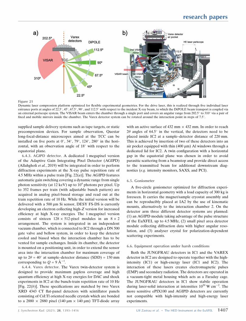
supplied sample delivery systems such as tape targets, or static
precompression devices. For sample observation, Questar
long-focal-distance microscopes aimed at the TCC can be
installed on five ports at 0�, 34�, 79�, 124�, 280� in the hori-
zontal, with an observation angle of 18� with respect to the
equatorial plane.
6.4.3. AGIPD detector. A dedicated 1 megapixel version
of the Adaptive Gain Integrating Pixel Detector (AGIPD)
(Allahgholi et al., 2019) will be integrated in order to perform
diffraction experiments at the X-ray pulse repetition rate of
4.5 MHz within a pulse train [Fig. 22(a)]. The AGIPD features
automatic gain switching covering a dynamic range from single
photon sensitivity (at 12 keV) up to 104 photons per pixel. Up
to 352 frames per train (with adjustable bunch pattern) are
acquired in analog pixel-based storage and read out at the
train repetition rate of 10 Hz. While the initial version will be
delivered with a 500 mm Si sensor, DESY FS-DS is currently
developing an electron collecting high-Z version for increased
efficiency at high X-ray energies. The 1 megapixel version
consists of sixteen 128 512-pixel modules in an 8 2
arrangement. The system is integrated in an independent
vacuum chamber, which is connected to IC2 through a DN 500
gate valve and bellow system, in order to keep the detector
cooled and biased when the interaction chamber has to be
vented for sample exchanges. Inside its chamber, the detector
is mounted on a positioning unit, in order to extend the sensor
area into the interaction chamber for maximum coverage of
up to 2� = 40� at sample–detector distance (SDD) = 150 mm
corresponding to Q = 9 A�1.
6.4.4. Varex detector. The Varex twin-detector system is
designed to provide maximum gapless coverage and high
quantum efficiency at high X-ray energies for DAC and shock
experiments in IC2 at the bunch-train repetition rate of 10 Hz
[Fig. 22(b)]. These specifications are matched by two Varex
XRD 4343 CT flat-panel detectors with scintillator panels
consisting of CsI:Tl oriented needle crystals which are bonded
to a 2880 2880 pixel (140 mm 140 mm) TFT-diode array
with an active surface of 432 mm 432 mm. In order to reach
2� angles of 64.5� in the vertical, the detectors need to be
placed inside IC2 at a sample–detector distance of 220 mm.
This is achieved by insertion of two of these detectors into an
air pocket equipped with thin (400 mm) Al windows through a
dedicated lid for IC2. A twin configuration with a horizontal
gap in the equatorial plane was chosen in order to avoid
parasitic scattering from a beamstop and provide direct access
to the transmitted beam for additional downstream diag-
nostics (e.g. intensity monitors, SAXS, and PCI).
6.5. Goniometer
A five-circle goniometer optimized for diffraction experi-
ments in horizontal geometry with a load capacity of 300 kg is
foreseen. It carries the magnet/sample cryostat assembly and
can be reproducibly placed at IA2 by the use of kinematic
mounts, alternatively to the interaction chamber 2. On the
detector arm three different detector systems are planned:
(1) an AGIPD module taking advantage of the pulse structure
of the EuXFEL up to 4.5 MHz, (2) small pixel area detector
module collecting diffraction data with higher angular reso-
lution, and (3) analyser crystal for polarization-dependent
scattering experiments.
6.6. Equipment operation under harsh conditions
Both the JUNGFRAU detectors in IC1 and the VAREX
detector in IC2 are designed to operate together with the high-
intensity (IC1) or high-energy laser (IC1 and IC2). The
interaction of these lasers creates electromagnetic pulses
(EMP) and secondary radiation. The detectors are operated in
a vacuum-tight metal housing which acts as a Faraday cage.
The JUNGFRAU detectors in IC1 show stabile operation
during laser-solid interaction at intensities 1020 W cm�2. The
more sensitive ePIX100 and AGIPD detectors are currently
not compatible with high-intensity and high-energy laser
experiments.
research papers
J. Synchrotron Rad. (2021). 28, 1393–1416 Ulf Zastrau et al. � The HED Instrument at the EuXFEL 1407
Figure 21Dynamic laser compression platform optimized for flexible experimental geometries. For the drive laser, this is realized through five individual laserentrance ports at angles of 22.5�, 45�, 67.5�, 90�, and 112.5� with respect to the incident X-ray beam, to which the DiPOLE beam transport is coupled viaan external periscope system. The VISAR beam enters the chamber through a single port and covers an angular range from 202.5� to 310� via a pair offixed and mobile mirrors inside the chamber. The Varex detector system can be rotated around the interaction point in steps of 7.5�.

6.7. Optical diagnostics
In order to characterize the macroscopic state of dynami-
cally compressed or excited matter, several optical diagnostics
developed for the investigation of laser–matter interactions
have been implemented. This is important for two reasons.
First, the microscopic behavior of matter measured with
X-rays can be related to macroscopic properties. Second, these
diagnostics can measure the macroscopic evolution of the
material over a large temporal and spatial scale, thus relating
the point in time measurement of the X-rays with, for
example, the compression history of a sample.
6.7.1. Velocity Interferometer System for Any Reflector –VISAR. In order to characterize laser-shocked samples, the
HIBEF UC has contributed a VISAR system (Barker &
Hollenbach, 1965). VISAR enables the measurement of shock
or interface velocities ranging from less than 100 m s�1 to
above 50 km s�1 with a temporal resolution better than 10 ps.
The VISAR system has in total three parallel arms to cover
a wide range of detectable velocities which can range from
0.3 km s�1 fringe�1 to 40 km s�1 fringe�1. Two arms operate
at 532 nm and one at 1064 nm, permitting the simultaneous
measurement of reflectivities at two different wavelengths.
The system is able to record temporal windows as long as 50 ns
and can adapt the field of view from 250 mm to 2 mm whilst
keeping the full F/2.5 numerical aperture of the optical
system.
The VISAR is available in both IC1 and IC2; the beam path
from IC2 to the VISAR system is routed through IC1. In IC1,
similar optics as in IC2 will be used to pick up the reflection
from the target surface and thus allow to use the same VISAR
system for experiments in IC1.
6.7.2. Streaked Optical Pyrometry – SOP. Streaked Optical
Pyrometry (SOP) is an instrument to deduce the temperature
of a sample by analysing its emitted optical radiation. The
temperature is either deduced from fitting the spectral inten-
sity distribution to gray body radiation or the absolute
radiation intensity at a given wavelength. The latter method
has higher sensitivity and provides spatial information but
requires a reflectance measurement, which can be provided
by the VISAR system. Using a streak camera as a detector
permits recording the temperature of the sample over time
spans ranging from 1 ns to 100 ms with the possibility of sub-ns
temporal resolution. The SOP system can be used in both
interaction areas for various experiments such as pulsed laser
heating, shock compression or isochoric heating.
research papers
1408 Ulf Zastrau et al. � The HED Instrument at the EuXFEL J. Synchrotron Rad. (2021). 28, 1393–1416
Figure 22(a) HIBEF AGIPD 1M detector and coverage as a function of X-ray energy. (b) Varex twin detector system and coverage as a function of X-ray energyfor the downstream position.

The SOP system specifically designed for IC2 detects
thermal or fluorescence radiation emitted from the interaction
of the XFEL pulses with a DAC sample, or during pulsed laser
heating. The system features a HAMAMATSU streak camera
with S-20 photocathode coupled to an optical spectrometer. It
is placed outside the IC2, along with optics for high magnifi-
cation microscopes for DAC sample observation, illumination,
filtering and alignment. The spectral range for the optical
spectrometer covers 440–850 nm.
6.7.3. Fourier Domain Interferometry – FDI. Fourier-
domain interferometry (FDI) (Geindre et al., 1994) enables
the measurement of polarization-resolved reflectivity, phase
shifts in the reflected probe due to plasma expansion or due to
changes in refractive index via electronic excitation. The HED
FDI system is available to users and consists of a 1 :1 imaging
spectrometer with an upstream Mach-Zehnder inter-
ferometer. It allows to measure the velocity of the critical
density surface with �10 nm and a few 100 fs resolution in a
�10 ps temporal window.
7. Methods and experiments
The HED instrument supports a variety of ultrafast X-ray
methods as summarized in Appendix A. XRD can be realized
by positioning in-vacuum detectors in IC1 at the required
geometry to cover dedicated scattering angular ranges.
Designed for precision diffraction, IC2 provides larger
detectors in forward-scattering, which in combination with
hard X-rays allows radial patterns for particle distribution
functions or texture analysis to be recorded.
In general, IC1 with its larger volume and two breadboards
is optimized for spectroscopic applications. The HAPG spec-
trometers (Section 6.2.5) can be used for both XES and IXS.
We also provide perfect crystals for a dedicated von Hamos
analyzer for measuring K-shell emission
from the 3d transition metals Cr, Mn,
Fe, Co, Ni, Cu and Zn. The spectro-
meter can be combined with a DAC
sample environment and isochoric
X-ray heating, which opens up the
unique possibility to probe the elec-
tronic state at high pressures and
temperatures of solid and liquid
materials, e.g. that are of geological
relevance.
X-ray imaging is achieved by placing
a nanometre X-ray focus upstream of
the sample (by using the nanofocusing
CRL4) and an on-axis projection onto
a detector. The distance to the target
needs to be sufficiently large for
magnified PCI with high spatial resolu-
tion. The imaging performance depends
also on several other parameters such as
X-ray wavelength, focus and feature
size, and sample properties (Schropp et
al., 2015; Hagemann et al., 2021). Both
IC1 and IC2 qualify for PCI; however, IC1 allows for more
propagation between sample and detector.
In order to illustrate the capabilities of the HED instru-
ment, we highlight a few showcase experiments.
7.1. X-ray heating in DACs
Increasing the temperature in samples under pressure solely
by exposing them to the MHz X-ray pulse train (Meza-Galvez
et al., 2020) is an interesting alternative to the resistive or
laser-heated DAC experiments (Spiekermann et al., 2020)
because of the possibility to suppress chemical reactions and
contamination of the sample from the diamond anvils. High-
precision diffraction experiments IC2 coupled with simulta-
neous SOP provided the temperature evolution and verified
sample stability. The DAC assembly proved to be robust in the
XFEL beam, which will in future enable novel pulse-resolved
diffraction experiments at extreme conditions including high
strain rates using MHz detectors.
Recently, Hwang et al. (2021) observed the ultrafast
synthesis of "-Fe3N1+x in a DAC from Fe and N2 under pres-
sure using serial exposures of 17.8 keV pulses, using the IC2
DAC platform. When the sample at 5 GPa was irradiated by
a pulse train separated by 443 ns (2.2 MHz), the estimated
sample temperature at the delay time was above 1400 K,
confirmed by in situ transformation of �- to �-iron (Fig. 23).
7.2. Combined spectroscopy and diffraction experimentsin DACs
Differently to IC2, the DAC setup in IC1 was used in a
number of measurements that combined emission spectro-
scopy [at the Fe-emission lines (Lin et al., 2005)] and X-ray
diffraction at 13 keV incident XFEL photon energy. The goal
of the experiment was to study simultaneously the structure
research papers
J. Synchrotron Rad. (2021). 28, 1393–1416 Ulf Zastrau et al. � The HED Instrument at the EuXFEL 1409
Figure 23The changes of X-ray diffraction patterns of iron and nitrogen during in situ chemical reaction byXFEL pump-and-probe. An Fe foil surrounded by N2 was pre-compressed to 5 GPa in a DAC. Thepercentages in run A indicate the transmission (fluence) of the XFEL. At 100% XFEL transmission,run B contains 20 consecutive pulses while run C has consecutive pulses over 11 s. For more detailsand figure credit, refer to Hwang et al. (2021).

and electronic configuration of Fe-bearing compounds at
extreme pressures and temperatures in situ. While under
pressure, the sample was subjected to trains of several X-ray
pulses which step-wise heated the sample in the DAC. During
this temperature increase, the sample undergoes a spin cross-
over (Cerantola et al., 2015), which was detected both in
diffraction and emission signals.
7.3. Laser shock compression experiments on planetarymaterials
Geodynamic models of planetary interiors depend on the
precise knowledge of the equation of state and the high-
pressure phase diagram of materials such as SiO2 and MgO.
Previous studies demonstrated in shock compression experi-
ments that these materials can transition from electrically
insulating solids to conducting liquids at ultra-high pressures
(Umemoto et al., 2006; Millot et al., 2015) which suggest, for
instance, that planetary structure models need to include
multiple layers of conductive fluids.
The use of the DiPOLE 100-X laser system will allow
investigating matter at extreme conditions by laser-induced
shock- and ramp-compression. It will be possible to investigate
the model systems SiO2 and MgO at pressures of up to several
megabars at high or moderate temperatures with temporal
pulse-shaping capabilities, which will consequently enable
quasi-isentropic compression of material, reaching Hugoniot
and off-Hugoniot high-pressure states.
The VISAR and SOP diagnostics will enable measurements
of the pressure- and temperature evolution within the sample
during shock transit, using a LiF or Al2O3 pressure window.
Probing the materials during shock loading with the highly
coherent and intense X-ray beam will permit the collection of
time-resolved information about their respective density and
crystal structures during compression.
7.4. Diagnosing relativistic laser plasmas
Small-angle X-ray scattering (SAXS) allows the detection
of nanoscale density fluctuations. Typically, the SAXS signal
from laser-excited plasmas is expected to be dominated by
the free-electron distribution (Kluge et al., 2014); however,
the fully tunable low energy-bandwidth XFEL pulses can be
exploited for resonant SAXS (Kluge et al., 2016). Here, ionic
scattering becomes visible when the incoming X-ray photon is
in resonance with a bound–bound electronic transition. In this
case, the scattering cross-section dramatically increases so that
the signal of X-ray scattering from ions is silhouetted against
the free-electron scattering background which allows the
measurement of opacity and derived quantities with high
spatial and temporal resolution.
In the harsh environment of high-intensity laser inter-
actions, intense secondary radiation and high-energy particles
are generated, and the SAXS signal may suffer a significant
increase of noise. To mitigate the noise, a mosaic graphite
crystal that works as a Bragg mirror for the SAXS signal
between 8 and 9 keV is developed, which allows detecting the
signal behind an appropriate shielding (Smıd et al., 2020).
In addition, a solid target irradiated by a high-intensity laser
pulse can become relativistically transparent, which then
allows it to sustain an extremely strong laser-driven long-
itudinal electron current. The current generates a filament
with a slowly varying Mega-Tesla level azimuthal magnetic
field that has been shown to prompt efficient emission of
multi-MeV photons in the form of a collimated beam required
for multiple applications. At the HED instrument, these short-
lived transient magnetic fields can be diagnosed via Faraday
rotation (Wang et al., 2019).
7.5. Grazing-incidence X-ray scattering (GIXS) to tracksurface and subsurface density dynamics at nanometreresolution
The interaction between high-power, sub-ps lasers with
metals or high-density plasmas occurs within the skin depth of
the overcritical plasma, where the laser wave is evanescent.
Therefore, the laser–plasma coupling relies on the details
of the surface nano-structure within the skin layer, which
amounts to a few tens of nm for solids. For a clear under-
standing of the complex physics involved in laser–matter
coupling and subsequent energy transport, phase transition
and surface expansion or ablation, it is crucial to visualize
the surface and sub-surface density profile with nanometre
and sub-ps resolution. X-rays become surface-sensitive in a
grazing-incidence geometry, i.e. close to the critical angle for
external total reflection which is typically below 1� for solids in
the hard X-ray regime. In particular, grazing-incidence X-ray
scattering (GIXS), which blocks the intense specular reflection
and looks at the diffusely scattered 2D pattern, provides a
wealth of information about the depth profile as well as the
surface roughness and its correlation properties (Holy et al.,
1993; Muller-Buschbaum, 2003; Roth, 2016). The first grazing-
incidence X-ray scattering of a femtosecond XFEL beam
combined with a high-intensity femtosecond laser has been
successfully demonstrated at the SACLA XFEL in Japan
(Randolph et al., 2020).
7.6. Probing the vacuum polarization
Vacuum in the presence of strong electromagnetic field
contains pairs of short-lived quantum particles that can act as
an electric dipole, which may in turn change properties of
the background field, a process called vacuum polarization
(Karbstein & Mosman, 2019). To detect vacuum polarization
effects, the probing light, in this case the XFEL beam, has to
be linearly polarized with a high degree of purity (Schlenvoigt
et al., 2016). A specially designed highly optimized channel-cut
polarizer and analyzer, each reflecting the beam six times
inside the channel, has been shown to suppress residual light
polarized in the orthogonal state to more than 11 orders of
magnitude (Grabiger et al., 2020; Bernhardt et al., 2020). Such
polarization purity is unprecedented for X-ray sources and
opens up new opportunities for quantum optics and polari-
metric experiments at XFELs.
research papers
1410 Ulf Zastrau et al. � The HED Instrument at the EuXFEL J. Synchrotron Rad. (2021). 28, 1393–1416

7.7. Structure, electronic, and magnetic properties in pulsedhigh magnetic fields
One of the open questions in underdoped cuprate high-Tc
superconductors is the nature and connection of the different
charge density wave states with the upper critical field. To
study the emergence of superconductivity from these phases,
diffraction from the weak charge density wave peaks in very
high magnetic fields is required (Gerber et al., 2015). Indeed,
suppressing electronic order may provide a more general
route to find new types of superconductors in various families
of materials (Basov & Chubukov, 2011). The suppression of
electronic order in high magnetic fields can also result in
quantum criticality. Quantum critical matter in high magnetic
fields may not only exhibit superconductivity but also elec-
tronic nematic phases (e.g. Fe-Pns) or so-called hidden orders,
e.g. URu2Si2 (Mydosh & Oppeneer, 2011). In frustrated
magnetic materials, diffraction allows the detection of broken
structural symmetries accommodating a variety of magnetic
phases, and magnetic scattering will make it possible to probe
their order. Example systems where a magnetic field succes-
sively stabilizes a variety of novel exotic states (Ueda et al.,
2017) are the rare-earth iridates of the A2B2O7 pyrochlore
structure. Here, resonant magnetic X-ray diffraction with
polarization control and analysis could be used to probe the
interplay between the rare earth and Ir, in order to understand
the quantum metal–insulator transition.
8. Conclusion
We present the status of the HED instrument at the European
XFEL after the first two years of operation. The performance
of the baseline instrumentation, short-term future develop-
ments, and technical infrastructure are discussed. Experi-
mental platforms and their diagnostics offered at the HED
instrument are presented and first scientific results are high-
lighted.
APPENDIX AX-ray methods
An overview of the X-ray methods supported at the HED
scientific instrument are given in Table 7.
APPENDIX BTechnical specifications
A summary of the most important components with positions
is given in Table 8. The compound refractive lens schemes at
HED is shown in Fig. 24, and the configurations of individual
lenses are given in Table 9. Properties of X-ray imagers are
given in Table 10, and details of the spectral analysers can be
found in Table 11.
Acknowledgements
We acknowledge the European XFEL in Schenefeld,
Germany, for provision of X-ray free electron laser beam time
at the Scientifc Instrument HED (High Energy Density
Science) and would like to thank the staff for their assistance.
The authors are indebted to the HIBEF user consortium for
the provision of instrumentation and staff that enabled this
experiment. The HED Advisory Review Team – consisting of
Richard W. Lee (chair), Partick Audebert, Andrew Higgin-
botham, Hae Ja Lee, Hanns-Peter Liermann, David Neely,
Paul Neumayer, Klaus Sokolowski-Tinten and Sven Toleikis –
are acknowledged for their expert advice and thorough review
of the instrument design. We thank S. Pascarelli, Justin S.
Wark, Ronald Redmer and Edgar Weckert as members of the
HIBEF management board. Science Advisory Committee are
also thanked for their advice and feedback on the instrument
scope and design. We would like to thank all involved the
European XFEL groups – in particular X-ray Optics (XRO),
Controls, Detector (DET) and X-Ray Photon Diagnostics
(XPD), safety and radiation protection (SRP) – as well as
research papers
J. Synchrotron Rad. (2021). 28, 1393–1416 Ulf Zastrau et al. � The HED Instrument at the EuXFEL 1411
Table 7Overview of X-ray methods supported at the HED scientific instrument.
Method (acronym) Accessible scientific parameters Chamber platform
X-ray diffraction (XRD) State (crystalline, amorphous, liquid) IC1, IC2Wide-angle X-ray scattering (WAXS) Lattice spacing, density, crystallography, texture, strain, pair-
distribution function (PDF)IC2
Small-angle X-ray scattering (SAXS) Nanometre structures IC1, optional: HAPG analyzer(8 keV)
Grazing-incidence X-ray scattering (GIXS, GISAXS,GIWAXS)
Statistical properties (e.g. roughness and correlation lengths)of surfaces and interfaces, density and structural phase atthe surface
IC1
X-ray emission spectroscopy (XES) Element sensitivity, K- and M-lines IC1, HAPG spectrometersFrom plasmas Ionization state of plasmas DAC von-HamosFrom DACs Electronic configuration, spin state Spectrometer
Inelastic X-ray scattering (IXS) IC1Compton (back)-scattering Ionization state of plasmas HAPG spectrometersPlasmon scattering Electronic configuration DAC von-HamosHigh-resolution IXS (meV) Acoustic modes, ion temperature Diced crystal analyzers
X-ray imaging IC1, IC2Phase-contrast imaging (PCI) 2D mm-resolved single-shot phase contrast image Nanofocus CRLsMHz imaging Stroboscopic 222 ns 2D image sequence MHz camera
X-ray polarimetry IC1Faraday rotation Transient, strong magnetic fields Bragg polarizersVacuum birefringence Virtual e�–e+ pair plasma
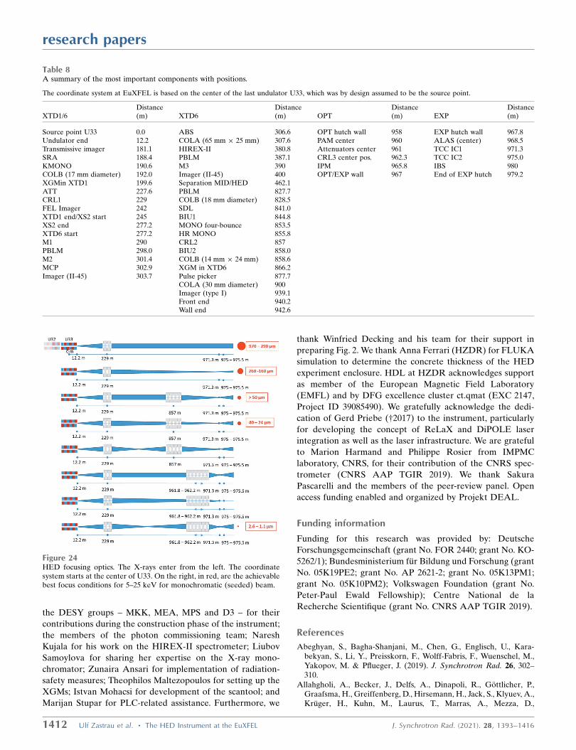
the DESY groups – MKK, MEA, MPS and D3 – for their
contributions during the construction phase of the instrument;
the members of the photon commissioning team; Naresh
Kujala for his work on the HIREX-II spectrometer; Liubov
Samoylova for sharing her expertise on the X-ray mono-
chromator; Zunaira Ansari for implementation of radiation-
safety measures; Theophilos Maltezopoulos for setting up the
XGMs; Istvan Mohacsi for development of the scantool; and
Marijan Stupar for PLC-related assistance. Furthermore, we
thank Winfried Decking and his team for their support in
preparing Fig. 2. We thank Anna Ferrari (HZDR) for FLUKA
simulation to determine the concrete thickness of the HED
experiment enclosure. HDL at HZDR acknowledges support
as member of the European Magnetic Field Laboratory
(EMFL) and by DFG excellence cluster ct.qmat (EXC 2147,
Project ID 39085490). We gratefully acknowledge the dedi-
cation of Gerd Priebe (†2017) to the instrument, particularly
for developing the concept of ReLaX and DiPOLE laser
integration as well as the laser infrastructure. We are grateful
to Marion Harmand and Philippe Rosier from IMPMC
laboratory, CNRS, for their contribution of the CNRS spec-
trometer (CNRS AAP TGIR 2019). We thank Sakura
Pascarelli and the members of the peer-review panel. Open
access funding enabled and organized by Projekt DEAL.
Funding information
Funding for this research was provided by: Deutsche
Forschungsgemeinschaft (grant No. FOR 2440; grant No. KO-
5262/1); Bundesministerium fur Bildung und Forschung (grant
No. 05K19PE2; grant No. AP 2621-2; grant No. 05K13PM1;
grant No. 05K10PM2); Volkswagen Foundation (grant No.
Peter-Paul Ewald Fellowship); Centre National de la
Recherche Scientifique (grant No. CNRS AAP TGIR 2019).
References
Abeghyan, S., Bagha-Shanjani, M., Chen, G., Englisch, U., Kara-bekyan, S., Li, Y., Preisskorn, F., Wolff-Fabris, F., Wuenschel, M.,Yakopov, M. & Pflueger, J. (2019). J. Synchrotron Rad. 26, 302–310.
Allahgholi, A., Becker, J., Delfs, A., Dinapoli, R., Gottlicher, P.,Graafsma, H., Greiffenberg, D., Hirsemann, H., Jack, S., Klyuev, A.,Kruger, H., Kuhn, M., Laurus, T., Marras, A., Mezza, D.,
research papers
1412 Ulf Zastrau et al. � The HED Instrument at the EuXFEL J. Synchrotron Rad. (2021). 28, 1393–1416
Table 8A summary of the most important components with positions.
The coordinate system at EuXFEL is based on the center of the last undulator U33, which was by design assumed to be the source point.
XTD1/6Distance(m) XTD6
Distance(m) OPT
Distance(m) EXP
Distance(m)
Source point U33 0.0 ABS 306.6 OPT hutch wall 958 EXP hutch wall 967.8Undulator end 12.2 COLA (65 mm 25 mm) 307.6 PAM center 960 ALAS (center) 968.5Transmissive imager 181.1 HIREX-II 380.8 Attenuators center 961 TCC IC1 971.3SRA 188.4 PBLM 387.1 CRL3 center pos. 962.3 TCC IC2 975.0KMONO 190.6 M3 390 IPM 965.8 IBS 980COLB (17 mm diameter) 192.0 Imager (II-45) 400 OPT/EXP wall 967 End of EXP hutch 979.2XGMin XTD1 199.6 Separation MID/HED 462.1ATT 227.6 PBLM 827.7CRL1 229 COLB (18 mm diameter) 828.5FEL Imager 242 SDL 841.0XTD1 end/XS2 start 245 BIU1 844.8XS2 end 277.2 MONO four-bounce 853.5XTD6 start 277.2 HR MONO 855.8M1 290 CRL2 857PBLM 298.0 BIU2 858.0M2 301.4 COLB (14 mm 24 mm) 858.6MCP 302.9 XGM in XTD6 866.2Imager (II-45) 303.7 Pulse picker 877.7
COLA (30 mm diameter) 900Imager (type I) 939.1Front end 940.2Wall end 942.6
Figure 24HED focusing optics. The X-rays enter from the left. The coordinatesystem starts at the center of U33. On the right, in red, are the achievablebest focus conditions for 5–25 keV for monochromatic (seeded) beam.

Mozzanica, A., Poehlsen, J., Shefer Shalev, O., Sheviakov, I.,Schmitt, B., Schwandt, J., Shi, X., Smoljanin, S., Trunk, U., Zhang, J.& Zimmer, M. (2019). Nucl. Instrum. Methods Phys. Res. A, 942,162324.
Appel, K., Nakatsutsumi, M., Pelka, A., Priebe, G., Thorpe, I. &Tschentscher, T. (2014). Plasma Phys. Control. Fusion, 57, 014003.
Appleby, G. A. S., Pascarelli, D., Pahl, T., Tschentscher (2017).Synchrotron Radiat. News, 30(5), 6–8.
Barker, L. M. & Hollenbach, R. E. (1965). Rev. Sci. Instrum. 36, 1617–1620.
Basov, D. N. & Chubukov, A. V. (2011). Nat. Phys. 7, 272–276.Battistoni, G., Boehlen, T., Cerutti, F., Chin, P. W., Esposito, L. S.,
Fasso, A., Ferrari, A., Lechner, A., Empl, A., Mairani, A.,
Mereghetti, A., Ortega, P. G., Ranft, J., Roesler, S., Sala, P. R.,Vlachoudis, V. & Smirnov, G. (2015). Ann. Nucl. Energy, 82, 10–18.
Bernhardt, H., Schmitt, A. T., Grabiger, B., Marx-Glowna, B.,Loetzsch, R., Wille, H., Bessas, D., Chumakov, A. I., Ruffer, R.,Rohlsberger, R., Stohlker, T., Uschmann, I., Paulus, G. G. &Schulze, K. S. (2020). Phys. Rev. Res. 2, 023365.
Bionta, M. R., Lemke, H. T., Cryan, J. P., Glownia, J. M., Bostedt, C.,Cammarata, M., Castagna, J. C., Ding, Y., Fritz, D. M., Fry, A. R.,Krzywinski, J., Messerschmidt, M., Schorb, S., Swiggers, M. L. &Coffee, R. N. (2011). Opt. Express, 19, 21855–21865.
Blaj, G., Bhogadi, D., Chang, C., Doering, D., Kenney, C., Kroll, T.,Segal, J., Sokaras, D. & Haller, G. (2019). AIP Conf. Proc. 2054,060037.
research papers
J. Synchrotron Rad. (2021). 28, 1393–1416 Ulf Zastrau et al. � The HED Instrument at the EuXFEL 1413
Table 9Configurations of individual lenses (number and radii of curvature) in all installed CRL systems.
CRL 1, 2 and 3 consist of a so-called transfocator with ten rods which can be individually inserted. The term number refers to the amount of individual Be lenses ineach rod. The apertures of these parabolic lenses relate to the maximum non-clipping illumination. The shown lens configuration in CRL3 can focus all photonenergies from 5 keV up to 20.5 keV without any gap. If tight focusing of higher photon energies is required, either prefocusing with CRL1,2 needs to be used, orweaker lenses have to be replaced with stronger ones. However, the latter will result in gaps for focusing lower photon energies.
Rod 1 2 3 4 5 6 7 8 9 10
CRL1 lens radius (mm) number – 5.8 1 5.0 1 4.0 1 3.5 1 5.8 2 4.0 3 4.0 7 2.0 7 –CRL1 apertures (mm) 4 3.8 3.53 3.16 2.96 3.8 3.16 3.16 2.76 4CRL2 lens radius (mm) number 5.8 1 5.0 1 4.0 1 3.5 1 5.8 2 5.8 4 5.8 7 4.0 10 3.5 10 2.0 8CRL2 apertures (mm) 3.8 3.53 3.16 2.96 3.8 3.8 3.8 3.16 2.96 2.76CRL3 lens radius (mm) number 5.8 1 5.8 3 5.8 4 4.0 10 2.0 10 1.0 10 1.0 10 0.5 10 0.5 10 5.8 2CRL3 apertures (mm) 3.8 3.8 3.8 3.16 2.76 1.95 1.95 1.38 1.38 3.8CRL4 lens radius (mm) number 0.05 up to 50CRL4 apertures (mm) 0.3
Table 10Summary of each 2D imager, 10 Hz operation.
Invasive means that this imager is opaque to the X-ray beam, as opposed to an imager which is transmissive.
2D imagerLocation fromthe source (m) Type Screens and thicknesses
Field of view(mm mm)
Resolution(mm)
IMG-TR 190 Transmissive YAG:Ce 25 mm, diamond 50 mm 25.6 19.2 35IMGFEL 242 Invasive YAG:Ce 100 mm, BN 60 mm, CVD 40 mm 17.62 23.5 15, 15, 59POPInII45-1 303 Transmissive YAG:Ce 100 mm 150 22.7 103POPInII45-2 400 Transmissive YAG:Ce 100 mm 148.4 22.1 112SDLBM-1 845 Transmissive YAG:Ce 1 mm 63 mm 200SDLBM-2 858 Transmissive YAG:Ce 1 mm 63 mm 200HED-IMGPI 940 Transmissive YAG:Ce 50 mm, CVD 40 mm 22.4 39.8 39.32HED-BIU 960 Transmissive YAG:Ce 25, 50, 100 mm N/AHED-PAM 961 Transmissive YAG:Ce 20, 100 mm �5 6 < 10HED-SBM 965 Transmissive YAG:Ce 25 mm & 50 mm for beam split by BIU grating N/AHED-Questar1 971.3 Transmissive Variable 13 8 20HED-Questar2 971.3 Transmissive Variable 13 8 20HED-IBS 978.5 Invasive CVD 500 mm N/A
Table 11Summary of each spectral analyser.
Analyser name Location X-ray range Crystal and bending radius Resolution /spectral range (average) Detector
HIREX-II XTD6 5–25 keV C(110), R = 100 mm �0.2 eV/300 eV PhotonicScienceSi(110), R = 50 and 100 mm GOTTHARD ISi(111), R = 75 mm
HED-flex HED-EXP 5–20 keV C(110), R = 100 m m 0.13 eV/100–200 eV Zyla 4.2 PlusC(111), R = 75 mm Zyla 5.5Si(110), R = 50–150 mm GOTTHARD IISi(111), R = 50–150 mm
CNRS-spec HED-EXP 5–24 keV C(110), R = 100 m m �0.3 eV/100–200 eV Zyla 4.2 PlusC(111), R = 100 mm Zyla 5.5Si(110), R = 50–150 mm PI-MTE:2048BSi(111), R = 75 mm GOTTHARD II

Blaj, G., Caragiulo, P., Dragone, A., Haller, G., Hasi, J., Kenney, C. J.,Kwiatkowski, M., Markovic, B., Segal, J. & Tomada, A. (2016).Proc. SPIE, 9968, 59–68.
Boesenberg, U., Samoylova, L., Roth, T., Zhu, D., Terentyev, S.,Vannoni, M., Feng, Y., van Driel, T. B., Song, S., Blank, V., Sinn, H.,Robert, A. & Madsen, A. (2017). Opt. Express, 25, 2852–2862.
Brygoo, S., Millot, M., Loubeyre, P., Lazicki, A. E., Hamel, S., Qi, T.,Celliers, P. M., Coppari, F., Eggert, J. H., Fratanduono, D. E., Hicks,D. G., Rygg, J. R., Smith, R. F., Swift, D. C., Collins, G. W. & Jeanloz,R. (2015). J. Appl. Phys. 118, 195901.
Cerantola, V., McCammon, C., Kupenko, I., Kantor, I., Marini, C.,Wilke, M., Ismailova, L., Solopova, N., Chumakov, A., Pascarelli, S.& Dubrovinsky, L. (2015). Am. Mineral. 100, 2670–2681.
Cerantola, V., Rosa, A. D., Konopkova, Z., Torchio, R., Brambrink,E., Rack, A., Zastrau, U. & Pascarelli, S. (2021). J. Phys. Condens.Matter, 33, 274003.
Decking, W. et al. (2020). Nat. Photon. 14, 391–397.Descamps, A., Ofori-Okai, K., Appel, V., Cerantola, A., Comley, J.,
Eggert, L., Fletcher, D., Gericke, S., Gode, S., Humphries, O.,Karnbach, A., Lazicki, R., Loetzsch, D., McGonegle, C., Palmer, C.,Plueckthun, T., Preston, R., Redmer, D., Senesky, C., Strohm, I.,Uschmann, T., White, L., Wollenweber, G., Monaco, J., Wark, J.,Hastings, U., Zastrau, G., Gregori, S., Glenzer, S. H. & McBride,E. E. (2020). Sci. Rep. 10, 14564.
De Vido, M., Ertel, K., Wojtusiak, A., O’Donoghue, N., Tomlinson, S.,Divoky, M., Sawicka-Chyla, M., Pilar, J., Mason, P., Phillips, J.,Smith, J. M., Banerjee, S., Butcher, T., Edwards, C., Lucianetti, A.,Mocek, T. & Collier, J. (2019). Advanced Solid State Lasers,p. JTu3A.14. Optical Society of America.
Dong, X., Shu, D. & Sinn, H. (2016). AIP Conf. Proc. 1741, 040027.Drake, R. P. (2010). Phys. Today, 63, 28–33.Schneidmiller, E. A. & Yurkov, M. V. (2011). Photon beam properties
at the European XFEL (December (2010). revision). TechnicalReport. Deutsches Elektronen-Synchrotron (DESY), HamburgGermany.
Fiuza, F., Swadling, G. F., Grassi, A., Rinderknecht, H. G., Higginson,D. P., Ryutov, D. D., Bruulsema, C., Drake, R. P., Funk, S., Glenzer,S., Gregori, G., Li, C. K., Pollock, B. B., Remington, B. A., Ross,J. S., Rozmus, W., Sakawa, Y., Spitkovsky, A., Wilks, S. & Park, H.(2020). Nat. Phys. 16, 916–920.
Geindre, J. P., Mysyrowicz, A., Santos, A. D., Audebert, P., Rousse, A.,Hamoniaux, G., Antonetti, A., Fallies, F. & Gauthier, J. C. (1994).Opt. Lett. 19, 1997.
Geloni, G., Anton, J., Blank, V., Decking, W., Dong, X., Karabekyan,S., Kearney, S., Kocharyan, V., La Civita, D., Liu, S., et al. (2019).Proceedings of the 39th International Free-Electron Laser Confer-ence (FEL2019), 26–30 August 2019, Hamburg, Germany, pp. 242–245. MOP008.
Geloni, G., Kocharyan, V. & Saldin, E. (2011). J. Mod. Opt. 58, 1391–1403.
Gerber, S., Jang, H., Nojiri, H., Matsuzawa, S., Yasumura, H., Bonn,D. A., Liang, R., Hardy, W. N., Islam, Z., Mehta, A., Song, S.,Sikorski, M., Stefanescu, D., Feng, Y., Kivelson, S. A., Devereaux,T. P., Shen, Z. -X., Kao, C. -C., Lee, W. -S., Zhu, D. & Lee, J. S.(2015). Science, 350, 949–952.
Gessler, P., Ali, H., Babies, F., Ballak, K. E., Bamaga, H., Baranasic,B., Bieler, O., Coppola, N., Dornack, K., Eilers, J., et al. (2019).Proceedings of the 17th Biennial International Conference onAccelerator and Large Experimental Physics Control Systems(ICALEPCS2019), 5–11 October 2019, New York, NY, USA, pp.1154–1560. THAPP05.
Gode, S., Rodel, K., Zeil, R., Mishra, M., Gauthier, M., Brack, T.,Kluge, T., MacDonald, M. J., Metzkes, L., Obst, L., Rehwald, M.,Ruyer, C., Schlenvoigt, H. P., Schumaker, W., Sommer, P., Cowan,T. E., Schramm, U., Glenzer, S. & Fiuza, F. (2017). Phys. Rev. Lett.118, 194801.
Grabiger, B., Marx-Glowna, B., Uschmann, I., Loetzsch, R., Paulus,G. G. & Schulze, K. S. (2020). Appl. Phys. Lett. 117, 201102.
Grissonnanche, G., Laliberte, S., Dufour-Beausejour, M., Matusiak,S., Badoux, S., Tafti, F. F., Michon, A., Riopel, O., Cyr-Choiniere, O.,Baglo, J. C., Ramshaw, B. J., Liang, R., Bonn, D. A., Hardy, W. N.,Kramer, S., LeBoeuf, D., Graf, D., Doiron-Leyraud, N. & Taillefer,L. (2016). Phys. Rev. B, 93, 064513.
Grunert, J., Carbonell, M. P., Dietrich, F., Falk, T., Freund, W., Koch,A., Kujala, N., Laksman, J., Liu, J., Maltezopoulos, T., Tiedtke, K.,Jastrow, U. F., Sorokin, A., Syresin, E., Grebentsov, A. & Brovko,O. (2019). J. Synchrotron Rad. 26, 1422–1431.
Hagemann, J., Vassholz, M., Hoeppe, H., Osterhoff, M., Rossello,J. M., Mettin, R., Seiboth, F., Schropp, A., Moller, J., Hallmann, J.,Kim, C., Scholz, M., Boesenberg, U., Schaffer, R., Zozulya, A., Lu,W., Shayduk, R., Madsen, A., Schroer, C. G. & Salditt, T. (2021). J.Synchrotron Rad. 28, 52–63.
Hamos, L. von (1934). Annal. Phys. 411, 252–260.
Harmand, M., Coffee, R., Bionta, M. R., Chollet, M., French, D., Zhu,D., Fritz, D. M., Lemke, H. T., Medvedev, N., Ziaja, B., Toleikis, S. &Cammarata, M. (2013). Nat. Photon. 7, 215–218.
Hauf, S., Heisen, B., Aplin, S., Beg, M., Bergemann, M., Bondar, V.,Boukhelef, D., Danilevsky, C., Ehsan, W., Essenov, S., Fabbri, R.,Flucke, G., Fulla Marsa, D., Gories, D., Giovanetti, G., Hickin, D.,Jarosiewicz, T., Kamil, E., Khakhulin, D., Klimovskaia, A., Kluyver,T., Kirienko, Y., Kuhn, M., Maia, L., Mamchyk, D., Mariani, V.,Mekinda, L., Michelat, T., Munnich, A., Padee, A., Parenti, A.,Santos, H., Silenzi, A., Teichmann, M., Weger, K., Wiggins, J.,Wrona, K., Xu, C., Youngman, C., Zhu, J., Fangohr, H. &Brockhauser, S. (2019). J. Synchrotron Rad. 26, 1448–1461.
Heisen, B., Boukhelef, D., Esenov, S., Hauf, S., Kozlova, I., Maia, L.,Parenti, A., Szuba, J., Weger, K., Wrona, K. & Youngman, C.(2013). Proceedings of the 14th International Conference onAccelerator and Large Experimental Physics Control Systems(ICALEPCS2013), 6–11 October 2013, San Francisco, CA, USA,pp. 1465–1468. FRCOAAB02.
Holy, V., Kubena, I., Ohlidal, I., Lischka, W. & Plotz, W. (1993). Phys.Rev. B, 47, 15896–15903.
Hwang, H., Kim, T., Cynn, H., Vogt, T., Husband, R. J., Appel, K.,Baehtz, C., Ball, O. B., Baron, M. A., Briggs, R., Bykov, M., Bykova,E., Cerantola, V., Chantel, J., Coleman, A. L., Dattlebaum, D.,Dresselhaus-Marais, L. E., Eggert, J. H., Ehm, L., Evans, W. J.,Fiquet, G., Frost, M., Glazyrin, K., Goncharov, A. F., Jenei, Z., Kim,J., Konopkova, Z., Mainberger, J., Makita, M., Marquardt, H.,McBride, E. E., McHardy, J. D., Merkel, S., Morard, G., O’Bannon,E. F. III, Otzen, C., Pace, E. J., Pelka, A., Pepin, C. M., Pigott, J. S.,Prakapenka, V. B., Prescher, C., Redmer, R., Speziale, S.,Spiekermann, G., Strohm, C., Sturtevant, B. T., Velisavljevic, N.,Wilke, M., Yoo, C., Zastrau, U., Liermann, H., McMahon, M. I.,McWilliams, R. S. & Lee, Y. (2021). J. Phys. Chem. Lett. 12, 3246–3252.
Jenei, Z., Liermann, H. P., Husband, R., Mendez, A. S. J., Pennicard,D., Marquardt, H., O’Bannon, E. F., Pakhomova, A., Konopkova,Z., Glazyrin, K., Wendt, M., Wenz, S., McBride, E. E., Morgenroth,W., Winkler, B., Rothkirch, A., Hanfland, M. & Evans, W. J. (2019).Rev. Sci. Instrum. 90, 065114.
Karbstein, F. & Mosman, E. A. (2019). Phys. Rev. D, 100, 033002.
Karcher, V., Roling, S., Samoylova, L., Buzmakov, A., Zastrau, U.,Appel, K., Yurkov, M., Schneidmiller, E., Siewert, F. & Zacharias,H. (2021). J. Synchrotron Rad. 28, 350–361.
Kim, J. B., Gode, S. & Glenzer, S. H. (2016). Rev. Sci. Instrum. 87,11E328.
Kirkwood, H. J., Letrun, R., Tanikawa, T., Liu, J., Nakatsutsumi, M.,Emons, M., Jezynski, T., Palmer, G., Lederer, M., Bean, R., Buck, J.,Di Dio Cafisio, S., Graceffa, R., Grunert, J., Gode, S., Hoppner, H.,Kim, Y., Konopkova, Z., Mills, G., Makita, M., Pelka, A., Preston,T. R., Sikorski, M., Takem, C. M. S., Giewekemeyer, K., Chollet, M.,Vagovic, P., Chapman, H. N., Mancuso, A. P. & Sato, T. (2019). Opt.Lett. 44, 1650–1653.
research papers
1414 Ulf Zastrau et al. � The HED Instrument at the EuXFEL J. Synchrotron Rad. (2021). 28, 1393–1416

Klackova, I., Blaj, G., Denes, P., Dragone, A., Gode, S., Hauf, S.,Januschek, F., Joseph, J. & Kuster, M. (2019). J. Instrum. 14,C01008.
Klementiev, K. & Chernikov, R. (2020). kklmn/xrt: Release 1.3.4,https://doi.org/10.5281/zenodo.3838709.
Kluge, T., Bussmann, M., Chung, H., Gutt, C., Huang, L. G.,Zacharias, M., Schramm, U. & Cowan, T. E. (2016). Phys. Plasmas,23, 033103.
Kluge, T., Gutt, C., Huang, L. G., Metzkes, J., Schramm, U.,Bussmann, M. & Cowan, T. E. (2014). Phys. Plasmas, 21, 033110.
Koch, A., Risch, J., Freund, W., Maltezopoulos, T., Planas, M. &Grunert, J. (2019). J. Synchrotron Rad. 26, 1489–1495.
Konopkova, Z., McWilliams, R. S., Gomez-Perez, N. & Goncharov,A. F. (2016). Nature, 534, 99–101.
Kujala, N., Freund, W., Liu, J., Koch, A., Falk, T., Planas, M., Dietrich,F., Laksman, J., Maltezopoulos, T., Risch, J., Dall’Antonia, F. &Grunert, J. (2020). Rev. Sci. Instrum. 91, 103101.
Lengeler, B., Schroer, C., Tummler, J., Benner, B., Richwin, M.,Snigirev, A., Snigireva, I. & Drakopoulos, M. (1999). J. SynchrotronRad. 6, 1153–1167.
Liermann, H. P., Konopkova, Z., Appel, K., Prescher, C., Schropp, A.,Cerantola, V., Husband, R. J., McHardy, J. D., McMahon, M. I.,McWilliams, R. S., Pepin, C. M., Mainberger, J., Roeper, M.,Berghauser, A., Damker, H., Talkovski, P., Foese, M., Kujala, N.,Ball, O. B., Baron, M. A., Briggs, R., Bykov, M., Bykova, E.,Chantel, J., Coleman, A. L., Cynn, H., Dattelbaum, D., Dressel-haus-Marais, L. E., Eggert, J. H., Ehm, L., Evans, W. J., Fiquet, G.,Frost, M., Glazyrin, K., Goncharov, A. F., Hwang, H., Jenei, Z.,Kim, J.-Y., Langenhorst, F., Lee, Y., Makita, M., Marquardt, H.,McBride, E. E., Merkel, S., Morard, G., O’Bannon, E. F., Otzen, C.,Pace, E. J., Pelka, A., Pigott, J. S., Prakapenka, V. B., Redmer, R.,Sanchez-Valle, C., Schoelmerich, M., Speziale, S., Spiekermann, G.,Sturtevant, B. T., Toleikis, S., Velisavljevic, N., Wilke, M., Yoo, C.-S.,Baehtz, C., Zastrau, U. & Strohm, C. (2021). J. Synchrotron Rad.28, 688–706.
Lin, J. F., Struzhkin, V. V., Jacobsen, S. D., Hu, M. Y., Chow, P., Kung,J., Liu, H., Mao, H. K. & Hemley, R. J. (2005). Nature, 436, 377–380.
Liu, J. Y., Hu, J., Zhang, Q., Graf, D., Cao, H. B., Radmanesh, S. M. A.,Adams, D. J., Zhu, Y. L., Cheng, G. F., Liu, X., Phelan, W. A., Wei,J., Jaime, M., Balakirev, F., Tennant, D. A., DiTusa, J. F., Chiorescu,I., Spinu, L. & Mao, Z. Q. (2017). Nat. Mater. 16, 905–910.
Liu, S., Decking, W., Kocharyan, V., Saldin, E., Serkez, S., Shayduk,R., Sinn, H. & Geloni, G. (2019). Phys. Rev. Accel. Beams, 22,060704.
Loubeyre, P., Brygoo, J., Eggert, J., Celliers, P. M., Spaulding, D. K.,Rygg, J. R., Boehly, T. R., Collins, G. W. & Jeanloz, R. (2012). Phys.Rev. B, 86, 144115.
Lu, W., Friedrich, B., Noll, T., Zhou, J., Hallmann, G., Ansaldi, T.,Roth, T., Serkez, S., Geloni, G., Madsen, A. & Eisebitt, S. (2018).Rev. Sci. Instrum. 89, 063121.
Madsen, A., Hallmann, J., Ansaldi, G., Roth, T., Lu, W., Kim, C.,Boesenberg, U., Zozulya, A., Moller, J., Shayduk, R., Scholz, M.,Bartmann, A., Schmidt, A., Lobato, I., Sukharnikov, K., Reiser, M.,Kazarian, K. & Petrov, I. (2021). J Synchrotron Rad, 28, 637–649.
Maltezopoulos, T., Dietrich, F., Freund, W., Jastrow, U. F., Koch, A.,Laksman, J., Liu, J., Planas, M., Sorokin, A. A., Tiedtke, K. &Grunert, J. (2019). J. Synchrotron Rad. 26, 1045–1051.
Meza-Galvez, J., Gomez-Perez, N., Marshall, A. S., Coleman, A. L.,Appel, K., Liermann, H. P., McMahon, M. I., Konopkova, Z. &McWilliams, R. S. (2020). J. Appl. Phys. 127, 195902.
Millot, M., Dubrovinskaia, N., ernok, A., Blaha, S., Dubrovinsky, L.,Braun, D. G., Celliers, P. M., Collins, G. W., Eggert, J. H. & Jeanloz,R. (2015). Science, 347, 418–420.
Mitzner, R., Siemer, B., Neeb, M., Noll, T., Siewert, F., Roling, S.,Rutkowski, M., Sorokin, A. A., Richter, M., Juranic, P., Tiedtke, K.,Feldhaus, J., Eberhardt, W. & Zacharias, H. (2008). Opt. Express,16, 19909–19919.
Mozzanica, A., Andra, M., Barten, R., Bergamaschi, A., Chiriotti, S.,Bruckner, M., Dinapoli, R., Frojdh, E., Greiffenberg, D., Leonarski,F., Lopez-Cuenca, C., Mezza, D., Redford, S., Ruder, C., Schmitt,B., Shi, X., Thattil, D., Tinti, G., Vetter, S. & Zhang, J. (2018).Synchrotron Radiat. News, 31(6), 16–20.
Mozzanica, A., Bergamaschi, A., Dinapoli, R., Graafsma, H.,Greiffenberg, D., Henrich, B., Johnson, I., Lohmann, M., Valeria,R., Schmitt, B. & Xintian, S. (2012). J. Instrum. 7, C01019.
Muller-Buschbaum, P. (2003). Anal. Bioanal. Chem. 376, 3–10.Mydosh, J. A. & Oppeneer, P. M. (2011). Rev. Mod. Phys. 83, 1301–
1322.Nakatsutsumi, M., Appel, C., Baehtz, B., Chen, B., Cowan, S., Gode,
Z., Konopkova, A., Pelka, G., Priebe, A., Schmidt, K., Sukharnikov,I., Thorpe, Th., Tschentscher, T. & Zastrau, U. (2016). Plasma Phys.Control. Fusion, 59, 014028.
Nakatsutsumi, M., Appel, K., Priebe, G., Thorpe, I., Pelka, A., Muller,B. & Tschentscher, Th. (2014). Scientific Instrument High EnergyDensity Physics (HED). Conceptual Design Report: European X-ray Free-Electron Laser Facility GmbH, Schenefeld, Germany.
Nakatsutsumi, M. & Tschentscher, Th. (2013). Scientific InstrumentHigh Energy Density Physics (HED). Technical Design Report.European X-ray Free-Electron Laser Facility GmbH, Schenefeld,Germany.
Obst, L., Gode, S., Rehwald, M., Brack, F., Branco, J., Bock, S.,Bussmann, M., Cowan, T. E., Curry, C. B., Fiuza, F., Gauthier, M.,Gebhardt, R., Helbig, U., Huebl, A., Hubner, U., Irman, A., Kazak,L., Kim, J. B., Kluge, T., Kraft, S., Loeser, M., Metzkes, J., Mishra,R., Rodel, C., Schlenvoigt, H., Siebold, M., Tiggesbaumker, J.,Wolter, S., Ziegler, T., Schramm, U., Glenzer, S. H. & Zeil, K.(2017). Sci. Rep. 7, 10248.
Palmer, G., Kellert, M., Wang, J., Emons, M., Wegner, U., Kane, D.,Pallas, F., Jezynski, T., Venkatesan, S., Rompotis, D., Brambrink, E.,Monoszlai, B., Jiang, M., Meier, J., Kruse, K., Pergament, M. &Lederer, M. J. (2019). J. Synchrotron Rad. 26, 328–332.
Phillips, J. P., Banerjee, S., Mason, P., Smith, J., Spear, J., De Vido, M.,Ertel, K., Butcher, T., Quinn, G., Clarke, D., Edwards, C.,Hernandez-Gomez, C. & Collier, J. (2021). Opt. Lett. 46, 1808.
Phillips, P. J., Mason, P., Ertel, K., Smith, J., De-Vido, M., Butcher, T.,Tomlinson, S., Suarez-Merchan, J. E., Lintern, A., Costello, B.,Hollingham, I., Norton, A., Tyldesley, M., Hernandez-Gomez, C.,Edwards, C., Collier, J., Hoppner, H., Toncian, T., Zastrau, U. &Moller, D. (2019). Proc. SPIE, 10898, 108980K.
Pikuz, T., Faenov, A., Matsuoka, T., Matsuyama, S., Yamauchi, K.,Ozaki, N., Albertazzi, B., Inubushi, Y., Yabashi, M., Tono, K., Sato,Y., Yumoto, H., Ohashi, H., Pikuz, S., Grum-Grzhimailo, A. N.,Nishikino, M., Kawachi, T., Ishikawa, T. & Kodama, R. (2015). Sci.Rep. 5, 17713.
Prencipe, I., Fuchs, J., Pascarelli, S., Schumacher, D. W., Stephens,R. B., Alexander, N. B., Briggs, R., Buscher, M., Cernaianu, M. O.,Choukourov, A., De Marco, M., Erbe, A., Fassbender, J., Fiquet, G.,Fitzsimmons, P., Gheorghiu, C., Hund, J., Huang, L. G., Harmand,M., Hartley, N. J., Irman, A., Kluge, T., Konopkova, Z., Kraft, S.,Kraus, D., Leca, V., Margarone, D., Metzkes, J., Nagai, K., Nazarov,W., Lutoslawski, P., Papp, D., Passoni, M., Pelka, A., Perin, J. P.,Schulz, J., Smid, M., Spindloe, C., Steinke, S., Torchio, R., Vass, C.,Wiste, T., Zaffino, R., Zeil, K., Tschentscher, T., Schramm, U. &Cowan, T. E. (2017). High Pow Laser Sci Eng, 5, e17.
Preston, T. R., Gode, S., Schwinkendorf, J., Appel, K., Brambrink, E.,Cerantola, V., Hoppner, H., Makita, M., Pelka, A., Prescher, C.,Sukharnikov, K., Schmidt, A., Thorpe, I., Toncian, T., Amouretti,A., Chekrygina, D., Falcone, R. W., Falk, K., Fletcher, L. B., Galtier,E., Harmand, M., Hartley, N. J., Hau-Riege, S. P., Heimann, P.,Huang, L. G., Humphries, O. S., Karnbach, O., Kraus, D., Lee, H. J.,Nagler, B., Ren, S., Schuster, A. K., Smid, M., Voigt, K., Zhang, M.& Zastrau, U. (2020). J. Instrum. 15, P11033.
Randolph, L., Banjafar, M., Preston, T. R., Yabuuchi, T., Makita, M.,Dover, N. P., Rodel, C., Gode, S., Inubushi, Y., Jakob, G., Kaa, J.,.Kon, A., Koga, J. K., Ksenzov, D., Matsuoka, T., Nishiuchi, M.,
research papers
J. Synchrotron Rad. (2021). 28, 1393–1416 Ulf Zastrau et al. � The HED Instrument at the EuXFEL 1415

Paulus, M., Schon, F., Sueda, K., Sentoku, Y., Togashi, T., Vafaee-Khanjani, M., Bussmann, M., Cowan, T. E., Klaui, M., Fortmann-Grote, C., Mancuso, A. P., Kluge, T., Gutt, C. & Nakatsutsumi, M.(2020). arXiv: 2012.15076 [physics. plasm-ph].
Redford, S., Andra, M., Barten, R., Bergamaschi, A., Bruckner, M.,Chiriotti, S., Dinapoli, R., Frojdh, E., Greiffenberg, D., Kim, K. S.,Lee, J. H., Lopez-Cuenca, C., Meyer, M., Mezza, D., Mozzanica, A.,Park, S., Ruder, C., Schmitt, B., Shi, X., Thattil, D., Tinti, G., Vetter,S. & Zhang, J. (2020). J. Instrum. 15, C02025.
Redford, S., Andra, M., Barten, R., Bergamaschi, A., Bruckner, M.,Dinapoli, R., Frojdh, E., Greiffenberg, D., Lopez-Cuenca, C.,Mezza, D., Mozzanica, A., Ramilli, M., Ruat, M., Ruder, C.,Schmitt, B., Shi, X., Thattil, D., Tinti, G., Vetter, S. & Zhang, J.(2018). J. Instrum. 13, C01027.
Riedel, R., Al-Shemmary, A., Gensch, M., Golz, T., Harmand, M.,Medvedev, N., Prandolini, M. J., Sokolowski-Tinten, K., Toleikis, S.,Wegner, U., Ziaja, B., Stojanovic, N. & Tavella, F. (2013). Nat.Commun. 4, 1731.
Roling, S., Appel, K., Braun, S., Buzmakov, A., Chubar, O., Gawlitza,P., Samoylova, L., Siemer, B., Schneidmiller, E., Sinn, H., Siewert,F., Tschentscher, T., Wahlert, F., Wostmann, M., Yurkov, M. &Zacharias, H. (2017). Proc. SPIE, 9210, 92100B.
Roth, S. V. (2016). J. Phys. Condens. Matter, 28, 403003.Ruyer, C., Bolanos, S., Albertazzi, B., Chen, S. N., Antici, P., Boker, J.,
Dervieux, V., Lancia, L., Nakatsutsumi, M., Romagnani, L.,Shepherd, R., Swantusch, M., Borghesi, M., Willi, O., Pepin, H.,Starodubtsev, M., Grech, M., Riconda, C., Gremillet, L. & Fuchs, J.(2020). Nat. Phys. 16, 983–988.
Samoylova, L., Boesenberg, U., Chumakov, A., Kaganer, V., Petrov,I., Roth, T., Ruffer, R., Sinn, H., Terentyev, S. & Madsen, A. (2019).J. Synchrotron Rad. 26, 1069–1072.
Schlenvoigt, H., Heinzl, T., Schramm, U., Cowan, T. E. & Sauerbrey,R. (2016). Phys. Scr. 91, 023010.
Schmidt, A. & Dommach, M. (2015). HV Guidelines for ScientificInstruments. Technical Report. European X-ray Free-ElectronLaser Facility GmbH, Schenefeld, Germany.
Scholz, M. & Zhao, Z. T. (2019). Proceedings of the 39th InternationalFree-Electron Laser Conference (FEL2019), 26–30 August 2019,Hamburg, Germany. MOA04.
Schropp, A., Hoppe, R., Meier, V., Patommel, J., Seiboth, F., Lee,H. J., Nagler, B., Galtier, E. C., Arnold, B., Zastrau, U., Hastings,J. B., Nilsson, D., Uhlen, F., Vogt, U., Hertz, H. M. & Schroer, C. G.(2013). Sci. Rep. 3, 1633.
Schropp, A., Hoppe, R., Meier, V., Patommel, J., Seiboth, F., Ping, Y.,Hicks, D. G., Beckwith, M. A., Collins, G. W., Higginbotham, A.,Wark, J. S., Lee, H. J., Nagler, B., Galtier, E. C., Arnold, B., Zastrau,U., Hastings, J. B. & Schroer, C. G. (2015). Sci. Rep. 5, 11089.
Schropp, A., Patommel, J., Seiboth, F., Arnold, B., Galtier, E. C., Lee,H. J., Nagler, B., Hastings, J. B. & Schroer, C. G. (2012). Proc. SPIE,8504, 73–79.
Sinn, H., Dommach, M., Dickert, B., Di Felice, M., Dong, X., Eidam,J., Finze, D., Freijo-Martin, I., Gerasimova, N., Kohlstrunk, N., LaCivita, D., Meyn, F., Music, V., Neumann, M., Petrich, M., Rio, B.,Samoylova, L., Schmidtchen, S., Stormer, M., Trapp, A., Vannoni,M., Villanueva, R. & Yang, F. (2019). J. Synchrotron Rad. 26, 692–699.
Smıd, M., Baehtz, A., Pelka, A., Laso Garcıa, S., Gode, J., Grenzer, T.,Kluge, Z., Konopkova, M., Makita, I., Prencipe, I., Preston, T. R.,Rodel, M. & Cowan, T. E. (2020). Rev. Sci. Instrum. 91, 123501.
Sorokin, A. A., Bican, Y., Bonfigt, S., Brachmanski, M., Braune, M.,Jastrow, U. F., Gottwald, A., Kaser, H., Richter, M. & Tiedtke, K.(2019). J. Synchrotron Rad. 26, 1092–1100.
Sperling, P., Gamboa, E. J., Lee, H. J., Chung, H. K., Galtier, Y.,Omarbakiyeva, Y., Reinholz, H., Ropke, U., Zastrau, J., Hastings, J.,Fletcher, L. B. & Glenzer, S. H. (2015). Phys. Rev. Lett. 115, 115001.
Spiekermann, G., Kupenko, I., Petitgirard, S., Harder, M., Nyrow, A.,Weis, C., Albers, C., Biedermann, N., Libon, L., Sahle, C. J.,Cerantola, V., Glazyrin, K., Konopkova, Z., Sinmyo, R., Morgen-
roth, W., Sergueev, I., Yavas, H., Dubrovinsky, L., Tolan, M.,Sternemann, C. & Wilke, M. (2020). J. Synchrotron Rad. 27, 414–424.
Tschentscher, T., Bressler, C., Grunert, J., Madsen, A., Mancuso, A.,Meyer, M., Scherz, A., Sinn, H. & Zastrau, U. (2017). Appl. Sci. 7,592.
Ueda, K., Oh, T., Yang, B. J., Kaneko, R., Fujioka, J., Nagaosa, N. &Tokura, Y. (2017). Nat. Commun. 8, 15515.
Umemoto, K., Wentzcovitch, R. M. & Allen, P. B. (2006). Science, 311,983–986.
Vannoni, M., Freijo Martın, I., Schmidtchen, S., Baumann, T. M.,Meyer, M. & Music, V. (2019). J. Synchrotron Rad. 26, 1110–1114.
Vinko, S. M., Ciricosta, O., Cho, B. I., Engelhorn, K., Chung, H.,Brown, C. R. D., Burian, J., Chalupsky, J., Falcone, R. W., Graves,C., Hajkova, V., Higginbotham, A., Juha, L., Krzywinski, J., Lee,H. J., Messerschmidt, M., Murphy, C. D., Ping, Y., Scherz, A.,Schlotter, W., Toleikis, S., Turner, J. J., Vysin, L., Wang, T., Wu, B.,Zastrau, U., Zhu, D., Lee, R. W., Heimann, P. A., Nagler, B. &Wark, J. S. (2012). Nature, 482, 59–62.
Wang, T., Toncian, T., Wei, M. S. & Arefiev, A. V. (2019). Phys.Plasmas, 26, 013105.
Weise, H. & Decking, W. (2017). Proceedings of the International FreeElectron Laser Conference (FEL’17), 20–25 August 2017, Santa Fe,NM, USA, pp. 9–13. MOC03.
Wheeler, J. A., Borot, A., Monchoce, S., Vincenti, H., Ricci, A.,Malvache, A., Lopez-Martens, R. & Quere, F. (2012). Nat. Photon.6, 829–833.
Wilks, S. C., Langdon, A. B., Cowan, T. E., Roth, M., Singh, M.,Hatchett, S., Key, M. H., Pennington, D., MacKinnon, A. &Snavely, R. A. (2001). Phys. Plasmas, 8, 542–549.
Wollenweber, L., Preston, T. R., Descamps, A., Cerantola, V., Comley,A., Eggert, J. H., Fletcher, L. B., Geloni, G., Gericke, D. O.,Glenzer, S. H., Gode, S., Hastings, J., Humphries, O. S., Jenei, A.,Karnbach, O., Konopkova, Z., Loetzsch, R., Marx-Glowna, B.,McBride, E. E., McGonegle, D., Monaco, G., Ofori-Okai, B. K.,Palmer, C. A. J., Pluckthun, C., Redmer, R., Strohm, C., Thorpe, I.,Tschentscher, T., Uschmann, I., Wark, J. S., White, T. G., Appel, K.,Gregori, G. & Zastrau, U. (2021). Rev. Sci. Instrum. 92, 013101.
Wosnitza, J., Zvyagin, S. A. & Zherlitsyn, S. (2016). Rep. Prog. Phys.79, 074504.
Wostmann, M., Mitzner, T., Noll, S., Roling, B., Siemer, F., Siewert, S.,Eppenhoff, F., Wahlert, F. & Zacharias, H. (2013). J. Phys. B At.Mol. Opt. Phys. 46, 164005.
Yoneda, H., Inubushi, Y., Nagamine, K., Michine, Y., Ohashi, H.,Yumoto, H., Yamauchi, K., Mimura, H., Kitamura, H., Katayama,T., Ishikawa, T. & Yabashi, M. (2015). Nature, 524, 446–449.
Zastrau, U., Audebert, P., Bernshtam, V., Brambrink, E., Kampfer, T.,Kroupp, E., Loetzsch, R., Maron, Y., Ralchenko, Y., Reinholz, H.,Ropke, G., Sengebusch, A., Stambulchik, E., Uschmann, I.,Weingarten, L. & Forster, E. (2010). Phys. Rev. E, 81, 026406.
Zastrau, U., Brown, C. R. D., Doppner, T., Glenzer, S. H., Gregori, G.,Lee, H. J., Marschner, H., Toleikis, S., Wehrhan, O. & Forster, E.(2012). J. Instrum. 7, P09015.
Zastrau, U., Woldegeorgis, A., Forster, E., Loetzsch, R., Marschner,H. & Uschmann, I. (2013). J. Instrum. 8, P10006.
Zastrau, U., McMahon, M., Appel, K., Baehtz, C., Brambrink, E.,Briggs, R., Butcher, T., Cauble, B., Chen, B. & Damker, H. (2017).Dynamic Laser Compression Experiments at the HED Instrumentof European XFEL. Conceptual Design Report. European X-rayFree-Electron Laser Facility GmbH, Schenefeld, Germany.
Zhu, D., Cammarata, M., Feldkamp, J. M., Fritz, D. M., Hastings, J. B.,Lee, S., Lemke, H. T., Robert, A., Turner, J. L. & Feng, Y. (2012).Appl. Phys. Lett. 101, 034103.
Zozulya, A., Batchelor, L., Appel, K., Boesenberg, U., Hallmann, J.,Kim, C., Lobato, I., Lu, W., Mammen, C., Moller, J., Roth, T.,Samoylova, L., Scholz, M., Shayduk, R., Sukharnikov, K. &Madsen, A. (2019). Proc. SPIE, 11111, 111110H.
research papers
1416 Ulf Zastrau et al. � The HED Instrument at the EuXFEL J. Synchrotron Rad. (2021). 28, 1393–1416