the geometric design of spherical mechanical …
TRANSCRIPT

THE GEOMETRIC DESIGN OF SPHERICAL MECHANICAL LINKAGES
WITH DIFFERENTIAL TASK SPECIFICATIONS: EXPERIMENTAL SET UP
AND APPLICATIONS
A Thesis
by
PHANI NEEHAR KAPILA BALA
Submitted to the Office of Graduate Studies of
Texas A&M University
in partial fulfillment of the requirements for the degree of
MASTER OF SCIENCE
August 2011
Major Subject: Mechanical Engineering

The Geometric Design of Spherical Mechanical Linkages with Differential Task
Specifications: Experimental Set Up and Applications
Copyright 2011 Phani Neehar Kapila Bala

THE GEOMETRIC DESIGN OF SPHERICAL MECHANICAL LINKAGES
WITH DIFFERENTIAL TASK SPECIFICATIONS: EXPERIMENTAL SET UP
AND APPLICATIONS
A Thesis
by
PHANI NEEHAR KAPILA BALA
Submitted to the Office of Graduate Studies of
Texas A&M University
in partial fulfillment of the requirements for the degree of
MASTER OF SCIENCE
Approved by:
Co-Chairs of Committee, Reza Langari
Nina Robson
Committee Member, Sivakumar Rathinam
Head of Department, Dennis O‟Neal
August 2011
Major Subject: Mechanical Engineering

iii
ABSTRACT
The Geometric Design of Spherical Mechanical Linkages with Differential Task
Specifications: Experimental Set Up and Applications.
(August 2011)
Kapila Bala Phani Neehar, B.Tech., Mahatma Gandhi Institute of Technology, India
Co-Chairs of Advisory Committee: Dr. Nina Robson
Dr. Reza Langari
The thesis focuses on the development of an experimental set up for a recently
developed failure recovery technique of spatial robot manipulators. Assuming a general
configuration of the spatial robot arm, a task is specified. This task contains constraints
on position, velocity and acceleration to be satisfied. These constraints are derived from
contact and curvature specifications. The technique synthesizes the serial chain and tests
if the task can be satisfied in case of a joint failure. An experimental set up was
developed in order to validate the failure recovery technique. It includes a robot arm
mounted on a movable platform. The arm and platform are controlled by NI sbRIO
board and are programmed in LabVIEW. The experimental results of the failure
recovery technique for the case of Elbow failure were obtained in Mathematica by fixing
the faulty joint at an angle, these results were later tested on the robot arm and platform
and satisfaction of task was obtained.
The thesis considers two applications of the synthesis of spherical five –degree-
of-freedom serial chains: Power assist for human therapeutic movement and Synthesis of

iv
Parallel Mechanical Linkages. Spherical TS chains have been synthesized for these two
applications using the Mathematica software and the mechanisms were able to satisfy
the task constraints.

v
DEDICATION
To my parents, mentors and friends

vi
ACKNOWLEDGEMENTS
First and foremost I would like to acknowledge God for giving me this
opportunity and my family members for letting me study the masters degree in the
United States. I thank my advisor, Dr. Robson, for guiding me throughout the research
and graduate studies. She helped me in many ways to develop myself professionally and
academically and by being patient with me in both success and failure of acquiring
results.
I would like to thank my committee chair, Dr. Langari and my committee
member Dr. Rathinam, for their guidance and support throughout the course of this
research.
Thanks also go to my friends and colleagues and the department faculty and
staff for making my time at Texas A&M University a great experience. I also want to
extend my gratitude to National Instruments Inc., who provided controller for the
project, and to all the Texas teachers and students who were willing to participate in my
research.
Finally, thanks to my mother and father for their encouragement and love.

vii
TABLE OF CONTENTS
Page
ABSTRACT .............................................................................................................. iii
DEDICATION .......................................................................................................... v
ACKNOWLEDGEMENTS ...................................................................................... vi
TABLE OF CONTENTS .......................................................................................... vii
LIST OF FIGURES ................................................................................................... ix
LIST OF TABLES .................................................................................................... xi
1. INTRODUCTION ............................................................................................... 1
1.1 Overview .............................................................................................. 1
2. LITERATURE SURVEY ................................................................................... 2
2.1 Geometric Design of Serial Chains with Velocity and Acceleration
Specifications ....................................................................................... 2
2.1.1 Task Specification .................................................................. 4
2.1.2 Topology Selection ................................................................ 4
2.1.3 Dimensional Synthesis ........................................................... 6
2.1.4 Trajectory Planning ................................................................ 7
2.2 Summary of the Literature Survey ....................................................... 7
3. CONTRIBUTIONS ............................................................................................. 10
4. GEOMETRIC DESIGN OF A TS MECHANICAL LINKAGE WITH
DIFFERENTIAL TASK SPECIFICATIONS .................................................... 11
4.1 Stages of Geometric Design for the TS Chain ..................................... 12
4.1.1 Task Specification .................................................................. 12
4.1.2 Synthesis of TS Chain ............................................................ 14
4.1.3 Kinematic Specification ......................................................... 15
4.2 Design Procedure ................................................................................. 17
4.3 Trajectory Planning .............................................................................. 20

viii
5. EXPERIMENTAL VALIDATION OF THE EXISTING FAILURE
RECOVERY SYNTHESIS TECHNIQUE ......................................................... 24
5.1 Failure Recovery Synthesis Technique ................................................... 24
5.2 Problem under Consideration: Elbow Joint Failure ................................ 25
5.2.1 The Movable Platform ................................................................ 27
5.2.2 The Robot Arm ............................................................................ 29
5.2.3 Integration of the Robot Arm and Platform System ................... 30
5.3 Components in the Casing ....................................................................... 31
5.4 Control System ........................................................................................ 32
5.4.1 Programming the Robot Arm ...................................................... 35
5.4.2 Software Programming and Execution........................................ 35
5.5 Power System .......................................................................................... 43
5.6 Communication System .......................................................................... 43
5.7 Testing the Failure Recovery Technique ................................................ 44
5.8 Summary of the Test ............................................................................... 50
5.9 Comments ................................................................................................ 51
6. DESIGN OF SPHERICAL MECHANICAL LINKAGES FOR REAL
WORLD APPLICATIONS ................................................................................. 53
6.1 Power Assist Mechanism ........................................................................ 53
6.2 Synthesis of Parallel Mechanical Linkages ............................................. 57
7. CONCLUSIONS AND FUTURE DIRECTIONS ............................................. 60
REFERENCES .......................................................................................................... 62
APPENDIX A. ELECTRONIC SPEED CONTROLLERS ..................................... 65
APPENDIX B. NI sbRIO 9632XT – REAL TIME CONTROLLER ....................... 67
VITA.. .……………………………………………………………………………… 69
Page

ix
LIST OF FIGURES
Page
Figure 1. „T‟ and the „S‟ joints ........................................................................................ 11
Figure 2. „TS‟ serial chain ............................................................................................... 12
Figure 3. Task specifications of a moving frame M with respect to a fixed frame F ..... 13
Figure 4. A planar body ................................................................................................... 15
Figure 5. Description of a moving frame M and a fixed frame F ................................... 17
Figure 6. Trajectory with two via points ......................................................................... 20
Figure 7. TS chain synthesized in Mathematica ............................................................. 23
Figure 8. The robot arm mounted in front of the Mars Rover ........................................ 24
Figure 9. The „TRT‟ serial chain ..................................................................................... 26
Figure 10. The „R‟ revolute joint and the „T‟ joint or the universal joint ........................ 26
Figure 11. The SMP platform .......................................................................................... 28
Figure 12. The robot arm .................................................................................................. 29
Figure 13. Integration of the Lynxmotion AL5D robot arm on the SMP platform ......... 30
Figure 14. Casing of the SMP platform ........................................................................... 31
Figure 15. Architecture for the control of arm and platform............................................ 32
Figure 16. Block diagram interface of LabVIEW VI for top level implementation ....... 38
Figure 17. The front panel interface in LabVIEW for top level implementation ............ 39
Figure 18. Block diagram in LabVIEW for middle level implementation ...................... 40
Figure 19. Front panel interface in LabVIEW for robot arm ........................................... 42

x
Figure 20. Robot arm with infrared markers fixed at different joints .............................. 45
Figure 21. Set up of infrared detection cameras in VICON motion capture system ........ 46
Figure 22. Elbow failure in a T-R-T chain ....................................................................... 47
Figure 23. Healthy T-R-T serial chain ............................................................................. 49
Figure 24. Crippled configuration TT of the TRT ........................................................... 50
Figure 25. Power Assist for human therapeutic movement ............................................. 53
Figure 26. The arm of the worker and mechanism following a specified trajectory ....... 55
Figure 27. Synthesis result of Parallel Mechanical Linkages .......................................... 58
Figure 28. Electronic Speed Controllers .......................................................................... 65
Figure 29. Ni sbRIO 9632XT ........................................................................................... 67
Page

xi
LIST OF TABLES
Page
Table 1. The initial and final positions, velocities and accelerations ............................... 21
Table 2. The task specification for the synthesis of TS chain .......................................... 22
Table 3. Solution to the synthesis of TS chain ................................................................. 23
Table 4. Task specification for the rover and arm to satisfy ............................................ 44
Table 5. Joint limits of the T-R-T robot arm .................................................................... 46
Table 6. The reposition parameters in case of an elbow failure ....................................... 49
Table 7. Vertices of the body of the worker ..................................................................... 55
Table 8. The solutions to the synthesis of TS chain for Power Assist mechanism .......... 56
Table 9. Task specification for the synthesis of Parallel Mechanical Linkages............... 59

1
1. INTRODUCTION
1.1 Overview
This thesis extends upon recent advancement in the failure recovery analysis, the
formulation of a novel synthesis technique by Robson and McCarthy [1], where
synthesis techniques for a joint actuator failure recovery of robot manipulators working
in remote and challenging environments are proposed. The task for the robot
manipulators consist of positions, velocities and accelerations, derived from contact and
curvature constraints of the end-effector with the environment [2], The current research
develops an experimental set up for testing this synthesis technique. The experimental
set up is built in the Space Robotics Laboratory at Texas A&M University, College
Station. It requires a rough terrain on which a mobile platform and the robot arm are run.
The applications of the synthesis of spherical serial chains in Power assist
mechanism and the design of a closed loop kinematic chains have been also discussed.
The synthesis is developed using Mathematica software.
__________
This thesis follows the style of IEEE Transactions on Automation and Control.

2
2. LITERATURE SURVEY
2.1 Geometric Design of Serial Chains with Velocity and Acceleration
Specifications
Kinematics is the branch of classical mechanics that describes the motion of
bodies (objects) and systems without consideration of the forces that cause the motion.
The motion of bodies is basically described by the vectors: Velocity and Acceleration.
These velocity and acceleration are the derivatives of the position variable with respect
to a reference frame.
A mechanism is a group of rigid bodies connected together to give out a
specified force or torque at the end. A robot arm is a series of links joined together at
different joints. The motions are possible at these joints bring about relative motion
between different links of the robot arm. A serial chain is a combination of different
links connected together by joints, specifically, if there are „n‟ links in a robot arm, there
has to be „n-1‟ joints in a serial chain.
The number of independent variables which has to be specified to specify the net
motion of a mechanism is called Degrees of Freedom. In a serial chain; we need „n-1‟
variables specified to get the sense of output motion. Thus a serial chain with „n-1‟ joints
is said to have „n-1‟ degrees of freedom.
A robot arm typically has links connected to one another and the end effector
connected at the end, the end effector can have a tool, precisely like a gripper to perform

3
different operations. When the end effector is in contact with an object at a particular
time, it has to possess a certain velocity normal to the surface of the object to be in
contact with it and certain acceleration to be able to slide along that object. When the
robot arm with this end effector is to be synthesized, it starts with the designer who
provides the information about the velocity and acceleration which are needed at a
particular position, for the arm to satisfy the task, then comes the concept of Geometric
Design.
This stage of the design process is to synthesize a serial chain. The calculation of
geometric parameters of a multiple link robotic or mechanical system so that it guides a
rigid body in a number of specified spatial locations is known as the rigid body guidance
problem or geometric design problem. These spatial locations are also known as also
known as precision points [3]. The precision points differ in relation to the problem,
whether it is planar or spatial. In a planar mechanism, we have three precision points:
position in X, Y and the angle „θ‟. In spatial mechanisms we have six precision points:
positions in X, Y and Z and angles: Roll, Pitch and Yaw or Longitude, Latitude and Roll
given by {θ, φ, ψ}. The goal of the Geometric Design is to calculate the design
parameters for a linkage that allows the end effector to be in contact with an object in its
workspace during the motion and satisfies the given task requirements. The task
requirements can be position, velocity and acceleration or can also be performance
variables like dexterity, cost, robustness etc... This Geometric Design Problem proceeds
in four stages:

4
2.1.1 Task Specification
Task specifications are the end effector locations of contact with velocity and
acceleration compatible with the relative curvature of the contacting surfaces. The task
includes a set of specifications: positions, velocities and accelerations. Position
specification consists of six variables, three for position with reference to the reference
frame and three angles signifying longitude, latitude and roll. The velocity task includes
three linear velocities in X, Y and Z directions and three angular velocities. The
acceleration task is three linear accelerations along coordinate axes and three angular
accelerations about the coordinate axes. The velocity and acceleration specifications are
derived from the contact and curvature requirements needed for the arm.
2.1.2 Topology Selection
Topology is the kinematic structure of the manipulator without the reference to
its dimensions. This is the selection of the serial chain to be designed to achieve the
given task specifications or the functional requirements. The serial chain‟s workspace is
the major factor in the decision process. The serial chain‟s workspace has to contain the
given task specifications. Manipulators with different workspaces are used for different
applications like Welding, Pick and place, space exploration. Each task may impart
different functional demands on the topology of serial chains. There are some techniques
which are based on graph theory and expert systems that will aid in topological selection

5
[4]. In a design problem, synthesis makes best use of the knowledge and the available
information to generate a set of feasible practical solutions. These solutions will be
matched against the requirements of designer. The one design which meets the
requirements closest is possibly the best design. Type synthesis provides us with the way
to select appropriate robot mechanism to meet our demands. There are three methods for
type synthesis: screw theory based method, displacement subgroup based method and
position and orientation characteristics (POC) based method. Rigid body displacement
subgroup theory was first introduced into mechanisms by Herve in 1978 [5]. In [6],
kinematic chains are classified based on Lie algebraic structure of displacement group.
There are totally 12 subgroups and their mechanical bonds can be used to describe
relative displacement between any two links of a mechanism. This sub group method of
synthesis was not applicable to all the mechanisms but only to those which obey the Lie
group. In 1983, Ting Li Yang put forward a method for type synthesis of single loop
mechanisms in [7], this method was later developed into POC based method. The screw
theory extends the notion of Euler‟s rotation theorem and says that all rigid body motion
can be represented as a rotation about an axis along with translation about the same axis.
The mechanism can be represented by the concepts of constraint and freedom,
wrench system represents constraints, whereas the limb of twists represents freedom,
then a mechanism is constructed using linear combination of these twists [6] and [8].
Fang, Tsai formed a systematical approach to synthesis of 4DOF, 5DOF constrained
parallel mechanisms to both symmetric and asymmetric limb structures [9]. This work
was later extended by Huang, Kong and Li in [10], [11] and [12].

6
2.1.3 Dimensional Synthesis
The goal of the serial chain synthesis is to calculate design parameters for the
serial chain (link lengths) and to design a linkage which allows the end effector to be in
contact with object in workspace during its motion. There have been two approaches by
the researchers in synthesizing the dimensions: Exact synthesis and Approximate
synthesis.
Exact synthesis computes the dimensions of serial chains to achieve a specified
set of task positions. In [13] Mavroidis and Eric lee expand on the geometric design of a
spatial R-R open loop kinematic chain from the paper [14] by Tsai and Roth, where the
similar problem is solved using screw theory, they used screw displacements to obtain
the design parameters, Mavroidis and Eric solve the problem using DH parameters [15]
of the robot arm. The DH parameters were introduced by Denavit and Hartenburg in
1955 [16] can be used for modeling any n DOF robot manipulator [17]. Mavroidis and
Lee generate a six-degree polynomial, whose two real roots generate the solution to R-R
spatial linkage. The extension of this work was applied for solving the problem of a
Spatial 3R Robot manipulators and RPS Serial chains to the design of RRP, RPR and
PRR serial chains in [15]. The design follows two approaches: Polynomial solution
methods and Algebraic elimination methods. Though Polynomial solution methods were
computationally intensive, they can solve equations of high degree, but algebraic
elimination is needed for use in a practical system and for on-line computation and
solving.

7
In Approximate synthesis method, solutions are found by finding out local
minima corresponding to a performance metric. This method calculates the dimensions
of the platform systems to optimize workspace manipulability. Approximate synthesis
methods are recent advancements among synthesis techniques. In [18] Saggere and Kota
researched on the planar four bar mechanisms when compliant motion is considered.
This literature is further expanded by Tokunaga, Matsuki, Imamura, Tanaka and
Kishinami, in [19], they solve for the kinematic design of mechanisms in order to reduce
constraints using Lie algebra. The advantage of this method is that it can solve for large
number of parameters.
2.1.4 Trajectory Planning
The final stage of the geometric design process is to generate a trajectory through
the precision points for the end effector of the serial chain. The smoothness of the
trajectory forms an important issue. The equation for the trajectory incorporates the
changes induced by the velocities and accelerations as given in [20].
2.2 Summary of the Literature Survey
The main motivation for the present research comes from Rimon and Burdick in
their papers [21] and [22]. Their research on the 1st order mobility and 2nd order
mobility underlines the importance of synthesizing serial chains for grasp applications.

8
Rimon and Burdick worked on the issue of immobility and introduced the concepts of
1st order mobility and 2nd order mobility indexes. The mobility is based on the free
motion of the body grasped by frictionless contacts. The free motion is the local motion
of the body when held in contact by stationary fingers. These free motions cannot be
prevented by any combinations of the frictionless contacts.
The mobility in a grasp application is measured by the respective indexes. 1st
order mobility theories cannot differentiate between equilibrium grasps involving the
same number of fingers. The 1st order index classifies the grasps according to the
number of contact points involved in the grasp. Thus the 1st order mobility measurement
was too crude to conclude the grasp application case. They extended their work to 2nd
order mobility. Only the 2nd order index distinguishes between alternative equilibrium
grasps involving the same number of fingers. Thus the 2nd order theory provides a finer
mobility characterization than is predicted by 1st order theories, such as Screw Theory.
Second-order immobility, which relies upon the use of surface curvature effects to
reduce the number of fingers needed to immobilize an object, is a remarkable concept
developed through their work. Its validity was investigated when practically important
effects of compliance are taken into account. Thus by considering 2nd order mobility,
the number of grasp points required to constrain an object have been considerably
reduced i.e. general theory says that “k+1” grasps are needed to constrain an object in
“k” configuration space, for e.g. in planar case, where k=3, we need 4 grasp points and
in spatial case where k=6, we need 7 grasp points. With the help of 2nd order mobility it

9
has been shown that when the curvature is taken into account, the object can be
stabilized and constrained with 3 grasps in planar and 4 grasps in spatial spaces.
Thus, for designing an end effector to perform a grasp application, the velocity
and acceleration requirements are obtained through the 2nd order mobility consideration.
By analyzing the curvature and contact specifications of the object at that instant, we get
the velocities and accelerations to be maintained at that instant. Once the velocities and
accelerations are obtained, then a serial chain is synthesized to meet the task
specifications.

10
3. CONTRIBUTIONS
This research deals with the application of the Failure Recovery Synthesis
technique formulated by Dr. Robson and Dr. McCarthy through an experimental set up
and synthesis of TS spherical chains for some real world applications:
1. Development of an Experimental Set up for testing of a novel recently developed
synthesis technique for joint failure recovery of robot manipulators.
2. Applications of the design of spherical linkages in real world tasks.

11
4. GEOMETRIC DESIGN OF A TS MECHANICAL LINKAGE WITH
DIFFERENTIAL TASK SPECIFICATIONS
Spherical TS mechanical linkage is a serial chain with a T joint joined to S joint.
The joints of the robot arm are all revolute. The T joint is a combination of two revolute
joints, which are perpendicular to each other and intersect at a point. The S joint is a
combination of three revolute joints, which intersect at a point as shown in the Figure 1.
Figure 1. ‘T’ and the ‘S’ joints
The distance between the T and S joints is a constant “R”. The T joint is
responsible for translational degrees of the robotic wrist and the S joint is responsible for
orientation of the wrist. The points „B‟ and „P‟ represent the base pivot and moving
pivot of the TS robotic arm. The T joint‟s rotation about the horizontal axis defines the
shoulder elevation and its rotation about the vertical axis provides the shoulder azimuth.
The S joint‟s rotation about the three different axes provides Latitude, Longitude and
Roll motions for the wrist. To design a TS chain, we need to know the parameter „B‟,
„P‟ and the distance „R‟. The TS chain is a spatial spherical chain, which base pivot „B‟

12
has three parameters: , and , and moving pivot P has three parameters: ,
and . We solve for 7 parameters for the TS chain as shown in Figure 2.
Figure 2. ‘TS’ serial chain
4.1 Stages of Geometric Design for the TS Chain
There are different stages involved in geometric design as outlined below.
4.1.1 Task Specification
Task specifications are a set of positions, velocities and accelerations. Task
specifications specify the end effector locations of contact, velocity and accelerations.
These positions are called precision points. If we consider velocity and accelerations in

13
addition to the positions, these become differential task specifications i.e. specifications
with velocity and acceleration shown in Figure 3.
Figure 3. Task specifications of a moving frame M with respect to a fixed frame F
A solution becomes determinate only when number of unknowns equal number
of equations. The equations in this case represent equations of Position, Velocity and
Acceleration. To solve for the unknowns (three for the fixed pivot B, three for the
moving pivot P and one for the length R), we need 7 equations in terms of position,
velocity and accelerations.
We design the TS chain for acceleration specification; this brings four
combinations of task specifications given by :
(4.1)

14
We are designing a TS chain; hence the topology selection is the selection of this
TS chain to meet the task specifications.
4.1.2 Synthesis of TS Chain
There are two approaches in the synthesis of serial chains, Approximate
synthesis method and Exact synthesis method. We follow the Exact synthesis method.
Exact synthesis method‟s goal is to find the design parameters: link lengths and the
coordinates of the base point and the moving point of the wrist of the robot arm, given
the task specifications or the requirements of the design.
The TS chain is a spherical mechanical linkage, i.e. the mechanism which can
position its end effector in a workspace of a sphere. For the velocities, accelerations and
positions to be measured, we need a common reference frame. We get the position
variables and the differential specifications: velocities and accelerations, by
differentiating position variables with respect to a fixed frame. Kinematic specification
is the specification of all the end effector positions, velocities and accelerations with
respect to an inertial frame of reference.

15
4.1.3 Kinematic Specification
If we have planar motions, an object which is to be positioned in a plane can be
described by three parameters, its distance from the X-axis and distance from the Y-axis
and the orientation with respect to one of the axes as shown in Figure 4.
Figure 4. A planar body
Similarly an object in 3D space with its spatial movement is defined by three
orientation coordinates: (θ, φ, ψ) representing Longitude, Latitude and Roll about the X,
Y and Z axes respectively and the body‟s translational coordinates: d = (dx, dy, dz ) along
the three axes respectively. All the six coordinates are represented in moving frame of
the body M with respect to a fixed frame of the body F.
Let the movement of a rigid body be defined by the parameterized set of 4 X 4
homogeneous transforms [T(t)] = [R(t); d(t)] constructed from a rotation matrix,
A(t), and translation vector d(t). The transformation of coordinates of both position and
orientation from the moving frame M to a fixed frame F can be represented through this
4*4 Matrix called Homogeneous Transformation Matrix given by:

16
[T(t)]=
- - -
- -
The movement of the frame M relative to the fixed frame F in the vicinity of the
reference position defined by t=0 is given by the Taylor series expansion given by
equation.
[T (t)] = [
The Taylor series corresponding to a function ƒ(x) at a point x0 is the infinite
series whose nth term is (1/n!)·ƒ(n)
(x0)(x - x0)n, where ƒ
(n)(x) denotes the nth derivative of
ƒ(x). Where [T (0)] = [ is the reference position of the end effector. The matrices
in the Taylor series expansion are defined by the position, velocity
and acceleration task requirements.
A point p fixed in the moving body traces a trajectory P(t) in the fixed frame
The points Pi in the moving frame can be represented by the relative transformation
matrix, by which any point Pi can be represented with respect to one of the points in the
moving frame.
We introduce a relative transformation D(t): , which
operates on point coordinates measured in the fixed frame. Point p in M, has a trajectory
P (t) in the fixed frame F given by Figure 5.
(4.2)
(4.3)
(4.4)

17
Figure 5. Description of a moving frame M and a fixed frame F
This makes us convenient to substitute P= -
to give [ ,
= = [D(t)]p
The equation 4.5 shows that when the velocities and accelerations requirements
are given by the designer, the dimensions of the serial chain can be synthesized.
4.2 Design Procedure
The design procedure starts by considering one of the 4 task specifications as
needed by the designer.
(4.5)

18
The set of positions reached by this manipulator can be expressed as the positions
lying on this sphere generated by the end effector and can be mathematically expressed
as:
where the P(t) represents the trajectory of the points in the moving frame M and B
represents the base point with respect to the fixed frame F. R represents the constant
distance between the two points B and P as given in the Figure 2.
By differentiating the position equation, we obtain the velocity and acceleration
equations as:
From the relative transformation matrix, we obtain
The position, velocity and acceleration derived from this equation are:
(4.6)
(4.7)
(4.8)
(4.9)
(4.10)
(4.11)

19
where
and
Wi, Λi are obtained from the original Taylor series expansion as
and Λi is given by
These equations help us to solve for the seven parameters , and , and ,
and and the distance R. Thus a serial chain is obtained with the seven parameters
which can satisfy all the task requirements of position, velocity and acceleration.
Once the serial chain is designed, the smooth trajectory of the chain needs to be
ensured as it passes through the given task. To solve this problem, trajectory planning
has been done.
(4.12)
(4.13)
(4.14)
(4.15)
(4.16)

20
4.3 Trajectory Planning
Trajectory refers to the time history of position, velocity and acceleration for
each degree of freedom. In order to make the description of manipulator motion easy for
the end user of the robot system, the user should not be required to write down
complicated functions of space and time to specify the task. Rather, we must provide
him with the ease of specifying trajectories with the descriptions of desired motion and
the system figure out the details i.e. if the user specifies the desired goal position and
orientation, the system figures out the details like the exact shape of the path to get there,
the acceleration and velocity profiles and so on then the trajectory is generated.
Generation of the trajectory must occur in run time, and the rate at which
trajectory is computed is called the Path Update Rate. In typical manipulation systems,
this is around 20 to 200 Hz.
As the manipulator designed must go through the required start and end
positions, with some via positions and additionally, must satisfy the requirements of
velocity and acceleration, the path is specified mathematically by a higher order
polynomial system.
Figure 6. Trajectory with two via points

21
Task example is introduced in the Figure 6. If we have four different positions
for the end effector to reach and incase it possesses predefined velocity in two of the
positions, and acceleration in one of the position, then first, the trajectory can be
analyzed from the point1 to via point1, then via point1 to via point2 and finally from via
point 2 to point 2.
In each of the points, the position, velocity and acceleration are taken. In between
a start and an end point, we have six parameters: Initial position, Final position, Initial
velocity, Final velocity, Initial acceleration, Final acceleration as given in the Table 1.
Table 1. The initial and final positions, velocities and accelerations
Index Position
(rad)
Velocity
(rad/s)
Acceleration
(rad/ ) Initial
Final
Thus we consider a five degree polynomial to generate a trajectory in our case:
where a_0, a_1, a_2, a_3, a_4 and a_5 are six constants to be solved for between any two
precision points
(4.17)

22
The angular velocities, angular accelerations are obtained from the respective
Jacobians :
where
and
We consider the pseudo Jacobians here, as we have to eliminate the singularities
or the null points which cannot be reached by the manipulator [23]. The solution to this
TS chain can be obtained by Algebraic elimination method given in [24].
The Task with the positions, velocities and accelerations is defined as in Table 2.
Table 2. The task specification for the synthesis of TS chain
Position {θ,φ,ψ, [m] Velocity[m/s] Acceleration(m/
1 {0,π,- {0,0.1,0.3,0.03,0.1,0} ………………..
2 {0,0, , 0,-1,-0.8} {0.1,0,0,0.02,.03,.12} {0,0.1,0,-0.3,.1,0.1}
3 {0, π,- {0,.1,.1,.1,0.02,.03} ……………......
(4.18)
(4.19)
(4.20)
(4.21)
(4.22)

23
The parameters B and P are calculated by the code to synthesize TS chain with
the following parameters as in Table.3. Figure 7. shows the synthesized TS chain.
Table 3. Solution to the synthesis of TS chain
B [m] P [m] R [m]
{-3.84,-.80,-0.05} {-4.87,-0.75,-0.72} 1.2293
Figure 7. TS chain synthesized in Mathematica

24
5. EXPERIMENTAL VALIDATION OF THE EXISTING FAILURE
RECOVERY SYNTHESIS TECHNIQUE
5.1 Failure Recovery Synthesis Technique
Figure 8. The robot arm mounted in front of the Mars Rover
The recovery plan is achieved by determining the reconfiguration parameters B=
( , ), and P= ( ) in Figure 8. This assures that the end-effector can
achieve the specified task for each failure of the actuator. Re-grasping ability of the end-
effector is assumed. If one of the joints of the robot fails, we fix it at a particular angle
and then we reposition the base of the platform in such a way that the arm is able to
B
P
E

25
complete the task irrespective of the failure. The task is specified as in Figure 3. The
velocity and acceleration specifications are important for the end effector to satisfy at
that particular point, because the velocity is compatible with contact and acceleration
with curvature requirements of the object to be tested.
To experimentally validate the existing failure recovery technique, a system of
robot arm and platform is built. The positions, velocities and accelerations to be
possessed by the end effector of this arm are derived from contact and curvature of the
end effector with its environment. The experimental set up to validate the failure
recovery technique was developed with regard to the NASA Mars Rover. The failure
recovery technique finds the new location for both the fixed and moving point on the
robotic arm, and the grasp point at the end effector to achieve the originally specified
task despite the failure in one of the robotic joints.
In what follows, the thesis shows how a novel synthesis technique for failure
recovery for a rover subject to joint failures can be experimentally validated by means of
a robotic arm and a mobile platform.
The platform and arm unit was chosen as per the adaptability to challenging
environments. The platform is sturdy enough to go through the rough and irregular
surfaces and the arm has 5 degrees of freedom to emulate the failure recovery technique.
5.2 Problem under Consideration: Elbow Joint Failure
The arm we put together in our laboratory is a TRT configuration (see Figure 9),

26
Figure 9. The ‘TRT’ serial chain
where T stands for a combination of two rotary joints and R stands for a rotary joint as
shown in the Figure 10. The arm was chosen, since it has a kinematic structure similar to
that mounted on the Mars Rover.
Figure 10. The ‘R’ revolute joint and the ‘T’ joint or the universal joint
In the TRT manipulator, when a failure in elbow joint of the arm is considered,
the arm results in a serial four degree of freedom TT kinematic chain. The workspace of
this T-T chain is equal to that of a T-S chain and is a sphere.

27
The crippled arm was simulated using Mathematica. The length between the T
joint at base and T joint at wrist is a constant and equals to R. The solution to this file
gives the new reposition parameters of point B (Fixed Pivot), point P (Moving Pivot)
and a new grasp point for the tool or work piece.
5.2.1 The Movable Platform
The Surface Mobility Platform from Gears Ed Inc. was chosen as a moving
platform for the system and shown in the Figure 11. It is made from Aluminum alloy,
operated by the DC motors that replicate the Tank mechanism.
Advantages of This Platform
Surface Mobility Platform has an ability to be All-Terrain vehicle. It can go on
rugged surface just like the platform of Mars Rover. This ability has been made possible
by an innovative suspension system incorporated at the rear of the vehicle. The
suspension system with the Tie Rods makes the platform pivot across the central shaft.
This makes the robot to go across irregular surfaces. The shaft is made of Titanium
alloy, just to be suitable for robust applications. The chassis, wheels, motors and other
parts like shaft, nuts and bolts were provided by Gears Education System Inc. DC
Motors run on 12V DC power supply and have a gear ratio of 65.5:1, each motor can
take 8lbs of force and a standing current of 2.25 Amps for each wheel. The 12V DC
voltage goes into Electronic Speed Controllers. The use of ESC‟s is mentioned in the

28
ESC Section- Appendix. A. This ESC‟s drive the motors with the appropriate voltages
and logic. ESCs are very useful in debugging and testing the functionality of motors.
Lately in the project, we realized that we may need a feedback mechanism to be
incorporated in the platform to get the distances traversed by wheels, for this purpose,
we integrated four encoders to each of the motors.
The platform was integrated and casing was designed for the Battery, Real-time
board, Controller of arm and other electronic parts to reside.
Figure 11. The SMP platform

29
5.2.2 The Robot Arm
The Robotic arm is from Lynxmotion Inc. (AL5D) and is shown in the Figure 12.
It is five degrees of freedom arm. The movement in five degrees made possible by the
servos in the arm at five joints of the robot. Geometrically, this arm is of T-R-T
configuration. The first two joints (T) are responsible for movement of shoulder:
Shoulder elevation, Shoulder Azimuth. The R joint resembles Elbow in human arm,
responsible for flexion and extension. The final two joints again form a T- joint which
represents wrist of the Robot manipulator: Pitch and Roll angles. In addition, we have a
movement of closing and opening of the gripper. This robot arm works on 9V battery
supply and the control signals to control the servos of the robot can be supplied through
a controller, SSC 32. This is a serial controller connected to the Master controller
through RS 232.
Figure 12. The robot arm

30
5.2.3 Integration of the Robot Arm and Platform System
Figure 13 shows the integration of the robot arm with platform along with a
controller for the failure recovery logic to be demonstrated. The Master Controller can
work with both Arm and Platform once the process has been initiated. The Master
Controller is the NI sbRIO 9632XT (The Single Board RIO Model#: 9632). The
specifications of the controller are given in the NI sbRIO Section in Appendix B. This
controller works on 24V Power Supply. A Lithium Metal Hydride battery is used from
Tenergy Inc. which supplies 12V DC to power various units. A voltage regulator
converts this 12V DC to 24V DC to power up the Master controller.
Figure 13. Integration of the Lynxmotion AL5D robot arm on the SMP platform

31
5.3 Components in the Casing
As discussed earlier a casing was manufactured to hold the components which
control Robot arm and Platform in a closed and protective environment, it serves an
additional purpose of holding Robot arm from base to the end effecter. The platform
could hold about 30 pounds of weight which made us realize the possibility of including
a casing and integrating arm on the casing. The casing has some parts of the Control
System, Power System Communication system and the Robot arm as shown in Figure
14.
Figure 14. Casing of the SMP platform

32
5.4 Control System
When in open loop control, we aim to control the platform and arm
simultaneously i.e. a simultaneous multi-axis control in arm is desired. Therefore, a
control architecture was designed. It is divided into three stages; the first stage is the
Computer or the Laptop stage which sends the commands necessary for controlling the
platform with a certain speed and acceleration. (See Figure 15.)
Figure 15. Architecture for the control of arm and platform
A Logitech Joystick is used for the simultaneous control of different axes in a
robotic arm. It has 11 axes control for simultaneous control. We use 8 buttons out of
these 11 buttons to control the movement of arm. Out of these 8, 6 buttons are used to
control a specified direction of the axes or each of the joints- All 5 + the robot‟s gripper.

33
The remaining 2 buttons control a special motion which includes Home Position and
Ready Position.
Home Position
This is the original resting position of the arm, when the arm is no longer in
operation or when the arm is yet to be operated. (Default when arm not activated)
Ready Position
This is the first working position of the robot, from this position; the robot‟s
movement can be controlled in different axes by the use of the Joystick. (Default when
arm gets activated)
Computer Arrow Keys on Keyboard
This part of the computer is used to control the Platform movement. UP arrow
signifies FORWARD movement. DOWN arrow signifies BACKWARD movement. The
remaining LEFT and RIGHT correspond to turning in the respective directions of the
platform.
The system is programmed in such a way that the robot is in stowed position
when the platform is in motion, once the platform executes its motion, that is once it
comes closer to the target, where arm has to be activated to complete the task , then the
arm is released and the necessary operation is undertook.

34
Front Level Control: This control is the input control by the user, it takes in
several values like the Booleans for the directions of the movement of arm and
the platform, speed and acceleration values of the platform, period for the timing
loop of the program, Start and Stop controls for different stages of the
architecture. The front panel and the block diagram controls are made possible
using LabVIEW 2010, a great user friendly tool, with which numerous custom
hardware applications can be initiated, controlled and automated.
Mid Level Control: This program is used to pass the variables of the user to the
Real-Time controller, also initializes Field Programmable Gate Array to make it
to receive the data from the user.
Low Level Control: This control is precisely the Field Programmable Gate Array
Control in the control of motion of the platform. The FPGA then sends and
receives appropriate signals from the pins.
The programs in LabVIEW are called VIs (Virtual Instruments). There are three
VIs to control the platform. These VIs reside according to their architecture. The first VI
is of top level control, the second VI represents sharing or transformation of information
from Computer‟s keyboard to the Real-Time controller NI sbRIO. The third VI is the
FPGA VI; this VI is used to load the FPGA with the necessary values passed by the user.
The FPGA port is used to receive the signals from the Encoders, which is transported
from the LOW LEVEL to MID LEVEL by shared variables and then to TOP LEVEL for
the purpose of feedback.

35
5.4.1. Programming the Robot Arm
The TOP LEVEL of execution is Computer reading the Joystick values. Since
the Joystick conveys the information about the variations in the axes of the robot, the
PWM values corresponding to the movements of axes are taken by this VI.
Low level control in this project is the Robot arm controller, SSC 32. The
controller is serially connected to the Real- Time controller NI sbRIO 9632XT with
RS232. The SSC 32 control sends the appropriate signals to the servos of the robot arm.
SHARED VARIABLES: Whenever we talk of transferring data, the shared variables
come into play. Shared variables are solely for the purpose of transferring data from one
level of architecture to the next level. The transfer may be executed in different protocols
like Ethernet, WLAN, etc.
5.4.1 Software Programming and Execution
Software program is written in LabVIEW and has three architectures, the first is
of the computer level, the second stage is of the real-time controller level and the third
stage is of the FPGA Level.
LabVIEW programs (VIs) have two separate parts, the front panel and the block
diagram. Front Panel is composed of controls and indicators like those on the front panel
of a real scientific instrument. The Block Diagram is the context where the algorithm is
actually implemented. The Block Diagram is not simply text, like the source files of

36
conventional programming languages. Rather, the diagram graphically represents the
flow of data to and from various terminals (diagram representation of the front panel
controls and indicators), and external data sources. Data migrates from inputs to outputs
along a network of lines, or “wires”. Structural programming or text based programming
can also be executed through a program node incorporated in the block diagram.
Code for the Platform: Laptop Level Program
This program accepts commands from the user, the block diagram (Figure 16.)
and the front panel (Figure 17.) of the program are represented below, the front panel
shows the screen where the user can adjust different parameters, Block diagram depicts
the logic involved. The program essentially waits for an event execution at the keyboard,
if the user presses the UP key, the forward command is accepted in the switch-case
statement, then the appropriate values of the PWM signals are sent to the Left and Right
motors. If the user presses the DOWN key, the back command is executed in the Switch-
Case, then the values of 45000 units of PWM updates to both the left and right motors.
Similarly the cases of LEFT and RIGHT can also be demonstrated.

37
The default statement is executed in the switch-case statement when the user
presses any other key; this passes the value 60000 units of PWM to both the RIGHT and
LEFT motors. 60000 PWM units equal the neutral point for the system and the platform
does not move. The values of Period, Acceleration can be changed dynamically through
the slide and dial by the user as shown in Figure 17.
The components PERIOD1, ACCEL1, PWMRIGHT, PWMLEFT and
Greenenc1, yellowenc1, redenc1 shown in Figure 16 are the shared variables.
Program for Real-Time Controller
This program initializes the FPGA VI and checks whether it‟s compiled or not
before execution. This program serves as a mediator transferring the values of the shared
variables from TOP Level to FPGA Level or Vice-Versa in case of feedback as shown in
Figure 18.

38
Figure 16. Block diagram interface of LabVIEW VI for top level implementation

39
Figure 17. The front panel interface in LabVIEW for top level implementation

40
Figure 18. Block diagram in LabVIEW for middle level implementation

41
Code for the Platform: FPGA Level
This program transfers the signals acquired from REAL-TIME Level to pins on
the controller board. This program also collects the values read by the encoder from the
pins on the controller board. The program‟s loop time is determined by the user‟s
PERIOD variable and how fast can it increment signal at pin, or how fast can the FPGA
update the pin depends on the value of ACCELERATION passed by the user. The
program executes in a sequential way from Left to Right, the first node passes the values
of PWM RIGHT and PWM LEFT to the next node, where it goes to the Pin at MOD A,
and then in the next sequence, the wait function is executed to hold that value on the pin.
The next sequence which forms the end of the program, releases the value at the pin to
restore it to the default.
Code for the Robot Arm
This VI senses that Joystick is connected to computer and starts acquiring data
from the joystick. Once the data acquiring process is initiated, the PWM values from the
joystick are read and checked whether they lie within the limits.
The joint limits of the robot arm have been determined by the Motion Capture
System at our Human Interactive Laboratory. VICON motion capture system uses
infrared cameras to detect the movement of different joints in the robot arm. The joint
limits are specified as in table on page 46. If the PWM values lie within these joint
limits, then a switch-case statement executes and it makes sure that the appropriate LED
is lit on the front panel with the value shown. The LED interface in the front panel is a

42
way to simplify the debugging and testing of this program. As shown in the Figure 19.,
the front panel has a set of LEDs in the button info dialog box. These LEDs lit when the
exact button is pressed on the joystick. The axis dialog box shows the amount of
orientation specified by the user in that direction. The program then downloads itself on
to the sbRIO through a local Ethernet connection. From the Master Controller (NI sbRIO
9632XT), the program is sent to the SSC-32 Controller (Controller of Lynxmotion Robot
AL5D) through a serial RS232 port. The SSC 32 transfers the PWM value to the
appropriate joint.
Figure 19. Front panel interface in LabVIEW for robot arm

43
5.5 Power System
The units that consume power are: DC Motors of the SMP, Router for the
communication, NI sbRIO 9632XT, SSC-32 Controller and Robot arm
DC motors run on 12V DC, this power is supplied to the motors through the ESCs.
Information about ESCs is given in the Appendix A.
The router uses WLAN connection, requires a power of 5V DC and can take up
to 1A. The servos of the robot arm take up a maximum of 6V DC. The 9V battery is
used to power up robot arm. The regulation from 9V DC to 5V DC is made possible
through a regulatory circuit.
NI sbRIO 9632XT works on a power supply of 24V DC, a regulator converts
from 12V DC to 24V DC to power up the controller. SSC-32 Controller operates on a
voltage of 9V DC which is supplied directly from a 9V Battery.
5.6 Communication System
The communication between the wireless units is through WLAN protocol, made
possible by a router incorporated in the casing of the platform. The laptop which forms
the Top Level in the architecture is connected to the router through the LAN connection.
44
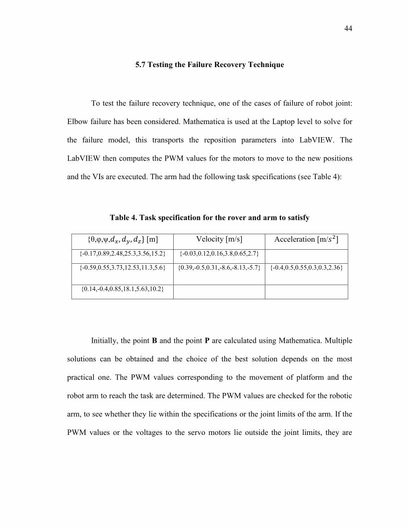
5.7 Testing the Failure Recovery Technique
To test the failure recovery technique, one of the cases of failure of robot joint:
Elbow failure has been considered. Mathematica is used at the Laptop level to solve for
the failure model, this transports the reposition parameters into LabVIEW. The
LabVIEW then computes the PWM values for the motors to move to the new positions
and the VIs are executed. The arm had the following task specifications (see Table 4):
Table 4. Task specification for the rover and arm to satisfy
{θ,φ,ψ, [m] Velocity [m/s] Acceleration [m/
{-0.17,0.89,2.48,25.3,3.56,15.2} {-0.03,0.12,0.16,3.8,0.65,2.7}
{-0.59,0.55,3.73,12.53,11.3,5.6} {0.39,-0.5,0.31,-8.6,-8.13,-5.7} {-0.4,0.5,0.55,0.3,0.3,2.36}
{0.14,-0.4,0.85,18.1,5.63,10.2}
Initially, the point B and the point P are calculated using Mathematica. Multiple
solutions can be obtained and the choice of the best solution depends on the most
practical one. The PWM values corresponding to the movement of platform and the
robot arm to reach the task are determined. The PWM values are checked for the robotic
arm, to see whether they lie within the specifications or the joint limits of the arm. If the
PWM values or the voltages to the servo motors lie outside the joint limits, they are

45
discarded. The joint limits of the robot arm are calculated using VICON motion capture
system.
VICON motion capture system captures the movement of different joints of robot
arm with the help of infrared markers fixed at strategic locations on the joints of the arm
as shown in Figure 20.
Figure 20. Robot arm with infrared markers fixed at different joints
The motion capture system is assembled by three cameras, which note the motion
of the joints, hence monitor its displacement, velocity and acceleration with respect to a
fixed frame. The cameras are set up as in Figure 21. so that the robot arm is placed
within the capture workspace of all the cameras.

46
Figure 21. Set up of infrared detection cameras in VICON motion capture system
The joint limits of the robot arm are given in Table 5.
Table 5. Joint limits of the T-R-T robot arm
Joint Index Joint Minimum Joint Maximum

47
When the PWM values are within the joint limits of the robot, arm receives the
signals from the controller. The platform reaches near the target, when arm remains
unreleased or stowed, when the platform approaches the target close enough, then the
arm is released and the task is performed.
Elbow Actuator/Joint Failure
With the elbow failure, the resulting chain now becomes a T-T chain as shown
in Figure 22. The angle of elbow is fixed at an angle where it fails. In case of our testing,
we simulated the failure of the elbow joint of the robot arm by fixing it at an angle of
Figure 22. Elbow failure in a T-R-T chain

48
The fixing of the elbow joint at that angle, introduces a constraint in the robot
arm, which is a constant distance between the base pivot and the moving pivot through
the equation:
where „R‟ is the distance between the shoulder and the wrist of the T-T chain, is the
distance between the shoulder and the elbow and is the distance between the elbow
and the wrist. is the included angle between the two links. Therefore, once is
fixed at , a constant R can be obtained through the Cosine Law [25].
In case the robot arm loses one of the degrees of freedom i.e. rotation of the
elbow, new parameters for the point B and the point P at the end effector are obtained in
order for the arm to reach the originally specified task.
The reposition parameters for the points B, P and the distance R are calculated
from the failure recovery code in Mathematica using the procedure mentioned in the
previous section. The new reposition parameters are calculated as
. As each of the 5 equations are quadratic for the T-T chain, the
polynomial solution for this system of equations has solutions or 32 solutions. The
solutions whose values lie within the joint limits are chosen, this case has obtained two
real values which lie favorably within the joint limits as shown in Table 6. where the T-
R-T serial chain was able to execute the task despite of the failure in its elbow joint.
(5.1)

49
Table 6. The reposition parameters in case of an elbow failure
Index R(cm)
1 34.034, 12.342 53.453, 2.354, 3.047 16.73 57.3
2 13.426, 16.541 34.231, 8.574, 1.234 14.32 54.6
The robot arm satisfies the given task even with the healthy arm and also with the
crippled arm when the breaks are applied at the failed angle. This failure angle is sensed
by a sensor in practical system. The healthy and crippled configurations of the arm are
shown in the Figures 23 and 24.
Figure 23. Healthy T-R-T serial chain

50
Figure 24. Crippled configuration TT of the TRT
5.8 Summary of the Test
The test for the Failure Recovery synthesis technique which was put forward by
Robson and McCarthy [1] was discussed. To show the practical implementation of this
technique, a Lynxmotion – AL5D robot arm and SMP platform was built. The arm was
integrated onto the front of the platform and both were controlled through NI sbRIO
9632XT, as well as a SSC-32 controller. The simultaneous control of the robot arm and
platform was made possible. The control units are keyboard for the platform and
Logitech –ATK 3 Joystick for the arm. The failure recovery of the arm was

51
demonstrated when the reposition parameters were passed into LabVIEW. This results in
a new position for the base of the platform, the moving point of the arm and a new grasp
point respectively in order for the rover to complete the originally specified task.
5.9 Comments
The present logic for simultaneous control of arm and platform operates in an
open loop, but if the platform and arm operate in a challenging environment,
autonomous navigation is to be considered.
The idea for the closed loop control can be made possible monitoring the
distance moved by the platform. For this purpose, we integrated encoders to all four
motors, which continuously update the count to the controller. Based on these encoder
values, the controller decides which way to go further and supplies the required signals
to the motors of the platform.
At present, we consider two degrees of freedom for the platform. As a result a
two-axis compass HMC 6352 can be integrated. The benefit of this compass can be
largely realized in the ability to make a perfect 90 degree turn from the current position.
This helps us to turn approximately from a given „X-Direction‟ to a given „Y-Direction‟.
Another issue beside the current implementation is the excessive movement of the robot
arm when the platform is in motion, this can be due to the lightweight of the robot arm
used in comparison to the mobile platform. Lastly, the present code considers the base of

52
the platform to be in a plane, but in reality it exists in 3D space, which has to be
accounted for.

53
6. DESIGN OF SPHERICAL MECHANICAL LINKAGES FOR REAL
WORLD APPLICATIONS
The spherical linkages form an important class in Robot manipulators. Some
applications of the design of spherical mechanical linkages for Power Assist and
Cooperative movement of two robotic arms- TS and RRS application is presented below.
6.1 Power Assist Mechanism
The goal of the synthesis of this mechanism is to design a TS chain that provides
power to assist humans to perform repetitive manufacturing operations. This mechanism
can be of a great help in human therapeutic movement or when the humans experience
weakness in their arms due to some health conditions. This mechanism is designed to
guide patient‟s arm through a set of task positions, while satisfying the velocities and
accelerations and along a given trajectory as in Figure 25.
Figure 25. Power Assist for human therapeutic movement

54
The synthesis of this mechanism has certain requirements and specifications:
1. The mechanism is designed for the arm of the worker; TS chain must start and
end at a certain position and follow the trajectory defined by the worker properly
and smoothly. (See Figure 26.)
2. The mechanism discussed here is designed for the right arm of the worker; this
arm is modeled as perpendicular RRS serial chain.
3. The lengths of the upper and lower arm are considered to be of the average
lengths of all humans, i.e. about 29cms.
4. To prevent any untoward incident from happening, the mechanism is so designed
that the body of the worker is taken into account into so called “protected zone”.
Therefore, the trajectory which is to be followed is considered out of the area
which encloses the body.
This protected zone is taken to be a rectangular solid to cover the maximum area.
The coordinates of this rectangular solid are given beforehand while synthesizing the
mechanism.

55
Figure 26. The arm of the worker and mechanism following a specified trajectory
The rectangular body of the worker has the following coordinates, given in the
Table 7. in mm:
Table 7. Vertices of the body of the worker
Vertex 1 Vertex 2 Vertex 3 Vertex 4 Vertex 5 Vertex 6 Vertex 7 Vertex 8
-160 -120 -120 160 -60 -20 -20 -60
30 30 30 30 -100 -100 -100 -100
50 50 -50 -50 -50 -50 50 50
For simplicity, the axis of the TS chain or the pole from which the TS chain
originates is considered about the Z-axis, about (0, 0, 1).
Problem Statement: The trajectory to be followed by the human arm is given. To
synthesize and design a TS chain to follow the same originally specified trajectory, we

56
need to know the parameters B, P and R. The point B is the base point of the TS chain
along the pole; the point P is the wrist point of the TS chain, which is to be gripped by
the RRS chain. The distance R is the distance between this base point B and the wrist
point P. To ensure that the TS chain does not enter the body of the worker, the
coordinates of the body are considered. The movement between the RRS and the TS
arms need to be smooth and also follow the given trajectory smoothly in same point in
space and time.
The human has two tasks to be met in the 3D space, the position, velocity and
acceleration requirements are specified in the Table 8.
The first three parameters in the position requirement specifies the longitude,
latitude and roll parameters to be satisfied, the last three parameters represent the
translational X,Y and Z coordinates. The velocity and acceleration specifications define
the first and second derivatives of these parameters respectively.
Using the synthesis algorithm mentioned in Section 2, we compute the
parameters of the TS chain which satisfies the task requirements. The obtained
parameters B, P and R for the given task are computed and are given in the Table 8.
Table 8. The solutions to the synthesis of TS chain for Power Assist mechanism
B [m] P [m] R [m]
(0.2772, 0.8050,0) (0.101,-0.274,-0.476) 1.876

57
After planning, the animation shows the smooth movement of the arm and the
designed TS chain. The TS chain synthesized is fixed to a pole, the body of the worker is
assumed to be the rectangular portion, and trajectory is given in black, which is the
common trajectory for both the TS and the RRS chains. The set of coordinates which are
the end points of this trajectory represent the two positions which are to be reached by
this system, with the required velocities and accelerations.
6.1 Synthesis of Parallel Mechanical Linkages
The goal of this synthesis is to design a TS chain, based on the inverse
kinematics and path planning of a TRS chain, resulting in a closed loop TRS-TS
mechanism. The task is pretty challenging, since the mechanism is constrained to have
the same Base and Moving pivots. Here the aim of the two arms is not only to follow a
common trajectory but also to have one and the same base pivot.
A task of two positions, two velocities and one acceleration is specified for both
arms, using Vicon 3D motion capture system, available in our Human Interactive
Robotics Lab. The positions, velocities and accelerations, imported from the motion
capture system are given in Table 9. Using the algebraic synthesis procedure described
in Section 2, the TRS and the TS arms have been synthesized for a given fixed pivot
coordinates B = (-0.4563, -0.034, 0). The motion of the TRS mechanism was
synchronized, such that the cooperation is smooth between the arms and the trajectory
was followed by both arms simultaneously in space and time and is shown in Figure 27.

58
The trajectory that the TS chain needs to follow is specified by obtaining the
inverse kinematics of the TRS arm, going through the originally specified task of two
positions, two velocities and one acceleration. Mathematics animations, ensures the
smooth synchronized motion of both arms through the originally specified task. It can be
seen that this structure results in a closed loop parallel TRS-TS mechanical linkage.
Figure 27. Synthesis result of Parallel Mechanical Linkages
B
P

59
The task specification for the above solution is given in Table 9.
Table 9. Task specification for the synthesis of Parallel Mechanical Linkages
Position (m) Velocity (m/s) Acceleration
(m/ )
(0,-90 °,180 ,0.63,3.26,.013) (0,0.1,0.3,0,-0.1,0.1) ------------- ----
(180°,90°,0,0.635,3.27,0.013) (-.1,0,0,-.1,0.01,0) (0,0.1,0,.3,.1,.1)

60
7. CONCLUSIONS AND FUTURE DIRECTIONS
The present research expands on Robson and McCarthy‟s [1], [2] recent works
on synthesis techniques for the joint actuator failure recovery of robot manipulators,
working in remote and challenging environments. Synthesis technique for the design of
spherical mechanical linkages was presented and results were generated using
Mathematica. The practical testing of the failure recovery technique, required an
experimental set up. For this purpose, a Lynxmotion (AL5D) robot arm and the Surface
Mobility Platform (SMP) were integrated into a system. The control logic was written in
LabVIEW using different programs i.e. VIs. Simultaneous control of the robot arm and
platform was obtained. The results of the failure recovery in case of elbow failure were
generated and presented using the real physical system. The applications of the synthesis
of spherical mechanical linkages were demonstrated into the design of Power Assist
Mechanism and the design of parallel kinematic chains.
The research at present has some issues regarding the practical implementation of
the failure recovery logic, specifically in the dynamics of the robot arm and the
consideration of the base point in space. The present tests were conducted in an open
loop control, but for the system to operate in challenging environment, it should have a
feedback mechanism. For this purpose, a HMC 6352 magnetic compass could be
integrated with the encoders to supply the coordinates of the positions of arm and the
platform. The synthesis procedure was considered for the spherical mechanical linkages,

61
which can be further extended to spatial mechanical linkages for use in a six degree of
freedom arm like a TRS robot arm.
At present, only planar, two-dimensional movement for the platform was
considered. As a result a two-axis compass HMC 6352 can be integrated. The benefit of
this compass can be largely realized in the ability to make a perfect 90 degree turn from
the current position.
Another task for future consideration is the excessive movement of the robot arm
when the platform is in motion. This can be due to different reasons, one of which is the
lightweight of the robot arm used in comparison to the mobile platform.

62
REFERENCES
[1] N. Patarinsky Robson, J. M. McCarthy and I. Tumer "Exploring New Strategies
for Failure Recovery of Crippled Robot Manipulators," in ASME/IFToMM
International Conference On Reconfigurable Mechanisms and Robots
(ReMAR’09), London, UK, 2009, pp. 380-385, June 22-24.
[2] N. Patarinsky Robson and J. M. McCarthy, "Kinematic Synthesis with Contact
Direction and Curvature Constraints on the Workpiece," in Proceedings of ASME
International Design Engineering Technical Conferences, Las Vegas, NV, 2007,
pp. 581-588.
[3] D. Tesar and J. W. Sparks, "The Generalized Concept of Five Multiply Separated
Positions in Coplanar Motion," Journal of Mechanisms, vol. 3., pp. 25-33, 1968.
[4] A.G. Erdman, T. Thompson and D.R. Riley, "Type Selection of Robot and
Gripper Kinematic Topology Using Expert Systems," International Journal of
Robotic Research, vol. 5, pp. pp. 183–189 1986.
[5] J. M. Hervé, "The Lie Group of Rigid Body Displacements, A Fundamental Tool
for Mechanism Design," Mechanism and Machine Theory, vol. 34, pp. 719-730,
1999.
[6] H. Tokunaga and S. Imamura, "Constraint Representation Based on Lie Algebra
in Kinematic Model and Synthesis of Mechanisms," Journal of Japan Society of
Precision Engineering, vol. 66(10), pp. 1533-1537, 2000.
[7] T. L. Yang, "Structural Analysis and Number Synthesis of Spatial Mechanisms,"
in Proceedings of the 6th World Congress on the Theory of Machines and
Mechanisms, New Delhi, 1983, pp. pp. 280–283.
[8] Z. Huang and Q. C. Li, "Type Synthesis of Symmetrical-lower Mobility Parallel
Mechanisms Using the Constraint Synthesis Method”, ," The International
Journal of Robotics Research, vol. 22(1), pp. 59-79, 2003.
[9] Y. Fang and L.Tsai, "Structure Synthesis of a Class of 4-DOF and 5-DOF
Parallel Manipulators with Identical Limb Structures," International Journal of
Robotics Research, vol. 21(9), pp. 799-810, 2002.
[10] X. Kong and C. Gosselin, "Type Synthesis of 3T1R 4-DOF Parallel Manipulators
Based on Screw Theory," IEEE Transactions on Robotics and Automation, vol.
20(2), pp. 181-190, 2004.

63
[11] Z. Huang and Q. C. Li, "Type Synthesis of 4-DOF Parallel Manipulators," in
Proceedings of the IEEE International Conference on Robotics and
Automation,Taipei, Taiwan, 2003.
[12] Z. Huang, J. M. Herve and Q. Li, "Type Synthesis of 3R2T 5-DOF Parallel
Mechanisms Using the Lie Group of Displacements," IEEE Transactions on
Robotics and Automation, vol. 20(2), pp. 173-180, 2004.
[13] C. Mavroidis, E. Lee and M. Alam "A New Polynomial Solution to the
Geometric Design Problem of Spatial R-R Robot manipulators Using the Denavit
and Hartenberg Parameters," Transactions of the ASME, vol. 123, pp. 58-67,
2001.
[14] B. Roth, L. Tsai, "A Note on the Design of Revolute-Revolute Cranks,"
Mechanism and Machine Theory, vol. 8, pp. 23-31, 1973.
[15] E. Lee and C.Mavroidis, "Solving the Geometric Design Problem of Spatial 3R
Robot Manipulators Using Polynomial Homotopy Continuation," Transactions of
the ASME, vol. 124, pp. 652-661, 2002.
[16] J. Denavit and R. S. Hartenberg., "A Kinematic Notation for Lower-pair
Mechanisms Based on Matrices," Transactions ASME Journal Applied
Mechanics vol. 22, pp. 215-221, 1955.
[17] M. Spong, M. Vidyasagar, Robot Dynamics and Control, Hoboken, NJ: John
Wiley and Sons, 1989.
[18] L. Saggere and S. Kota, "Synthesis of Planar, Compliant Four-Bar Mechanisms
for Compliant-Segment Motion Generation," Journal of Mechanical Design, vol.
123, pp. 535-541, 2001.
[19] N. M. H. Tokunaga, S. Imamura, F. Tanaka and Kishinami T., "Kinematic
Design of Mechanisms Using Motion Task Formulation and Constraint
Reduction Based on Lie Algebra," Journal of the Japan Society of Precision
Engineering, vol. 123, pp. 608-613, 2002.
[20] J. J. Craig, Introduction to Robotics: Mechanics and Control, Boston, MA:
Addison-Wesley, 1986.
[21] E. Rimon and J. Burdick, "A Configuration Space Analysis of Bodies in Contact
- I. 1-st Order Mobility," Mechanism and Machine Theory, vol. 30(6) pp. 897-
912, 1994.

64
[22] E. Rimon and J. Burdick, "A Configuration Space Analysis of Bodies in Contact
- II. 2-nd Order Mobility," Mechanism and Machine Theory, vol. 30(6), pp. 913-
928, 1995.
[23] S. Chiaverini, O. Egeland, "A Solution to the Singularity Problem for Six-joint
Manipulators," in Robotics and Automation IEEE International Conference,
Cincinnati, OH, 1990, pp. 644-649.
[24] N. P. Robson, J.M. McCarthy and I.Tumer,"The Algebraic Synthesis of a Spatial
TS Chain for a Prescribed Acceleration Task," Mechanism and Machine Theory,
vol. 43, pp. 1268-1280, 2008.
[25] I. A. DeWitt, Fundamentals of Heat and Mass Transfer, 5 ed., Hoboken, NJ:
John Wiley and Sons, 2001.

65
APPENDIX A. ELECTRONIC SPEED CONTROLLERS
An Electronic Speed Control or ESC is an electronic circuit with the purpose to
vary an electronic motor‟s speed, its direction and possibly also act as a dynamic brake.
ESCs are often used on electrically powered radio controlled models.
Figure 28. Electronic Speed Controllers
ESCs are needed for the smooth functionality of the motors. As shown in the
Figure 28., the ESC is made with the four terminals, two for the power and two for two

66
different directions, Dir1 and Dir2. These directions can be checked through the LEDs at
Dir1 and Dir2.
These ESCs are chosen because of their lightweight for the purpose of start up
and shut down of motors.

67
APPENDIX B. NI sbRIO 9632XT – REAL TIME CONTROLLER
This controller was funded by National Instruments Inc. NI sbRIO-9632/9632XT
embedded control and acquisition device integrates a real-time processor, a user-
reconfigurable field-programmable gate array (FPGA), and I/O on a single printed
circuit board (PCB) as in Figure 29. It features a 400 MHz industrial processor, a 2M
gate Xilinx Spartan FPGA,110 3.3 V (5 V tolerant/TTL compatible) digital I/O lines,
32single-ended/16 differential 16-bit analog input channels at 250 kS/s, and four 16-bit
analog output channels at 100 kS/s. It has three connectors for expansion I/O using
board-level NI C Series I/O modules. The sbRIO-9632XT provides an extended
temperature range of-40 to 85 °C with 19 to 30 VDC power supply input range, 128 MB
of DRAM for embedded operation, and 256 MB of nonvolatile memory for storing
programs and data logging.
Figure 29. Ni sbRIO 9632XT
It has a built-in 10/100 Mbits/s Ethernet port used to conduct programmatic
communication over the network and host built-in Web (HTTP) and file (FTP) servers.

68
You also can use the RS232serial port to control peripheral devices. The sbRIO-9632 is
designed to be easily embedded in high-volume applications that require flexibility,
reliability, and high performance

69
VITA
Kapila Bala Phani Neehar received his Bachelor of Technology from Jawaharlal
Nehru Technological University in 2008. He entered the mechanical engineering
program at Texas A&M University in August 2008 and received his Master of Science
degree in August 2011. His research interests include Kinematics of Robots and Control
of Manipulators. He plans to publish a paper on these topics, focusing on Failure
recovery of Robot Manipulators.
Mr. Kapila Bala may be reached at Department of Mechanical Engineering, c/o
Dr. Robson, Texas A&M University, College Station, TX 77843-3123. His email is