the genesis solar wind concentrator: flight and post-flight conditions and modeling of instrumental...
TRANSCRIPT

Space Sci Rev (2013) 175:93–124DOI 10.1007/s11214-013-9961-1
S P E C I A L C O M M U N I C AT I O N
The Genesis Solar Wind Concentrator:Flight and Post-Flight Conditions and Modelingof Instrumental Fractionation
Roger C. Wiens · Daniel B. Reisenfeld · Chad Olinger ·Peter Wurz · Veronika S. Heber · Donald S. Burnett
Received: 8 August 2012 / Accepted: 22 January 2013 / Published online: 19 February 2013© Springer Science+Business Media Dordrecht 2013
Abstract The Genesis mission Solar Wind Concentrator was built to enhance fluences ofsolar wind by an average of 20x over the 2.3 years that the mission exposed substrates tothe solar wind. The Concentrator targets survived the hard landing upon return to Earth andwere used to determine the isotopic composition of solar-wind—and hence solar—oxygenand nitrogen. Here we report on the flight operation of the instrument and on simulationsof its performance. Concentration and fractionation patterns obtained from simulations aregiven for He, Li, N, O, Ne, Mg, Si, S, and Ar in SiC targets, and are compared with mea-sured concentrations and isotope ratios for the noble gases. Carbon is also modeled for a Sitarget. Predicted differences in instrumental fractionation between elements are discussed.Additionally, as the Concentrator was designed only for ions ≤ 22 AMU, implications ofanalyzing elements as heavy as argon are discussed. Post-flight simulations of instrumentalfractionation as a function of radial position on the targets incorporate solar-wind veloc-ity and angular distributions measured in flight, and predict fractionation patterns for var-ious elements and isotopes of interest. A tighter angular distribution, mostly due to better
Electronic supplementary material The online version of this article(doi:10.1007/s11214-013-9961-1) contains supplementary material, which is available to authorizedusers.
R.C. Wiens (�) · C. OlingerLos Alamos National Laboratory, P.O. Box 1663, Los Alamos, NM 87545, USAe-mail: [email protected]
D.B. ReisenfeldDepartment of Physics and Astronomy, University of Montana, Missoula, MT 59812, USA
P. WurzPhysikalisches Institut, University of Bern, Sidlerstrasse 5, 3012 Bern, Switzerland
V.S. HeberDepartment of Earth and Space Sciences, UCLA, 595 Charles Young Drive East, Los Angeles,CA 90095–1567, USA
D.S. BurnettCalifornia Institute of Technology, 1200 California Boulevard, Pasadena, CA 91109, USA
94 R.C. Wiens et al.
spacecraft spin stability than assumed in pre-flight modeling, results in a steeper isotopicfractionation gradient between the center and the perimeter of the targets. Using the dis-tribution of solar-wind velocities encountered during flight, which are higher than thoseused in pre-flight modeling, results in elemental abundance patterns slightly less peakedat the center. Mean fractionations trend with atomic mass, with differences relative to themeasured isotopes of neon of +4.1 ± 0.9 �/amu for Li, between −0.4 and +2.8 �/amufor C, +1.9 ± 0.7�/amu for N, +1.3 ± 0.4 �/amu for O, −7.5 ± 0.4 �/amu for Mg,−8.9±0.6 �/amu for Si, and −22.0±0.7 �/amu for S (uncertainties reflect Monte Carlostatistics). The slopes of the fractionation trends depend to first order only on the relativedifferential mass ratio, �m/m.
This article and a companion paper (Reisenfeld et al. 2012, this issue) provide post-flightinformation necessary for the analysis of the Genesis solar wind samples, and thus serve tocomplement the Space Science Review volume, The Genesis Mission (v. 105, 2003).
Keywords Solar wind · Composition · Solar · Genesis · Cosmochemistry · Solar nebula
1 Introduction
The Genesis mission was proposed and executed to obtain information on the isotopic andelemental composition of the Sun, using the solar-wind as the medium (Burnett et al. 2003).Solar-wind elemental abundances and some isotope ratios have been measured by in-situinstruments, as reviewed, e.g., in Bochsler (2007), Kallenbach et al. (2007), and Wienset al. (2004). However, in order to clearly relate solar and solar-wind isotopic composi-tions to those of other solar-system bodies and to primitive materials remaining from theformation of the solar system, solar-wind isotopic measurements required higher precisionsand accuracies than had been obtained to date. The isotope ratios of volatile elements areof particular interest because they differ between planetary bodies and among meteoritetypes. Oxygen isotope ratios were found to differ by up to ∼ 7 % among planetary pre-cursor materials, displaying non-mass-dependent relationships (e.g., Clayton et al. 1977;Clayton and Mayeda 1984; Clayton 1993; Young and Russell 1998). Several different con-cepts (e.g., Clayton and Mayeda 1984; Thiemens and Heidenreich 1983; Clayton 2002)were put forward to explain this heterogeneity. Each of the theories implied a grossly differ-ent oxygen isotopic composition for the Sun (e.g., Wiens et al. 1999). Nitrogen isotopesalso presented a mystery. But in this case the isotopic heterogeneity was most stronglydisplayed in lunar soils exposed to solar wind (e.g., Kerridge 1993), as well as a fewanomalous meteorites (e.g., Franchi et al. 1986). The presence of widely varying (e.g.,by 20 %) nitrogen isotope ratios in solar-wind-implanted lunar soils suggested that ei-ther the solar wind had itself varied in composition over time, or else another compo-nent was supplying nitrogen ions to the lunar surface (e.g., Wieler et al. 1999). Nitrogenhas only two stable isotopes, so unlike oxygen it is not clear whether mass-dependentfractionation could have produced part or all of the isotopic heterogeneity. More recentmeasurement of nitrogen in the Jovian system (Fouchet et al. 2000; Owen et al. 2001;Atreya et al. 2003) indicated an isotopically light composition relative to the lunar soils.
To address these and other issues the Genesis solar-wind sample return mission wasconceived. The mission was based on the successful Apollo Solar Wind Composition (SWC)experiments in the early 1970s in which foils of aluminum and platinum were exposed tosolar wind for durations of 77 minutes to 45 hours by astronauts on the lunar surface and thenreturned to Earth for analysis (e.g., Geiss et al. 2004). The solar-wind, with energies typically

The Genesis Solar Wind Concentrator: Flight and Post-Flight 95
between 0.5 and 3.5 keV/amu, embeds itself within the top 100 nm of any substrate placedin interplanetary space. The main objective of Genesis was to expose purer substrates in acleaner environment than the dusty lunar surface, and to expose the substrates over ordersof magnitude longer time scales (Burnett et al. 2003). This was best done with a dedicatedspacecraft outside of the Earth’s magnetosphere for a period of years. The materials chosenas collection substrates for the Genesis mission consisted of a variety of semiconductormaterials (Jurewicz et al. 2003).
The Genesis spacecraft was launched in August, 2001. It exposed its substrates for aperiod of 853 days (Reisenfeld et al. 2012) at the L1 Lagrangian point and then returnedthem to Earth. The mission was marred by a failure of the parachutes to deploy during re-entry over the desert in Utah, USA, and the resulting hard landing broke nearly all of thecollectors into smaller pieces. Fortunately, many of these pieces were still usable for manyof the envisioned analyses.
As the mission concept took shape, it became clear that the solar wind is so rarified thatmeasurements of many elements and isotopes would still be very challenging even with farlonger exposures than the lunar SWC experiment. Additionally, some elements tend to beubiquitous contaminants in almost every material on Earth. Oxygen is one such element,as it is a major constituent of the atmosphere and it chemically bonds rapidly with nearlyall solid materials that might be used as collectors. To overcome these two issues, a SolarWind Concentrator was developed which focused ions onto a target to increase the fluenceby a factor of ∼ 20 (McComas et al. 1997; Nordholt et al. 2003), while at the same timerejecting hydrogen, which constitutes more than 95 % of the solar wind ions. Because it isimpossible to accurately mimic the solar wind in a test chamber, a sophisticated computermodel of the instrument was developed to predict its performance in concentrating the ionsand to predict the instrumental fractionation of the ions collected in the target (Wiens et al.2003). Instrumental fractionation, as the term is used here, refers to enhancement of oneisotope or several isotopes in the Concentrator target, relative to these isotope ratios in theunconcentrated solar wind, such as an enhancement of 18O relative to the unconcentratedsolar wind 18O/16O ratio.
The performance of the Concentrator depended significantly on solar-wind charge state,angular distribution, and velocity distribution, even though the Concentrator’s voltages wereadjusted continuously as a function of velocity. As the distributions of some of these pa-rameters vary over the 11-year solar cycle, and other parameters such as solar-wind angulardistribution additionally involve the performance of the spacecraft pointing accuracy, thepre-flight models (Wiens et al. 2003) have been superseded by models using actual flightdata. The post-flight results reported here are substantially different than pre-flight projec-tions, and are of high importance to the science goals of the mission. The following sectionof this paper briefly reviews the Concentrator design. The next section describes the op-eration during flight and the condition of the targets after the capsule recovery. Followingthat is a description of the updated computer model of the instrument and the recent solar-wind parameters as experienced on board the spacecraft by the Concentrator. The Resultssection describes the outcomes of updated performance modeling, including many morecases than were originally undertaken (Wiens et al. 2003). The context of these results isdiscussed, giving reference to experimental work to verify the model results. We concludewith a discussion of (a) the similarities of the N, O, and Ne fractionation patterns, which areimportant to applying the Ne results of Heber et al. (2011) to unknown isotope ratios, and(b) simulations of other elements (e.g., D/H, C, Li, Mg, Si, S) of potential interest for usingConcentrator targets and a discussion of the implications for analyses of new isotope ratios.

96 R.C. Wiens et al.
2 Instrument Description
The Concentrator is radially symmetric with a 41.6 cm diameter aperture at the entranceand a 40 cm diameter parabolic electrostatic mirror that focuses ions onto a target assem-bly 6.2 cm in diameter. Figure 1 shows a cross section of the electrostatic features of theinstrument. The mirror used up to 10 kV potentials to reflect the ions back onto the tar-get. The mirror was micro-stepped to act as a reverse Fresnel lens, reflecting the sunlightdirectly back into space instead of concentrating it on the target (Nordholt et al. 2003).Above the mirror electrode lines of equipotential were held in a parabolic shape by a domedgrid positioned just above the electrode. A hydrogen rejection grid was employed to reduceproton-induced damage to the target assembly. An additional grid accelerated ions througha potential of 6.5 keV/q to straighten their trajectories, making it easier to uniformly focusions incident at a range of angles and energies, and also to implant them farther into thetarget and reduce backscatter losses. The components maintained at −6.5 kV include theacceleration grid, target assembly, domed grid, and a cylindrical “accelerator can” aroundthe perimeter (not shown in Fig. 1), which together formed a field-free cage at the center ofthe instrument, while the grounded grid at the top and the external shell of the instrumentformed a grounded enclosure around the instrument.
The goal of the Concentrator was to enhance by an average factor of 20x the fluence ofsolar-wind oxygen ions of charge states +5 to +8 which constitutes � 99 % of all solar-wind oxygen. The ideal would have been to obtain a homogeneous distribution of solar windacross the entire face of the target. A tightly focused beam does not give this result, so thebeam is necessarily defocused. The degree of defocusing must take into account the angulardistribution of the solar wind and the desires to avoid mass fractionation and maximizethe concentration factor. The final design achieved its average of 20x concentration for thepredicted solar-wind conditions with an acceptable predicted mass fractionation range for18O/16O of approximately 25 permil (�; parts per thousand relative to unconcentrated solarwind) in a relatively slowly varying radial pattern across the target (Wiens et al. 2003).
The Concentrator target assembly was designed to house several different collector mate-rials, following the overall philosophy of exposing a variety of substrates which optimize theanalyses of different elements in the solar wind (Jurewicz et al. 2003). The target assemblywas thus made to house four quadrants of semiconductor material, one of which is shownin Fig. 2. The four quadrants were mounted facing towards the Concentrator’s parabolic ion
Fig. 1 Cross section of the Genesis mission Solar-Wind Concentrator instrument, taken from the SIMIONmodel

The Genesis Solar Wind Concentrator: Flight and Post-Flight 97
Fig. 2 SiC target quadrantsubsequent to disassembly afterflight, shown with dimensions inEnglish and metric units. Lightcolored corners were shielded bythe gold cross support structure.The rest of the target wasdarkened by the exposure to solarwind
Fig. 3 The target assembly as itappeared during disassemblyafter landing. Dimensions of thegold cross and housing are given.The SiC quadrants are at 12-3and 6-9 o’clock. The quadrantbetween them is 13C diamond.The broken quadrant is diamonddeposited on Si. A smallrectangle of bare Si is visible justabove and to the left of the centerof the assembly. Dimensions aregiven in English and metric.Photo NASA JSC
mirror and away from the Sun, in a holder centered on the axis of rotation of the instrument.The four quadrants were held in place by a gold-coated stainless-steel cross, the design ofwhich is illustrated in Fig. 3.
The gold cross was designed as a structural support and was never intended for solar-windanalyses with the possible exception of neon. Nevertheless, it has been used for analyses(e.g., Heber et al. 2011; cf. Marty et al. 2010), prompting questions about its fabrication,described here. No special surface treatments were made to either the stainless steel or thegold to facilitate later analyses. The gold was electroplated on the stainless steel cross andthe target housing at Los Alamos National Laboratory using a standard practice consistingof ultrasonicating with water and detergent, followed by a hot soak in NaOH and then asoak in HCl solution. A nickel strike was applied using NiCl solution electrolysis, and thegold was applied using KAuCN solution electrolysis. Gold-coated aluminum parts of theConcentrator were treated using a standard process consisting of a hot NaOH soak, a nitric-HF bath, sodium zincate, an electrode-less nickel coat provided by a nickel sulfate withsodium hypophosphite bath, and finally the KAuCN solution electrolysis. Pure water rinseswere performed between every step and following the electrolysis. The Ni strike is typically∼ 1.2 µm on Al and less than that on stainless steel. The gold plate itself is 0.5–1.0 µm.

98 R.C. Wiens et al.
Witness plates and spare parts were coated with only the Ni strike or with the completerecipe. X-ray photo-electron spectroscopy (XPS) analyses indicated that traces of K couldbe found on the gold surfaces.
3 Instrument Operation in Flight
The Concentrator mirror electrode and H rejection grid voltages were adjusted every 30 sduring flight, tracking the solar wind proton velocities determined onboard by the GenesisIon Monitor (GIM; Barraclough et al. 2003). The mirror was kept at a multiple of 4.32times the energy per charge at the peak of the proton distribution at all times except whenit reached its maximum potential of 10 kV at a proton velocity of 667 km/s. Between thisvelocity and 800 km/s the mirror remained at 10 kV. The Concentrator was turned off on therare occasions that the solar wind exceeded 800 km/s (3.35 kV/amu) to avoid driving anyof the ions of interest into the mirror. The H rejection grid was kept at a potential between1.0 and 1.3 times the energy per charge at the peak of the proton distribution. This factorwas adjusted based on the temperature of the plasma, such that in hot plasma the H rejectionvoltage was turned down, or even off, to avoid rejecting any of the ions in the m/q ≥ 2.0range (Nordholt et al. 2003).
Because the voltages were commanded based on a running average of three GIM datacycles, the mean time lag between a measured solar wind speed and a Concentrator voltagechange to match was approximately 1.5 GIM data cycles (∼ 4 minutes), or around eightConcentrator data cycles. When comparing voltages of Concentrator 30 s data cycle num-bers differing by eight, one finds that both the mirror and the H rejection grid experiencedfractional voltage changes dV/V of ≤ 1 % fifty percent of the time. For the mirror elec-trode, dV/V reached the 90th percentile in occurrence for a 4 % change. It reached the 99thpercentile for a 10 % change, and the 99.9th percentile for a 17 % change. The operation ofthe Concentrator mirror was designed with a 20 % margin in energy (i.e., would still focusions with 20 % higher energy than the designed-for m/q range at any given instant), and itis clear that the Genesis payload and software were able to perform the integrated task oftracking the solar-wind speed and commanding the proper Concentrator response to easilymeet that margin. Likewise, for the H rejection grid, the 90th percentile was reached at adV/V of 7 %, the 99th percentile by 14 %, and the 99.9th percentile within a 24 % voltagedifference. The H rejection grid operation was planned based on a more complicated func-tion of both the solar-wind speed and temperature, based on mass fractionation calculations.As with the mirror electrode, the rate at which the H rejection grid tracked the solar windvelocity was well within its design margins.
Figure 4 shows the distribution of mirror and H rejection grid voltages during flight.Because the voltage did not track with the solar wind speed above 667 km/s, the mirroroperated at 10 kV a larger fraction of the time than at any other voltage. Aside from this, themirror voltage distribution peaked between 3 and 3.5 kV corresponding to the predominantlow-speed solar wind. The H rejection grid pattern will be discussed in more detail below.
Overall, the instrument concentrated ions over 803.28 days between day 339 of 2001 andday 93 of 2004. The time intervals for the solar-wind Concentrator operation are given inTable S1 in the supporting online information. The Concentrator was turned off by the faultprotection software four times due to a problem with the H rejection grid (described below),for a total of 26.05 days of non-operation. One of those times coincided with the spacecraftgoing into safe mode due to high-energy particles from a solar storm. The Concentrator wasalso turned off for each station-keeping maneuver (total of 6.42 days), for H rejection grid

The Genesis Solar Wind Concentrator: Flight and Post-Flight 99
Fig. 4 Concentrator voltage distributions, for (a) the mirror and (b) the H rejection grid, during collection
tests (0.97 days) and any time GIM was not in autonomous mode or could not determinethe solar-wind speed and temperature, such as during anomalously low density conditions(Barraclough et al. 2003). Additionally, the instrument autonomously turned itself to stand-by whenever the wind speed was consistently above 800 km/s (>600 km/s after 2004 day54). In total, the instrument operated all but 44 days from the start of the Genesis missionscience collection phase until its conclusion.
The H rejection grid was designed for a maximum potential of 3.5 kV. However, it en-countered a problem during turn-on and could not be operated at its full potential. When avoltage was requested above which the grid was stable, the potential dropped to a constantlevel in the 1500–1700 V range and stayed there until a lower voltage was requested. It wasobserved that a higher voltage could be sustained if the grid potential was adjusted upwardsin smaller increments. Software patches were uploaded that limited the voltage increments,and which also lowered the voltage and then returned it to normal if the H rejection grid po-tential dropped below the requested level. To avoid voltage drop-outs, a maximum potentialwas defined in software and was set slightly below the level at which the grid became un-stable. Over the course of the mission the point of instability varied, apparently modulatedby the instrument temperature, which was warmer near perihelia, during the winter monthsin the Earth’s northern hemisphere. The software voltage limit was adjusted periodically todeal with this feature. The software limits used over the course of the collection period areshown in Fig. 5 and are given in Table S3 in the supporting online material. The voltage lim-itation explains the preponderance of 30 second intervals during which the H rejection gridwas at 1.8–2.0 kV, shown in Fig. 4. Without this limitation the maximum incidence wouldhave been at 0.8–1.0 kV, where a secondary peak can be seen. There was also a total of∼ 200 minutes (0.017 % of operation time; too small to be seen in Fig. 4) during which theH rejection grid was turned off completely to avoid isotopic fractionation of heavy ions dur-ing periods of very high plasma temperature (Nordholt et al. 2003). During these intervalsall ions including protons were accelerated towards the mirror and target.
Overall, the H rejection grid maximum voltage limitation is estimated to have increasedthe flow of hydrogen to the target by a factor of ∼ 2.5, with all of the additional hydrogencoming during high speed flows. This raised the maximum fluence to an estimated ∼ 1.5 ×10¹⁷ protons/cm2 near the center of the target assembly.

100 R.C. Wiens et al.
Fig. 5 Maximum Genesis Concentrator H Rejection Grid potential as a function of date
Fig. 6 The condition of theConcentrator as it was extricatedand disassembled at the recoverysite in Utah. The target assemblyis facing away from the camera.Photo NASA JSC
4 Post-Landing Conditions
The Concentrator targets were some of the very few semiconductor materials to survive thecapsule’s hard landing intact (Fig. 3), as the structure of the Concentrator, particularly thestainless steel grid and target supports, cushioned the impact. After the landing the target as-sembly was found near an interior wall of the Concentrator structure (Fig. 6). The quadrantclosest to the wall, the diamond-like carbon-on-silicon (DOS) quadrant, was broken (Fig. 3),apparently from impact with the wall. Much of the material that had broken from that quad-rant was recovered (Rodriguez et al. 2009). Even though the target was nested inside theCapsule, the Sample Canister, and the Concentrator, a couple of spots of Utah mud couldbe seen on the target assembly during disassembly. Additional characterization of surfacecontamination showed that >90 % of the particles are smaller than 5 µm, and most particlesare from the capsule shell and ablator material (Calaway et al. 2008). Extensive photo docu-mentation was made at high resolution by curation personnel for all four of the Concentratorquadrants (e.g., Allton et al. 2008; Calaway et al. 2008).
Prior to integration into the Genesis science canister the Concentrator grids had beencarefully mapped to determine their exact positions, including any departures from the idealshapes. The pre-flight position of the domed grid was used in all subsequent computer sim-

The Genesis Solar Wind Concentrator: Flight and Post-Flight 101
ulations of the instrument performance. Because this was the first solar-wind instrument touse this type of electrostatic grid (i.e., a woven design; Nordholt et al. 2003) and with thelarge aperture, there were significant concerns about thermal relaxation of the grids duringflight. Thermal modeling indicated that the grids would achieve warmer temperatures thantheir frames, potentially leading to wrinkles and/or sagging. Additionally, the thermal massof the grids was so miniscule that they would cool instantly upon being shaded during off-sun maneuvers. The mission plan thus called for the grids to be re-mapped after recovery,and, if the grids had relaxed significantly, for the instrument to be re-tested in a solar-windsimulation facility. The crash made it impossible to determine the amount of relaxation ofthe grids or to estimate their positions during flight. Fortunately, analyses of all four goldcross arms indicated complete radial symmetry during operation (Heber et al. 2011).
Genesis passive solar-wind collectors became coated during flight with a contaminantlayer up to 15 nm thick (Burnett et al. 2005), although it is less than 5 nm on most sam-ples. This material appears to be a polymerized organic, likely from the room-temperaturevulcanizing (RTV) elastomeric sealant used on the array panel fasteners. The compositionwas measured by XPS to be 40–60 % C, 15–40 % O, 2–10 % F, 1–4 % N, and 4–20 % Si(Burnett et al. 2005; Calaway et al. 2006; cf. Schläppi et al. 2010). XPS analyses of one ofthe broken pieces of the DOS Concentrator target quadrant revealed a relatively thin layer ofpolymerized silicone and no detectable F (D. Burnett, personal communication). Ellipsom-etry measurements on SiC quadrant 60003 were modeled to suggest a surface film between4 and 9 nm, though it is unclear if this effect was due to disordering from the radiation dam-age, which was much greater on the Concentrator targets than on the passive collectors, orif it was an actual contaminant layer (Calaway et al. 2007). In any case, the possible layer iswell separated from the bulk of the implanted solar wind, which peaks at a depth of ∼ 80 nmin the Concentrator targets.
Given the presence of contamination on the surfaces of Genesis collectors, it is criticalthat the ions implanted below the surface of the Concentrator target be unambiguously ofsolar wind origin (cf. Becker 2010). A very brief analysis is given here showing that con-taminant ions are not credible as the major source of nitrogen or oxygen implanted in theConcentrator targets. During design and construction of the instrument great care was takento avoid the possibility of contamination. All of the interior surfaces were coated with goldexcept for the grids, their supports, and the insulators. The gold-coated surfaces appearedmostly clean upon return, consistent with the fact that most of them were at relatively hightemperatures (estimated between 150 and 350 ◦C) during collection due to the low emissiv-ity of gold. Contaminants are not likely to condense on surfaces at these temperatures. Theinsulators were recessed wherever possible, so that a minimum of ions would impinge onthem. Insulator surfaces likely to still be exposed to ions were coated with SiC doped withppm levels of nitrogen to provide enough conductivity to bleed any current induced by in-cident ions while being resistive enough to not overload the power supplies (Nordholt et al.2003). The electrostatic grids were not gold coated so as to maximize their transparency(90.44 % each; Nordholt et al. 2003) and also to avoid increasing their temperature duringexposure to sunlight. Because they were not gold-coated, the stainless-steel grids are con-sidered to be the main potential source of any oxygen (or nitrogen) contaminant implantedin the target.
Only particles sputtered from the grids under specialized conditions could have possiblyproduced contamination in the target. Neutral species would not have been implanted intothe target; only ions that were accelerated by the 6.5 kV potential could have been driven intothe interior. Because of their different potentials, not all grids could contribute contaminantions to the target. Any low-energy ions produced by sputtering of the ground grid would
102 R.C. Wiens et al.
be ejected from the instrument by the positive potential of the neighboring H rejection grid(Fig. 1). Low energy ions sputtered from the acceleration grid and domed grid would alsonot be implanted, as they have the same potential as the target. Low-energy ions sputteredinto the interior of the Concentrator from the H rejection grid are the only ones that wouldbe accelerated and implanted into the target. The flux of solar-wind ions striking the Hrejection grid is relatively low, as ∼ 80 % of the protons are rejected by the positive potentialbefore they arrive at the grid. The H rejection grid fractional cross section is 0.0966 forheavy ions and might be slightly higher (e.g., conservatively ∼ 0.2) for protons that wereslowed but not reflected, as these particles may be traveling at a shallower angle relativeto the grid. Given an average solar wind flux of ∼ 3 × 10⁸ protons/cm2/s, 1 × 10⁷ alphaparticles/cm2/s, and 2.5×10⁵ heavier ions/cm2/s, with a mean neutral sputter yield of < 1×10⁻⁴ for low-energy protons (with only a small fraction of their original energy), ∼ 0.1 foralpha particles around 2 keV, and ∼ 1 for heavy ions, approximately 1 × 103 cm−2 s−1 each,of proton-induced and alpha-induced neutrals, and ∼ 2 × 104 cm−2 s−1 heavy ion-inducedneutrals would be produced. Relative to the neutral sputtering yield, the ion sputtering yieldis at most 1 % for the high ionization potentials of O and N considered here. A worst-case approximation would consider the surface of the grid to be pure FeO (50 % oxygen),yielding an upper limit of ∼ 500 O+cm−2 s−1 of contamination impinging on the target.This compares with ∼ 2 × 105 cm−2 s−1 solar wind oxygen ions, giving an upper limit ofoxygen contamination of ∼ 0.25 %. For nitrogen one might assume a maximum of 10 % ofthe species sputtered from the grids are nitrogen which, compared to the solar-wind nitrogenflux, gives a maximum of 0.5 % contamination, but is likely orders of magnitude lower.
To address the potential for radiation damage in the Concentrator targets, test samples oftarget materials were implanted with H at the expected solar wind fluence along with 18Oand 15N in the 1014 cm−2 range. To simulate the solar wind energy distribution the H wasimplanted at three different energies in differing amounts: 50 % at 20 keV, 30 % at 17 keV,and 20 % at 14 keV, all implanted as H+
3 , which is easily produced in the plasma source, withfluences up to 2 × 1017 cm−2. The test samples included SiC from CREE that were identicalto those in the instrument. These samples were heated to various temperatures between 300and 600 ◦C for times ranging from one to six months. Secondary ion mass spectrometry(SIMS) analyses showed no detectable changes in the implant depth distributions of 18Oand 15N, although considerable broadening of the H depth profiles occurred (D.S. Burnett,unpublished data). In addition, a set of H-, 18O-, and 15N-implanted Concentrator targetmaterials were heated in vacuum at the nominal flight temperature (160 °C) for 27 months.These long-term implant samples provide controls accurately simulating of the flight thermalhistory. SIMS analyses of these showed no detectable perturbations to the 18O and 15Nimplant depth distributions.
Numerous analyses of the SiC targets themselves confirm that increased hydrogen flu-ence has not prevented any of the Concentrator analyses to date (Marty et al. 2010, 2011;McKeegan et al. 2011; Kallio et al. 2010; Heber et al. 2011). However, high-resolutionimaging of the diamond-on-silicon target, which has not been analyzed for implanted ma-terial yet, shows widespread blistering on the center half of the target, apparently due toradiation (J. Allton, personal communication).
5 Ion Modeling
In this section we describe the ion optical modeling that was performed subsequent to thelaunch of Genesis, with a view to describing and discussing in this and following sections the

The Genesis Solar Wind Concentrator: Flight and Post-Flight 103
differences from pre-launch projections, comparisons with measurements on some elements,and projections for what to expect on other elements yet to be analyzed.
5.1 Differences between Pre-Flight and Post-Flight Modeling
Extensive ion optical modeling of the instrument was done in the design phase and priorto flight (Wiens et al. 2003) using the SIMION 7.0 package (Dahl 2000). The ion-opticalmodel used an array of 23 million grid points to simulate the structure and interior of theinstrument to a geometrical resolution of 0.67 mm. The model assumed completely flatground, H rejection, and acceleration grids, but it incorporated a map of the pre-launch shapeof the domed grid. All of the grids were modeled as equipotential surfaces, as the grid wiresare much too small to model geometrically. Because the Concentrator operated at differentvoltages depending on the solar wind speed, the model simulated solar wind proton speedsat 100 km/s intervals between 350 and 750 km/s. For each of these five cases, approximatelyone million ions of each isotope were flown, initialized by sampling solar wind angle andcharge-state distributions. As a large fraction of the ions impacted the target at relatively highangles, a backscattering simulation feature was incorporated based on both energy and angleof the ions, using statistical results from the Stopping and Ranges of Ions in Matter (SRIM)code (Ziegler et al. 2010). Simulations were done for 20,22Ne, 16,18O, 4He, and H prior toflight, using the latter two species to determine the nature of possible radiation damageto the target. The model was used to optimize the acceleration voltage and to check forradial asymmetry and other idiosyncrasies, as well as to predict the overall concentration ofspecies and isotopic fractionation as a function of radial position on the target. For the lattertwo parameters, the model yielded only the radial position of each ion impact. The resultsshowed that the Concentrator just met its requirement for an average concentration factorof 20x, though the enhancement was strongly peaked, achieving a factor of over 50x nearthe center, with an enhancement of less than 10x near the edge. The instrumental isotopicfractionation predicted for 18O/16O was confined to a range of just under 25 permil with an18O/16O minimum at a target radius between 15 and 20 mm (Wiens et al. 2003).
More recently the model was improved, facilitated by migrating to SIMION 8.0 on newercomputers. The new model has a resolution of 0.40 mm and uses 110 million grid points tosimulate one quadrant of the instrument (and the rest by symmetry). The new resolutionrepresents a 40 % decrease in inter-grid-point distance, and the new model uses more thanfour times the number of grid points as previously. As in the first model, the field-free regionbetween the acceleration grid and the domed grid is modeled simply by free space. Exten-sive checking was done against the as-built drawings to ensure that the model accuratelyreproduces the flight instrument. The input program used to fly the ions remains largelyunchanged except for the revised input parameters described below.
As mentioned above, the H rejection grid potential was unexpectedly limited duringflight. In post-flight modeling the H rejection grid potential was set 10 % above the kineticenergy of the protons, e.g., 1.1 ∗ (0.5 ∗ mp ∗ v2
p) for the lower three velocity bins (300–400,400–500, and 500–600 km/s). For the highest two velocity bins it was set at 1900 V, which isnear the maximum potential allowed during the mission (Fig. 5). These settings should haveessentially no effect on the ion modeling, as no ions with m/q < 1.5 are discussed here.
The parameters used to simulate ion backscattering at the target were improved signif-icantly. Ions were run in SRIM at 5◦ intervals from 0 to 60◦, and over an energy rangerepresentative of all ions at the target, in up to twelve different energy bins for each angle.For oxygen and neon, 75,000 ions were run per bin, totaling ∼ 50 million ions in over 600runs. The results were fit by using a 3D minimization technique. Backscatter modeling and

104 R.C. Wiens et al.
Fig. 7 Comparison of pre-flightvelocity distribution projectionsand the oxygen velocitydistribution (“O Dist”) obtainedby the ACE SWICS instrumentduring the Genesis solar-windcollection
fitting of He, Li, N, Mg, and Ar into SiC, and C into Si, were done on a similar scale to theO and Ne calculations. In all cases the results were fit by an empirical equation
b = x − y(log(E)
)(1)
where b = percent backscattered, x and y are fourth-order polynomials of the angle in de-grees, and E is the incident ion energy in KeV. The fitted coefficients of x and y are givenin Table S4 in the supporting online material. Argon had a maximum backscatter of <5 %at 60 deg. The maximum backscatter for O was ∼ 8 % under the same conditions, whileHe backscattering was up to ∼ 15 %. Backscattering was not modeled for Si or S becausetheir backscatter fraction is very low relative to the poorer accuracy of the modeling resultsfor these elements, as discussed later. The backscattering correction was done for the otherelements as part of the Monte Carlo simulation program that flies ions into the Concen-trator. Ions that backscattered in the simulation were simply excluded from the resultingdistribution of ions in the target.
5.2 Solar Wind Conditions During Flight
Prior to flight the best estimates of various solar-wind parameters such as velocity, angulardistribution, and charge state distribution were used in the pre-flight modeling (Wiens et al.2003). As will be shown below, small changes in these parameters, particularly for velocityand angular distribution, have a major effect on the performance of the instrument. Becauseof this, it was important to catalogue the in-flight conditions (e.g., Reisenfeld et al. 2012)and to revise the parameters by using actual flight data.
The velocity distribution of solar-wind ions has a significant effect on the overall outcomeof the Concentrator performance in terms of both isotopic fractionation and concentration.The fraction of ions hitting the target drops from 85 to 65 % between 350 and 650 km/s(see supporting online material). The ability of the −6.5 kV acceleration grid to straightenthe trajectories of higher velocity ions is reduced, and these ions are focused less efficientlyonto the target. Figure 7 shows a comparison between the pre-flight estimate and the in-flight data for oxygen, measured by ACE SWICS during the Concentrator operation times.As discussed in Reisenfeld et al. (2012), Genesis encountered significantly more high-speedwind than expected for a long-term average, in part due to the recurrence of a high-speed
The Genesis Solar Wind Concentrator: Flight and Post-Flight 105
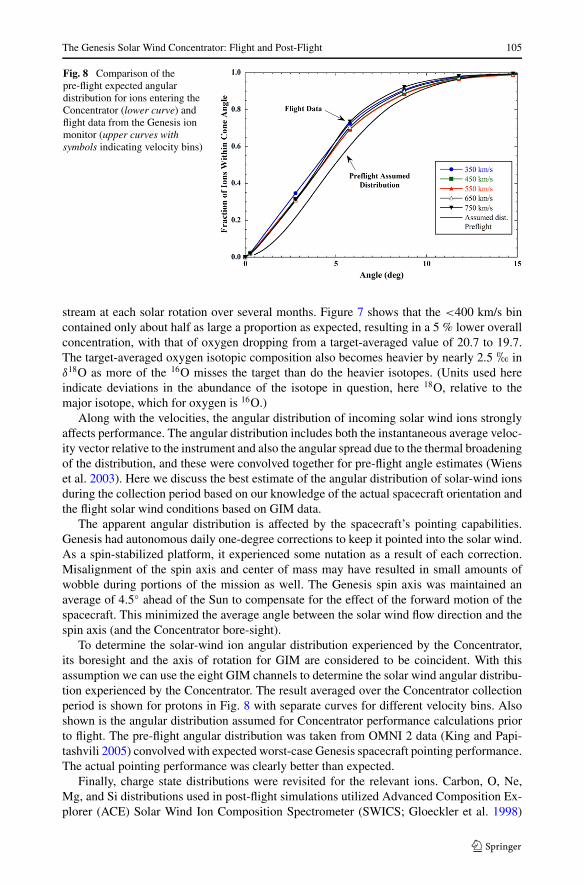
Fig. 8 Comparison of thepre-flight expected angulardistribution for ions entering theConcentrator (lower curve) andflight data from the Genesis ionmonitor (upper curves withsymbols indicating velocity bins)
stream at each solar rotation over several months. Figure 7 shows that the <400 km/s bincontained only about half as large a proportion as expected, resulting in a 5 % lower overallconcentration, with that of oxygen dropping from a target-averaged value of 20.7 to 19.7.The target-averaged oxygen isotopic composition also becomes heavier by nearly 2.5 � inδ18O as more of the 16O misses the target than do the heavier isotopes. (Units used hereindicate deviations in the abundance of the isotope in question, here 18O, relative to themajor isotope, which for oxygen is 16O.)
Along with the velocities, the angular distribution of incoming solar wind ions stronglyaffects performance. The angular distribution includes both the instantaneous average veloc-ity vector relative to the instrument and also the angular spread due to the thermal broadeningof the distribution, and these were convolved together for pre-flight angle estimates (Wienset al. 2003). Here we discuss the best estimate of the angular distribution of solar-wind ionsduring the collection period based on our knowledge of the actual spacecraft orientation andthe flight solar wind conditions based on GIM data.
The apparent angular distribution is affected by the spacecraft’s pointing capabilities.Genesis had autonomous daily one-degree corrections to keep it pointed into the solar wind.As a spin-stabilized platform, it experienced some nutation as a result of each correction.Misalignment of the spin axis and center of mass may have resulted in small amounts ofwobble during portions of the mission as well. The Genesis spin axis was maintained anaverage of 4.5◦ ahead of the Sun to compensate for the effect of the forward motion of thespacecraft. This minimized the average angle between the solar wind flow direction and thespin axis (and the Concentrator bore-sight).
To determine the solar-wind ion angular distribution experienced by the Concentrator,its boresight and the axis of rotation for GIM are considered to be coincident. With thisassumption we can use the eight GIM channels to determine the solar wind angular distribu-tion experienced by the Concentrator. The result averaged over the Concentrator collectionperiod is shown for protons in Fig. 8 with separate curves for different velocity bins. Alsoshown is the angular distribution assumed for Concentrator performance calculations priorto flight. The pre-flight angular distribution was taken from OMNI 2 data (King and Papi-tashvili 2005) convolved with expected worst-case Genesis spacecraft pointing performance.The actual pointing performance was clearly better than expected.
Finally, charge state distributions were revisited for the relevant ions. Carbon, O, Ne,Mg, and Si distributions used in post-flight simulations utilized Advanced Composition Ex-plorer (ACE) Solar Wind Ion Composition Spectrometer (SWICS; Gloeckler et al. 1998)

106 R.C. Wiens et al.
Table 1 C, N, O, Ne, Mg, and Si charge state distributions obtained from ACE/SWICS (Gloeckler et al.1998) data over the Concentrator operation period, used in post-flight simulations. Mean charge state andmass per charge is also noted
Element < 400 km/s 400–500 km/s 500–600 km/s 600–700 km/s 700–800 km/s m/qa
C+4 0.17 0.16 0.19 0.22 0.24 3.3
C+5 0.41 0.41 0.44 0.51 0.54 2.6
C+6 0.42 0.43 0.37 0.27 0.21 2.2
C mean 5.25 5.26 5.18 5.05 4.97 2.6
N+4 0.01 0.01 0.01 0.01 0.01 3.8
N+5 0.96 0.96 0.96 0.96 0.96 3.0
N+6 0.03 0.03 0.03 0.03 0.03 2.5
N mean 5.08 5.08 5.08 5.08 5.08 3.0
O+5 0.02 0.02 0.02 0.02 0.02 3.6
O+6 0.72 0.79 0.87 0.92 0.94 3.0
O+7 0.24 0.17 0.10 0.06 0.04 2.6
O+8 0.02 0.02 0.01 0.003 0.004 2.3
O mean 6.26 6.19 6.11 6.05 6.03 3.0
Ne+6 0.08 0.09 0.11 0.11 0.09 3.7
Ne+7 0.24 0.24 0.26 0.23 0.23 3.1
Ne+8 0.65 0.65 0.62 0.65 0.67 2.8
Ne+9 0.03 0.02 0.01 0.007 0.005 2.4
Ne mean 7.63 7.60 7.54 7.55 7.59 2.9
Mg+6 0.07 0.08 0.08 0.05 0.06 4.3
Mg+7 0.03 0.03 0.05 0.07 0.10 3.7
Mg+8 0.09 0.09 0.12 0.18 0.21 3.3
Mg+9 0.31 0.31 0.33 0.36 0.37 2.9
Mg+10 0.50 0.48 0.41 0.33 0.25 2.6
Mg+11 0.001 0.001 0.000 0.000 0.000 2.4
Mg mean 9.13 9.09 8.96 8.85 8.67 2.9
Si+6 0.05 0.04 0.04 0.03 0.03 5.0
Si+7 0.16 0.15 0.17 0.18 0.18 4.3
Si+8 0.26 0.25 0.27 0.29 0.30 3.8
Si+9 0.28 0.28 0.28 0.30 0.31 3.3
Si+10 0.14 0.15 0.15 0.14 0.14 3.0
Si+11 0.05 0.06 0.04 0.03 0.02 2.7
Si+12 0.06 0.06 0.05 0.03 0.03 2.5
Si mean 8.70 8.78 8.65 8.54 8.52 3.5
aThe m/q column uses the mass of the heaviest isotope. The mean m/q (bold) uses the lowest mean charge
data averaged over the complete Concentrator operation time period, given in Table 1. Oxy-gen distributions are more peaked at +6 (i.e., have slightly lower average charge overall)than those used in pre-flight simulations (Wiens et al. 2003), with the exception of the 700–800 km/s bin, in which the former data relied on Ulysses distributions. Charge states used inrecent modeling for nitrogen (Table 1) are from Gloeckler and Geiss (2007), which in realityrepresents fast polar coronal solar wind, but is here used for all speeds because a represen-
The Genesis Solar Wind Concentrator: Flight and Post-Flight 107
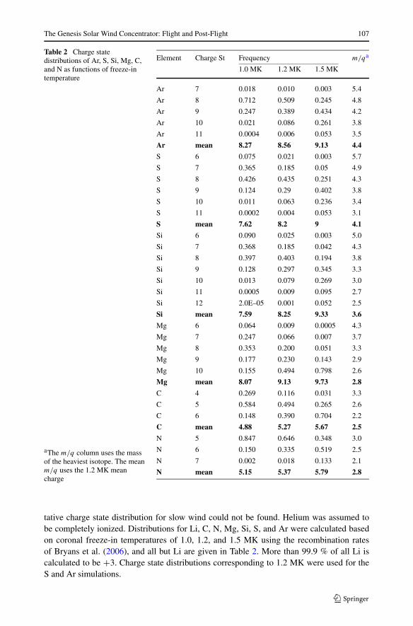
Table 2 Charge statedistributions of Ar, S, Si, Mg, C,and N as functions of freeze-intemperature
aThe m/q column uses the massof the heaviest isotope. The meanm/q uses the 1.2 MK meancharge
Element Charge St Frequency m/qa
1.0 MK 1.2 MK 1.5 MK
Ar 7 0.018 0.010 0.003 5.4
Ar 8 0.712 0.509 0.245 4.8
Ar 9 0.247 0.389 0.434 4.2
Ar 10 0.021 0.086 0.261 3.8
Ar 11 0.0004 0.006 0.053 3.5
Ar mean 8.27 8.56 9.13 4.4
S 6 0.075 0.021 0.003 5.7
S 7 0.365 0.185 0.05 4.9
S 8 0.426 0.435 0.251 4.3
S 9 0.124 0.29 0.402 3.8
S 10 0.011 0.063 0.236 3.4
S 11 0.0002 0.004 0.053 3.1
S mean 7.62 8.2 9 4.1
Si 6 0.090 0.025 0.003 5.0
Si 7 0.368 0.185 0.042 4.3
Si 8 0.397 0.403 0.194 3.8
Si 9 0.128 0.297 0.345 3.3
Si 10 0.013 0.079 0.269 3.0
Si 11 0.0005 0.009 0.095 2.7
Si 12 2.0E–05 0.001 0.052 2.5
Si mean 7.59 8.25 9.33 3.6
Mg 6 0.064 0.009 0.0005 4.3
Mg 7 0.247 0.066 0.007 3.7
Mg 8 0.353 0.200 0.051 3.3
Mg 9 0.177 0.230 0.143 2.9
Mg 10 0.155 0.494 0.798 2.6
Mg mean 8.07 9.13 9.73 2.8
C 4 0.269 0.116 0.031 3.3
C 5 0.584 0.494 0.265 2.6
C 6 0.148 0.390 0.704 2.2
C mean 4.88 5.27 5.67 2.5
N 5 0.847 0.646 0.348 3.0
N 6 0.150 0.335 0.519 2.5
N 7 0.002 0.018 0.133 2.1
N mean 5.15 5.37 5.79 2.8
tative charge state distribution for slow wind could not be found. Helium was assumed tobe completely ionized. Distributions for Li, C, N, Mg, Si, S, and Ar were calculated basedon coronal freeze-in temperatures of 1.0, 1.2, and 1.5 MK using the recombination ratesof Bryans et al. (2006), and all but Li are given in Table 2. More than 99.9 % of all Li iscalculated to be +3. Charge state distributions corresponding to 1.2 MK were used for theS and Ar simulations.

108 R.C. Wiens et al.
Carbon, Mg, and Si charge data are included in both Tables 1 and 2 as a check on the ro-bustness of applying 1.2 MK for the above elements. Comparing the weighted mean chargestates of these elements in Table 1 one sees that the ACE data corresponds very closely to1.2 MK (Table 2) for velocities lower than 500 km/s, but higher velocity bins tend toward alower mean charge. However, the higher velocity charge states are still closest to the meancharges corresponding to 1.2 MK (Table 2). For this reason, charge states correspondingto 1.2 MK were used for all velocity runs for S and Ar. A more comprehensive empiricaltreatment of freeze-in temperatures as a function of solar-wind velocity is compiled in Wurz(2001). In hindsight, for nitrogen, the charge state distribution calculated from the freeze-intemperature of 1.2 MK should probably have been used rather than Ulysses data. Compar-ison of nitrogen in Tables 1 and 2 show the 1.2 MK distribution to include a significantfraction (34 %) of the +6 charge state, while the coronal hole data used consists of almostentirely +5. However, it can be argued that the coronal hole distribution is more likely toproduce an anomalous result, which was not observed.
6 Results
Tables 3 and 4 give the model concentration factors and isotopic fractionations, respectively,relative to the normal solar wind, as functions of the target radius for 5 mm radial bins forall of the elements discussed below. The mean values given at the right side of the tableswere determined from the sums of all ions hitting the target, using a target radius of 31 mmwhen the structure is included (Fig. 3). Table 4 and figures in the remainder of this paperuse a delta (δ) notation which gives the deviations of the ratio of the specified heavy isotopeto the lightest isotope in permil relative to unconcentrated solar wind. The next section
Table 3 Predicted concentration factors for radial bins of the target
0–5 mm 5–10 mm 10–15 mm 15–20 mm 20–25 mm 25–30 mm Ave.
4He 50 46 35 23 13 6.4 19.26Li 51 46 36 23 13 6.5 19.312C in Si 53 48 36 23 12 6.4 19.414N 57 51 38 23 12 6.4 19.616O 56 50 38 23 13 6.5 19.716O no Alfvena 55 50 38 24 13 6.6 19.716O bowed grida 57 51 38 24 13 6.6 19.816O Gaussiana 56 50 38 23 13 6.5 19.716O +8 onlya 55 50 38 24 13 6.6 19.820Ne 58 52 38 24 13 6.4 19.924Mg 57 51 38 23 13 6.5 19.728Sib 58 51 37 23 12 6.4 19.632Sb 55 48 34 20 11 5.7 18.636Ar 52 45 31 18 10 5.2 17.9
Unless otherwise stated, the target is SiCaSpecial cases for oxygen are described in the text. “Alfven” refers to differential heavy ion streaming
bBackscattering was not included, as its effect is relatively small for heavy ions

The Genesis Solar Wind Concentrator: Flight and Post-Flight 109
Table 4 Predicted isotopic fractionations in permil for radial bins of the target
0–5 mm 5–10 mm 10–15 mm 15–20 mm 20–25 mm 25–30 mm Ave. Unc.
δ4He 69 51 29 −21 −49 −41 2.9 0.6
δ7Li 40 30 15 −13 −22 −19 3.8 0.8
δ13C in Si 19 14 4 −13 −15 −10 −1.0 0.6
δ15N 16 15 1 −10 −3 −2 1.6 0.6
δ18O 34 20 2 −15 −9 −4 1.9 0.6
δ18O no Alfvena 33 22 8 −14 −13 −13 2.0 0.6
δ18O bowed grida 29 24 2 −15 −14 −9 1.3 0.6
δ18O Gaussiana 22 21 2 −17 −16 −1 0.0 1.0
δ18O +8 onlya 35 19 6 −13 −10 −7 2.5 0.6
δ22Ne 28 14 −1 −13 −10 −8 −0.6 0.6
δ21Ne 16 7 −1 −6 −5 −5 −0.4 0.6
δ26Mg 8 −1 −17 −27 −26 −21 −15.7 0.6
δ30Sib −4 −5 −19 −26 −29 −18 −18.0 0.8
δ34Sb −14 −38 −45 −55 −53 −47 −44.6 1.2
δ38Ar −43 −51 −73 −77 −77 −68 −66.7 0.9
Isotopic fractionation is given in parts per thousand (permil) deviations from unconcentrated solar wind; theheavy isotope is ratioed to the lightest stable isotope of each element. Unless otherwise stated, the targetis SiC. Statistical uncertainty of each radial bin is in the range of ±1.3 � for central bins to ±2.5 � forinnermost and outermost bins. Calculations assume a uniform SW isotopic composition as a function ofvelocity (see text)aSpecial cases for oxygen are described in the text. “Alfven” refers to differential heavy ion streaming
bBackscattering was not included, as its effect is relatively small for heavy ions
Fig. 9 Comparison of pre-flightand post-flight instrumentalfractionation simulations foroxygen implanted into SiCtargets. Each data pointrepresents the mean of a 5 mmradial strip. Error bars representstatistical uncertainties of themodel results. Dashed linesconnect the data points. The deltavalues plotted on the y-axis arerelative to unfractionated solarwind
compares pre- and post-flight simulations and measured versus model results. Followingthat the results of some variations on the basic model are given, and finally, calculations forHe and Ar concentration are compared with measured results.

110 R.C. Wiens et al.
Fig. 10 Neon measured (Heberet al. 2011) and simulated. As inFig. 9, each simulation data pointrepresents a 5 mm mean
6.1 Comparisons of Oxygen and Neon Between Pre- and Post-Flight Simulations andMeasured
Figure 9 shows a comparison between pre-flight and post-flight modeling of the instrumentfractionation as a function of the radial position on the target for 18O/16O. As in Tables 3and 4, each model data point in Fig. 9 represents a 5 mm radial bin. Simulation conditionsare the same except the post-flight version used SIMION 8.0 with the higher resolution ion-optical model of the Concentrator compared to the SIMION 7.0 model. Also, the velocities,angular distributions, and charge state distributions were revised as noted.
The pre- and post-flight simulations are clearly different, with the post-flight simulationshowing an isotopic fractionation range approximately twice that of the pre-flight simula-tion. Both curves show enrichment of 18O near the center of the target, then a drop to a lowpoint in the 15–20 mm radial bin, and then a rise or leveling off toward the outer edge ofthe target. The difference is for the most part not due to changes in the model, as SIMION7.0 and 8.0 model results were almost statistically indistinguishable when run with the sameinput conditions. Rather, the increasing steepness of the trend from the center is due to thetighter angular distribution used in the post-flight simulation. In the extreme case of a paral-lel beam better focusing is obtained for the heavier ion due to its greater momentum, whichcauses it to reflect closer to the solid mirror electrode surface, while the lighter ion reflectscloser to the domed grid. This grid is stretched across a support structure that forms partof a paraboloid of revolution, but because the grid, under tension, minimizes the distancebetween supports, the resulting surface has a distinct waffle pattern to it (cf. Fig. 6). Theresult is poorer focusing of the lighter ion, and significant fractionation in the case of a verytight angular distribution. In the instrument design, this was balanced against the accelerat-ing potential, which acted to control the angular distribution of the ions as they approachedthe mirror (Nordholt et al. 2003). The pre-flight design was optimized for an acceleratingvoltage of −6.5 kV, given the estimated angular distribution. If the post-flight angular dis-tribution had been anticipated, a slightly lower accelerating potential would have been usedto minimize fractionation.
Figure 10 shows experimentally measured versus post-flight modeled isotopic fraction-ation for 22Ne/20Ne. There are no independent measurements, at this precision, of the iso-topic composition of unconcentrated solar wind oxygen, the element of greatest interest, soit is not possible to experimentally determine the instrument fractionation for that element.However, the solar wind neon isotopic composition was measured both unconcentrated (e.g.,Heber et al. 2009) and in the Concentrator targets, providing a determination of the instru-mental fractionation for that element. We therefore use neon (Heber et al. 2011) for the

The Genesis Solar Wind Concentrator: Flight and Post-Flight 111
comparison in Fig. 10. The measured data are parallel to the simulated data from zero totwenty mm radius, but instead of turning over or leveling off as the simulation predicts, themeasured data continue with nearly the same slope all the way to the outer edge of the tar-get. The difference near the outer edge of the target will be discussed later. Not counting themeasured data point closest to the center of the target (left edge in Fig. 10), which was in theshadow of the target frame (Figs. 2 and 3), the slopes of the simulated and measured datafrom 0 to 20 mm radius are within three percent of each other, well within uncertainty ofbeing identical. Note however, the measured fractionation is consistently 20 permil greaterthan the simulated fractionation in this region.
An important distinction is made between mass-dependent and mass-independent frac-tionation of isotopes, as very different processes in nature are invoked in the two cases.Mass-dependent fractionation affects different isotope ratios of the same element based onthe relative mass differences of the isotopes. For example, a mass-dependent effect will beapproximately twice as strong on 18O/16O as on 17O/16O, with slight second-order differ-ences in mass-dependent effects depending on whether the effect is kinetic or an equilib-rium reaction (e.g., Young et al. 2002). Most of the modeling was done comparing onlytwo isotopes of each element. However, to ensure that the instrumental fractionation ismass dependent, all three isotopes were run for neon, and the velocity-averaged resultsare given in Table 4. Each radial bin is within uncertainty of mass-dependent fractiona-tion. The different velocity bins all follow a mass-dependent fractionation except for thehighest-velocity bin (700–800 km/s), where the fractionation per amu of 22Ne/20Ne was sig-nificantly stronger than that of 21Ne/20Ne. However, the wind in this high-velocity bin didnot contribute much to the total, and so the velocity-averaged neon is well within uncertain-ties of a mass-dependent fractionation overall, consistent with the measurements of Heberet al. (2011). The full neon results and uncertainties are given in Table S6 in the supportingonline material. The effect of the high-velocity bin to the overall modeling will be discussedlater.
6.2 Modeling Variations
Additional features were tested to potentially make the model more realistic. One aspectwas to increase the speed of the ions to account for differential ion-proton streaming. Itis observed that the outflow speed of helium and other heavy ions is usually higher thanthe proton speed (e.g., Marsch et al. 1982; Hefti et al. 1998). This differential streamingis a result of the Alfvén waves carried by the protons pushing the minor ions outward at asignificant fraction of the Alfvén speed, VA (∼ 65 km/s on average at 1 AU). The streamingis limited to a fraction of VA by plasma instabilities in such a manner that ions streamat a greater fraction of VA as the proton speed increases. To investigate this effect on themodel, instead of running the model at 100 km/s intervals between 350–750 km/s, ions wereflown with mean velocities of 368, 475, 580, 686, and 790 km/s while the voltages were setto match proton speeds of 350, 450, 550, 650, and 750 km/s. These speeds are based onACE/SWICS observations of alpha particle differential streaming in the solar wind duringthe Genesis collection period. This feature appeared to result in only a slight differencein the outer radial bin for oxygen, as shown in Fig. 11 by a comparison of instrumentalfractionation curves with and without the differential streaming correction, though it didmake a more substantial difference for Ar, as will be discussed in a later section.
One may also question whether differences in the average direction of streaming betweenprotons and heavy ions have a significant effect on the Concentrator results. An analysis ofthe angular deviation from the radial direction was carried out for protons and alpha particles

112 R.C. Wiens et al.
Fig. 11 Comparison of oxygensimulations with differentfeatures described in the text
based on their temperature spread and the variation in bulk flow direction. For protons thethermal broadening gives a mean angular deviation of 4.9◦ and a flow variation of 3.3◦from radial, resulting in an rms mean of 5.9◦. By comparison, alpha particles showed a4.0◦ deviation from thermal broadening and 2.8◦ in flow variation for an rms mean of 4.9◦.The other heavy ion species studied here should behave similarly to the alphas, and so weconclude that the mean of the angular spread we used (Fig. 8) should be within one degreeof the actual spread, with the modeled spread being slightly wider. This is consistent withthe neon results in Fig. 10, and of the He and Ar results given below, which, if anything,imply a very slightly narrower spread.
Another feature to be tested was a Gaussian velocity distribution. The angular distributionincluding the transverse thermal distribution was already modeled, so only the velocitiesalong the mean flow direction needed to be modified. The following full-width half max(FWHM) velocity dispersions were calculated from ACE/SWICS observations of the He,O, and Fe temperatures during the Genesis collection period and tested with each respectivevelocity bin at ∼ 100 km/s intervals from 350–750 km/s: 20.7, 29.4, 38.8, 54, 68.6 km/s.When used along with the differential streaming correction the instrumental fractionationcurve for oxygen was almost identical to the non-Gaussian simulation (Fig. 11), but with astatistically significant reduction in fractionation in the first bin. As will be discussed laterthe combination of both Alfven velocity and Gaussian features did not appear to fit the argonfractionation pattern.
A final feature to be tested was to modify the shape of the flat grids. As mentioned earlier,these grids were very susceptible to thermal stresses, and because of the condition of theConcentrator after the hard landing it was impossible to determine if these grids had becomeloose in flight. Thermal models of the Concentrator suggested that these grids could havebecome significantly warmer than the bulk of the instrument. The grids and their supportframes were both made of stainless steel so their thermal coefficients of expansion matched.However, the geometry of the fine grid wires may have resulted in higher temperatures.To check for this possibility, a worst-case thermal difference of 150◦ C was assumed, andusing a typical linear expansion rate for stainless steel of 19 ppm/◦C, this would give up to∼ 0.6 mm of slack between the center and the edge. In the worst case this would result in avertical deviation of 2.4 mm in cross section, giving a potential angle of up to 13.5◦ relativeto a flat grid. This was modeled with the 0.4 mm resolution of our SIMION 8.0 model as sixconcentric sections for the acceleration grid, which has by far the strongest effect on the iontrajectories. The instrumental fractionation pattern, determined using heavy ion differentialstreaming, is shown in Fig. 11 to be almost identical to the other cases, this time with aslightly decreased up-turn at the outer edge of the target.
The Genesis Solar Wind Concentrator: Flight and Post-Flight 113
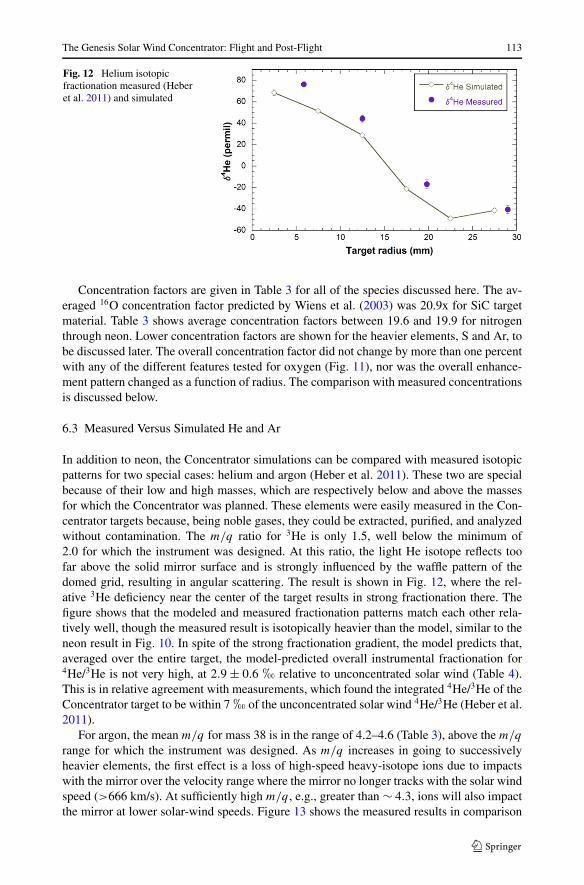
Fig. 12 Helium isotopicfractionation measured (Heberet al. 2011) and simulated
Concentration factors are given in Table 3 for all of the species discussed here. The av-eraged 16O concentration factor predicted by Wiens et al. (2003) was 20.9x for SiC targetmaterial. Table 3 shows average concentration factors between 19.6 and 19.9 for nitrogenthrough neon. Lower concentration factors are shown for the heavier elements, S and Ar, tobe discussed later. The overall concentration factor did not change by more than one percentwith any of the different features tested for oxygen (Fig. 11), nor was the overall enhance-ment pattern changed as a function of radius. The comparison with measured concentrationsis discussed below.
6.3 Measured Versus Simulated He and Ar
In addition to neon, the Concentrator simulations can be compared with measured isotopicpatterns for two special cases: helium and argon (Heber et al. 2011). These two are specialbecause of their low and high masses, which are respectively below and above the massesfor which the Concentrator was planned. These elements were easily measured in the Con-centrator targets because, being noble gases, they could be extracted, purified, and analyzedwithout contamination. The m/q ratio for 3He is only 1.5, well below the minimum of2.0 for which the instrument was designed. At this ratio, the light He isotope reflects toofar above the solid mirror surface and is strongly influenced by the waffle pattern of thedomed grid, resulting in angular scattering. The result is shown in Fig. 12, where the rel-ative 3He deficiency near the center of the target results in strong fractionation there. Thefigure shows that the modeled and measured fractionation patterns match each other rela-tively well, though the measured result is isotopically heavier than the model, similar to theneon result in Fig. 10. In spite of the strong fractionation gradient, the model predicts that,averaged over the entire target, the model-predicted overall instrumental fractionation for4He/3He is not very high, at 2.9 ± 0.6 � relative to unconcentrated solar wind (Table 4).This is in relative agreement with measurements, which found the integrated 4He/3He of theConcentrator target to be within 7 � of the unconcentrated solar wind 4He/3He (Heber et al.2011).
For argon, the mean m/q for mass 38 is in the range of 4.2–4.6 (Table 3), above the m/q
range for which the instrument was designed. As m/q increases in going to successivelyheavier elements, the first effect is a loss of high-speed heavy-isotope ions due to impactswith the mirror over the velocity range where the mirror no longer tracks with the solar windspeed (>666 km/s). At sufficiently high m/q , e.g., greater than ∼ 4.3, ions will also impactthe mirror at lower solar-wind speeds. Figure 13 shows the measured results in comparison

114 R.C. Wiens et al.
Fig. 13 Measured δ38Arcompared with simulations withvarious parameter values:A = 1.5 MK freezing intemperature, Gaussian, no heavyion differential streaming; B =same with 1.2 MK; C = 1.5 MK,heavy ion differential streaming,no Gaussian; D = same with1.2 MK; E = 1.5 MK Gaussian,heavy ion differential streaming;F = same with 1.2 MK
with several different simulations (discussed later). The mean fractionation for the simula-tion that agrees best with the measured data (Heber et al. 2011) is δ38Ar = −67 �, obtainedusing a Gaussian distribution without heavy ion differential streaming and with a chargestate distribution obtained from a 1.2 MK freeze-in temperature.
7 Discussion
7.1 Differences Between Modeled and Measured Results
The main difference between measured and modeled fractionation curves is that the modeledones do not display as large overall ranges as the measurements. The models show slightlylower fractionation in the inner 10 mm, though the trend towards decreasing fractionationseen in the measurements is imitated there. All of the models show a leveling off or slightincreases in the heavy isotopes beyond a radius of 20 mm on the target, which is not ob-served in the measurements of neon (Fig. 10) and helium (Fig. 12; Heber et al. 2011). Thestronger fractionation near the target’s center could likely be imitated in the model by adjust-ing slightly, within uncertainties, towards a tighter solar-wind angular distribution (Fig. 8).The ions implanted in the outer 10 mm of the target have a relatively low concentration (Ta-ble 3) and so they are not as important for solar-wind measurements as the ions implantedin the inner two centimeters (see McKeegan et al. 2011). However, we still wish to knowthe reason for the discrepancy. Each simulation presented in Tables 3 and 4 consists of fivedifferent runs per isotope at different velocities and corresponding instrument potentials. Toobtain the results in these tables the velocity bins are each weighted by the proportion ofsolar wind in each velocity bin determined for oxygen by ACE over the time period theConcentrator was operating. The individual velocity runs are shown for Ne in Fig. 14. Onecan see that they all follow a similar downward trend with increasing radius, but that thelowest velocity bin (350 km/s) shows a very strong positive fractionation towards the outeredge of the target, while the other bins generally level off in the last 10 mm in radius. It islikely that the 350 km/s fractionation is over-emphasized in the overall fractionation patternbecause of the way the velocity bins were defined. Each run was centered over the 100 km/sregion it was to represent. However, this region of velocity space represents the rising edgeof the distribution curve, as most of the ions (70 %) in the 300–400 km/s velocity bin havev > 350 km/s and will in reality behave somewhat more like the 450 km/s curve, which isflat in the outer 10 mm of the target.

The Genesis Solar Wind Concentrator: Flight and Post-Flight 115
Fig. 14 Simulated neonfractionation factors for eachvelocity bin as a function oftarget radius
Fig. 15 Ion angular distributionnear the outer edge of the targetfor 350 km/s oxygen normallyincident on the Concentrator
A second potential reason for differences between the model and measured observationsinvolves electrostatic effects at the edge of the Concentrator. As might be expected fromthe high incidence angles, tracing the ions back to the mirror shows that a large fractionof the ions incident on the outer centimeter of the target come from the outer edges of theConcentrator. Electrostatic instruments like the Concentrator often have boundary-conditioneffects in which the structure outside of the ion flight region affects electric fields in thisregion in ways that are either not well known or are not well modeled. Lower-speed ionsare more susceptible to edge effects, consistent with Fig. 14. We therefore consider it likelythat the difference between predicted and measured fractionation near the edge of the targetis due to edge effects in the instrument itself, magnified by the high angle of incidence ofthese ions on the target (Fig. 15). The discrepancy is not due to the angular distribution ofions as they approach the Concentrator, as a simulation using normally incident ions showsthe same effect in the outer 10 mm of the target.
Finally, we note that the oxygen isotopes (McKeegan et al. 2011, supporting online mate-rial), in contrast to Ne, showed evidence for a leveling off of the isotopic trend for measure-ments made in the outer centimeter of the target, which is consistent with the model resultsfor speeds of 450 km/s and above. However, the relatively large uncertainties render the
116 R.C. Wiens et al.
data also consistent with a slight continued downward trend. Further, there is no compellingreason that the different elements in the same mass range should behave differently.
One additional factor must be considered in comparing simulated and measured fraction-ation patterns. The simulations assume that there is no isotope fractionation between slowand fast solar wind when in fact, a fractionation has been clearly measured for the noblegases from Genesis, at ∼ 63 � for He and ∼ 4.2 �/amu for Ne (Heber et al. 2012). Wienset al. (2003) presented data on the relative contribution of different solar wind velocities todifferent regions of the target. An updated table of these values is given in Table S5 in thesupporting online material. In general the slower speeds are more sharply peaked towardsthe center of the target and contribute by far the most there. When this distribution is con-volved with the observed fractionations mentioned above, they result in ∼ 10 � differencefor δ4He between inner and outer portions of the target, somewhat consistent with the differ-ence at small radial distances in Fig. 12. However, when the observed fast-slow fractionationis applied to other elements the difference is far more subtle, resulting in ∼ 0.5 �/amu dif-ference between the inner and outer portions of the target for Ne, for example.
Concentration factors were reported for He, Ne, and Ar as a function of target radius byHeber et al. (2011). In each case the enhancements 3–6 mm from the center were ∼ 20 %lower than predicted, i.e., with a maximum of 43x compared with predicted concentrationsof 58x and 52x for Ne in the 0–5 and 6–10 mm radial bins (Table 3). The difference betweenmeasured and predicted concentration decreases with increasing target radius, such that theobserved enhancements at r > 20 mm meet the predictions. The reason for the differenceis not clear. During development of the Concentrator significant attention was paid to gridscattering, in which the trajectory of an ion passing very close to a grid wire is bent signif-icantly. However, narrow-beam tests with the instrument yielded sharp beam images on adetector located at the target position, largely ruling out significant grid scattering (Nordholtet al. 2003). At the same time, these tests also yielded beam positions farther from centerthan expected on average, potentially consistent with the current results, but for reasons thatare not clear.
7.2 Fractionation Patterns for Elements Li-Mg in SiC
One question addressed in Heber et al. (2011) was whether the instrumental fractionation ofoxygen and nitrogen is identical to that measured for neon. That question is revisited herein light of the simulations and is extended to other elements including Li and the heavierelements, Mg, Si, and S. For this discussion we ignore the discrepancy in the outer 10 mm oftarget radius while we investigate predicted fractionation differences between the elements.The fact that helium and to some extent argon are relatively well predicted by simulationsgives reasonable confidence for predicting the relative instrumental fractionation of elementsin between these mass ranges. Elements Li through Mg will be discussed first, and then theheavier elements, Si and S will be considered, returning to carbon implanted into silicon atthe end.
Looking at Table 4 and Figs. 10, 12, and 13, it is clear that the lighter elements havesteeper fractionation patterns than heavier elements. However, this difference is due to thelarger relative mass separation for the lighter elements. Figure 16 shows the isotopic frac-tionation patterns in terms of permil/amu (top) and additionally, normalized to the massdifference of the element relative to oxygen (bottom). For example, the 7Li/6Li fractiona-tions in Table 4 are scaled by a factor of 6.5/16.5 and 4He/3He by 3.5/16.5. To first order allof the elements He through Mg now have the same fractionation pattern. In finer detail thereis a minor difference between He and Li on the one hand and the remaining elements. The

The Genesis Solar Wind Concentrator: Flight and Post-Flight 117
Fig. 16 Predicted instrumentalfractionations as a function ofConcentrator target radius for 5mm radial bins. Thefractionations are given inpermil/amu (top) and alsonormalized for relative isotopicmass difference to oxygen(bottom, see text). Error barsprovide statistical uncertainties
similarity between He and Li is a little surprising because their absolute m/q ranges differsignificantly, at 1.5–2.0 for 3He-4He and 2.0–2.3 for Li. However, these two elements havein common a large difference in m/q between their two respective isotopes, which probablycauses the slight difference relative to the heavier elements. One other second-order differ-ence in Fig. 16 is a slightly lower overall trend for Mg. This will be discussed along with Siand S in a later section. Note that the curves in Fig. 16 include corrections due to backscat-tering losses at the target, which is a separate physical phenomenon from the Concentrator’sion optics.
7.3 Prognosis for Deuterium and Lithium
Deuterium was completely destroyed in the early Sun. However, measurements have beenattempted from time to time in order to determine limits on D which may have been con-tributed to the photosphere and solar wind either by late infall of cometary material or byspallation reactions in the corona. Extrapolations of lunar soil measurements placed an upperlimit on solar-wind D/H of < 3 × 10⁻⁶ (Epstein and Taylor 1972, 1973). A recent analysisof unconcentrated Genesis samples found a better upper limit, on the order of < 2 × 10⁻⁷
(Huss et al. 2012). The Concentrator enhances the fluence of D by up to 40x, as its m/q ratiois 2.0, the same as 16O+8, and at the same time the instrument removed about 85 % of theH (m/q = 1.0) with the positive-potential grid. The remaining H has a different abundancepattern on the target, as the low m/q causes the protons to reflect relatively far above themirror electrode where the influence of the waffle pattern of the domed grid tends to scatterthe ions across the target instead of focusing them toward the center. Using a Concentratortarget for a D/H analysis should result in at least a 40x improvement in the D/H upper limit

118 R.C. Wiens et al.
based on the enhancement of D. If the relative reduction of H in the target, particularly nearthe center, also aids in detection of D, the upper limit might be further improved. One wouldneed to correct any result obtained on the target by both the instrumental enhancement ofD and the reduction of H, as well as losses or fractionation due to backscatter at the target,which could be significant.
Lithium represents a very interesting potential observation for solar physics because atsufficient temperatures in the Sun it is depleted, but likely not completely destroyed, byreactions with protons. The minimum temperature for this reaction differs for the two stableisotopes from ∼ 2 × 10⁶ K for 6Li to ∼ 20 % higher for 7Li (e.g., Stix 2004). The standardsolar model may be consistent with complete destruction of solar Li during the pre-main-sequence time when the solar convection zone extended deeper. Photospheric absorption lineobservations provide Li abundance estimates of 1.02 ± 0.12 DEX (Ritzenhoff et al. 1997)and 1.05 ± 0.2 (Baranovsky and Tarashchuk 2008) which are approximately factors of 200below that estimated from meteoritic abundances (e.g., Asplund et al. 2009), consistent withsignificant destruction of Li in the Sun. Using the measured H fluence integrated over theexposure duration of the Concentrator (1.9 × 1016 cm−2), and converting the 1.05 DEX toa Li/H ratio of 1.1 × 10⁻¹¹, the expected unconcentrated Li abundance is 2.1 × 105 cm−2
or a maximum of 6.3 × 10⁵ atoms/cm2 if the solar wind Li/H is enriched by a factor threerelative to photosphere due to the first ionization potential (FIP) effect. The Concentratortarget enriched elements from He to Ne by a factor of 40 in the inner 6 mm radial area (Heberet al. 2011). The current best estimate of the photospheric 6Li/7Li ratio is ≤ 0.03 (Ritzenhoffet al. 1997). Thus expected abundances to be measured in the inner 6 mm of the concentratortarget are up to 2.5 × 10⁷ 7Li/cm2 and ≤ 7.6 × 10⁵ 6Li/cm2, which translates into totalamounts of atoms of 2500 (7Li) and ≤ 76 (6Li) in a 100×100 µm2 raster, a general raster sizeused for SIMS analysis. The relative sensitivity of Li in Si sputtered by an O beam is high,the useful yield (number of ions detected/number of atoms sputtered) is between 10 and50 % (e.g. Wilson 1995). Thus, in principle, using the combined data from numerous rasters,as was done for the much more precise O and N measurements (McKeegan et al. 2011;Marty et al. 2011), a low-precision Li isotopic measurement of Genesis-collected solar windcould be feasible in the innermost area of the concentrator target in absence of Li surfacecontamination, however, it yet has to be tested.
7.4 Heavy Element Analyses
While the Concentrator was originally conceived, designed, and operated for elementslighter than or equal to neon, there is a strong desire to utilize the Concentrator for analysesof heavier elements if possible. Magnesium is a non-volatile, low first-ionization-potentialelement, the isotopic ratios of which are constant to within ±0.04 � for 26Mg/24Mgfor igneous samples and meteorites within the inner solar system (Chakrabarti and Ja-cobsen 2010). It is expected to be incorporated into the Sun without any of the isotopicfractionations seen in volatile elements O (McKeegan et al. 2011) and N (Marty et al.2011). As such, Mg may be the best element to precisely determine solar wind isotopicfractionation (e.g., Kucharek et al. 1997; Kallenbach et al. 1998). Another element ofparticular isotopic interest is sulfur. Given the large scale isotopic differences betweenthe Sun and Earth for volatile elements oxygen and nitrogen (McKeegan et al. 2011;Marty et al. 2011), sulfur, as another volatile element, may also display unexpected iso-topic fractionation. In contrast to N and O, the sulfur isotopic variations in meteorites aremore subtle, in the range of −7.3 � ≤ δ34S ≤ 6.1 � for carbonaceous chondrites, but witha total range of less than one permil for ordinary chondrites and just over two permil forachondrites, as summarized in Rai and Thiemens (2007).

The Genesis Solar Wind Concentrator: Flight and Post-Flight 119
Fig. 17 Predicted sulfur isotopicfractionation as a function oftarget radius for each of thevelocity bins used in thesimulations
It is already clear from an earlier discussion that argon is severely fractionated becauseits mass-to-charge ratio is too high to achieve one hundred percent reflection by the electro-static mirror. The question we address here is whether the Concentrator targets can provideaccurate isotopic results for these elements of intermediate mass between Ne and Ar. Asprovided in Table 2, the mean mass per charge ratio rises quite steeply from Mg (2.8) to Si(3.6) and S (4.1), which is almost as high as that of Ar (4.4).
As mentioned earlier, the mirror’s voltage tracks the kinetic energy of the incoming pro-tons to a speed of 667 km/s, at which point the maximum potential of 10 kV is reached.As the solar wind velocity increases above this point, ions reflect closer and closer to themirror until at some point high m/q ions begin to be lost due to collisions with the mirror.This results in particularly strong isotopic fractionation, as the heavier isotope always has aslightly higher m/q than the lighter isotope. For most of the mission a cut-off proton speedof 800 km/s was used. The highest velocity bin of the simulations (700–800 km/s) is themost susceptible to fractionation for heavy ions, and non-mass-dependent fractionation canresult.
Because of this operational limitation of the Concentrator, the issue of differentialstreaming is important for the heavy ions. However, there appears to be a disagreementwithin the literature and current observations regarding differential streaming of ions heav-ier than neon. On the one hand, some observations (e.g., Schmid et al. 1987; Bochsler 1989;Wurz 2001) clearly indicate that these heavy ions travel more slowly than He, consistentwith no differential streaming relative to protons for the heaviest species, e.g., Si throughFe, at relatively high speeds. On the other hand, data from ACE SWICS over the Concentra-tor collection time period, and in general (Berger et al. 2011), do not indicate any differencesbetween these elements and helium, i.e., with a differential streaming relative to protons. Be-cause it gave the best match for argon (Fig. 13), we modeled Si and S with no differentialstreaming relative to protons.
Figures 17 and 18 show the results for Si and S, respectively, for each velocity bin. It isclear that a significant fraction of the ions are lost from the highest-velocity bin, resultingin increasingly strong fractionation, into the hundreds of permil. For sulfur enough low-charge-state ions are lost from the other velocity bins to pull their mean contributions belowzero permil as well. The resulting mean fractionation given in Table 4 drops to −18.3 ±1.1 � for δ30Si and to −44.6 ± 1.2 � for δ34S, where the quoted uncertainty is merely thestatistical accuracy and does not reflect other potential issues with the model. The overalluncertainty is likely to be on the order of five or up to ten times the statistical uncertainty,based on comparison with the neon and argon measurements. Table 3 shows that, in spite

120 R.C. Wiens et al.
Fig. 18 Predicted siliconisotopic fractionation as afunction of target radius for eachof the velocity bins used in thesimulations
of the isotopic fractionation, the overall concentration factor is reduced by only about 5 %.Thus, it appears possible to use the Concentrator targets to obtain a measurement of the Sisotopic composition in the Sun by correcting the data using the model results reported here.Although the accuracy will not be as good as that of the elements for which the Concentratorwas intended (e.g., O, N, Ne), such a measurement may still be quite useful, as it wouldclearly distinguish solar-terrestrial isotopic differences of the order observed for oxygen(McKeegan et al. 2011) and nitrogen (Marty et al. 2011) with an accuracy better than ±1 %.
Magnesium is an intermediate case between the mass range intended for use and theheavy elements which are clearly fractionated, and here the heavy ion differential stream-ing is critical. Wurz (2001), noting that in his data set the differential streaming drops offsignificantly between oxygen and silicon, interpolated between these elements to predict dif-ferential streaming values of −6, +1, +8, +15, and +22 km/s for Mg at the 350–750 km/sincrements used in the model. These inputs result in relatively minor overall fractionation onthe Concentrator target. The 750 km/s run yielded a mean fractionation of δ26Mg = −38 �,which is considerable, but far less than those of Si, S, and Ar at this speed. A velocity-averaged mean δ26Mg of −3.7 � is obtained, which is only a −1.6 �/amu correctionrelative to the prediction for the carefully-measured neon fractionation (Heber et al. 2011).However, it seems more prudent to use the differential streaming obtained by ACE for thetime period over which the Concentrator was operating, in which Mg appears to streamwith He. Using these velocities, the highest velocity bin is fractionated by −57 �, averagedacross the target. The velocity-averaged results are given in Table 4 for each radial bin, andresults in a spatially averaged value of δ26Mg = −15.7 �. Given the uncertainty in dif-ferential streaming discussed above, the Concentrator targets may not be highly useful fordetermining the precise isotopic composition of solar-wind Mg. Note that the instrumentalfractionation of Mg and the heavier elements including Si and S are likely to be slightlynon-mass-dependent due to the preferential loss of the heaviest ion at the mirror electrodein the high speed wind. Backscatter losses have a negligible effect on the ratios of theseisotopes.
7.5 Carbon Analyses
Carbon analysis in the Concentrator was thought to be impossible due to its presence as amajor constituent in all of the target materials. However, the diamond-on-silicon target (Ju-rewicz et al. 2003) has several small areas in which the diamond-like carbon coating appearsabsent. One such region is seen as a narrow rectangle at the eleven o-clock position in Fig. 3.

The Genesis Solar Wind Concentrator: Flight and Post-Flight 121
Comparison with pre-flight images of the target assembly appears to confirm that this areawas uncoated before the flight, likely due to the position of a clip holding the sample dur-ing carbon coating. Careful inspection of this quadrant indicates surface features consistentwith radiation damage not seen on the SiC quadrants (J. Allton, personal communication).These surface features are strong in the largest bare Si region at 0–10 mm radius (Fig. 3) butdo not appear to be present in another bare region near the outer radial edge of the target.The presence of bare silicon allows the possibility that the Concentrator could be used toanalyze carbon isotopes, likely in the bare region near the perimeter. For this reason, carbonions were modeled as well and the results are given in Tables 3 and 4. The carbon resultswere not included in any of the figures comparing the various fractionation curves due to thefact that this element is modeled in a different substrate, that is, in pure Si.
The carbon results in Table 4 are somewhat surprising in that the fractionation pattern,as well as the target-wide average, is isotopically light compared to what might be expectedfrom interpolation between the lighter and heavier elements, Li, N, and O. All of the dif-ference can be accounted for in the 700–800 km/s velocity bin, the curve for which dropsas low as −37 � for some radial bins. While a relatively small fraction of ions are in thisvelocity bin, it is enough to pull the velocity-averaged fractionation down approximately3 � for each of the radial bins in Table 4, and resulting in a target-averaged fractionation of−1.0 �. The reason is the relatively high fraction of carbon in the +4 charge state for thisvelocity range (24 %; Table 1). The 13C kinetic energy at an incoming velocity of 790 km/s(used to represent the 700–800 km/s velocity bin with differential heavy ion streaming) is42 keV, which at +4 charge is slightly incompatible with the maximum 10 kV potentialof the mirror. Note that N, O, and Ne all have charge states yielding higher m/q values (Ta-ble 1), but the fraction of ions at these charge states is very minor, much less than for carbon.If the carbon is modeled without differential streaming (i.e., using a velocity of 750 km/s torepresent the 700–800 km/s proton velocity bin), the fractionation curve is more as expectedrelative to Li, N, and O, with a target-averaged fractionation of +2.2 ± 0.6 �. The actualvalue expected for carbon is most likely between these two values, as the larger fractionof ions in the 700–800 km/s velocity bin is weighted towards the lower energy side in theabsence of differential streaming. Comparison of the mean fractionation value with theseother elements should provide insight into the expected fractionation relative to He and Nein the bare silicon region, as these elements were measured in equivalent radial positions onanother quadrant (Heber et al. 2011).
8 Summary
Already we can conclude that the Genesis Solar Wind Concentrator has performed well be-yond expectations, particularly in light of the hard landing of the capsule, which preventeda post-flight re-calibration of the instrument or even visual analysis of the grids in the statethey had been during operation in flight. This work explained in detail the features observedin the elements analyzed from its targets to date, and defines the limitations and oppor-tunities that lie ahead for future analyses. In particular, thanks to noble gas measurements(Heber et al. 2011), instrumental fractionation is known with high confidence for all isotopesbetween 3He and 22Ne and may facilitate future analyses of Li and C in the Concentratortargets. Isotopes of S, Si, and to some extent, Mg, are more significantly fractionated bylosses due to impact with the mirror electrode, as corroborated by Ar analyses (Heber et al.2011), but could still be analyzed. Surprisingly, very slight losses appear to affect C in aminor way as well, due to the abundance of its +4 charge state in high-speed wind. The

122 R.C. Wiens et al.
issue of differential fractionation between fast and slow solar wind affects the distributionof helium isotopes on the target, but should have a negligible effect on heavier elements.
Acknowledgements The authors at LANL are grateful for a grant from NASA’s Laboratory Analysis ofReturned Samples (LARS) program, as well as Discovery Program office funding to the Genesis mission.The authors are also grateful to all who made possible the Concentrator experiment, including the Genesisflight. We thank the ACE SWICS instrument team and the ACE Science Center for providing the ACE data.
References
J.H. Allton, M.J. Calaway, M.C. Rodriguez, Preliminary quantification of image color gradient on Genesisconcentrator silicon carbide target 60001. Lunar Planet. Sci. XXXIX, 1440 (2008)
M. Asplund, N. Grevesse, A.J. Sauval, P. Scott, The chemical composition of the Sun. Annu. Rev. Astron.Astrophys. 47, 481–522 (2009)
S.K. Atreya, P.R. Mahaffy, H.B. Niemann, M.H. Wong, T.C. Owen, Composition and origin of the atmo-sphere of Jupiter—an update, and implications for the extrasolar giant planets. Planet. Space Sci. 51,105–112 (2003)
E.A. Baranovsky, V.P. Tarashchuk, Lithium abundances in sunspots. Bull. Crimean Astrophys. Obs. 104,19–25 (2008). Translated from original Russian text in Izv. Krymskoi Astrofiz. Obs. 104, 31–40
B.L. Barraclough, E.E. Dors, R.A. Abeyta, J.F. Alexander, F.P. Ameduri, J.R. Baldonado, S.J. Bame, P.J.Casey, G. Dirks, D.T. Everett, J.T. Gosling, K.M. Grace, D.R. Guerrero, J.D. Kolar, J.L. Kroesche Jr.,W.L. Lockhart, D.J. McComas, D.E. Mietz, J. Roese, J. Sanders, J. Steinberg, R.L. Tokar, C. Urdiales,R.C. Wiens, Genesis electron and ion spectrometers. Space Sci. Rev. 105, 627–660 (2003)
R.H. Becker, Solar wind 15N/14N from Genesis—a tale of two values. Lunar Planet. Sci. XLI, 2469 (2010)L. Berger, R.F. Wimmer-Schweingruber, G. Gloeckler, Systematic measurements of ion-proton differential
streaming in the solar wind. Phys. Rev. Lett. 106, 151103 (2011)P. Bochsler, Velocity and abundance of silicon ions in the solar wind. J. Geophys. Res. 94, 2365–2373 (1989)P. Bochsler, Minor ions in the solar wind. Astron. Astrophys. Rev. 14, 1–40 (2007)P. Bryans, N.R. Badnell, T.W. Gorczyca, J.M. Laming, W. Mitthumsiri, D.W. Savin, Collisional ionizia-
tion equilibrium for optically thin plasmas. I. Updated recombination rate coefficients for bare throughsodium-like ions. Astrophys. J. Suppl. Ser. 167, 343–356 (2006)
D.S. Burnett, B.L. Barraclough, R. Bennett, M. Neugebauer, L.P. Oldham, C.N. Sasaki, D. Sevilla, N. Smith,E. Stansbery, D. Sweetnam, R.C. Wiens, The Genesis Discovery mission: return of solar matter to Earth.Space Sci. Rev. 105, 509–534 (2003)
D.S. Burnett, K.M. McNamara, A. Jurewicz, D. Woolum, Molecular contamination on anodized aluminumcomponents of the Genesis science canister. Lunar Planet. Sci. XXXVI, 2405 (2005)
M.J. Calaway, E.K. Stansbery, K.M. McNamara, Modeling ellipsometry measurements of molecular thin-film contamination on Genesis flown array samples. Lunar Planet. Sci. XXXVII, 1420 (2006)
M.J. Calaway, M.C. Rodriguez, E.K. Stansbery, Genesis silicon carbide concentrator target 60003 prelimi-nary ellipsometry mapping results. Lunar Planet. Sci. XXXVIII, 1632 (2007)
M.J. Calaway, M.C. Rodriguez, J.H. Allton, Genesis Concentrator target particle contamination mapping andmaterial identification. Lunar Planet. Sci. XXXIX, 1423 (2008)
R. Chakrabarti, S.B. Jacobsen, The isotopic composition of magnesium in the inner solar system. Earth Planet.Sci. Lett. 293, 349–358 (2010)
R.N. Clayton, Oxygen isotopes in meteorites. Annu. Rev. Earth Planet. Sci. 21, 115–149 (1993)R.N. Clayton, Self-shielding in the solar nebula. Nature 415, 860–861 (2002)R.N. Clayton, T.K. Mayeda, The oxygen isotope record in Murchison and other carbonaceous chondrites.
Earth Planet. Sci. Lett. 67, 151–161 (1984)R.N. Clayton, N. Onuma, L. Grossman, T.K. Mayeda, Distribution of the pre-solar component in Allende and
other carbonaceous chondrites. Earth Planet. Sci. Lett. 34, 209–224 (1977)D.A. Dahl, SIMION for the personal computer in reflection. Int. J. Mass Spectrom. 200, 3–25 (2000)S. Epstein, H.P. Taylor Jr., O18/O16, Si30/Si28, C13/C12, and D/H studies of Apollo 14 and 15 samples, in
Proc. 3rd Lun. Sci. Conf. (Supplement 3, Geochim. Cosmochim. Cosmochim. Acta) (MIT Press, Cam-bridge, 1972), pp. 1429–1454
S. Epstein, H.P. Taylor Jr., The isotopic composition and concentration of water, hydrogen, and carbon insome Apollo 15 and 16 soils and in the Apollo 17 orange soil, in Proc. 4th Lun. Sci. Conf. (Supplement 4,Geochim. Cosmochim. Acta) (Pergamon, New York, 1973), pp. 1559–1575

The Genesis Solar Wind Concentrator: Flight and Post-Flight 123
T. Fouchet, E. Lellouch, B. Bezard, T. Encrenaz, P. Drossart, H. Feuchtgruber, T. de Graauw, ISO-SWSobservations of Jupiter: measurement of the ammonia tropospheric profile and of the N-15/N-14 isotopicratio. Icarus 143, 223–243 (2000)
I.A. Franchi, I.P. Wright, C.T. Pillinger, Heavy nitrogen in Bencubbin—a light-element isotopic anomaly ina stony-iron meteorite. Nature 323, 138–140 (1986). doi:10.1038/323138a0
J. Geiss, F. Bühler, H. Cerutti, P. Eberhardt, C. Filleux, J. Meister, P. Signer, The Apollo SWC experiment:results, conclusions, consequences. Space Sci. Rev. 110, 307–335 (2004)
G. Gloeckler, J. Geiss, The composition of the solar wind in polar coronal holes. Space Sci. Rev. 130, 139(2007)
G. Gloeckler, J. Cain, F.M. Ipavich, E.O. Turns, P. Bedini, L.A. Fisk, T.H. Zurbuchen, P. Bochsler, J. Fischer,R.F. Wimmer-Schweingruber, J. Geiss, R. Kallenbach, Investigation of the composition of solar andinterstellar matter using solar wind and pickup ion measurements with SWICS and SWIMS on the ACEspacecraft. Space Sci. Rev. 86, 497–539 (1998)
V.S. Heber, R.C. Wiens, A.J.G. Jurewicz, H. Baur, N. Vogel, R. Wieler, D.S. Burnett, Isotope fractionationof solar wind implanted into the Genesis Concentrator target determined by neon in the gold cross andimplantation experiments. Lunar Planet. Sci. XL, 1485 (2009)
V.S. Heber, R.C. Wiens, A.J.G. Jurewicz, N. Vogel, H. Baur, K. McKeegan, R. Wieler, D.S. Burnett, GenesisConcentrator target: isotopic and elemental fractionation of implanted solar wind characterized andquantified by noble gases. Meteorit. Planet. Sci. (2011). doi:10.1111/j.1945-5100.2011.01170.x
V.S. Heber, H. Baur, R. Wieler, P. Bochsler, D.S. Burnett, D.B. Reisenfeld, R.C. Wiens, Fractionation pro-cesses in the solar wind detected by Genesis: He, Ne, and Ar isotopic and elemental composition ofdifferent solar wind regimes. Astrophys. J. 759, 121 (2012). doi:10.1088/0004-637X/759/2/121
S. Hefti, H. Grunwaldt, F.M. Ipavich, P. Bochsler, D. Hovestadt, M.R. Aellig, M. Hilchenbach, R. Kallenbach,A.B. Galvin, J. Geiss, F. Gliem, G. Gloeckler, B. Klecker, E. Marsch, E. Mobius, M. Neugebauer, P.Wurz, Kinetic properties of solar wind minor ions and protons measured with SOHO/CELIAS. J. Geo-phys. Res. 103, 29,697–29,704 (1998)
G.R. Huss, K. Nagashima, D.S. Burnett, A.J.G. Jurewicz, C.T. Olinger, A new upper limit on the D/H ratioin the solar wind. Lunar Planet. Sci. XLIII, 1709 (2012)
A.J.G. Jurewicz, D.S. Burnett, R.C. Wiens, T.A. Friedmann, C.C. Hays, R.J. Hohlfelder, K. Nishiizumi, J.A.Stone, D.S. Woolum, R. Becker, A.L. Butterworth, A.J. Campbell, M. Ebihara, I.A. Franchi, V. Heber,C.M. Hohenberg, M. Humayun, K.D. McKeegan, K. McNamara, A. Meshik, R.O. Pepin, D. Schlutter,R. Wieler, The Genesis solar-wind collector materials. Space Sci. Rev. 105, 535–560 (2003)
R. Kallenbach, F.M. Ipavich, H. Kucharek, P. Bochsler, A.B. Galvin, J. Geiss, F. Gliem, G. Gloeckler, H.Grünwaldt, S. Hefti, M. Hilchenbach, D. Hovestadt, Fractionation of Si, Ne, and Mg isotopes in thesolar wind as measured by SOHO/CELIAS/MTOF. Space Sci. Rev. 85, 357–370 (1998)
R. Kallenbach, K. Bamert, M. Hilchenbach, Isotopic composition of the solar wind inferred from in-situspacecraft measurements. Space Sci. Rev. (2007). doi:10.1007/s11214-007-9216-0
A.P.A. Kallio, K.D. McKeegan, G. Jarzebinski, P.H. Mao, T. Kunihiro, C.D. Coath, V.S. Heber, D.S. Burnett,R.C. Wiens, Nitrogen isotopic composition of solar wind returned by the GENESIS mission. LunarPlanet. Sci. XLI, 2481 (2010)
J.F. Kerridge, Long-term compositional variation in solar corpuscular radiation: evidence from nitrogen iso-topes in the lunar regolith. Rev. Geophys. 31, 423–437 (1993)
J.H. King, N.E. Papitashvili, Solar wind spatial scales in and comparisons of hourly wind and ACE plasmaand magnetic field data. J. Geophys. Res. 110, A02104 (2005). doi:10.1029/2004JA010649
H. Kucharek, F.M. Ipavich, R. Kallenbach, P. Bochsler, D. Hovestadt, H. Grünwaldt, M. Hilchenbach, W.I.Axford, H. Balsiger, A. Bürgi, M.A. Coplan, A.B. Galvin, J. Geiss, G. Gloeckler, K.C. Hsieh, B.Klecker, M.A. Lee, S. Livi, G.G. Managadze, E. Marsch, E. Möbius, M. Neugebauer, K.U. Reiche,M. Scholer, M.I. Verigin, B. Wilken, P. Wurz, Magnesium isotope composition in the solar wind as ob-served with the MTOF sensor on the CELIAS experiment on board the SOHO spacecraft. ESA SP 404,473–476 (1997)
E. Marsch, K.H. Muhlhauser, H. Rosenbauer, R. Schwenn, F.M. Neubauer, Solar wind helium ions: observa-tions of the Helios solar probes between 0.3 and 1 AU. J. Geophys. Res. 87, 35–51 (1982)
B. Marty, L. Zimmermann, P.G. Burnard, D.S. Burnett, R.C. Wiens, V.S. Heber, R. Wieler, P. Bochsler,Nitrogen isotopes in the recent solar wind from the analysis of Genesis targets: evidence for large-scaleisotope heterogeneity in the nascent solar system. Geochim. Cosmochim. Acta 74, 340–355 (2010)
B. Marty, M. Chaussidon, R.C. Wiens, A.J.G. Jurewicz, D.S. Burnett, A 15N-poor isotopic composition forthe solar system as shown by Genesis solar wind samples. Science 332, 1533–1536 (2011)
D.J. McComas, B.L. Barraclough, R.W. Moses, D.S. Burnett, R.C. Wiens, M. Neugebauer, Solar wind con-centrator, in Measurement Techniques for Space Plasmas, ed. by R.F. Pfaff, J.E. Borovsky, D.T. Young.AGU Monograph, vol. 102 (1997), pp. 195–200

124 R.C. Wiens et al.
K.D. McKeegan, A.P.A. Kallio, V.S. Heber, G. Jarzebinski, P.H. Mao, C.D. Coath, T. Kunihiro, R.C. Wiens,J.E. Nordholt, R.W. Moses Jr., D.B. Reisenfeld, A.J.G. Jurewicz, D.S. Burnett, The oxygen isotopiccomposition of the Sun inferred from captured solar wind. Science 332, 1528–1532 (2011)
J.E. Nordholt, R.C. Wiens, R.A. Abeyta, J.R. Baldonado, D.S. Burnett, P. Casey, D.T. Everett, W. Lockhart,D.J. McComas, D.E. Mietz, P. MacNeal, V. Mireles, R.W. Moses Jr., M. Neugebauer, J. Poths, D.B.Reisenfeld, S.A. Storms, C. Urdiales, The Genesis solar wind concentrator. Space Sci. Rev. 105, 561–599 (2003)
T. Owen, P.R. Mahaffy, H.B. Niemann, S. Atreya, M. Wong, Protosolar nitrogen. Astrophys. J. 553, L77–L79(2001)
V.K. Rai, M.H. Thiemens, Mass independently fractionated sulfur components in chondrites. Geochim. Cos-mochim. Acta 71, 1341–1354 (2007)
D.B. Reisenfeld, R.C. Wiens, J.T. Steinberg, J. Raines, T. Zurbuchen, B.L. Barraclough, Solar wind conditionsand composition during the Genesis mission as measured by in situ spacecraft. Space Sci. Rev. (2012).doi:10.1007/s11214-013-9960-2
S. Ritzenhoff, E.H. Schröter, W. Schmidt, The lithium abundance in sunspots. Astron. Astrophys. 328, 695–701 (1997)
M.C. Rodriguez, M.C. Calaway, J.H. Allton, K.M. McNamara, J.D. Hittle, Status of reconstruction of frag-mented diamond-on-silicon collector from Genesis spacecraft solar wind concentrator. Lunar Planet.Sci. XL, 1337 (2009)
S. Schläppi, K. Altwegg, H. Balsiger, M. Hässig, A. Jäckel, P. Wurz, B. Fiethe, M. Rubin, S.A. Fuselier,J.J. Berthelier, J. De Keyser, H. Rème, U. Mall, Influence of spacecraft outgassing on the explo-ration of tenuous atmospheres with in situ mass spectrometry. J. Geophys. Res. 115, A12313 (2010).doi:10.1029/2010JA015734
J. Schmid, P. Bochsler, J. Geiss, Velocity of iron ions in the solar wind. J. Geophys. Res. 92, 9901–9906(1987)
R.M. Skoug, J.T. Gosling, J.T. Steinberg, D.J. McComas, C.W. Smith, N.F. Ness, Q. Hu, L.F. Burlaga, Ex-tremely high speed solar wind. J. Geophys. Res. 109, A09102 (2004). doi:10.1029/2004JA010494
M. Stix, The Sun, 2nd edn. (Springer, Berlin, 2004)M.H. Thiemens, J.E. Heidenreich III, The mass-independent fractionation of oxygen: a novel isotope effect
and its possible cosmochemical implications. Science 219, 1073–1075 (1983)R. Wieler, F. Humbert, B. Marty, Evidence for a predominantly non-solar origin of nitrogen in the lunar
regolith revealed by single grain analyses. Earth Planet. Sci. Lett. 167, 47–60 (1999)R.C. Wiens, G.R. Huss, D.S. Burnett, The solar oxygen isotopic composition: predictions and implications
for solar nebula processes. Meteorit. Planet. Sci. 34, 99–108 (1999)R.C. Wiens, M. Neugebauer, D.B. Reisenfeld, R.W. Moses Jr., J.E. Nordholt, Genesis solar wind concentra-
tor: computer simulations of performance under solar wind conditions. Space Sci. Rev. 105, 601–626(2003)
R.C. Wiens, P. Bochsler, D.S. Burnett, R.F. Wimmer-Schweingruber, Solar and solar-wind isotopic compo-sitions. Earth Planet. Sci. Lett. 222, 697–712 (2004)
R.G. Wilson, SIMS quantification in Si, GaAs, and diamond—an update. Int. J. Mass Spectrom. Ion Process.143, 43–49 (1995)
P. Wurz, Heavy ions in the solar wind: results from SOHO/CELIAS/MTOF. Habilitation thesis, University ofBern, Switzerland, 2001
E.D. Young, S.S. Russell, Oxygen reservoirs in the early solar nebula inferred from an Allende CAI. Science282, 452–455 (1998)
E.D. Young, A. Galy, H. Nagahara, Kinetic and equilibrium mass-dependent isotope fractionation laws innature and their geochemical and cosmochemical significance. Geochim. Cosmochim. Acta 66, 1095–1104 (2002)
J.F. Ziegler, M.D. Ziegler, J.P. Biersack, SRIM—the stopping and range of ions in matter. Nucl. Instrum.Methods Phys. Res. B 268, 1818–1823 (2010)