the gamma ray lens - ompuserpages.irap.omp.eu/~pvonballmoos/gamma_wave_2005/presentatio… · the...
TRANSCRIPT

Science Payloads & Advanced Concepts Office
The Gamma Ray LensTechnology Reference Study
Nicola Rando, Craig Brown
SCI-AM
Corsica - September 2005

Science Payloads & Advanced Concepts Office
ØTechnology Reference Studies
Ø Science Goals
Ø Design Drivers
Ø SF-2B & A5-ECA scenario
Ø Future work - Conclusions
Acknowledgement:
A.Short, A.Lyngvi (SCI-AM) - P.Von Ballmos, H.Halloin (CESR)

Science Payloads & Advanced Concepts Office
¥ Internal ESA exercise carried out by SCI-A Ð system level¥ Hypothetical future missions (not part of ESA science programme)¥ Based on preliminary science goals, used as reference¥ Objectives:
- Essential mission definition / learning tool- Establish technical drivers and requirements- Identify critical technologies for future missions as to construct a
coherent technology development plan
Proved as very useful tool in all space science disciplines(Venus Entry Probe / Jupiter Moon Explorer / Solar Polar Orbiter /
etc.)

Science Payloads & Advanced Concepts Office
Ø First iteration - internal SCI-AM exercise
Ø System level, as to allow preliminary definition
Ø Assuming significant step forward wrt INTEGRAL
Ø Exercise decoupled from programmatic considerations
Ø Emphasis on focusing optics technologies (critical toenhance effective area): maturity & accommodation.

Science Payloads & Advanced Concepts Office
Assumed primary target for the GRL:
SNe Ia 511 keV e+e-
Ø 847 keV line (56Co)
Ø Long rise time ~60 days
Ø Long half life ~77 days
Ø Relatively strong line
Ø Flux ~10-5-10-7 ph.cm-2s-1
Ø Compact Objects
Ø Galactic Binaries
Ø Supernovae
Ø Galactic Centre
Ø Flux ~10-4-10-8 ph.cm-2s-1
Other lines of Interest:158, 481, 812 keV from SNe Ia, 478 keV (Classical Novae),
74, 102 and 170 keV (Compton backscattering)

Science Payloads & Advanced Concepts Office
10 yearNom. Mission Lifetime
30¼ half cone (based on XEUS)Sun Restraint Angle
~ 106 s @ 511 keV, 2x10⁵ s for SNe IaTypical Integration Time
~ 10-8 ph.cm-2s-1keV-1Continuum Sensitivity
~ 5x10⁻⁷ ph.cm-2s-1Line Sensitivity
2 keV @ 600 keVEnergy Resolution
Arc-minuteAngular Resolution
~ 10000 cm2 @511 keV, 5000 cm2 @ 847 keVEffective Area
425-522 keV, 825-910 keV, 50-200 keVEnergy Band
RequirementParameter
Ø Target established from catalogued position (e.g INTEGRAL), from orbit or ground based observations.
Ø Imaging not a priority Ð point sources (tbc) Ð time evolution of fluxes + spectroscopy
ESLAB symposium

Science Payloads & Advanced Concepts Office
Ø Laue Crystals:Ø Capable of higher energies Ð truly in the gamma ray regime àààà key technology
Ø Small energy band-pass (~ 60 keV) àààà suited for line emission, not for continuum
Ø Very small FOV (~ 30ÕÕ) àààà more suited for point sources, not for imaging
Ø Graded Multilayer Mirrors:
Ø Capable of larger energy band-pass Ð Potential interest for continuum emission
Ø Advanced coatings applied to existing optics geometry, e.g. XMM-Newton, XEUS
Ø Efficient at hard XÐray energies (< 200 keV at present stage)
Focusing optics

Science Payloads & Advanced Concepts Office
Ø Laue lens assemblyCrystals mounted in concentric rings - Each crystal ring focuses a different peakenergy to the focal point Ð R ~ 3 to 5 m (depending on LV fairing)
Large number of crystals, crystal alignment, large mass, deployable structure
Ø Formation flying:Imposed by long focal distance of focusing optics (f ~ 500 m )
Relaxed ACS requirements wrt VIS/NIR optics (+/- 1cm lateral, +/- 50 cm on axis)
Ø Focal plane:Spectrometer (imaging assumed to be lower priority) Ð not requiring cryogenics
High energy resolution and stopping power Ð radiation hard
Pixellated detector to improve background rejection Ð anticoincidence system

Science Payloads & Advanced Concepts Office
Ø Effective Area & Sensitivity model created (Laue)
Ø 2 different scenarios investigated (both at L2):
Ø Soyuz-Fregat (2B)
Ø Ariane 5 (ECA)
Ø Preliminary analysis of both scenarioÕs
Ø Ariane 5 scenario chosen for further investigation
Ø Further spacecraft definition and mass budgeting
Ø Further work required and potential TDAs extracted

Science Payloads & Advanced Concepts Office
Ehc
FRd
)2tan(R
F
Ehc
nsind2
B
B
====∴∴∴∴
θθθθ====
====θθθθ
RdFhc
E
FR
2
Ehc
d2
B
B
====⇒⇒⇒⇒
====θθθθ⇒⇒⇒⇒
====θθθθ⇒⇒⇒⇒Forsmall_B andn=1
Ø Crystalsmounted inconcentric rings
Ø 2 energy bands over~70 rings (Ge + Cu)
Ø Each crystal ringfocuses a differentpeak energy to thefocal point
R1
R2
R3
_B2
_B1 _B1 > _B2

Science Payloads & Advanced Concepts Office
Main assumptions:
- Background as INTEGRAL/SPI
- Ge detector: δδδδE = 0.4% FWHM
- Detector thickness = 3 cm
- Integration time: 10^6 sec
- PSF radius = 1 sigma
Validated reproducing MAX results(reported at Integral workshop 2005)

Science Payloads & Advanced Concepts Office
Effective Area Sensitivity
Science Payloads & Advanced Concepts Office
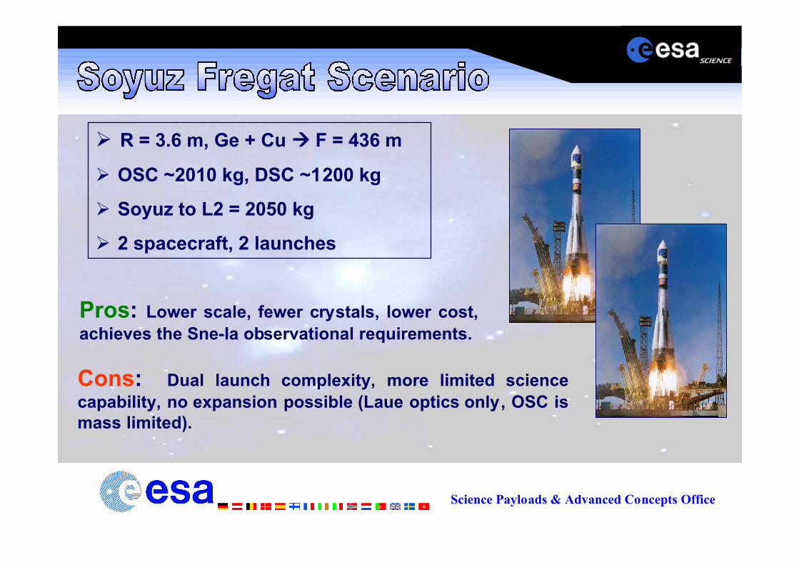
Ø R = 3.6 m, Ge + Cu àààà F = 436 m
Ø OSC ~2010 kg, DSC ~1200 kg
Ø Soyuz to L2 = 2050 kg
Ø 2 spacecraft, 2 launches
Pros: Lower scale, fewer crystals, lower cost,achieves the Sne-Ia observational requirements.
Cons: Dual launch complexity, more limited sciencecapability, no expansion possible (Laue optics only, OSC ismass limited).

Science Payloads & Advanced Concepts Office
Ø R = 4.5m, Ge + Cu àààà F = 504 m
Ø OSC ~3600 kg, DSC ~1300 kg, Tot = 4900 kg
Ø A5 to L2 = 6800 kg (ECA)
Ø 2 spacecraft, single launch
Pros: All science requirements met. Significant scopefor payload expansion Ð either increased effective area orincreased bandwidth. Also addition of other payloads.Simpler operations through single launch.
Cons: larger cost, larger # of crystals, more complex deployment mechanism

Science Payloads & Advanced Concepts Office
SF : Aeff ~7400 cm2 @ 511 keV, ~4800 cm2 @ 847 keV
S ~ 1-2 x 10⁻⁷ ph.s-1cm-2 (3 sigma)
A5 : Aeff ~10800 cm2 @ 511 keV, ~6400 cm2 @ 847 keV
S ~ 7 x 10⁻⁸ to 1 x 10⁻⁷ ph.s-1cm-2 (3 sigma)
Includes Graded Multi-layers Optics for 50-200 keV range
Significant opportunity for P/L expansion
A5 scenario selected for additional TRS work

Science Payloads & Advanced Concepts Office
Diameter of bus to accommodate this.2624 Ariane 5 adapter
¥ GaAs and Si solar panels providing adequate powerin all orientations
¥ Omni-directional communication capability
No direct sunlight on the Ge detectors
30¡ sun angle restriction duringobservation
Bus is a cylindrical ring with the Graded Multi-layerOptics (GMO) supported inside
Unobstructed Graded Multi-layersoptics (additional lens)
MLI covering the Laue lens and Silicon Pore Optic,complemented by active temperature control
Temperature gradient &misalignment control of the optics
Support/stiffening rings used before deploymentduring launch
Large mass concentration on thelens ring
Novel deployment mechanism Ð folded and locked on
long, cylindrical spacecraft bus
Deployment mechanism for thelarge diameter circular lens
Design SolutionConfiguration Design Driver

Science Payloads & Advanced Concepts Office
Ø 9m diameter lens
Ø 184988 Ge crystals
Ø 64582 Cu crystals
80 %P.F.
Ø Additional Graded Multilayer Optics
Ø More passive of the 2 spacecraft
Ø 3 Axis stabilised
Ø Omni-directional com with DSC
Ø Crystals and GMO covered in MLI

Science Payloads & Advanced Concepts Office
Ø Design drivers
Ø Segmented in petals (30)
Ø Inter-crystal alignment
Ø AIV/AIT, calibration facility
Ø Large mass (launch lock)
Ø Minimise T gradients toavoid lens distortion (MLI)
Ø Simple spring-latch
Dedicated study is required

Science Payloads & Advanced Concepts Office
Low impact on S/C configuration Ð unitsdistributed on module.
Formation Flying equipment
Radiator panel positioned on a wall whichwill continuously face cold space
Cryogenic system requires heatdissipation
2624 adapter used to optimise the launchload path via Internal cylindrical wall
Supporting the OSC in the Stackconfiguration
Height of bus driven by this. Positioned inthe centre of the spacecraft
Large primary payload detector
Design SolutionConfiguration Design Driver

Science Payloads & Advanced Concepts Office
Ø More active of the 2 spacecraft (FF)
Ø Designed for launch stack configuration:
Ø Diameter and strength to support theOSC during launch
Ø Inner cylindrical wall tooptimise load path
Ø Payload is a spectrometer based on SPI INTEGRAL
Ø 52 Ge detectors @80K and 405cm2, BGO ACS.

Science Payloads & Advanced Concepts Office
Dev. of rad hard detectors,LaI, LuI
10 yeas (+) desiredMissionLifetime
Crystal mounting, deployment& thermal design/analysis
Mosaicity, alignment, thermalcontrol
PSF SizeAddress AIV/T, test facilitiesCalibration / alignment of
lensMetrologySystem
Establish formation flyingpackage, including DSCpropulsion issues
AOCS designFormationFlying &Rendezvous
Polarisation techniques,detector design
Noted as highly desirable bythe Gamma-ray sciencecommunity
Polarisation
Development of ACS materials(e.g LYSO & LuAP)
ÔBetterÕ ACS detectors,designing out intrinsic linesfrom S/C
BackgroundRejection
Design and characterisationof the Optics and multi-layers, Aeff
Optics development,multilayer coating design for50-200 keV
Graded Multi-layer Optics(e.g. SiPO)
Crystal growth / large scalefabrication / mountingtechniques
Crystal growth,characteristics, mounting,packing factor, alignment
Laue CrystalsFuture WorkDriverKey Mission
Science Payloads & Advanced Concepts Office
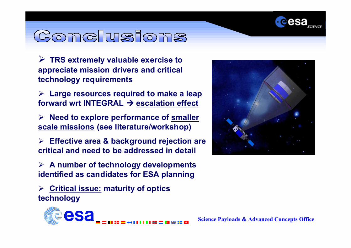
Ø TRS extremely valuable exercise toappreciate mission drivers and criticaltechnology requirements
Ø Large resources required to make a leapforward wrt INTEGRAL àààà escalation effect
Ø Need to explore performance of smallerscale missions (see literature/workshop)
Ø Effective area & background rejection arecritical and need to be addressed in detail
Ø A number of technology developmentsidentified as candidates for ESA planning
Ø Critical issue: maturity of opticstechnology