the future of ctf3
TRANSCRIPT
1
R. Corsini – The future of CTF3, 30/1/2015 CLIC Workshop 2015
The future of CTF3
R. Corsini
05/01/2023
2
R. Corsini – The future of CTF3, 30/1/2015 CLIC Workshop 2015
05/01/2023
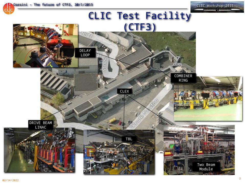
DRIVE BEAM LINAC
COMBINERRING
CLIC Test Facility (CTF3)
DELAY LOOP
CLEX
TBL
Two Beam Module

3
R. Corsini – The future of CTF3, 30/1/2015 CLIC Workshop 2015
05/01/2023
High current, fullbeam-loading operation
Operation of isochronous lines and rings
Bunch phase coding
Beam recombination & current multiplication by RF deflectors
12 GHz power generation by drive beam deceleration
High-gradient two-beam acceleration
PETS ON/OFF
4 A, 1.4us120 MeV
30 A, 140 ns120 MeV
30 A, 140 ns60 MeV
CLIC Test Facility (CTF3)
4
R. Corsini – The future of CTF3, 30/1/2015 CLIC Workshop 2015
05/01/2023
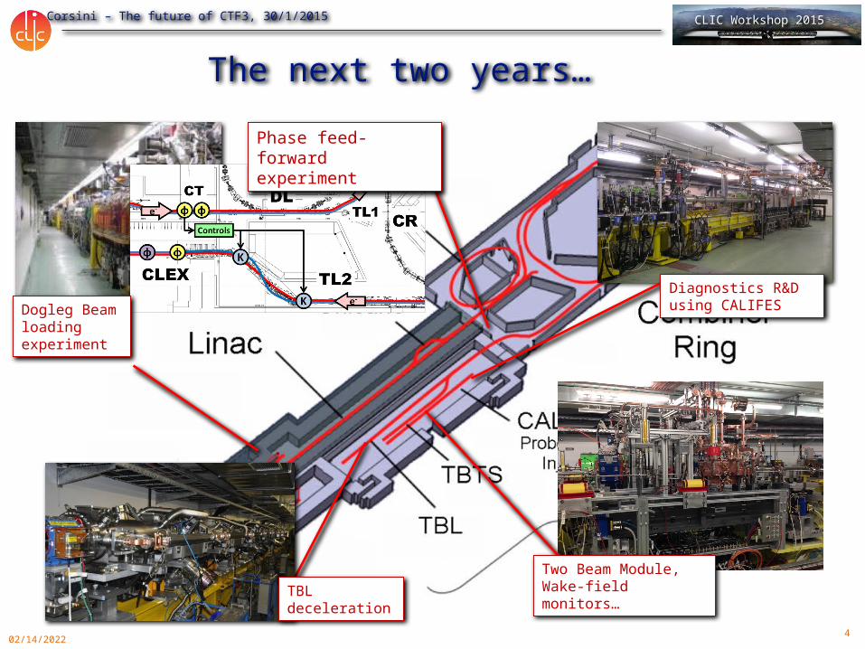
The next two years…
TBL deceleration
Two Beam Module,Wake-field monitors…
Dogleg Beam loading experiment
Phase feed-forward experiment
Diagnostics R&D using CALIFES
5
R. Corsini – The future of CTF3, 30/1/2015 CLIC Workshop 2015
05/01/2023
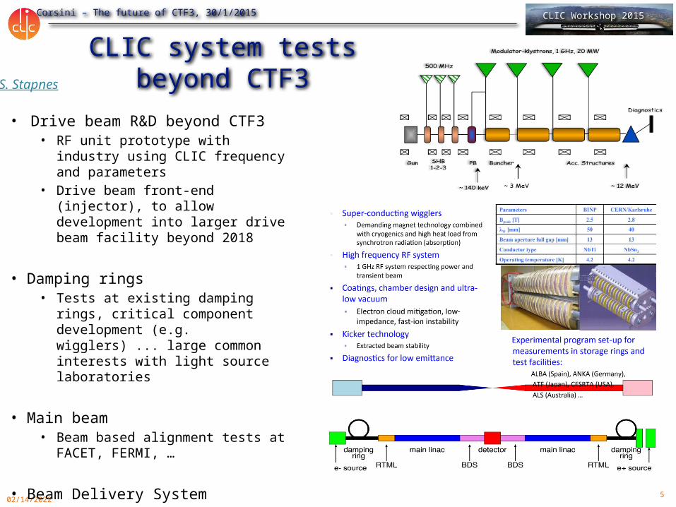
CLIC system tests beyond CTF3
• Drive beam R&D beyond CTF3 • RF unit prototype with industry
using CLIC frequency and parameters
• Drive beam front-end (injector), to allow development into larger drive beam facility beyond 2018
• Damping rings• Tests at existing damping rings,
critical component development (e.g. wigglers) ... large common interests with light source laboratories
• Main beam • Beam based alignment tests at
FACET, FERMI, …
• Beam Delivery System • ATF/ATF2
S. Stapnes

6
R. Corsini – The future of CTF3, 30/1/2015 CLIC Workshop 2015
Context• CTF3 went well beyond its initial task of demonstrating CLIC
two-beam scheme feasibility• Has a well established scientific program until end 2016
• Definitely want to stop CTF3 after that (limited resources…) What to do with CTF3 hardware & building?
• Discussions started beginning 2014. Current main proposals:
Install new DB front-end in CTF3 linac area (CLIC related).
Keep using CALIFES linac in CLEX for as a general test facility after 2016. Possibly interesting beyond CLIC scope (in CERN and outside).
Last discussions at LCWS 2014 – Belgrade & CLIC Project Meeting:https://agenda.linearcollider.org/event/6389/session/18/#20141009http://indico.cern.ch/event/356495/
05/01/2023
7
R. Corsini – The future of CTF3, 30/1/2015 CLIC Workshop 2015
05/01/2023
Rationale for uses of CTF3 hardware beyond 2016
• CLIC Collaboration interest: keep beam test capability for CLIC (diagnostics, components…) locally at CERN after CTF3 stop
• Some additional points:
• Possibility of beam tests during long shut-downs• Keep experimental electron expertise alive at CERN, including laser and
photo-cathodes – link with AWAKE• Complement high-gradient X-band activities for X-FELs, medical…• Provide training ground for young accelerator physicists at CERN and
collaborating institutes
Find synergies with other potential partners (project/groups within and outside CERN) in order to gather enough resources and get approval from CERN management
8
R. Corsini – The future of CTF3, 30/1/2015 CLIC Workshop 2015
05/01/2023
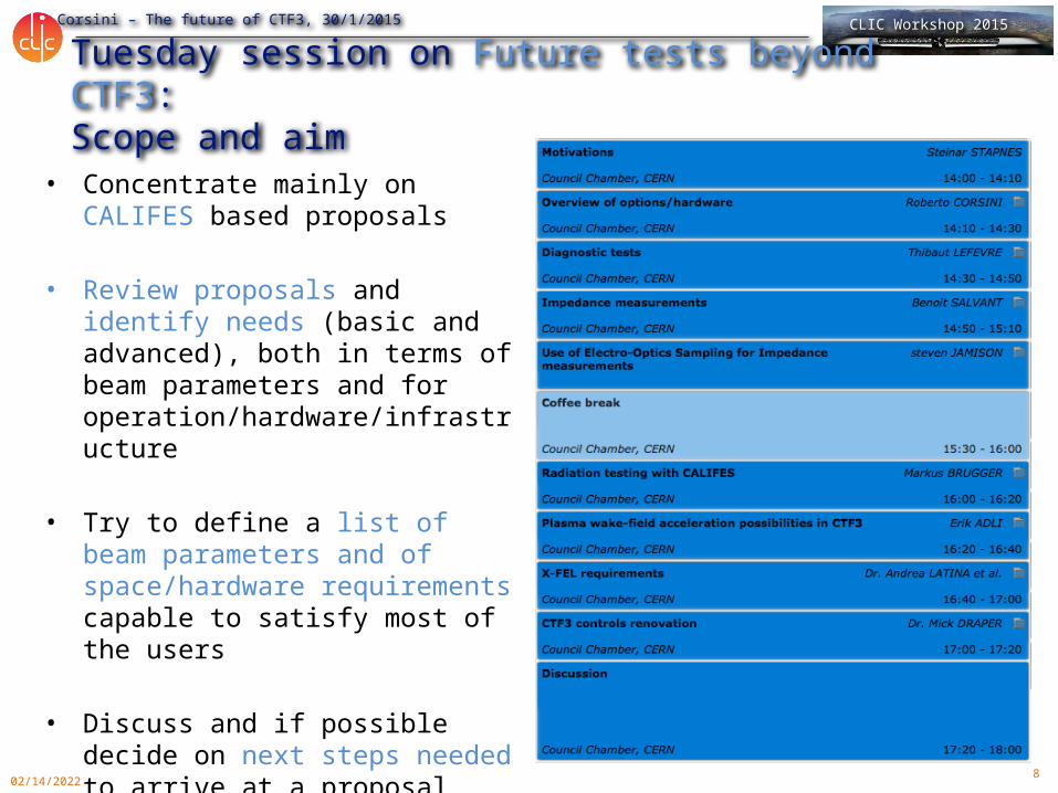
Tuesday session on Future tests beyond CTF3:Scope and aim
• Concentrate mainly on CALIFES based proposals
• Review proposals and identify needs (basic and advanced), both in terms of beam parameters and for operation/hardware/infrastructure
• Try to define a list of beam parameters and of space/hardware requirements capable to satisfy most of the users
• Discuss and if possible decide on next steps needed to arrive at a proposal
9
R. Corsini – The future of CTF3, 30/1/2015 CLIC Workshop 2015
05/01/2023
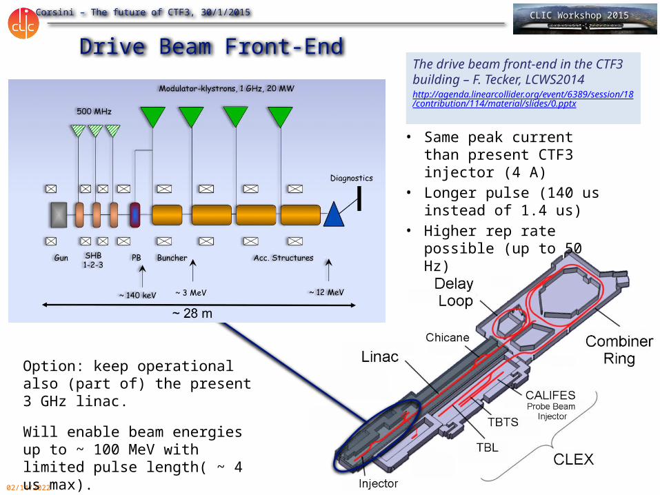
Drive Beam Front-End
• Same peak current than present CTF3 injector (4 A)
• Longer pulse (140 us instead of 1.4 us)
• Higher rep rate possible (up to 50 Hz)
Option: keep operational also (part of) the present 3 GHz linac.Will enable beam energies up to ~ 100 MeV with limited pulse length( ~ 4 us max).
The drive beam front-end in the CTF3 building – F. Tecker, LCWS2014http://agenda.linearcollider.org/event/6389/session/18/contribution/114/material/slides/0.pptx
10
R. Corsini – The future of CTF3, 30/1/2015 CLIC Workshop 2015
05/01/2023
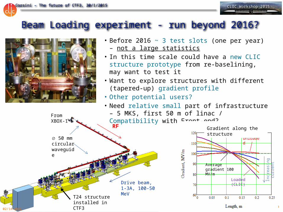
Beam Loading experiment - run beyond 2016?
Drive beam, 1-3A, 100-50 MeV
50 mm circular waveguide
RF
• Before 2016 ~ 3 test slots (one per year) – not a large statistics
• In this time scale could have a new CLIC structure prototype from re-baselining, may want to test it
• Want to explore structures with different (tapered-up) gradient profile
• Other potential users?• Need relative small part of infrastructure – 5 MKS,
first 50 m of linac / Compatibility with Front-end?
T24 structure installed in CTF3
From XBOX-1
CLEX
LINAC
DELAY LOOP
COMBINER RING
BL - BDR experiment
Unloaded
Loaded (CLIC)
Incr
easin
g cu
rren
t
Gradient along the structure
Average gradient 100 MV/m
11
R. Corsini – The future of CTF3, 30/1/2015 CLIC Workshop 2015
05/01/2023
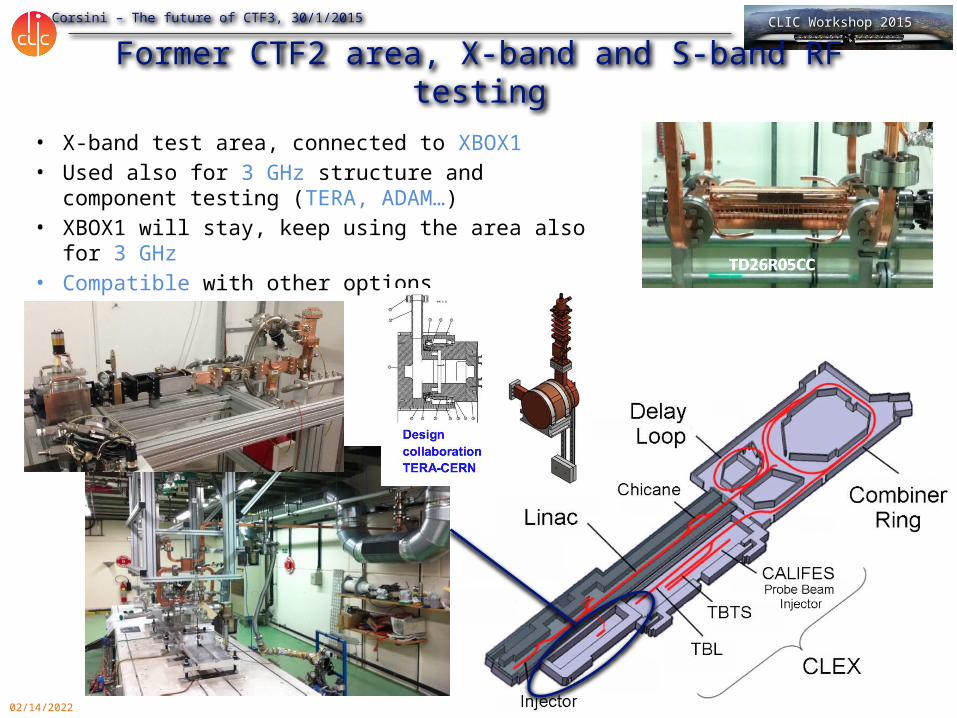
Former CTF2 area, X-band and S-band RF testing• X-band test area, connected to XBOX1• Used also for 3 GHz structure and component
testing (TERA, ADAM…)• XBOX1 will stay, keep using the area also for 3
GHz• Compatible with other options
12
R. Corsini – The future of CTF3, 30/1/2015 CLIC Workshop 2015
05/01/2023
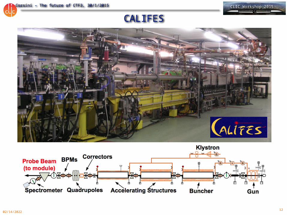
CALIFES
13
R. Corsini – The future of CTF3, 30/1/2015 CLIC Workshop 2015
05/01/2023
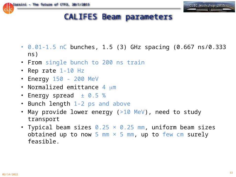
CALIFES Beam parameters
• 0.01-1.5 nC bunches, 1.5 (3) GHz spacing (0.667 ns/0.333 ns)• From single bunch to 200 ns train • Rep rate 1-10 Hz• Energy 150 - 200 MeV• Normalized emittance 4 mm• Energy spread ± 0.5 %• Bunch length 1-2 ps and above• May provide lower energy (>10 MeV), need to study transport• Typical beam sizes 0.25 × 0.25 mm, uniform beam sizes obtained
up to now 5 mm × 5 mm, up to few cm surely feasible.
14
R. Corsini – The future of CTF3, 30/1/2015 CLIC Workshop 2015
05/01/2023
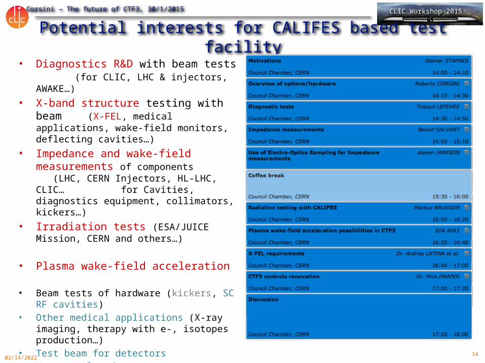
Potential interests for CALIFES based test facility• Diagnostics R&D with beam tests
(for CLIC, LHC & injectors, AWAKE…)• X-band structure testing with beam
(X-FEL, medical applications, wake-field monitors, deflecting cavities…)
• Impedance and wake-field measurements of components (LHC, CERN Injectors, HL-LHC, CLIC… for Cavities, diagnostics equipment, collimators, kickers…)
• Irradiation tests (ESA/JUICE Mission, CERN and others…)
• Plasma wake-field acceleration
• Beam tests of hardware (kickers, SC RF cavities)
• Other medical applications (X-ray imaging, therapy with e-, isotopes production…)
• Test beam for detectors• Vacuum related tests• …
15
R. Corsini – The future of CTF3, 30/1/2015 CLIC Workshop 2015
o Machine operation schedule @ CERNo Long periods without the capability of performing beam testso Limited beam time available for Machine Developments combined with a high
number of requests
o Hardware installation periods are limitedo Any further improvements/modifications can not be implemented quickly
o Testing at Independent Facility will faster the developments and ensure that we installed well-understood devices on operation machine
o Developing new concept versus Reliable operationo Operational machine have strict requirements in terms of vacuum-outgassing
performance/ bakeability not always compatible with R&D needso e.g. Testing gas ionization monitor and their performance as function of gas
pressure
T. Lefevre
CALIFES for diagnostics R&D - Why

16
R. Corsini – The future of CTF3, 30/1/2015 CLIC Workshop 2015
o CERN acceleratorso LHC, HL-LHC, LIU (SPS, PS, PSB) projectso CLIC/ILC, AWAKE, FCC studies
o Future Challenges in Beam Instrumentation
o Unprecedented request for precisiono Positioning down to below the micron level
o Treatment of increasingly more datao Bunch by bunch measurements for all parameters:: Test of state of the art
acquisition system (electric or optical domain)o Dealing with high beam powers
o Non-invasive measurement techniques (Gas profile monitor, Quadrupolar PU, ..)
o Robust and reliable machine protection and beam loss monitoring systems o Dealing with the (ultra) fast
o Sub-picosecond bunch lengths in AWAKE and CLIC o Longitudinal tomography in LHC (picosecond range)o Fast transverse beam position monitors (HL-LHC Crab cavities and
transverse beam Instability diagnostics)
What forT. Lefevre
17
R. Corsini – The future of CTF3, 30/1/2015 CLIC Workshop 2015
o A Test facility can not address all specific issues. But ….
o System performance under realistic conditions that are not easily achievable in laboratoryo Test with realistic signals state of the art electronic
o i.e. Response to short pulses with high signal amplitudeo Test of UV, optical, X-ray monitors where no other source can reproduce beam
induced radiationo Imaging technique and Beam halo monitoringo Use of electro-optical crystal
o Validation of particle detector design (e.g. Beam loss monitor/ Luminosity monitor)o Sensitivity checks, linearity (or non-linearity) checks, ..
o Study the behavior of devices with respect to beam position / bunch length / bunch intensity variations
What forT. Lefevre
18
R. Corsini – The future of CTF3, 30/1/2015 CLIC Workshop 2015
o Electron linac is the cheapest way to provide relativistic beamso Beam energy higher than 200MeV (3.5GeV max) – similar g as on SPS (LHC)
o Photo-injector provides a modular bunch spacingo Single bunch capabilityo Bunch spacing similar to CERN beams (1ns, 5ns, 25ns, 50ns, .. )o Pump – probe experiment (wake-field study, impedance measurement, ..)
o Simplicity, Reliability and Flexibility
o Wish list for Beam parameterso Good emittance to reach small beam size (<50um)o Short and long bunches (100fs up to 200ps)o Large range of bunch intensity o Possibility to study time to position correlation (Crabbing)
Slightly modified version of CALIFES
o Applications requiring high beam current would require Drive Beam Injector (Beam heating studies, ..)
How T. Lefevre
19
R. Corsini – The future of CTF3, 30/1/2015 CLIC Workshop 2015
05/01/2023
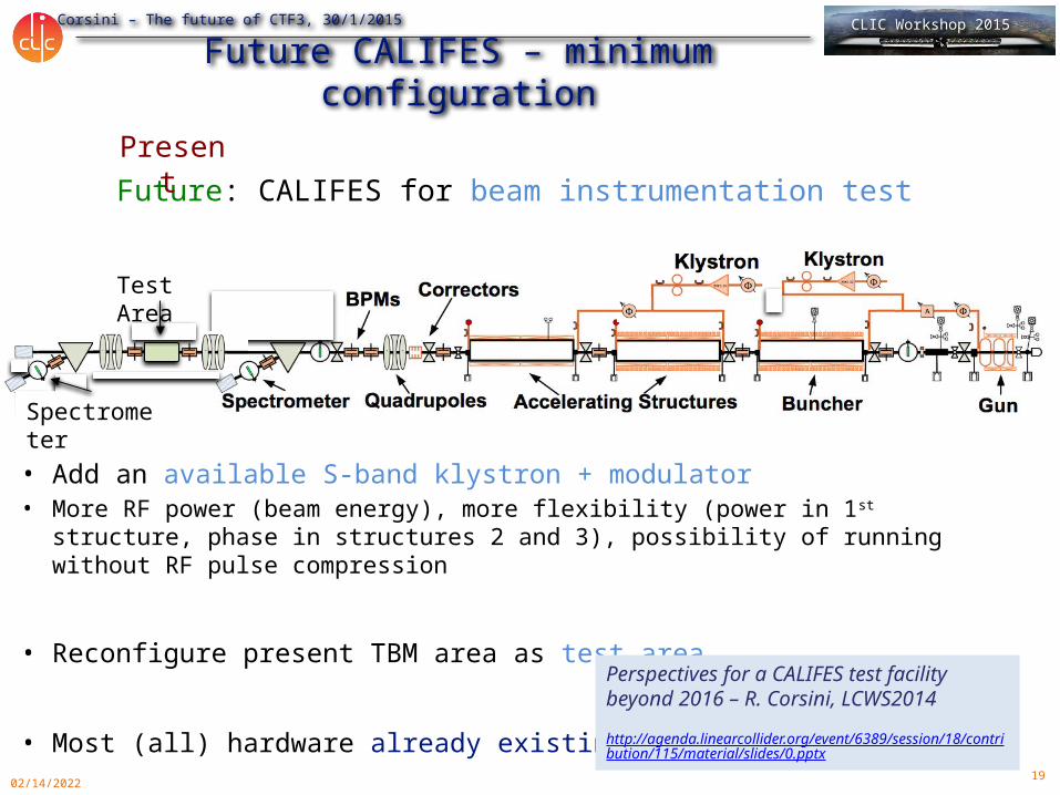
Future CALIFES – minimum configuration
• Add an available S-band klystron + modulator• More RF power (beam energy), more flexibility (power in 1st structure,
phase in structures 2 and 3), possibility of running without RF pulse compression
• Reconfigure present TBM area as test area
• Most (all) hardware already existing
Future: CALIFES for beam instrumentation test
Test Area
Spectrometer
Present
Perspectives for a CALIFES test facility beyond 2016 – R. Corsini, LCWS2014
http://agenda.linearcollider.org/event/6389/session/18/contribution/115/material/slides/0.pptx
20
R. Corsini – The future of CTF3, 30/1/2015 CLIC Workshop 2015
05/01/2023
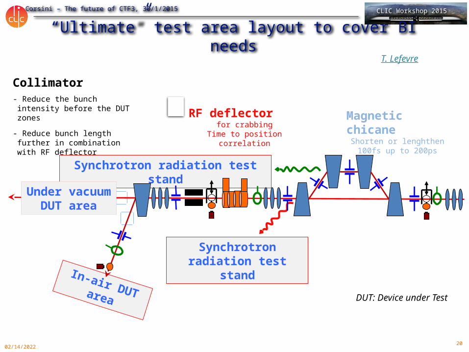
“Ultimate” test area layout to cover BI needs
Magnetic chicaneShorten or lenghthen
100fs up to 200ps
RF deflectorfor crabbing
Time to position correlation
- Reduce the bunch intensity before the DUT zones
- Reduce bunch length further in combination with RF deflector
Collimator
T. Lefevre
Synchrotron radiation test stand
In-air DUT area
Synchrotron radiation test stand
Under vacuum DUT area
DUT: Device under Test

21
R. Corsini – The future of CTF3, 30/1/2015 CLIC Workshop 2015
05/01/2023
Irradiation testing with CALIFESM. Brugger, R. Garcia Alia
22
R. Corsini – The future of CTF3, 30/1/2015 CLIC Workshop 2015
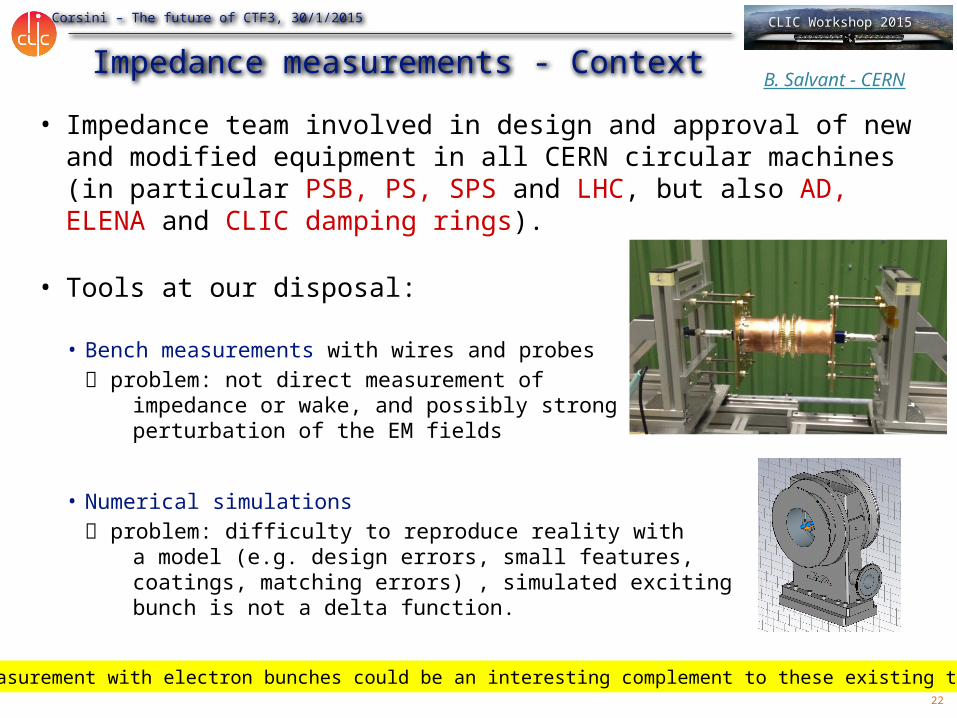
Impedance measurements - Context• Impedance team involved in design and approval of new and
modified equipment in all CERN circular machines (in particular PSB, PS, SPS and LHC, but also AD, ELENA and CLIC damping rings).
• Tools at our disposal:
• Bench measurements with wires and probes problem: not direct measurement of
impedance or wake, and possibly strong perturbation of the EM fields
• Numerical simulations problem: difficulty to reproduce reality with
a model (e.g. design errors, small features, coatings, matching errors) , simulated exciting bunch is not a delta function.
Measurement with electron bunches could be an interesting complement to these existing tools
B. Salvant - CERN
23
R. Corsini – The future of CTF3, 30/1/2015 CLIC Workshop 2015
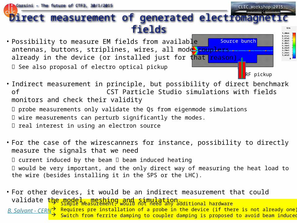
Simple measurement, would not need any additional hardware Requires pre installation of a probe in the device (if there is not already one). Switch from ferrite damping to coupler damping is proposed to avoid beam induced heating
Source bunch
RF pickup
Direct measurement of generated electromagnetic fields• Possibility to measure EM fields from available
antennas, buttons, striplines, wires, all mode couplers already in the device (or installed just for that reason). See also proposal of electro optical pickup
• Indirect measurement in principle, but possibility of direct benchmark of CST Particle Studio simulations with fields monitors and check their validity probe measurements only validate the Qs from eigenmode simulations wire measurements can perturb significantly the modes. real interest in using an electron source
• For the case of the wirescanners for instance, possibility to directly measure the signals that we need current induced by the beam beam induced heating would be very important, and the only direct way of measuring the heat load to the wire (besides installing it in the SPS or the LHC).
• For other devices, it would be an indirect measurement that could validate the model, meshing and simulation.
B. Salvant - CERN

24
R. Corsini – The future of CTF3, 30/1/2015 CLIC Workshop 2015
05/01/2023
Electro-optic Diagnostics for Wake-field CharacterisationS. JamisonASTeC - Daresbury National Lab
CALIFES EO Test
25
R. Corsini – The future of CTF3, 30/1/2015 CLIC Workshop 2015
05/01/2023
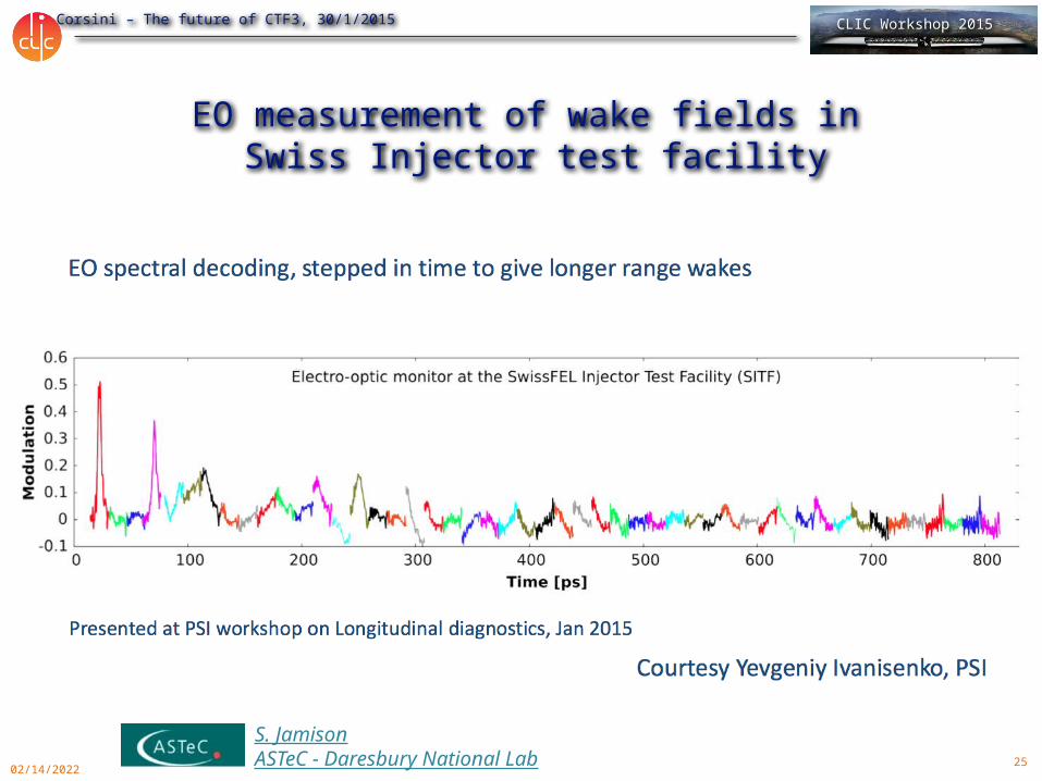
EO measurement of wake fields in Swiss Injector test facility
S. JamisonASTeC - Daresbury National Lab
26
R. Corsini – The future of CTF3, 30/1/2015 CLIC Workshop 2015
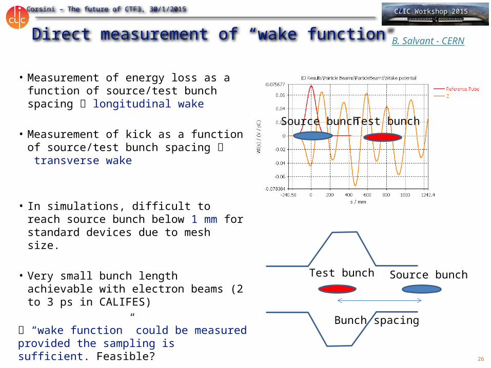
Direct measurement of “wake function”
• Measurement of energy loss as a function of source/test bunch spacing longitudinal wake
• Measurement of kick as a function of source/test bunch spacing transverse wake
• In simulations, difficult to reach source bunch below 1 mm for standard devices due to mesh size.
• Very small bunch length achievable with electron beams (2 to 3 ps in CALIFES)
“wake function” could be measured provided the sampling is sufficient. Feasible?
Test bunch Source bunch
Bunch spacing
Test bunchSource bunch
B. Salvant - CERN
27
R. Corsini – The future of CTF3, 30/1/2015 CLIC Workshop 2015
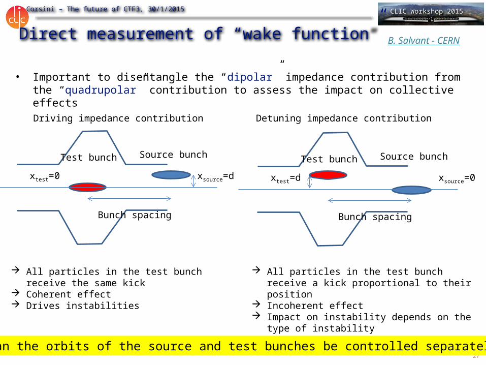
Direct measurement of “wake function”
• Important to disentangle the “dipolar” impedance contribution from the “quadrupolar” contribution to assess the impact on collective effects
Test bunch Source bunch
Bunch spacing
xsource=dxtest=0
Test bunch Source bunch
Bunch spacing
xsource=0xtest=d
Driving impedance contribution Detuning impedance contribution
All particles in the test bunch receive the same kick
Coherent effect Drives instabilities
All particles in the test bunch receive a kick proportional to their position
Incoherent effect Impact on instability depends on the type of
instability
Can the orbits of the source and test bunches be controlled separately?
B. Salvant - CERN
28
R. Corsini – The future of CTF3, 30/1/2015 CLIC Workshop 2015
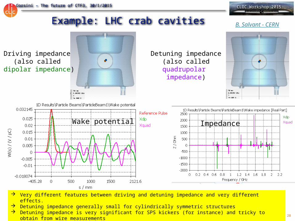
Example: LHC crab cavities
Driving impedance (also called
dipolar impedance)
Detuning impedance(also called quadrupolar
impedance)
Very different features between driving and detuning impedance and very different effects. Detuning impedance generally small for cylindrically symmetric structures Detuning impedance is very significant for SPS kickers (for instance) and tricky to obtain from wire measurements Need to control separately source and test bunches
Wake potential Impedance
B. Salvant - CERN

29
R. Corsini – The future of CTF3, 30/1/2015 CLIC Workshop 2015
Potential limitations- Minimum kick strength observable with the BPM resolution
Many components are in the 1 to 10 kOhm/m range for the transverse impedance, in the mOhm range for the longitudinal impedance
Previous studies show that the kick is of the order of 10 microns after 1 m for 10 kOhm/m Roberto Corsini proposed possibilities to amplify this kick using lever arms This could require 3 BPMs before the device and 3 BPMs after the device (H. Schmickler) Reducing the energy of the test bunch would help!
- Need to disentangle between the test and source bunch Can we resolve 0.1 ns between two bunches? Challenging together with resolution requirements Would need special BPM development Could a high bandwidth kicker be used (prototype installed in SPS to work in GHz range)?
- Accurate control of the orbit and spacing of test vs source difficult to do with one electron source, contrary to FACET ideas to delay the bunch, delay the laser pulse to control the spacing ideas to move the laser pulse transverse position to control independently the transverse position this could be the main limitation for the setup
- Control of intensity of both bunches (highest on source and low on test)
- Available length (for both device installation and for observation) some critical elements are very long (SPS septa, LHC TDI and kickers).
- Need for large flexibility in length and radius of input device the facility may become a tapering factory.
- Contribution from the BPMs and tapers should not dominate (from 40 mm/20 mm radius to the aperture of the element)
B. Salvant - CERN
30
R. Corsini – The future of CTF3, 30/1/2015 CLIC Workshop 2015
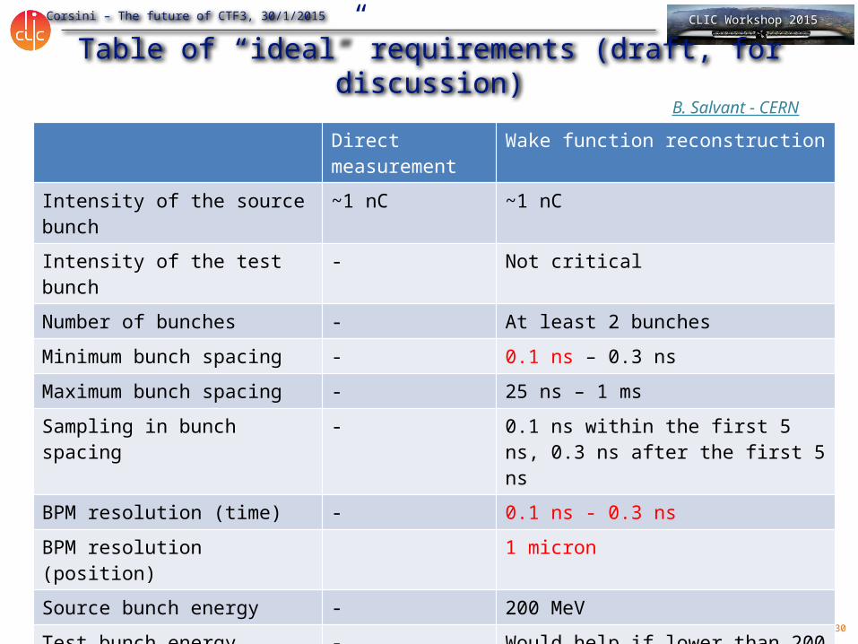
Table of “ideal” requirements (draft, for discussion)
Direct measurement
Wake function reconstruction
Intensity of the source bunch
~1 nC ~1 nC
Intensity of the test bunch - Not critical
Number of bunches - At least 2 bunches
Minimum bunch spacing - 0.1 ns – 0.3 ns
Maximum bunch spacing - 25 ns – 1 ms
Sampling in bunch spacing - 0.1 ns within the first 5 ns, 0.3 ns after the first 5 ns
BPM resolution (time) - 0.1 ns - 0.3 ns
BPM resolution (position) 1 micron
Source bunch energy - 200 MeV
Test bunch energy - Would help if lower than 200 MeV
Available installation length 1.5 m for devices + 1 m for taper = at least 2.5 m
At least 2.5 m
B. Salvant - CERN
31
R. Corsini – The future of CTF3, 30/1/2015 CLIC Workshop 2015
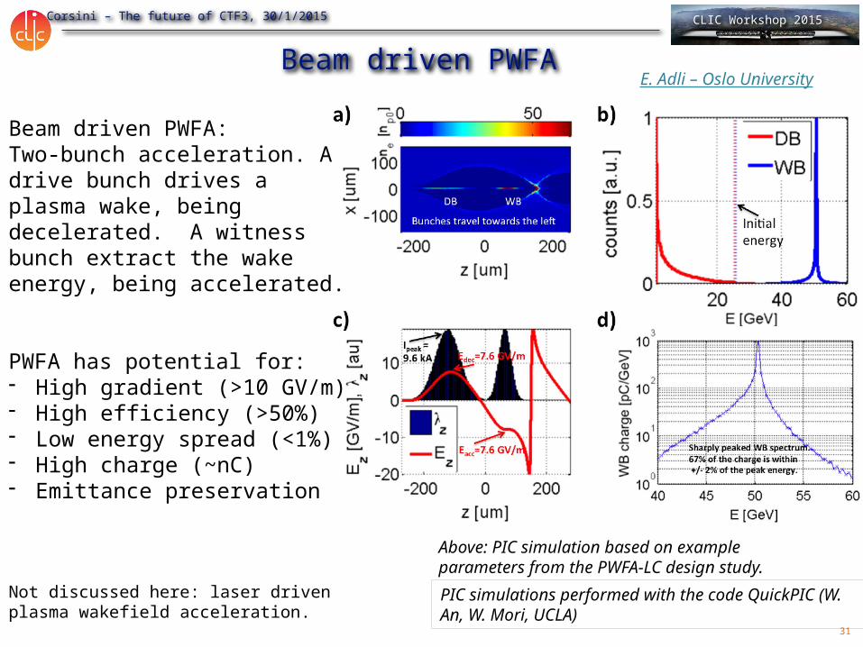
Beam driven PWFA
Beam driven PWFA:Two-bunch acceleration. A drive bunch drives a plasma wake, being decelerated. A witness bunch extract the wake energy, being accelerated.
PWFA has potential for:- High gradient (>10 GV/m)- High efficiency (>50%)- Low energy spread (<1%)- High charge (~nC)- Emittance preservation
Above: PIC simulation based on example parameters from the PWFA-LC design study.
Not discussed here: laser driven plasma wakefield acceleration.
PIC simulations performed with the code QuickPIC (W. An, W. Mori, UCLA)
E. Adli – Oslo University
32
R. Corsini – The future of CTF3, 30/1/2015 CLIC Workshop 2015
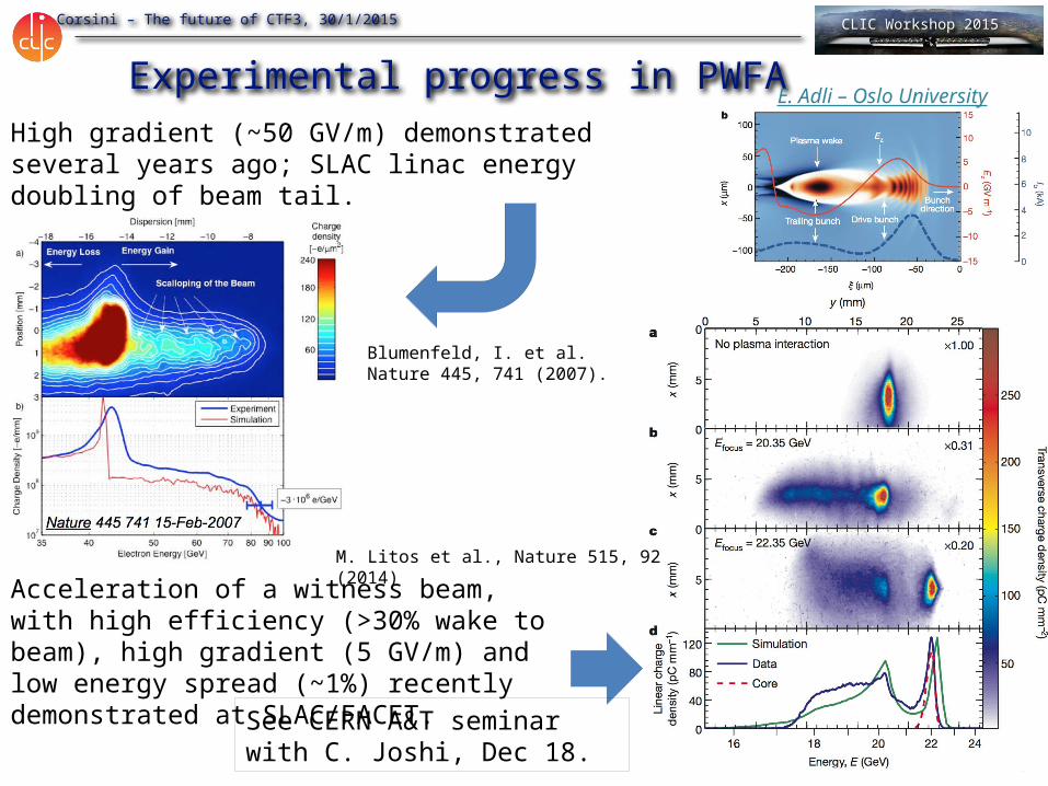
Experimental progress in PWFAHigh gradient (~50 GV/m) demonstrated several years ago; SLAC linac energy doubling of beam tail.
Acceleration of a witness beam, with high efficiency (>30% wake to beam), high gradient (5 GV/m) and low energy spread (~1%) recently demonstrated at SLAC/FACET.
M. Litos et al., Nature 515, 92 (2014)
Blumenfeld, I. et al. Nature 445, 741 (2007).
See CERN A&T seminar with C. Joshi, Dec 18.
E. Adli – Oslo University
33
R. Corsini – The future of CTF3, 30/1/2015 CLIC Workshop 2015
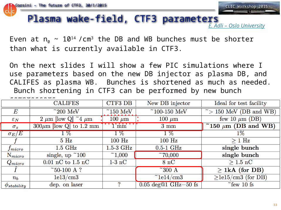
Plasma wake-field, CTF3 parametersEven at n0 ~ 1014 /cm3 the DB and WB bunches must be shorter than what is currently available in CTF3.
On the next slides I will show a few PIC simulations where I use parameters based on the new DB injector as plasma DB, and CALIFES as plasma WB. Bunches is shortened as much as needed. Bunch shortening in CTF3 can be performed by new bunch compressors.
E. Adli – Oslo University
34
R. Corsini – The future of CTF3, 30/1/2015 CLIC Workshop 2015
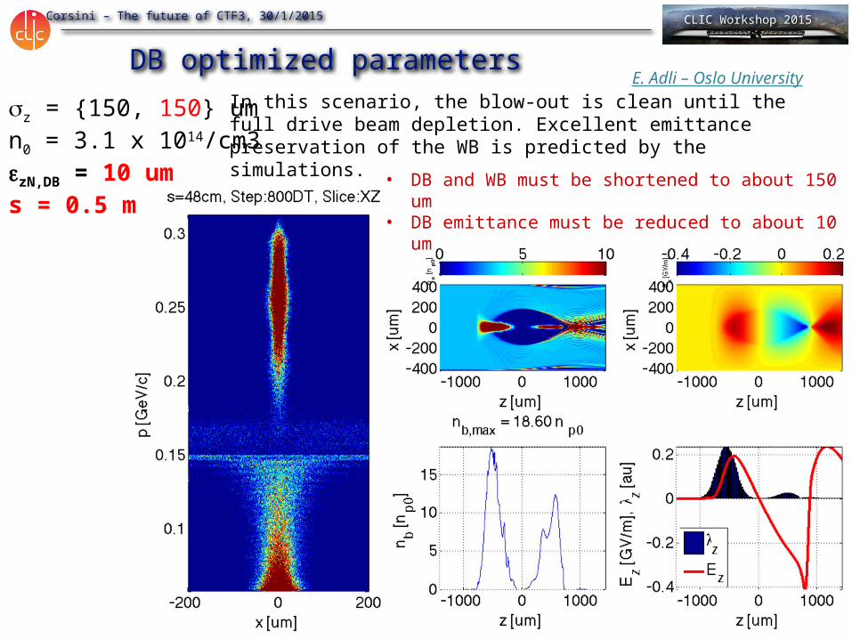
sz = {150, 150} umn0 = 3.1 x 10¹⁴/cm3ezN,DB = 10 ums = 0.5 m
DB optimized parametersIn this scenario, the blow-out is clean until the full drive beam depletion. Excellent emittance preservation of the WB is predicted by the simulations.
• DB and WB must be shortened to about 150 um• DB emittance must be reduced to about 10 um
E. Adli – Oslo University
35
R. Corsini – The future of CTF3, 30/1/2015 CLIC Workshop 2015
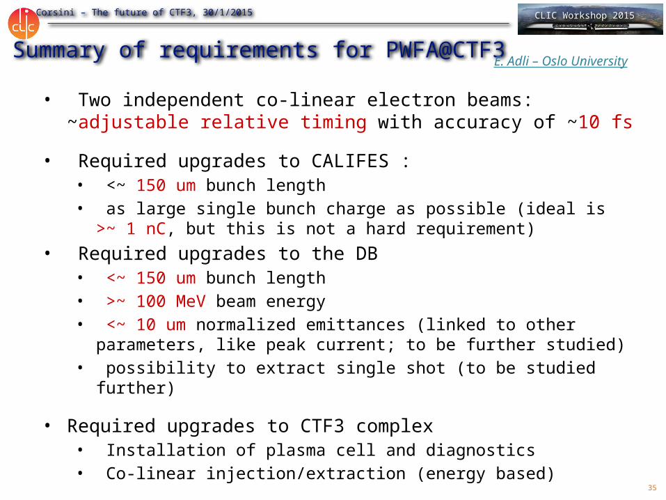
Summary of requirements for PWFA@CTF3
• Two independent co-linear electron beams: ~adjustable relative timing with accuracy of ~10 fs
• Required upgrades to CALIFES : • <~ 150 um bunch length• as large single bunch charge as possible (ideal is >~ 1 nC, but
this is not a hard requirement)• Required upgrades to the DB
• <~ 150 um bunch length• >~ 100 MeV beam energy• <~ 10 um normalized emittances (linked to other parameters,
like peak current; to be further studied)• possibility to extract single shot (to be studied further)
• Required upgrades to CTF3 complex• Installation of plasma cell and diagnostics• Co-linear injection/extraction (energy based)
E. Adli – Oslo University
36
R. Corsini – The future of CTF3, 30/1/2015 CLIC Workshop 2015
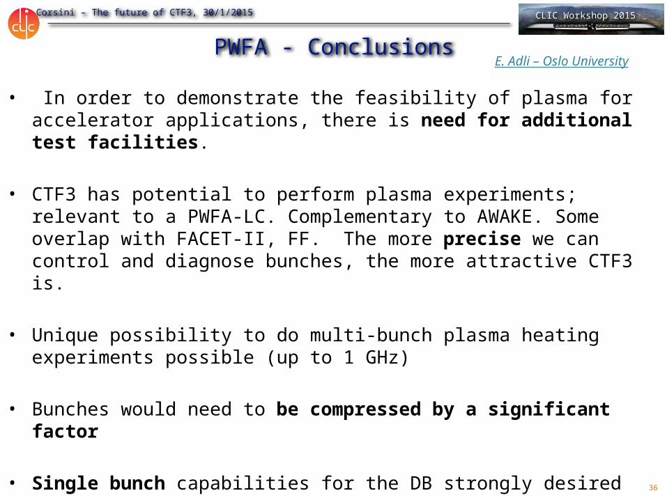
PWFA - Conclusions
• In order to demonstrate the feasibility of plasma for accelerator applications, there is need for additional test facilities.
• CTF3 has potential to perform plasma experiments; relevant to a PWFA-LC. Complementary to AWAKE. Some overlap with FACET-II, FF. The more precise we can control and diagnose bunches, the more attractive CTF3 is.
• Unique possibility to do multi-bunch plasma heating experiments possible (up to 1 GHz)
• Bunches would need to be compressed by a significant factor
• Single bunch capabilities for the DB strongly desired
• We are interested in further developing this proposal with CLIC/CTF3
E. Adli – Oslo University
37
R. Corsini – The future of CTF3, 30/1/2015 CLIC Workshop 2015
05/01/2023
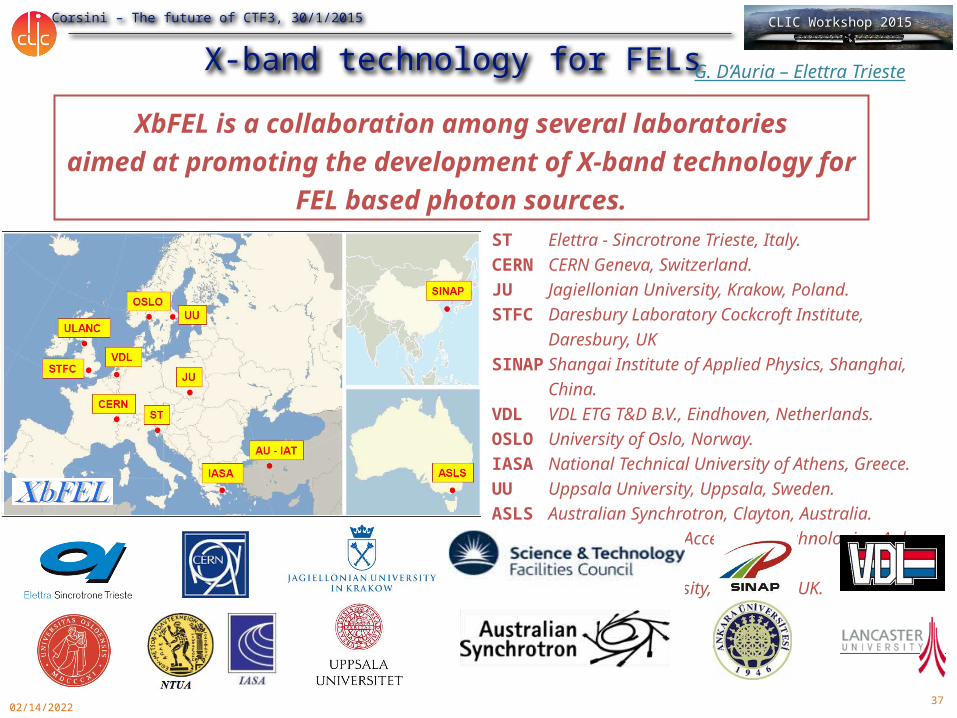
X-band technology for FELs
ST Elettra - Sincrotrone Trieste, Italy.CERN CERN Geneva, Switzerland.JU Jagiellonian University, Krakow, Poland.STFC Daresbury Laboratory Cockcroft Institute, Daresbury, UKSINAP Shangai Institute of Applied Physics, Shanghai, China.VDL VDL ETG T&D B.V., Eindhoven, Netherlands.OSLO University of Oslo, Norway.IASA National Technical University of Athens, Greece.UU Uppsala University, Uppsala, Sweden.ASLS Australian Synchrotron, Clayton, Australia.UA-IAT Institute of Accelerator Technologies, Ankara, Turkey.ULANC Lancaster University, Lancaster, UK.
XbFEL is a collaboration among several laboratoriesaimed at promoting the development of X-band technology for FEL
based photon sources.
G. D’Auria – Elettra Trieste
38
R. Corsini – The future of CTF3, 30/1/2015 CLIC Workshop 2015
Potential tests for an X-band FEL using the CALIFES beam
05/01/2023
New hardware required Hardware already availableA. Latina (CERN) with relevant inputs from G. D’Auria, S. Di Mitri (ELETTRA), M. Pedrozzi (PSI), A. Dexter and G. Burt (Cockcroft, Lancaster)
39
R. Corsini – The future of CTF3, 30/1/2015 CLIC Workshop 2015
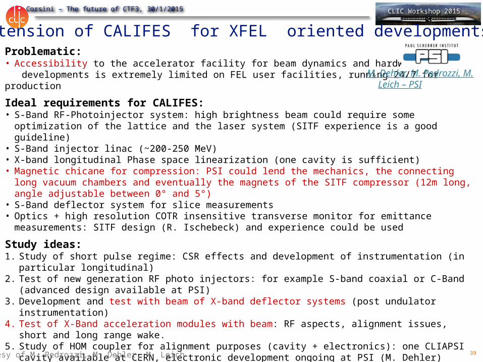
Extension of CALIFES for XFEL oriented developments.Problematic:• Accessibility to the accelerator facility for beam dynamics and hardware developments is extremely limited on FEL user facilities, running 24/7 for production
Ideal requirements for CALIFES:• S-Band RF-Photoinjector system: high brightness beam could require some optimization of the lattice and the
laser system (SITF experience is a good guideline)• S-Band injector linac (~200-250 MeV)• X-band longitudinal Phase space linearization (one cavity is sufficient)• Magnetic chicane for compression: PSI could lend the mechanics, the connecting long vacuum chambers and
eventually the magnets of the SITF compressor (12m long, angle adjustable between 0° and 5°)• S-Band deflector system for slice measurements• Optics + high resolution COTR insensitive transverse monitor for emittance measurements: SITF design (R.
Ischebeck) and experience could be used
Study ideas:1. Study of short pulse regime: CSR effects and development of instrumentation (in particular longitudinal)2. Test of new generation RF photo injectors: for example S-band coaxial or C-Band (advanced design available
at PSI)3. Development and test with beam of X-band deflector systems (post undulator instrumentation)4. Test of X-Band acceleration modules with beam: RF aspects, alignment issues, short and long range wake.5. Study of HOM coupler for alignment purposes (cavity + electronics): one CLIAPSI cavity available at CERN,
electronic development ongoing at PSI (M. Dehler)
If enough space available • Demonstration of non-linear magnetic compression with negative R56 and adjustable T566. Preliminary
design study available at PSI (A. Streun). Required ~30 m and multipole magnets. Complex but: X-band linearization not required, one important source of jitter removed increases of compression stability.
Courtesy of M. Pedrozzi, M. Dehler, M. Leich
M. Dehler, M. Pedrozzi, M. Leich – PSI
40
R. Corsini – The future of CTF3, 30/1/2015 CLIC Workshop 2015
Advanced Beam Physics
• Compare the performances of a purely-magnetic compression scheme, w.r.t. one including velocity bunching, both in terms of macroscopic properties of the beam as well as in terms of micro-bunching
• Micro-bunching gain measurements and comparison with analytical models
• Electron beam shot-noise bunching suppression + lasing (some undulators would be needed)
• Tests of Double-Bend Achromat (DBA) with CSR suppression
• Electron comb generation using masks in a dispersive region, and transport control
• Tests of bunch compression with sextupoles in the dispersive region (verify the impact on the longitudinal phase space)
• Measurement of emittance scaling with the photo-injector charge (models predict a shift from power of ½ to 1/3 but needs more accurate studies)
S. Di Mitri – Elettra Trieste

41
R. Corsini – The future of CTF3, 30/1/2015 CLIC Workshop 2015
Shaping ability of MasksMultiple masks used to study bunch shaping
PARMELA Simulation results
x [mm]-12 -8 -4 0 4 8 12
y [m
m]
-12
-8
-4
0
4
8
12
x [mm]-12 -8 -4 0 4 8 12
y [m
m]
-12
-8
-4
0
4
8
12
x [mm]-12 -8 -4 0 4 8 12
y [m
m]
-12
-8
-4
0
4
8
12
x [mm]-12 -8 -4 0 4 8 12
y [m
m]
-12
-8
-4
0
4
8
12
x [mm]-12 -8 -4 0 4 8 12
y [m
m]
-12
-8
-4
0
4
8
12
Normalized longitudinal position-0.4 -0.2 0.0 0.2 0.4 0.6 0.8 1.0
Arb
.
Longitudinal position [mm]-1.5 -1.0 -0.5 0.0 0.5 1.0 1.5 2.0 2.5
Arb
.
Longitudinal position [mm]-3 -2 -1 0 1 2 3
Arb
.
Horizontal profile after the maskFinal current profile
x [mm]-12 -8 -4 0 4 8 12
y [m
m]
-12
-8
-4
0
4
8
12
Before Mask
Apply
Mask
W. Gai – Argonne
42
R. Corsini – The future of CTF3, 30/1/2015 CLIC Workshop 2015
05/01/2023
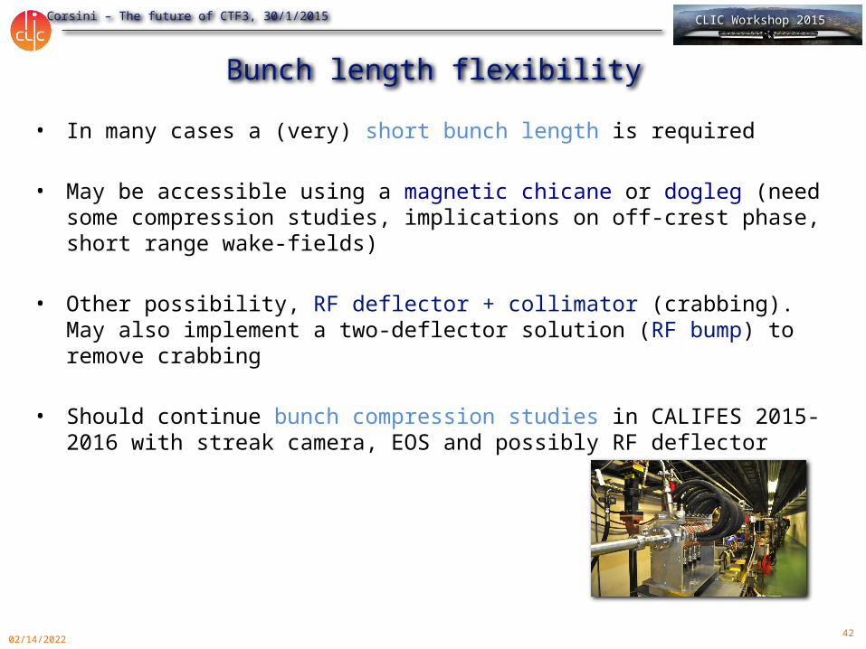
Bunch length flexibility• In many cases a (very) short bunch length is required
• May be accessible using a magnetic chicane or dogleg (need some compression studies, implications on off-crest phase, short range wake-fields)
• Other possibility, RF deflector + collimator (crabbing). May also implement a two-deflector solution (RF bump) to remove crabbing
• Should continue bunch compression studies in CALIFES 2015-2016 with streak camera, EOS and possibly RF deflector

43
R. Corsini – The future of CTF3, 30/1/2015 CLIC Workshop 2015
05/01/2023
Other flexibility requirements• Flexibility for single bunch / multibunch operation
• Flexibility in bunch charge – if high charge is needed, a switch between CALIFES gun and PHIN is still possible?
• Need of double pulse (drive + probe) for impedance/wake-fields measurements (and possibly plasma applications?). Flexibility in drive/probe bunch distance and independent control of transverse position/bunch charge may be critical aspects.

44
R. Corsini – The future of CTF3, 30/1/2015 CLIC Workshop 2015
05/01/2023
Conclusions• CTF3 in its present configuration will complete its program by end
2016 and stop operation• There is a strong interest by the CLIC collaboration in keep using
some of its hardware and infrastructure beyond 2016• Drive beam front-end• Dogleg beam loading experiment• RF testing (Xbox1, S band)• CALIFES for equipment testing
• In particular CALIFES may be a reasonably cheap multi-purpose test facility
• Useful within the CLIC study – potentially much wider interest• Clear synergies with other projects/labs may help in gathering
resources and support• CALIFES will be extremely useful already in its present form, but staged
upgrades will enhance flexibility/usefulness
• Will develop an integrated proposal including cost/resource assessment and evaluation of scientific case of the different options
45
R. Corsini – The future of CTF3, 30/1/2015 CLIC Workshop 2015
05/01/2023
THANKSfor your attention
46
R. Corsini – The future of CTF3, 30/1/2015 CLIC Workshop 2015
05/01/2023
Summary of (some) possible upgrades• Keep CALIFES for beam instrumentation test
• Add an available S-band klystron, modify waveguides• Add a chicane, another dedicated klystron for deflector• Change the deflector to a CR one• Closed RF bump + collimator for bunch length control• (Switch for the PHIN gun for higher charge)
• (Push the beam line toward the X-Box1 in CTF2)• Or transport the 12 GHz power to CLEX
• Add a 12 GHz crab cavity for bunch length diagnostic• (Add an undulator, a Compton scattering experiment…)
• Produce special beams for Impedance/Wakefield studies• 2 bunches of different energies with adjustable delay• Single bunch, short range wakes
47
R. Corsini – The future of CTF3, 30/1/2015 CLIC Workshop 2015
05/01/2023
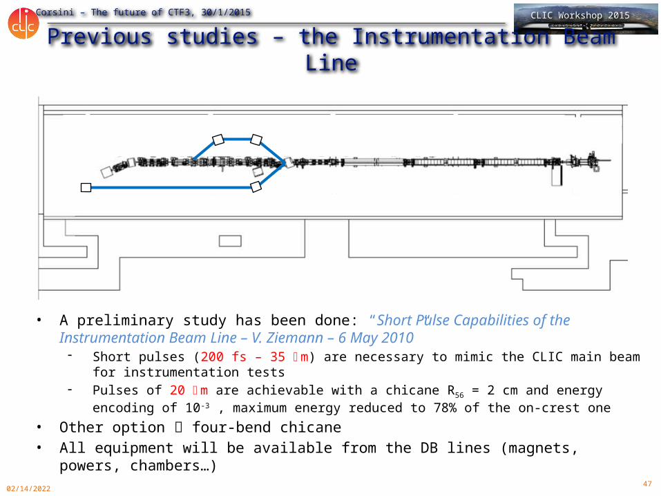
Previous studies – the Instrumentation Beam Line
• A preliminary study has been done: “Short Pulse Capabilities of the Instrumentation Beam Line – V. Ziemann – 6 May 2010” - Short pulses (200 fs – 35 mm) are necessary to mimic the CLIC main beam for
instrumentation tests- Pulses of 20 mm are achievable with a chicane R56 = 2 cm and energy encoding of 10-
3 , maximum energy reduced to 78% of the on-crest one• Other option four-bend chicane• All equipment will be available from the DB lines (magnets, powers,
chambers…)
48
R. Corsini – The future of CTF3, 30/1/2015 CLIC Workshop 2015
05/01/2023
Some consideration on resources
• Given the present CTF3 material budget/manpower, one may roughly evaluate the resources needed to keep CALIFES running after 2016 to about:
• 200-300 kCHF/year (including M to P – students and PJAS)• About 5 FTEs (staff and fellows)
• The above would include a minimum upgrade (1 ½ additional klystron, rearrangement of test area)
• Must do a more precise evaluation for the more ambitious upgrade options
49
R. Corsini – The future of CTF3, 30/1/2015 CLIC Workshop 2015
05/01/2023
Beam parameters• CTF3 Drive beam (present)
• 4 A, 1 us pulses (trains of 1-3 nC bunches, 1.5/3 GHz spacing)• rep rate 1-50 Hz• 50 – 125 MeV• May provide lower energy (>10 MeV), need to study transport• Typical beam sizes 1 × 1 mm, may easily fill round chamber, 4 cm
diameter.
• CTF3 Drive beam (new Front-End)• 4 A, up to 140 us pulses (trains of 1-6 nC bunches, 0.5/1 GHz
spacing)• rep rate 1-50 Hz• 10 – 100 MeV• Typical beam sizes 1 × 1 mm, may easily fill round chamber, 4 cm
diameter.
50
R. Corsini – The future of CTF3, 30/1/2015 CLIC Workshop 2015
05/01/2023
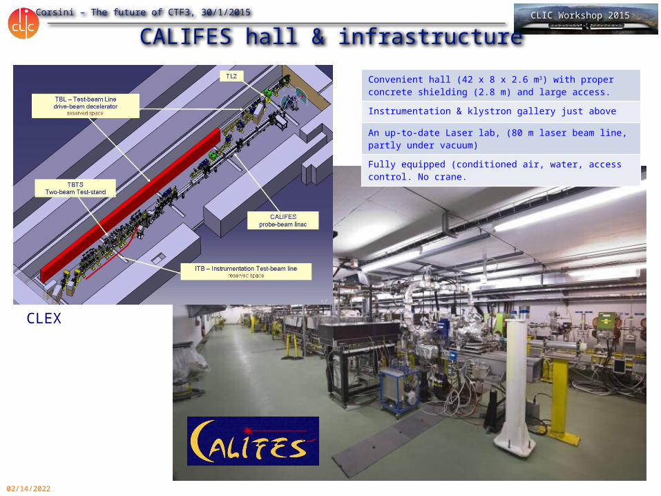
CALIFES hall & infrastructureConvenient hall (42 x 8 x 2.6 m3) with proper concrete shielding (2.8 m) and large access.Instrumentation & klystron gallery just above
An up-to-date Laser lab, (80 m laser beam line, partly under vacuum)Fully equipped (conditioned air, water, access control. No crane.
CLEX
51
R. Corsini – The future of CTF3, 30/1/2015 CLIC Workshop 2015
05/01/2023
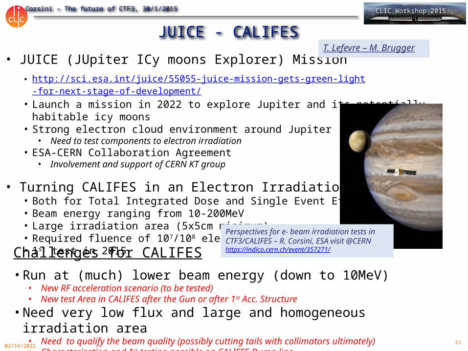
• JUICE (JUpiter ICy moons Explorer) Mission• http://sci.esa.int/juice/55055-juice-mission-gets-green-light-for-next-stage-of-development/• Launch a mission in 2022 to explore Jupiter and its potentially habitable icy moons• Strong electron cloud environment around Jupiter
• Need to test components to electron irradiation• ESA-CERN Collaboration Agreement
• Involvement and support of CERN KT group
• Turning CALIFES in an Electron Irradiation facility• Both for Total Integrated Dose and Single Event Effect• Beam energy ranging from 10-200MeV• Large irradiation area (5x5cm minimum)• Required fluence of 107/108 electron/cm2
• 1st test in 2015
Challenges for CALIFES• Run at (much) lower beam energy (down to 10MeV)
• New RF acceleration scenario (to be tested)• New test Area in CALIFES after the Gun or after 1st Acc. Structure
• Need very low flux and large and homogeneous irradiation area• Need to qualify the beam quality (possibly cutting tails with collimators ultimately)• Characterization and 1st testing possible on CALIFES Dump line
JUICE - CALIFES
Perspectives for e- beam irradiation tests in CTF3/CALIFES – R. Corsini, ESA visit @CERN https://indico.cern.ch/event/357271/
T. Lefevre – M. Brugger
52
R. Corsini – The future of CTF3, 30/1/2015 CLIC Workshop 2015
05/01/2023
Open issues/questions• Verify needed fluxes (test pieces, needed area…)
• Energy range – how critical? Verify low energy capabilities in CALIFES.
• How uniform should be the beam?
• What about the time structure (average vs. peak flux)?
• Total dose needed, testing time, running scenario…
• Layout of irradiation region – activation of collimator, air activation, dump…
• Timescale (before and/or after 2016)
• …
53
R. Corsini – The future of CTF3, 30/1/2015 CLIC Workshop 2015
05/01/2023
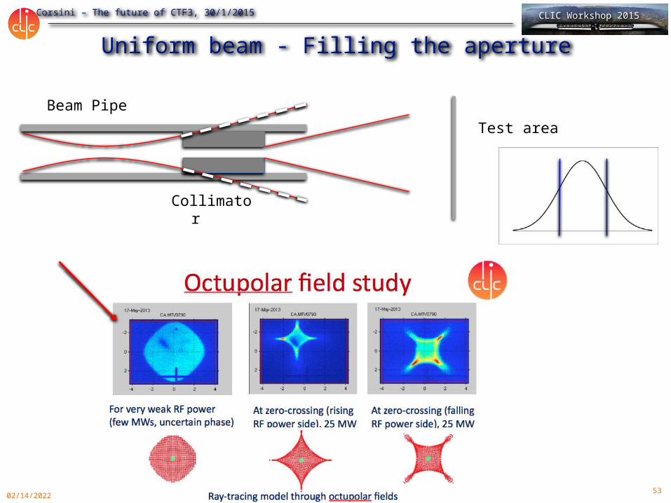
Uniform beam - Filling the aperture
Collimator
Test areaBeam Pipe
54
R. Corsini – The future of CTF3, 30/1/2015 CLIC Workshop 2015
05/01/2023
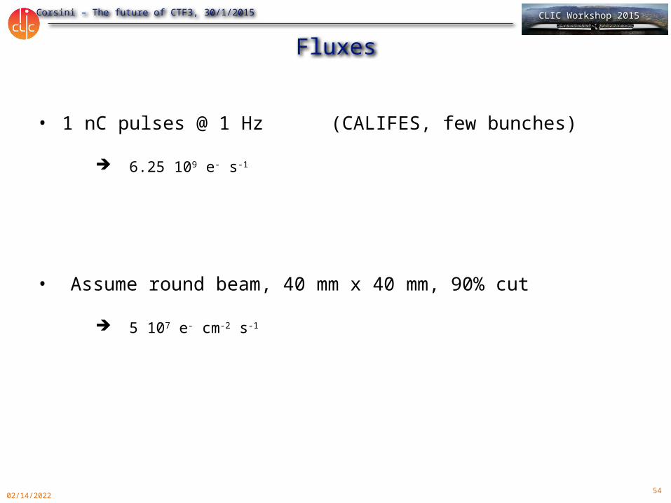
Fluxes
• 1 nC pulses @ 1 Hz (CALIFES, few bunches)
6.25 109 e- s-1
• Assume round beam, 40 mm x 40 mm, 90% cut
5 107 e- cm-2 s-1
55
R. Corsini – The future of CTF3, 30/1/2015 CLIC Workshop 2015
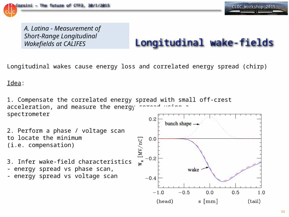
Longitudinal wake-fields
Longitudinal wakes cause energy loss and correlated energy spread (chirp)
Idea:
1. Compensate the correlated energy spread with small off-crest acceleration, and measure the energy spread using aspectrometer
2. Perform a phase / voltage scanto locate the minimum(i.e. compensation)
3. Infer wake-field characteristics from - energy spread vs phase scan,- energy spread vs voltage scan
A. Latina - Measurement of Short-Range LongitudinalWakefields at CALIFES

56
R. Corsini – The future of CTF3, 30/1/2015 CLIC Workshop 2015
Setup, parameters, and simulation of phase scan
CALIFES-like parameters:• Two CLIC AS with a/λ = 0.11• Bunch charge = 1 nC• Average energy = 200 MeV
Two bunch configurations considered:• Bunch uncorrelated espread = 0.25 %• Bunch length = 1200 umand:• Bunch uncorrelated espread = 0.5 %• Bunch length = 600 um
Four different longitudinal distributions• Gaussian• Uniform• Forward• Backward
The plots show the result energy spread:

57
R. Corsini – The future of CTF3, 30/1/2015 CLIC Workshop 2015
Dependence on voltage is much weaker
Example: 1.2 mm bunch length, 0.2% energy spread, two distributions
Gaussian:- Resolution required ~ 1 keV
UniformResolution required ~5 keV
58
R. Corsini – The future of CTF3, 30/1/2015 CLIC Workshop 2015
05/01/2023
59
R. Corsini – The future of CTF3, 30/1/2015 CLIC Workshop 2015
05/01/2023
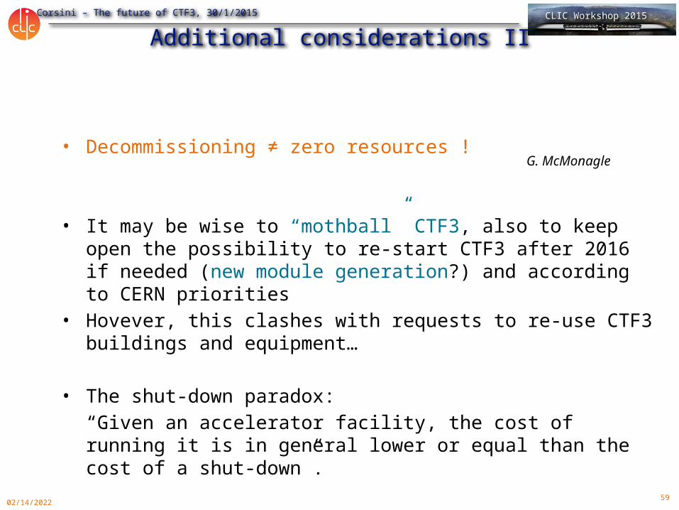
Additional considerations II
• Decommissioning ≠ zero resources !
• It may be wise to “mothball” CTF3, also to keep open the possibility to re-start CTF3 after 2016 if needed (new module generation?) and according to CERN priorities
• Hovever, this clashes with requests to re-use CTF3 buildings and equipment…
• The shut-down paradox:“Given an accelerator facility, the cost of running it is in general lower or equal than the cost of a shut-down”.
G. McMonagle
60
R. Corsini – The future of CTF3, 30/1/2015 CLIC Workshop 2015
05/01/2023
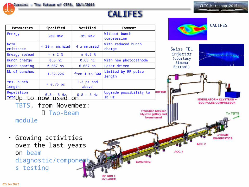
CALIFESParameters Specified Verified Comment
Energy 200 MeV 205 MeV Without bunch compressionNorm. emittance < 20 p mm.mrad 4 p mm.mrad With reduced bunch chargeEnergy spread < ± 2 % ± 0.5 %Bunch charge 0.6 nC 0.65 nC With new photocathodeBunch spacing 0.667 ns 0.667 ns Laser drivenNb of bunches 1-32-226 from 1 to 300 Limited by RF pulse lengthrms. bunch length < 0.75 ps 1-2 ps and
aboveRepetition rate 0.8 – 5 Hz 0.8 – 5 Hz Upgrade possibility to 10 Hz
• Up to now used on TBTS, from November: Two-Beam module
• Growing activities over the last years on beam diagnostic/components testing
CALIFES
Swiss FEL injector (courtesy
Simona Bettoni)
61
R. Corsini – The future of CTF3, 30/1/2015 CLIC Workshop 2015
05/01/2023
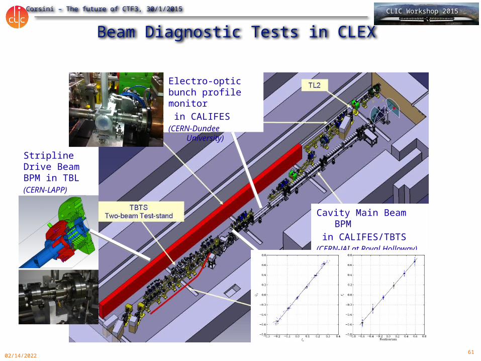
Beam Diagnostic Tests in CLEX
Stripline Drive Beam BPM in TBL (CERN-LAPP)
Electro-optic bunch profile monitor in CALIFES(CERN-Dundee University)
Cavity Main Beam BPM in CALIFES/TBTS (CERN-JAI at Royal Holloway)
62
R. Corsini – The future of CTF3, 30/1/2015 CLIC Workshop 2015
05/01/2023
X-band
• CALIFES may provide an unique opportunity to test X-band structures/modules with beam
• XBOX1 located very close (distance comparable to present low-loss line for dog-leg beam loading experiment)
• Straight-forward solution: connect to XBOX1 for beam testing in CLEX
• An upgraded CALIFES beam may be not too far from what is needed for FELs: “Playing ground” for X-band FEL beam studies and developments
• Future possibility: test a full X-band module (for X-band FEL or klystron-based CLIC) – may need an additional modulator/klystron
• Add more? …
63
R. Corsini – The future of CTF3, 30/1/2015 CLIC Workshop 2015
05/01/2023
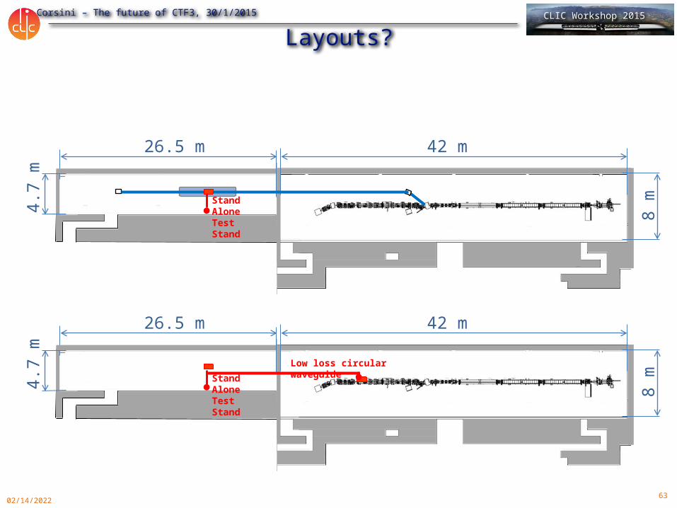
Layouts?4.
7 m
26.5 m 42 m
8 mStand
Alone Test Stand
4.7
m
26.5 m 42 m
8 mStand
Alone Test Stand
Low loss circular waveguide
64
R. Corsini – The future of CTF3, 30/1/2015 CLIC Workshop 2015
05/01/2023
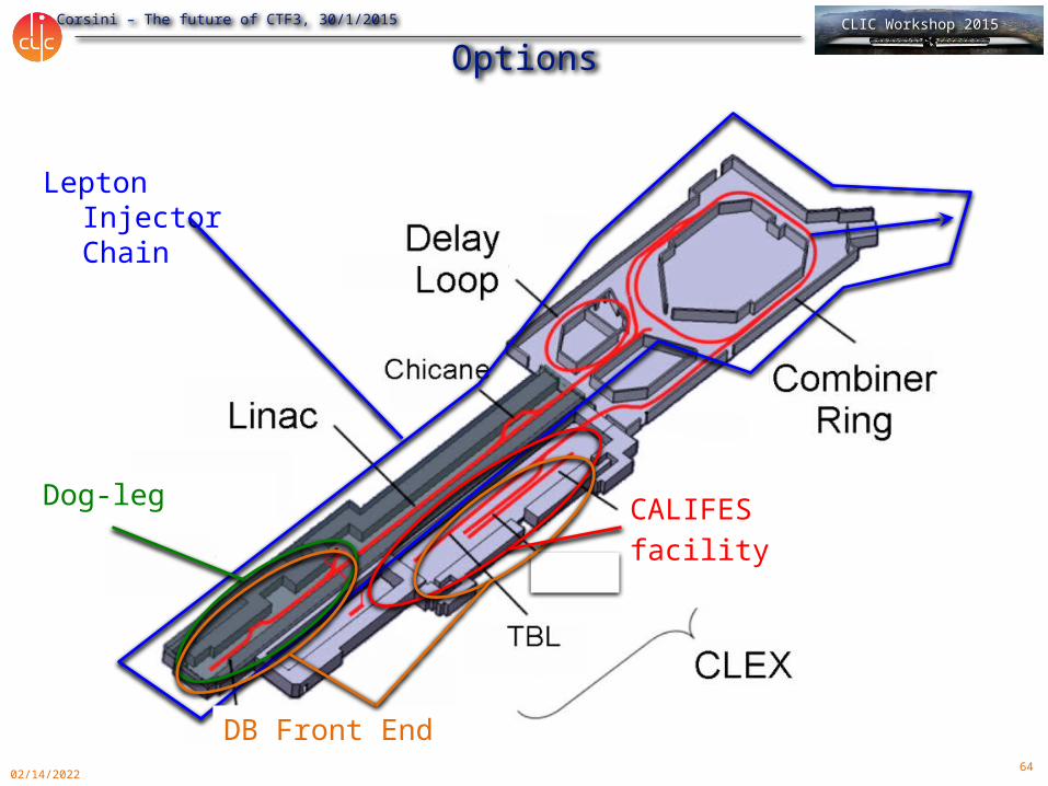
Options
Lepton Injector Chain
CALIFES facility
DB Front End
Dog-leg
65
R. Corsini – The future of CTF3, 30/1/2015 CLIC Workshop 2015
05/01/2023
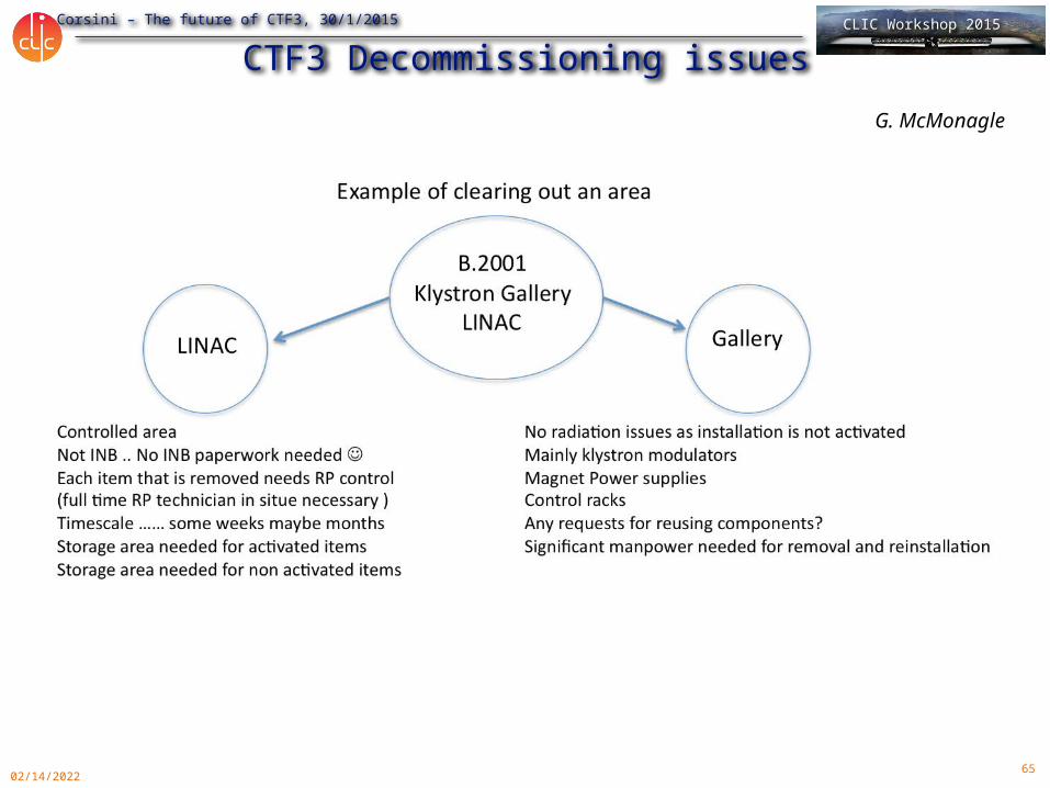
CTF3 Decommissioning issuesG. McMonagle
66
R. Corsini – The future of CTF3, 30/1/2015 CLIC Workshop 2015
05/01/2023
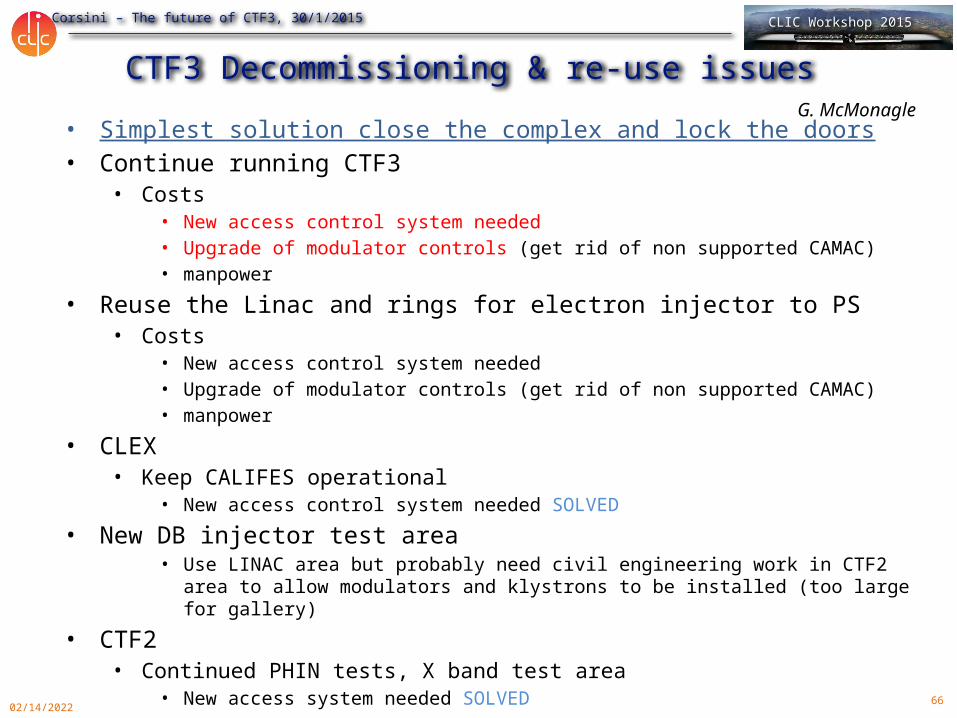
CTF3 Decommissioning & re-use issues • Simplest solution close the complex and lock the doors• Continue running CTF3
• Costs• New access control system needed• Upgrade of modulator controls (get rid of non supported CAMAC)• manpower
• Reuse the Linac and rings for electron injector to PS• Costs
• New access control system needed• Upgrade of modulator controls (get rid of non supported CAMAC)• manpower
• CLEX• Keep CALIFES operational
• New access control system needed SOLVED• New DB injector test area
• Use LINAC area but probably need civil engineering work in CTF2 area to allow modulators and klystrons to be installed (too large for gallery)
• CTF2• Continued PHIN tests, X band test area
• New access system needed SOLVED
G. McMonagle
67
R. Corsini – The future of CTF3, 30/1/2015 CLIC Workshop 2015
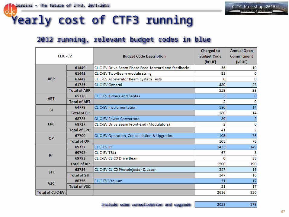
Yearly cost of CTF3 running2012 running, relevant budget codes in blue
Include some consolidation and upgrade
68
R. Corsini – The future of CTF3, 30/1/2015 CLIC Workshop 2015
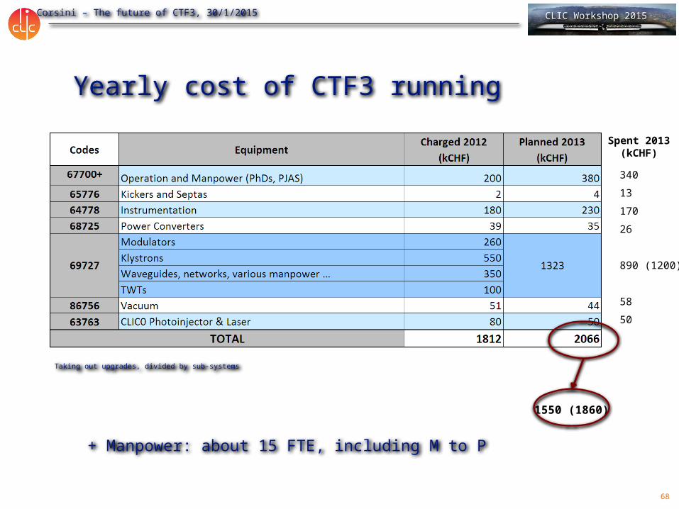
Yearly cost of CTF3 running
Taking out upgrades, divided by sub-systems
340
13
170
26
890 (1200)
58
50
+ Manpower: about 15 FTE, including M to P
1550 (1860)
Spent 2013(kCHF)
69
R. Corsini – The future of CTF3, 30/1/2015 CLIC Workshop 2015
05/01/2023
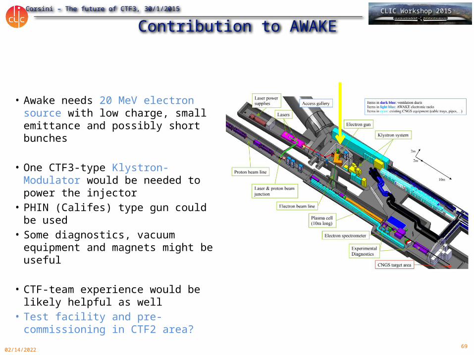
Contribution to AWAKE
• Awake needs 20 MeV electron source with low charge, small emittance and possibly short bunches
• One CTF3-type Klystron-Modulator would be needed to power the injector
• PHIN (Califes) type gun could be used
• Some diagnostics, vacuum equipment and magnets might be useful
• CTF-team experience would be likely helpful as well
• Test facility and pre-commissioning in CTF2 area?