the first valve manufacturer in the kingdomspazio per ... - ivm omb...
TRANSCRIPT

C-FVS

ww
w.iv
m-o
mbs
audi
.com
2
INDUSTRIAL VALVE MANUFACTURER is a Saudi owned and operated company which machine,assemble and test valves in the second industrial town in Al-Khobar.The company license the valves design and technology from OMB valves in Italy, with whon it hasa strong industrial and commercial relationship since its founding: OMB valves group provide as wellprocuremenet and training support allowing IVM to access the most reliable European suppliersof forgings and valve parts.
North America
South America
Europa
Africa
Asia
Middle East

ww
w.ivm-om
bsaudi.com
3
SPAZIO PER IL TITOLOw
ww.ivm
-ombsaudi.com
3
THE FIRST VALVE MANUFACTURER IN THE KINGDOM
A licensed forged valvemanufacturer in the Kingdom hasacquired the speciality of one of theleading manufacturer of forgedvalves in the world. Industrial ValvesManufacturer has beenmanufacturing a growing range offorged steel gate, globe and checkvalves to API/ASME specifications.The licensor company OMB valves S.p.A. based in Bergamo specialises in large scale manufacturing of valvesfor the petro - chemical industryranking second in the world foroutput. The Saudi operation bycontrast, is a small flexible team witha capability to manufacture up toten thousand valves per month andprovide a customization and quickdelivery service.
INDUSTRIAL VALVESMANUFACTURER (LICENSOROF OMB VALVES PRODUCTS)Industrial Valves Manufacturer is apart of a network of worldwide valvesupply through OMB, an italianbased group with 5 manufacturingplants, and its distribution partners.OMB manufactures valves in Italy,Singapore, UK and a Kingdom ofSaudi Arabia, with a team of morethan 200 engineers and valvespecialists and 6 specialized plants.OMB products range starts fromAPI602 gate, globe and check valvesin any material, to cryogenic service,bellows sealed and specializedchemical service valves.In Italy, OMB manufactures floating,trunnion and top entry ball valves upto 60’’ A complete set of cataloguescan be requested in any of OMB sitesor at OMB Agents and Distributorslocated in 50 countries and at over70 locations.
ww
w.iv
m-o
mbs
audi
.com
4
QUALIFICATIONS
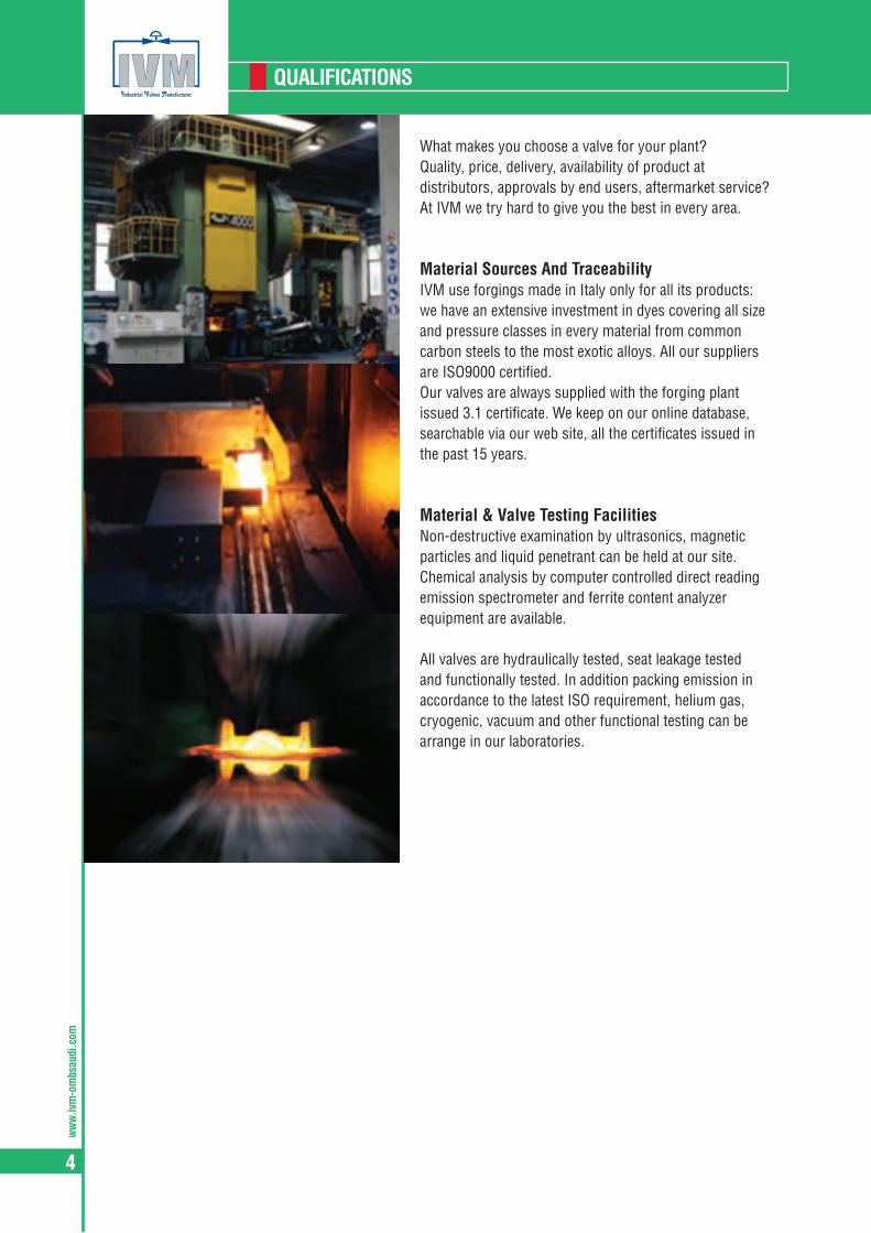
What makes you choose a valve for your plant?Quality, price, delivery, availability of product at distributors, approvals by end users, aftermarket service?At IVM we try hard to give you the best in every area.
Material Sources And TraceabilityIVM use forgings made in Italy only for all its products: we have an extensive investment in dyes covering all size and pressure classes in every material from common carbon steels to the most exotic alloys. All our suppliers are ISO9000 certified.Our valves are always supplied with the forging plant issued 3.1 certificate. We keep on our online database, searchable via our web site, all the certificates issued in the past 15 years.
Material & Valve Testing FacilitiesNon-destructive examination by ultrasonics, magnetic particles and liquid penetrant can be held at our site. Chemical analysis by computer controlled direct reading emission spectrometer and ferrite content analyzer equipment are available.
All valves are hydraulically tested, seat leakage tested and functionally tested. In addition packing emission in accordance to the latest ISO requirement, helium gas, cryogenic, vacuum and other functional testing can be arrange in our laboratories.

ww
w.ivm-om
bsaudi.com
5
MANUFACTURING STANDARDS
ISO 15761 has been recently published as part of an international effort to standardize the products for the Petroleum and Natural Gas industries. At printing time the list of ISO standards in our industry can be summarized in the following table. We list as well the major API and ASME standards covering our industry to which we refer in some of our following pages.
DESIGN AND MANUFACTURING STANDARDS
ISO API/ASME DESCRIPTIONISO 5208:1993 Industrial valves – Pressure testing of valves
ISO 5209:1977 General purpose industrial valves – Marking
ISO 5752:1982 Metal valves for use in flanged pipe systems – Face-to-face and centre-to-face dimensions
ISO 5996:1984 Cast iron gate valves
ISO 6002:1992 Bolted bonnet steel gate valves
ISO 7121:1986 Flanged steel ball valves
ISO 7259:1988 Predominantly key-operated cast iron gate valves for underground use
ISO 10423:2003 API 6A Specification for Wellhead and Christmas Tree Equipment
ISO 10434:2004 API 600 Bolted bonnet steel gate valves for the petroleum, petrochemical and aligned industries
ISO 10497:2004 API 607 Testing of valves - Fire type-testing requirements (Fire Test for Soft-Seated Quarter-Turn Valves)
ISO 10631:1994 Metallic butterfly valves for general purposes
ISO 12149:1999 Bolted bonnet steel globe valves for general-purpose applications
ISO 14313 API 6D Specification for Pipeline Valves
ISO 15156 NACE MR0175 NACE MR0175, Petroleum and natural gas industries—Materials for use in H2S-containing environments in oil and gas production
ISO 15761:2002 API 602 (including former BS5352)
Steel gate, globe and check valves for sizes DN 100 and smaller,for the petroleum and natural gas industries
ISO 15848-1:2006 Industrial valves –- Measurement, test and qualification procedures for fugitive emission Part 1: Classification system and qualification procedures for type testing of valves
ISO 17292:2004 Metal ball valves for petroleum, petrochemical and aligned industries
API 591 User Acceptance of Refinery Valves
API 598 Valve Inspection and Testing
API 600 Steel Gate Valves
API 602 Compact Carbon Steel Gate Valves
API 603 Cast, Corrosion Resistant Gate Valves
API608 Metal Ball Valves—Flanged, Threaded and Butt-Welding Ends (150&300)
API 17D Specification for Subsea Wellhead and Christmas Tree Equipment
API 6FA Specification for Fire Test for Valves
API622 Type Testing of Process Valve Packing for Fugitive Emissions
ASME B16.34 Valves 2 Flanged, Threaded, and Buttwelded End
ASME B16.10 Face-to-Face and End-to-End Dimensions of Valves
ASME B16.5 Pipe Flanges and Flanged Fittings
ASME B16.25 Buttwelded Ends
ASME B16.11 Forged Fittings, Socket Welding and Threaded
ww
w.iv
m-o
mbs
audi
.com
6
DESIGN
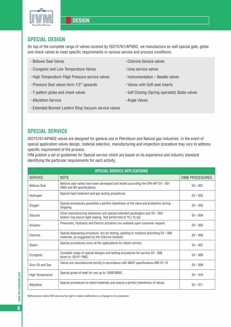
- Bellows Seal Valves
- Cryogenic and Low Temperature Valves
- High Temperature /High Pressure service valves
- Pressure Seal valves form 1/2” upwards
- Y pattern globe and check valves
- Alkylation Service
- Extended Bonnet/ Lantern Ring Vacuum service valves
- Chlorine Sersice valves
- Urea service valves
- Instrumentation – Needle valves
- Valves with Soft seat inserts
- Self Closing (Spring operated) Globe valves
- Angle Valves
On top of the complete range of valves covered by ISO15761/API602, we manufacture as well special gate, globe and check valves to meet specific requirements in various service and process conditions:
ISO15761/API602 valves are designed for general use in Petroleum and Natural gas industries. In the event of special application valves design, material selection, manufacturing and inspection procedure may vary to address specific requirement of the process.IVM publish a set of guidelines for Special service which are based on its experience and industry standard identifying the particular requirements for each activity.
Without prior notice IVM reserves the right to make modifications or changes to its production.
SPECIAL DESIGN
SPECIAL SERVICE
SPECIAL SERVICE APPLICATIONS
SERVICE NOTE OMB PROCEDURES
Bellows SealBellows seal valves have been developed and tested according the EPA-API SV - 001ANSI and BS specifications. SV - 001
HydrogenSpecial heat treatment and gas testing procedures.
SV - 002
OxygenSpecial procedures guarantee a perfect cleanliness of the valve and protection during shipping. SV - 003
VacuumClose manufacturing tolerances and special extended packingbox and SV - 004lantern ring assure tight sealing. Test performed at 10 (-4) bar. SV - 004
ActuatorPneumatic, Hydraulic and Electric actuators are available upon customer request.
SV - 005
ChlorineSpecial degreasing procedure, dry-air testing, packing in moisture absorbing SV - 006materials, as suggested by the Chlorine Institute. SV - 006
SteamSpecial procedures cover all the applications for steam service.
SV - 007
CryogenicComplete range of special designs and testing procedures for service SV - 008down to -521F/-196C. SV - 008
Sour Oil and GasValves are manufactured strictly in accordance with NACE specifications MR-01-75
SV - 009
High TemperatureSpecial grade of steel for use up to 1500F/800C.
SV - 010
AlkylationSpecial procedures to select materials and assure a perfect cleanliness of valves.
SV - 011
ww
w.ivm-om
bsaudi.com
7
MINIMUM FLOW PASSAGE WAY
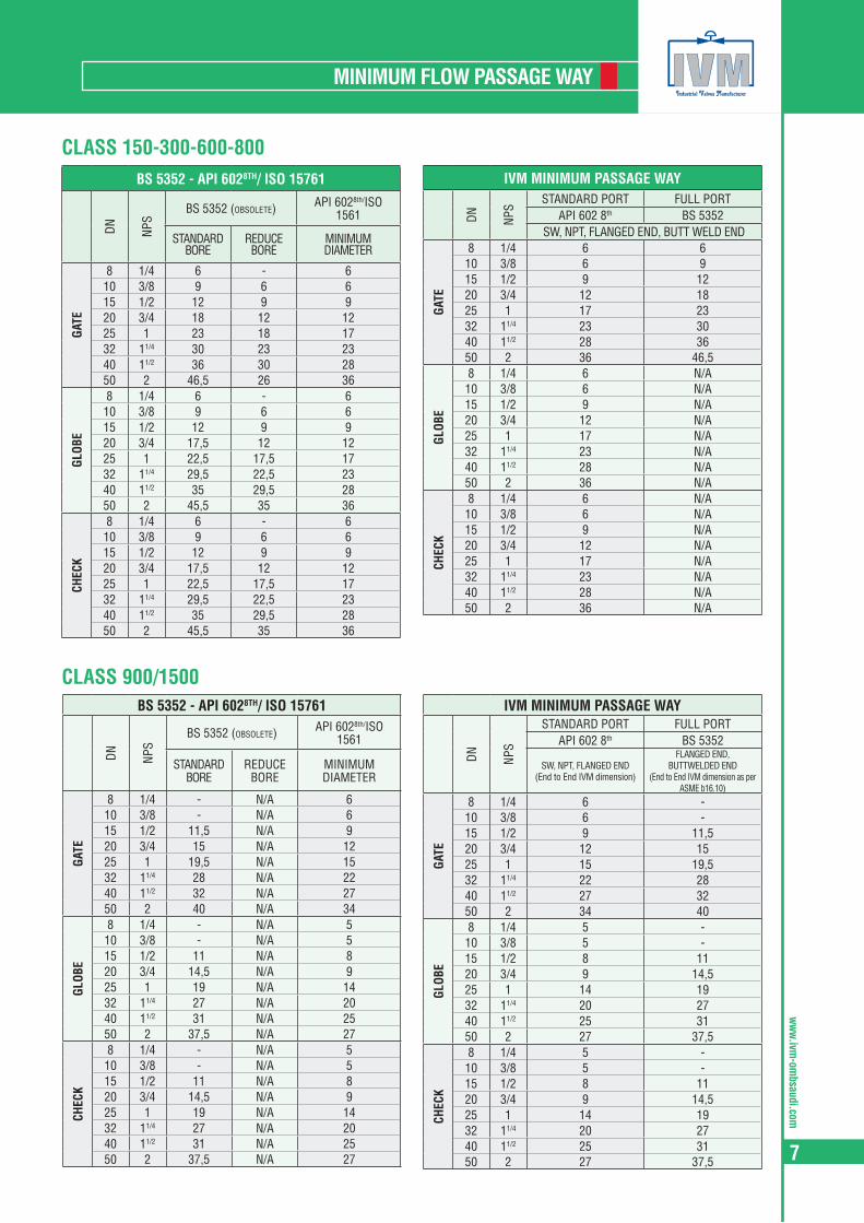
CLASS 150-300-600-800
CLASS 900/1500
BS 5352 - API 6028TH/ ISO 15761
DN NPS
BS 5352 (obsolete) API 6028th/ISO 1561
STANDARD BORE
REDUCE BORE
MINIMUM DIAMETER
GATE
8 1/4 6 - 610 3/8 9 6 615 1/2 12 9 920 3/4 18 12 1225 1 23 18 1732 11/4 30 23 2340 11/2 36 30 2850 2 46,5 26 36
GLOB
E
8 1/4 6 - 610 3/8 9 6 615 1/2 12 9 920 3/4 17,5 12 1225 1 22,5 17,5 1732 11/4 29,5 22,5 2340 11/2 35 29,5 2850 2 45,5 35 36
CHEC
K
8 1/4 6 - 610 3/8 9 6 615 1/2 12 9 920 3/4 17,5 12 1225 1 22,5 17,5 1732 11/4 29,5 22,5 2340 11/2 35 29,5 2850 2 45,5 35 36
IVM MINIMUM PASSAGE WAY
DN NPS
STANDARD PORT FULL PORTAPI 602 8th BS 5352
SW, NPT, FLANGED END, BUTT WELD END
GATE
8 1/4 6 610 3/8 6 915 1/2 9 1220 3/4 12 1825 1 17 2332 11/4 23 3040 11/2 28 3650 2 36 46,5
GLOB
E
8 1/4 6 N/A10 3/8 6 N/A15 1/2 9 N/A20 3/4 12 N/A25 1 17 N/A32 11/4 23 N/A40 11/2 28 N/A50 2 36 N/A
CHEC
K
8 1/4 6 N/A10 3/8 6 N/A15 1/2 9 N/A20 3/4 12 N/A25 1 17 N/A32 11/4 23 N/A40 11/2 28 N/A50 2 36 N/A
BS 5352 - API 6028TH/ ISO 15761
DN NPS
BS 5352 (obsolete) API 6028th/ISO 1561
STANDARD BORE
REDUCE BORE
MINIMUM DIAMETER
GATE
8 1/4 - N/A 610 3/8 - N/A 615 1/2 11,5 N/A 920 3/4 15 N/A 1225 1 19,5 N/A 1532 11/4 28 N/A 2240 11/2 32 N/A 2750 2 40 N/A 34
GLOB
E
8 1/4 - N/A 510 3/8 - N/A 515 1/2 11 N/A 820 3/4 14,5 N/A 925 1 19 N/A 1432 11/4 27 N/A 2040 11/2 31 N/A 2550 2 37,5 N/A 27
CHEC
K
8 1/4 - N/A 510 3/8 - N/A 515 1/2 11 N/A 820 3/4 14,5 N/A 925 1 19 N/A 1432 11/4 27 N/A 2040 11/2 31 N/A 2550 2 37,5 N/A 27
IVM MINIMUM PASSAGE WAY
DN NPS
STANDARD PORT FULL PORTAPI 602 8th BS 5352
SW, NPT, FLANGED END (End to End IVM dimension)
FLANGED END, BUTTWELDED END
(End to End IVM dimension as per ASME b16.10)
GATE
8 1/4 6 -10 3/8 6 -15 1/2 9 11,520 3/4 12 1525 1 15 19,532 11/4 22 2840 11/2 27 3250 2 34 40
GLOB
E
8 1/4 5 -10 3/8 5 -15 1/2 8 1120 3/4 9 14,525 1 14 1932 11/4 20 2740 11/2 25 3150 2 27 37,5
CHEC
K
8 1/4 5 -10 3/8 5 -15 1/2 8 1120 3/4 9 14,525 1 14 1932 11/4 20 2740 11/2 25 3150 2 27 37,5

ww
w.iv
m-o
mbs
audi
.com
8
MATERIALS
IVM valves are manufactured in a wide range of materials, supplied by the best available steel mills, forged by well known forge with outstanding equipment and experience. All the material can be certified in the chemical composition and the mechanical characteristic.
BODY AND BONNET MATERIALS
Material Group
Common Name Nominal Type UNS Forging Spec.
(ASTM)Casting Spec.
Equivalent DIN DIN W. No Application Notes
Carbon Steel CS C-Mn-Fe K03504 A105N A216-WCB C22.8 DIN 17243 1.0460 General non-corrosive service from -20F(-29C) to 800F(427C)
Low Temperature Carbon Steel TCS C-Mn-Fe K03011 A350-LF2 A352-LCA
A352-LCB - A352-LCC TSTE 355 DIN 18103 1.0566 General non-corrosive service from -50F(-46C) to 650F(340C), LF2 to 800F(427C).
Low Temperature Alloy Steel Nickel Steel 3.1/2Ni K32025 A350-LF3 A352-LC3 10Ni14 1.5637 -150F(-101C) to 650F(340C)
Low
Alloy
Stee
l
Moly Steel C-1/2Mo K12822 A182-F1 A217-WC1 15MO3 1.5415 Up to 875F (468C)
Alloy
Stee
l Ch
rom
e Moly
1.1/4Cr-1/2Mo K11572 A182-F11 cl2 A217-WC6 13CRMO44 1.7335 Up to 1100F (593C)
2.1/4Cr-1Mo K21590 A182-F22 cl3 A217-WC9 10CRMO910 1.7380 Up to 1100F(593C), HP steam
5Cr-1/2Mo K41545 A182-F5 A217-C5 12CRMO195 1.7362 High temp refinery service
9Cr-1Mo K90941 A182-F9 A217-C12 X 12 CrMo 91 1.7386 High temp erosive refinery service
9Cr-1Mo-V A182-F91 A217-C12A X 10 CrMoVNb 9 1 1.4903 High pressure steam
Stain
less S
teel
Auste
nitic
S.St
eel 3
00 se
ries S
.Stee
l
304 : 18Cr-8Ni S30400 A182-F304 A351-CF8 DIN X5CrNi 18 9 1.4301 0.04% min. carbon for temp.>1000F(538C)
304L : 18Cr-8Ni S30403 A182-F304L A351-CF3 X 2 CrNi 19 11 1.4306 Up to 800F(427C)
304H S30409 A182-F304H n/a n/a
316 : 16Cr-12Ni-2Mo S31600 A182-F316 A351-CF8M DIN X5CrNiMo 18 10 1.4401 0.04% min. carbon for temp.>1000F(538C)
316L : 16Cr-12Ni-2Mo S31603 A182-F316L A351-CF3M X 5 CrNiMo 17 12 2 1.4404 Up to 800F(427C)
316H S31609 A182-F316H n/a n/a
316Ti S31635 A182-F316Ti X 6 CrNiMoTi 17 12 2 1.4571
321: 18Cr-10Ni-Ti S32100 A182-F321 X 6 CrNiTi 18 10 1.4541 0.04% min. carbon (grade F321H) and heat treat at2000F(1100C) for service temps.>1000F(538C)
321H S32109 A182-F321H n/a n/a
347: 18Cr-10Ni-Cb(Nb) S34700 A182-F347 A351-CF8C DIN 8556 1.4550
0.04% min. carbon (grade F347H) and heat treat at2000F(1100C) for service temps.>1000F(538C)
347H S34709 A182-F347H n/a n/a
317L S31703 A182-F317L A351-CG3M X2CrNiMo18-16-4 1.4438
Alloy 20 28Ni-19Cr-Cu-Mo N08020 A182-F20 A351-CN7M DIN 1.4500 2.4660 service to 600F(316C)
Duplex 2205 22Cr-5Ni-3Mo-N S31803 S32205 A182-F51 A890-J92205 X2CrNiMON22-5-3
DIN 10088-1 (95) 1.4462service to 600F(316C) - The original S31803 UNS desig-
nation has been supplemented by S32205 which hashigher minimum N, Cr, and Mo.
Super Duplex 2507 25Cr-7Ni-4Mo-N S32750 A182-F53 A351-CD4MCu
A890 5AX2CrNiMoN25-7-4 DIN 10088-1 (95) 1.4501 service to 600F(316C)
Super Duplex F55 25Cr-7Ni-3.5Mo-N-Cu-W S32760 A182 F55 CD3MWCuN Service to 600F
Super Austenitic 6Mo 20Cr-18Ni-6Mo S31254 A182-F44 A351-CK3MCuN 1CrNiMoCuN20-18-7
DIN 10088-1 (95) 1.4547 service to 600F(316C)
Nickel-Iron AlloyIncoloy 800 33Ni-42Fe-21Cr N08800 B564-N08800 X10NiCrAlTi32-20 1.4876 service to 1000F(538C)
Incoloy 825 42Ni-21.5Cr-3Mo-2.3Cu N08825 B564-N08825 A494-CU5MCuC DIN 17744 2.4858N service to 600F(316C) for N02200, 1200F(648C)
forN02201
Nickel Nickel 99/95Ni N02200 B160-N02200 (bar) A494-CZ-100 NW2200 1.7740
Nickel-CopperMonel 400 67Ni-30Cu N04400 B564-N04400 A494-M35-1 DIN 17730 2.4360
Monel 500 N05500 B564-N05500 2.4375
Nickel-Alloy 904L N08904 904L n/a Z2 NCDU 25-20 1.4539
Nickel Superalloys
Inconel 600 72Ni-15Cr-8Fe N06600 B564-N06600 A494-CY40 DIN 17742 2.4816
Inconel 625 60Ni-22Cr-9Mo-3.5Cb N06625 B564-N06625* A494-CW-6MC 2.4856 *Difficult to forge in close dye
Hastelloy C-276 54Ni-15Cr-16Mo N10276 B564-N10276* A494-CW-2M A494-CW-2M NiMo 16 Cr 15 W 2.4819 *Difficult to forge in close dye
Titanium Titanium 98Ti R50400 B381-Gr2 B367-C2 Ti 2 3.7035

ww
w.ivm-om
bsaudi.com
9
MATERIALS
The following tables suggest standard combination of body and bonnet materials and trim (stem, disc or wedge, seat) composition. Different combinations are available upon request.
BOLTS MATERIALS
IVM STANDARD TRIM DEFINITIONS
API Trim No Nominal Trim IVM descr. Steam Disc/Wedge Seat Min Hardness (Brinell)
1 F6 F6 410 (13Cr) F6 (13Cr) 410 (13Cr) 250
2 304 304 304 (18Cr-8Ni) 304 (18Cr-8Ni) 304 (18Cr-8Ni) not specified
3 - - (25Cr-20Ni) 310 (25Cr-20Ni) 310 (25Cr-20Ni) not specified
4 - - 410 (13Cr) F6 (13Cr) F6 (13Cr) 750
5 Hardfaced F6HF 410 (13Cr) F6 + St Gr6 (CoCr Alloy) 410 + St Gr6 (CoCr Alloy) 350
5A - - 410 (13Cr) F6+Hardf. NiCr Alloy 410+Hardf. NiCr Alloy 350
6 - - 410 (13Cr) F6 (13CR) Monel® (NiCu Alloy) 250/175
7 - - 410 (13Cr) F6 (13CR) F6 (13Cr) 250/750
8 F6 and Hardfaced F6HFS 410 (13Cr) F6 (13CR) 410 + St Gr6 (CoCr Alloy) 250/350
8A - - 410 (13Cr) F6 (13CR) 410 Hardf. Nicr Alloy 250/350
9 Monel Monel Monel®(NiCu Alloy) Monel®(NiCu Alloy) Monel®(NiCu Alloy) not specified
10 316 316 316 (18Cr-8Ni-Mo) 316 (18Cr-8Ni-Mo) 316 (18Cr-8Ni-Mo) not specified
11 Monel and Hardfaced MonelHFS Monel®(NiCu Alloy) Monel®(NiCu Alloy) Monel®St Gr6 350
11A - - Monel®(NiCu Alloy) Monel®(NiCu Alloy) Monel®Hardif. NiCrA 3350
12 316 and Hardfaced 316HFS 316 (18Cr-8Ni-Mo) 316 (18Cr-8Ni-Mo) 316 + St. Gr6 350
12A - - 316 (18Cr-8Ni-Mo) 316 ( 18Cr-8Ni-Mo) 316 Hardf. NiCr Alloy 350
13 Alloy 20 Alloy 20 Alloy 20 (19Cr-29Ni) Alloy 20 (19Cr-29Ni) Alloy 20 (19Cr-29Ni) not specified
14 Alloy 20 and Hardfaced Alloy 20HFS Alloy 20 (19Cr-29Ni) Alloy 20 (19Cr-29Ni) Alloy 20 St Gr6 350
14A - - Alloy 20 (19Cr-29Ni) Alloy 20 (19Cr-29Ni) Alloy 20 Hardf. NiCr Alloy 350
15 Hardfaced (304) 304-HF 304 (18Cr-8Ni) 304 + St Gr6 304 + St Gr6 350
16 Hardfaced (316) 316-HF - 316 + St Gr6 316 + St Gr6 350
17 Hardfaced (347) 347-HF - 347 + St Gr6 347 + St Gr6 350
18 Hardfaced Alloy 20 HF Alloy 20 HF Alloy 20 (19Cr-29Ni) Alloy 20 + St Gr6 Alloy 20 + St Gr6 350
n/a Alloy 625 Alloy 625 Alloy 625 Alloy 625 Alloy 625 -
IVM TRIM MATERIAL
OMB UNS TYPE Grade (forged) ASTM wrought DIN DIN W No
F6 UNS S41000 13Cr ASTM A182 F6a A276-410 DIN X12Cr13 1.4006
304 UNS S30400 18-8 Cr-Ni ASTM A182 F304 A276-304 DIN X5CrNi 18 10 1.4301
316 UNS S31600 18-8 Cr-Ni (18-10-2) ASTM A182 F316 A276-316 DIN X5CrNiMo 18 10 1.4401
321 UNS S32100 18 Cr-10 Ni-Ti ASTM A182 F321 A276-321 DIN X6CrNiTi 18 10 1.4541
347 UNS S34700 18 Cr-10 Ni-Cb ASTM A182 F347 A276-347 DIN X6CrNiNb18 10 1.4550
MONEL® UNS N04400 67Ni-30Cu ASTM B564-N04400 B164-N04400 DIN 17743 2.4360
ALLOY 20 UNS N08020 28Ni-19Cr-Cu-Mo ASTM A182-F20 ASTM B473 DIN 14500 2.4660
ALLOY 625 UNS N06625 60Ni-22Cr-9Mo-3.5Cb ASTM B564-N06625 ASTM B564-N06625 DIN 17361 2.4865
C276 UNS N10276 54Ni-15Cr-16Mo ASTM B564-N10276 ASTM B574-N10276 DIN NiMo 16 Cr 15 W 2.4819
17/4PH UNS S17400 0Cr17Ni4Cu4Nb ASTM A705 UNS S17400 ASTM A564 UNS S17400 X5CrNiCuNb17-4-4 1.4548
St. Gr6 UNS R30006 Co Cr-A AMS 5894 Stellite(R) Gr6

ww
w.iv
m-o
mbs
audi
.com
10
PACKING AND GASKET
ASBESTOS-FREE PACKING is composed by a series of rings of pure graphite. The sets is closed with two rings, top and bottom, anti-extrusion, manufactured in braided graphite. Both internal and external rings are treated with corrosion inhibitor.ASBESTOS-FREE GASKETS used on bolted bonnet valves are of the spiral-wound type in Stainless Steel 316 and pure graphite. On class 1500 valves, ring-joint gaskets in accordance with ANSI B16.20 - API 6A can be used.SPARE PARTS IVM mantains an extensive inventory of packing and gasket spares. To individualise the required one please refer to the information shown on IVM’s data sheets (assembly drawings), indicating code and composition of the sets. A comprehensive updated list of packing and gasket for each design/figure is available online at www.ivm-ombsaudi.it.com
IVM offers a wide range of solutions to control fugitive emissions in packed valves.EMISSION CONTROL OPTIONS
EMISSION CONTROL TESTING & QUALIFICATION
GRAPHITE PACKINGTight control on stem and packing chamber walls finishing and material purity and density in the packing guarantee a leakproof sealing to EPA requisitions.
LANTERN PACKING (on request)The lantern ring solutionprovide a way to verify thepacking operation and agrease injector option toincrease packing seal.
LIVE LOADINGBolts loaded type
(on request)Two sets of Belleville springs keep gland flange pressure on packing for long periods of time without maintenance.
LIVE LOADING Gland loaded type
(on request)Sets of belleville springskeep gland pressure onpacking for long periods oftime without maintenance.
GARLOCK®
EVSP 9000 FVP(on request)OMB offers this superior designed chevron-style graphite packing. ISA testing qualification for BP.
ARMA-SEAL 312 (TM)
(on request)IVM valves qualified toISO15848 testing using this special designed packing.Shell 77/312 qualification.
PATENTED
PATENTED
ISO TESTINGValve cycle tester using a mass spectrometer in sniffer mode to measure helium leakage from the
valve gland.
OMB has beeninvolved in extensivetesting of variouspacking solutionswhich lead to majorimprovements in thestandard design andqualification by themain relevantspecifications.
ISO 15848 TESTINGEmission test with
Temperature and Pressure cycles combined.Detection by mass
spectrometer in open ambient.
API 622 TESTINGValve temperature and
pressure cycle with methane.
ww
w.ivm-om
bsaudi.com
11
MATERIALS
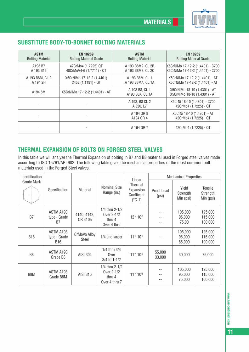
In this table we will analyze the Thermal Expansion of bolting in B7 and B8 material used in Forged steel valves made according to ISO 15761/API 602. The following table gives the mechanical properties of the most common bolt materials used in the Forged Steel valves.
SUBSTITUTE BODY-TO-BONNET BOLTING MATERIALS
THERMAL EXPANSION OF BOLTS ON FORGED STEEL VALVES
ASTM Bolting Material
EN 10269 Bolting Material Grade
ASTM Bolting Material
EN 10269 Bolting Material Grade
A193 B7 A 193 B16
42CrMo4 (1.7225) QT 40CrMoV4-6 (1.7711) - QT
A 193 B8M2, CL 2B A 193 B8M3, CL 2C
X5CrNiMo 17-12-2 (1.4401) - C700 X5CrNiMo 17-12-2 (1.4401) - C700
A 193 B8M, CL 2 A 194 2H
X5CrNiMo 17-12-2 (1.4401) C45E (1.1191) - QT
A 193 B8M, CL 1 A 193 B8MA, CL 1A
X5CrNiMo 17-12-2 (1.4401) - AT X5CrNiMo 17-12-2 (1.4401) - AT
A194 8M X5CrNiMo 17-12-2 (1.4401) - AT A 193 B8, CL 1 A193 B8A, CL 1A
X5CrNiMo 18-10 (1.4301) - AT X5CrNiMo 18-10 (1.4301) - AT
- - A 193, B8 CL 2 A 320, L7
X5CrNi 18-10 (1.4301) - C700 42CrMo4 (1.7225) - QT
- - A 194 GR 8 A194 GR 4
X5CrNi 18-10 (1.4301) - AT 42CrMo4 (1.7225) - QT
- - A 194 GR 7 42CrMo4 (1.7225) - QT
IdentificationGrnde Mark
Specification Material Nominal SizeRange (in.)
Linear Thermal
Expansion Coefficent
(°C-1)
Mechanical Properties
Proof Load(psi)
Yield StrengthMin (psi)
Tensile StrengthMin (psi)
B7ASTM A193type - Grade
B7
4140, 4142,OR 4105
1/4 thru 2-1/2Over 2-1/2
thru 4Over 4 thru
12* 10-6------
105,00095,00075,00
125,000115,000100,000
B16ASTM A193type - Grade
B16
CrMoVa AlloySteel 1/4 and larger 11* 10-6 --
105,00095,00085,000
125,000115,000100,000
B8 ASTM A193Grade B8 AISI 304
1/4 thru 3/4 Over
3/4 to 1-1/211* 10-6 55,000
33,000 30,000 75,000
B8M ASTM A193Grade B8M AISI 316
1/4 thru 2-1/2Over 2-1/2
thru 4Over 4 thru 7
11* 10-6------
105,00095,00075,000
125,000115,000100,000
ww
w.iv
m-o
mbs
audi
.com
12
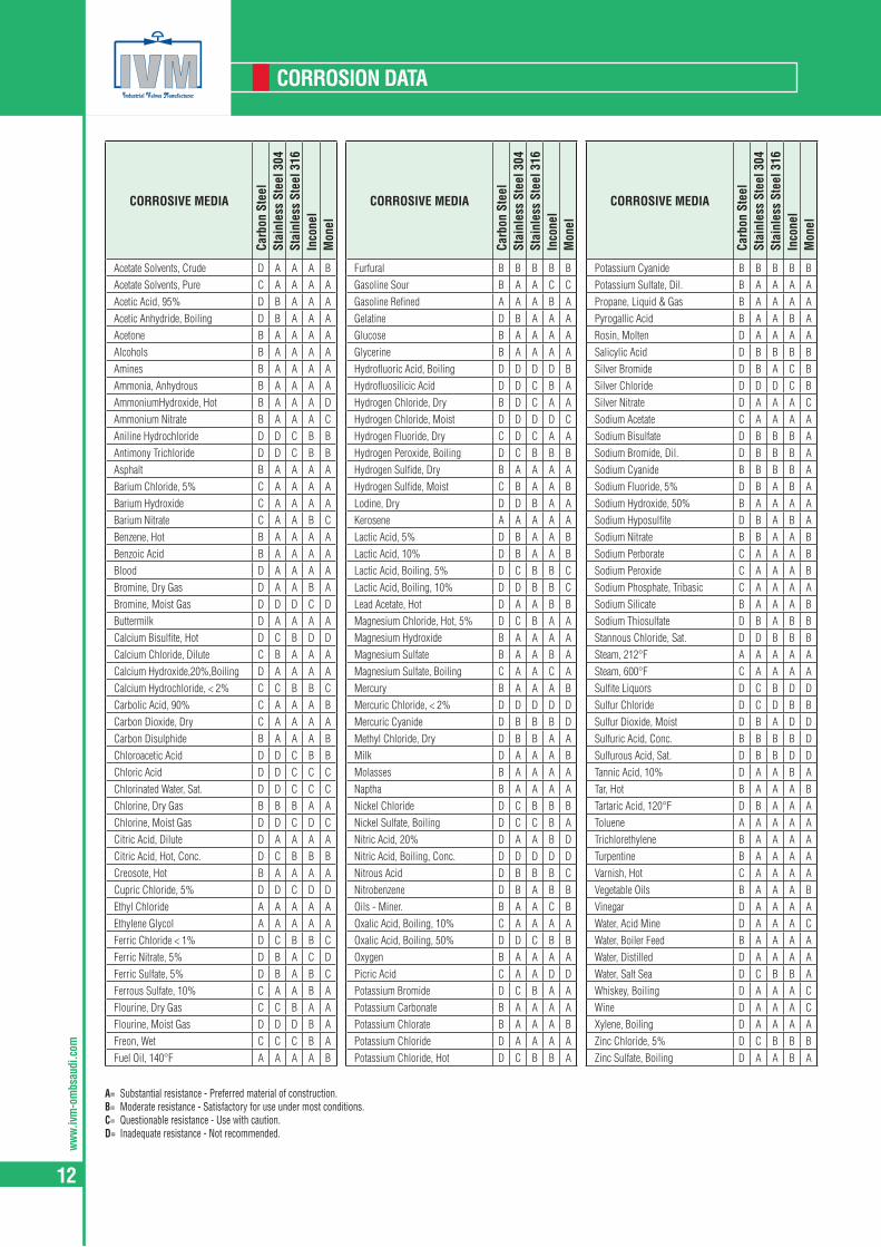
CORROSION DATA
A= Substantial resistance - Preferred material of construction.B= Moderate resistance - Satisfactory for use under most conditions.C= Questionable resistance - Use with caution.D= Inadequate resistance - Not recommended.
CORROSIVE MEDIA
Carb
on S
teel
Stai
nles
s St
eel 3
04St
ainl
ess
Stee
l 316
Inco
nel
Mon
el
Acetate Solvents, Crude D A A A BAcetate Solvents, Pure C A A A AAcetic Acid, 95% D B A A AAcetic Anhydride, Boiling D B A A AAcetone B A A A AAlcohols B A A A AAmines B A A A AAmmonia, Anhydrous B A A A AAmmoniumHydroxide, Hot B A A A DAmmonium Nitrate B A A A CAniline Hydrochloride D D C B BAntimony Trichloride D D C B BAsphalt B A A A ABarium Chloride, 5% C A A A ABarium Hydroxide C A A A ABarium Nitrate C A A B CBenzene, Hot B A A A ABenzoic Acid B A A A ABlood D A A A ABromine, Dry Gas D A A B ABromine, Moist Gas D D D C DButtermilk D A A A ACalcium Bisulfite, Hot D C B D DCalcium Chloride, Dilute C B A A ACalcium Hydroxide,20%,Boiling D A A A ACalcium Hydrochloride, < 2% C C B B CCarbolic Acid, 90% C A A A BCarbon Dioxide, Dry C A A A ACarbon Disulphide B A A A BChloroacetic Acid D D C B BChloric Acid D D C C CChlorinated Water, Sat. D D C C CChlorine, Dry Gas B B B A AChlorine, Moist Gas D D C D CCitric Acid, Dilute D A A A ACitric Acid, Hot, Conc. D C B B BCreosote, Hot B A A A ACupric Chloride, 5% D D C D DEthyl Chloride A A A A AEthylene Glycol A A A A AFerric Chloride < 1% D C B B CFerric Nitrate, 5% D B A C DFerric Sulfate, 5% D B A B CFerrous Sulfate, 10% C A A B AFlourine, Dry Gas C C B A AFlourine, Moist Gas D D D B AFreon, Wet C C C B AFuel Oil, 140°F A A A A B
CORROSIVE MEDIA
Carb
on S
teel
Stai
nles
s St
eel 3
04St
ainl
ess
Stee
l 316
Inco
nel
Mon
el
Furfural B B B B BGasoline Sour B A A C CGasoline Refined A A A B AGelatine D B A A AGlucose B A A A AGlycerine B A A A AHydrofluoric Acid, Boiling D D D D BHydrofluosilicic Acid D D C B AHydrogen Chloride, Dry B D C A AHydrogen Chloride, Moist D D D D CHydrogen Fluoride, Dry C D C A AHydrogen Peroxide, Boiling D C B B BHydrogen Sulfide, Dry B A A A AHydrogen Sulfide, Moist C B A A BLodine, Dry D D B A AKerosene A A A A ALactic Acid, 5% D B A A BLactic Acid, 10% D B A A BLactic Acid, Boiling, 5% D C B B CLactic Acid, Boiling, 10% D D B B CLead Acetate, Hot D A A B BMagnesium Chloride, Hot, 5% D C B A AMagnesium Hydroxide B A A A AMagnesium Sulfate B A A B AMagnesium Sulfate, Boiling C A A C AMercury B A A A BMercuric Chloride, < 2% D D D D DMercuric Cyanide D B B B DMethyl Chloride, Dry D B B A AMilk D A A A BMolasses B A A A ANaptha B A A A ANickel Chloride D C B B BNickel Sulfate, Boiling D C C B ANitric Acid, 20% D A A B DNitric Acid, Boiling, Conc. D D D D DNitrous Acid D B B B CNitrobenzene D B A B BOils - Miner. B A A C BOxalic Acid, Boiling, 10% C A A A AOxalic Acid, Boiling, 50% D D C B BOxygen B A A A APicric Acid C A A D DPotassium Bromide D C B A APotassium Carbonate B A A A APotassium Chlorate B A A A BPotassium Chloride D A A A APotassium Chloride, Hot D C B B A
CORROSIVE MEDIA
Carb
on S
teel
Stai
nles
s St
eel 3
04St
ainl
ess
Stee
l 316
Inco
nel
Mon
el
Potassium Cyanide B B B B BPotassium Sulfate, Dil. B A A A APropane, Liquid & Gas B A A A APyrogallic Acid B A A B ARosin, Molten D A A A ASalicylic Acid D B B B BSilver Bromide D B A C BSilver Chloride D D D C BSilver Nitrate D A A A CSodium Acetate C A A A ASodium Bisulfate D B B B ASodium Bromide, Dil. D B B B ASodium Cyanide B B B B ASodium Fluoride, 5% D B A B ASodium Hydroxide, 50% B A A A ASodium Hyposulfite D B A B ASodium Nitrate B B A A BSodium Perborate C A A A BSodium Peroxide C A A A BSodium Phosphate, Tribasic C A A A ASodium Silicate B A A A BSodium Thiosulfate D B A B BStannous Chloride, Sat. D D B B BSteam, 212°F A A A A ASteam, 600°F C A A A ASulfite Liquors D C B D DSulfur Chloride D C D B BSulfur Dioxide, Moist D B A D DSulfuric Acid, Conc. B B B B DSulfurous Acid, Sat. D B B D DTannic Acid, 10% D A A B ATar, Hot B A A A BTartaric Acid, 120°F D B A A AToluene A A A A ATrichlorethylene B A A A ATurpentine B A A A AVarnish, Hot C A A A AVegetable Oils B A A A BVinegar D A A A AWater, Acid Mine D A A A CWater, Boiler Feed B A A A AWater, Distilled D A A A AWater, Salt Sea D C B B AWhiskey, Boiling D A A A CWine D A A A CXylene, Boiling D A A A AZinc Chloride, 5% D C B B BZinc Sulfate, Boiling D A A B A
ww
w.ivm-om
bsaudi.com
13
PRESSURE - TEMPERATURE RATINGS
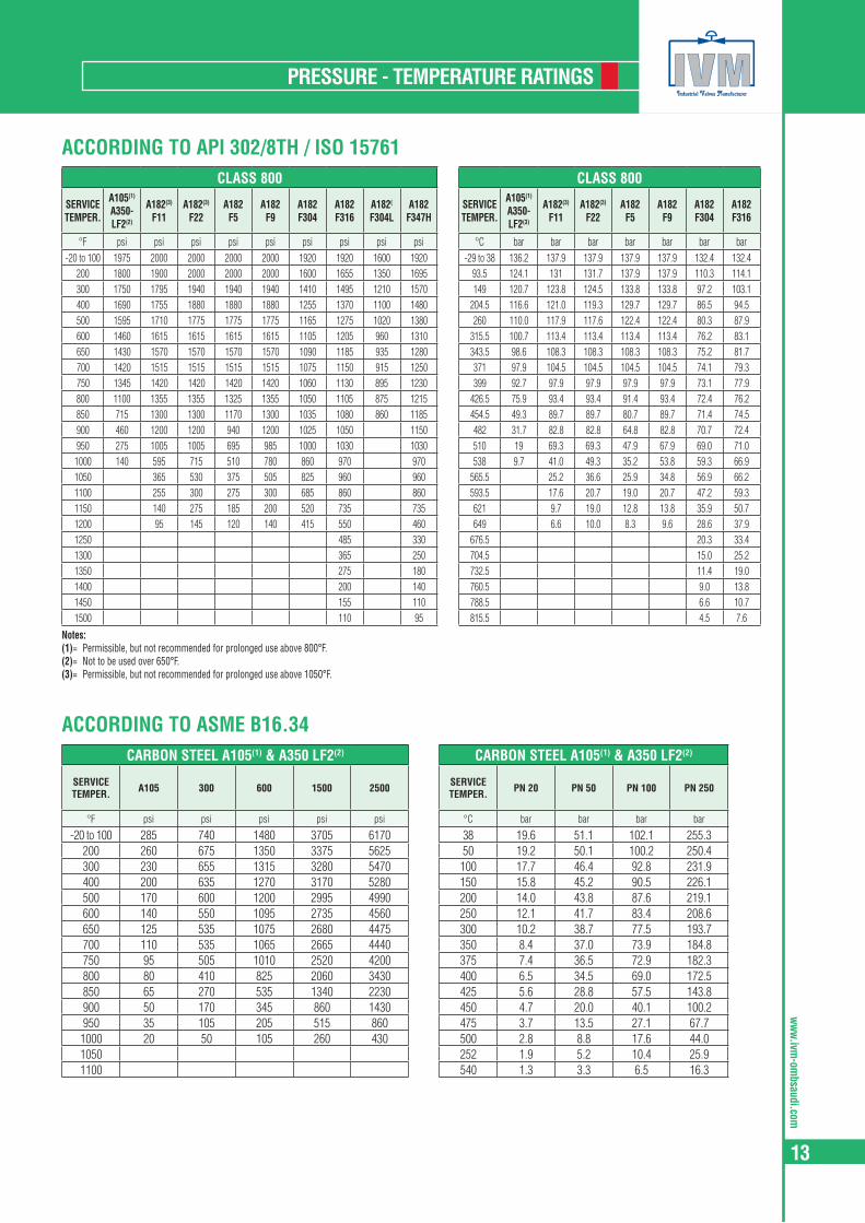
ACCORDING TO API 302/8TH / ISO 15761
ACCORDING TO ASME B16.34
CLASS 800
SERVICE TEMPER.
A105(1)
A350-LF2(2)
A182(3)
F11A182(3)
F22A182
F5A182
F9A182
F304A182
F316A182(
F304LA182
F347H
°F psi psi psi psi psi psi psi psi psi-20 to 100 1975 2000 2000 2000 2000 1920 1920 1600 1920
200 1800 1900 2000 2000 2000 1600 1655 1350 1695300 1750 1795 1940 1940 1940 1410 1495 1210 1570400 1690 1755 1880 1880 1880 1255 1370 1100 1480500 1595 1710 1775 1775 1775 1165 1275 1020 1380600 1460 1615 1615 1615 1615 1105 1205 960 1310650 1430 1570 1570 1570 1570 1090 1185 935 1280700 1420 1515 1515 1515 1515 1075 1150 915 1250750 1345 1420 1420 1420 1420 1060 1130 895 1230800 1100 1355 1355 1325 1355 1050 1105 875 1215850 715 1300 1300 1170 1300 1035 1080 860 1185900 460 1200 1200 940 1200 1025 1050 1150950 275 1005 1005 695 985 1000 1030 10301000 140 595 715 510 780 860 970 9701050 365 530 375 505 825 960 9601100 255 300 275 300 685 860 8601150 140 275 185 200 520 735 7351200 95 145 120 140 415 550 4601250 485 3301300 365 2501350 275 1801400 200 1401450 155 1101500 110 95
CLASS 800
SERVICE TEMPER.
A105(1)
A350-LF2(3)
A182(3)
F11A182(3)
F22A182
F5A182
F9A182
F304A182
F316
°C bar bar bar bar bar bar bar-29 to 38 136.2 137.9 137.9 137.9 137.9 132.4 132.4
93.5 124.1 131 131.7 137.9 137.9 110.3 114.1149 120.7 123.8 124.5 133.8 133.8 97.2 103.1
204.5 116.6 121.0 119.3 129.7 129.7 86.5 94.5260 110.0 117.9 117.6 122.4 122.4 80.3 87.9
315.5 100.7 113.4 113.4 113.4 113.4 76.2 83.1343.5 98.6 108.3 108.3 108.3 108.3 75.2 81.7371 97.9 104.5 104.5 104.5 104.5 74.1 79.3399 92.7 97.9 97.9 97.9 97.9 73.1 77.9
426.5 75.9 93.4 93.4 91.4 93.4 72.4 76.2454.5 49.3 89.7 89.7 80.7 89.7 71.4 74.5482 31.7 82.8 82.8 64.8 82.8 70.7 72.4510 19 69.3 69.3 47.9 67.9 69.0 71.0538 9.7 41.0 49.3 35.2 53.8 59.3 66.9
565.5 25.2 36.6 25.9 34.8 56.9 66.2593.5 17.6 20.7 19.0 20.7 47.2 59.3621 9.7 19.0 12.8 13.8 35.9 50.7649 6.6 10.0 8.3 9.6 28.6 37.9
676.5 20.3 33.4704.5 15.0 25.2732.5 11.4 19.0760.5 9.0 13.8788.5 6.6 10.7815.5 4.5 7.6
Notes:(1)= Permissible, but not recommended for prolonged use above 800°F.(2)= Not to be used over 650°F.(3)= Permissible, but not recommended for prolonged use above 1050°F.
CARBON STEEL A105(1) & A350 LF2(2)
SERVICE TEMPER. A105 300 600 1500 2500
°F psi psi psi psi psi
-20 to 100 285 740 1480 3705 6170200 260 675 1350 3375 5625300 230 655 1315 3280 5470400 200 635 1270 3170 5280500 170 600 1200 2995 4990600 140 550 1095 2735 4560650 125 535 1075 2680 4475700 110 535 1065 2665 4440750 95 505 1010 2520 4200800 80 410 825 2060 3430850 65 270 535 1340 2230900 50 170 345 860 1430950 35 105 205 515 8601000 20 50 105 260 43010501100
CARBON STEEL A105(1) & A350 LF2(2)
SERVICE TEMPER. PN 20 PN 50 PN 100 PN 250
°C bar bar bar bar
38 19.6 51.1 102.1 255.350 19.2 50.1 100.2 250.4100 17.7 46.4 92.8 231.9150 15.8 45.2 90.5 226.1200 14.0 43.8 87.6 219.1250 12.1 41.7 83.4 208.6300 10.2 38.7 77.5 193.7350 8.4 37.0 73.9 184.8375 7.4 36.5 72.9 182.3400 6.5 34.5 69.0 172.5425 5.6 28.8 57.5 143.8450 4.7 20.0 40.1 100.2475 3.7 13.5 27.1 67.7500 2.8 8.8 17.6 44.0252 1.9 5.2 10.4 25.9540 1.3 3.3 6.5 16.3

ww
w.iv
m-o
mbs
audi
.com
14
PRESSURE - TEMPERATURE RATINGS
ISO 15848 PART I - FUGITIVE EMISSION TEST MATRIXIVM valves completed the following test to qualify the complete product range with a major end user
TEST PROTOCOL NUMBER
Design Temp. Range 150-600 1500 2500
Gate Valves ISO 15761/ API602, Wedge Type, Metal Seated, Rising Stem valves, Cryogenic ext bonnet -196 to 300c 1 2 3
Gate Valves ISO 15761/ API602, Wedge Type, Metal Seated, Rising Stem valves std -50 to 400C 4 5 6
Gate Valves ISO 15761/ API602, Wedge Type, Metal Seated, Rising Stem valves, High Temp std 0 -650C 7 8 9
Globe Valves ISO 15761/ API602 (BS5352),Flanged, Plug/ball type, Cryogeinc
straight ext bonnet -196 to 300c 10 11 12
Globe Valves ISO 15761/ API602 (BS5352),Flanged, Plug/ball type straight -50 to 400C 13 14 15
Globe Valves ISO 15761/ API602 (BS5352),Flanged, Plug/ball type, High Temp straight 0 -650C 16 17 18
Globe Valves ISO 15761/ API602 (BS5352), Flanged, Plug/ball type Y pattern -50 to 400C 19 20 21
Globe Valves ISO 15761/ API602 (BS5352),Flanged, Plug/ball type, High Temp Y pattern 0 -650C 22 23 24
Check Valves ISO 15761/ API602 (BS5352),Piston Type, Bolted cover, cryogenic straight -196 to 300c 25 26 27
Check Valves ISO 15761/ API602 (BS5352), Piston Type, Bolted cover straight -50 to 400C 28 29 30
Check Valves ISO 15761/ API602 (BS5352),Piston Type, Welded cover, high temperature straight 0 -650C 31 30 33
ww
w.ivm-om
bsaudi.com
15
CONSTRUCTION
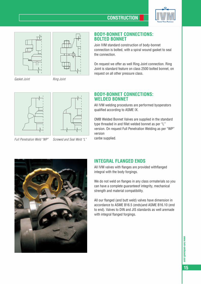
BODY-BONNET CONNECTIONS: BOLTED BONNETJoin IVM standard construction of body-bonnet connection is bolted, with a spiral wound gasket to seal the connection.
On request we offer as well Ring Joint connection. Ring Joint is standard feature on class 2500 bolted bonnet, on request on all other pressure class.
BODY-BONNET CONNECTIONS: WELDED BONNETAll IVM welding procedures are performed byoperators qualified according to ASME IX.
OMB Welded Bonnet Valves are supplied in the standard type threaded in and fillet welded bonnet as per “L” version. On request Full Penetration Welding as per “WP” versioncanbe supplied.
INTEGRAL FLANGED ENDSAll IVM valves with flanges are provided withflanged integral with the body forgings.
We do not weld on flanges in any class ormaterials so you can have a complete guaranteeof integrity, mechanical strength and material compatibility.
All our flanged (and butt weld) valves have dimension in accordance to ASME B16.5 (ends)and ASME B16.10 (end to end). Valves to DIN and JIS standards as well aremade with integral flanged forgings.
Gasket Joint
Full Penetration Weld “WP”
Ring Joint
Screwed and Seal Weld “L”

ww
w.iv
m-o
mbs
audi
.com
16
FLOW COEFFICIENT CHARTS
The Cv’s a valve property and is defined as follows: “The Flow Coefficient Cv states the flow capacity of a valve in U.S. gallons per minute of water at a standard temperature of 60°F (15,6° C) that will flow through the valve with apressure loss of one pound per square inch at a specific opening position”. For the metric system the analog value isKv where measure unit are Bar, Kg and meters. The Cv show the quality and accuracy of a valve in terms of pressureloss, the highest values of Cv indicate the highest quality of a valve.
To measure the properly value of Cv there in not a standard method. OMB R & D team has used two different methods:1) Using Cv definition, through the means of a specifically built test rig, it has been obtained 1Bar of pressure loss
and the flow has been verified with specific equipment. Calculation is possible to convert the measure to Cv.2) In the same machine the flow has been changed and different measure of pressure loss has been obtained:
a table has been defined and an average value per each valve has been calculated.
Disclaimer. All above data have been calculated experimentally on production lost based on a standard combination of materials tested with air. Data may vary withfluid of higher or with spring/parts in special steel grades. In case of specific need we suggest you contact OMB center at the Bergamo plants.
FLOW COEFFICENT CV
CHECK VALVES CRACKING PRESSURE
THE VALUES SHOWNVALVE SIZE
GATE GLOBE PISTON
Regular Port Full Port Regular Port Full Port Y-Pattern Regular Port Full Port Y-Pattern
1/4 - 2.5 - 1.1 - - 0.9 2.31/8 - 4.3 - 1.4 - - 1.1 3.51/2 5.5 11.6 1.5 3.6 1 1 2.1 4.83/4 12 26.6 3.8 6.6 2.8 2.8 5.8 7.81 27 54.6 6.8 10.9 6 6 7 11.2
11/4 55 79.8 11 14 9.5 9.5 9.2 18.011/2 80 87 14.3 24.3 11 11 15.4 37.82 105 108 25 39.7 18 18 32 69.2
CONVERSION TABLE TO METRI Kv
Flow Coefficent Cv Kv
Cv 1 0.865Kv 1.156 1
FLOW-RATE
PRESSURE DROP
For liquids other than waterp = Pressure drop (p.s.i.).Q = Liquid flow in gallons per minute (GPM).S = Specific gravity of liquid relative toater (60°F).Cv = Valves flow coefficent.
VALVE PISTON TYPE Y PATTERN PISTON TYPE BALL TYPE SWING VERTICAL BALL
Non Spring Loaded
Spring Loaded
Non Spring Loaded
Spring Loaded
Non Spring Loaded
Spring Loaded
Non Spring Loaded
Spring Loaded
NPS 840 840 Spring Y640 Y640 Spring 850 850 Spring 860 UV8501/2” - 15 0.4 Bar 0.5 Bar 0.4 Bar 0.5 Bar 0.3 Bar 0.4 Bar 0.03 Bar 0.4 Bar3/4 - 20 0.4 Bar 0.5 Bar 0.4 Bar 0.5 Bar 0.3 Bar 0.4 Bar 0.03 Bar 0.4 Bar1” - 25 0.4 Bar 0.5 Bar 0.4 Bar 0.5 Bar 0.3 Bar 0.4 Bar 0.03 Bar 0.4 Bar
1.1/2” - 40 0.4 Bar 0.5 Bar 0.4 Bar 0.5 Bar 0.3 Bar 0.4 Bar 0.04 Bar 0.4 Bar2” - 50 0.5 Bar 0.6 Bar 0.5 Bar 0.5 Bar 0.4 Bar 0.5 Bar 0.05 Bar 0.5 Bar
Type Scheme

ww
w.ivm-om
bsaudi.com
17
MARKING AND TAGGING
NAMEPLATEEach valve is identified by propermarking on the name plate accor-ding to MSS SP25 and ISO15761specifications.Nameplate contains informationregarding valve type, body-bonnetmaterial, seat-wedge and stem composition, class and diameter.On the nameplate the relevant mark isincorporated.Each valve when tested is stampedon the nameplate with the QC operator code for reference.
BODYMARKINGMaterial designation and heat codes are forged on both body and bonnet.Bodies are marked with the OMB logo, pressure class designation, nominal size (using NPS number) and an arrow on check and globevalves (unidirectional).Upon customer request further marking can be applied.
ADDITIONAL TAGSOn request valve can be supplied with tags made on customer specifi-cation to provide easier identifica-tion of products.

ww
w.iv
m-o
mbs
audi
.com
18
FLANGED: DIN & ANSI
FLANGED ASME - B16.5
CLAS
S
SIZE A C D BBOLT HOLED RING JOINT FACING RING
N.N SIZE H M F
150
1/2 3.50 89.0 0.44 11.5 1.38 34.9 2.38 60.5 4 0.62 16.0 - - - - - - -3/4 3.88 98.5 0.50 13.0 1.69 42.9 2.75 70.0 4 0.62 16.0 - - - - - - -1 4.25 108.0 0.56 14.5 2.00 50.8 3.12 79.5 4 0.62 16.0 2.50 63.5 1.875 47.62 0.250 6.4 R 15
1.1/4 4.62 117.5 0.62 16.0 2.50 63.5 3.50 89.0 4 0.62 16.0 2.88 73.0 2.250 57.15 0.250 6.4 R 171. 1/2 5.00 127.0 0.69 18.0 2.88 73.0 3.88 98.5 4 0.62 16.0 3.25 82.5 2.562 65.07 0.250 6.4 R 19
2 6.00 152.5 0.75 19.5 3.62 92.1 4.75 120.5 4 0.75 19.0 4.00 101.5 3.250 82.55 0.250 6.4 R 22
300
1/2 3.75 95.5 0.56 14.5 1.38 34.9 2.62 66.5 4 0.62 16.0 2.00 50.8 1.344 34.14 0.219 5.6 R 113/4 4.62 117.5 0.62 16.0 1.69 42.9 3.25 82.5 4 0.75 19.0 2.50 63.5 1.688 42.88 0.250 6.4 R131 4.88 124.0 0.69 18.0 2.00 50.8 3.50 89.0 4 0.75 19.0 2.75 69.9 2.000 50.80 0.250 6.4 R 16
1.1/4 5.25 133.5 0.75 19.5 2.50 63.5 3.88 98.5 4 0.75 19.0 3.12 79.2 2.375 60.32 0.250 6.4 R 181. 1/2 6.12 156 0.81 21.0 2.88 73.0 4.50 114.5 4 0.88 22.0 3.56 90.44 2.688 68.28 0.250 6.4 R 20
2 6.50 165.5 0.88 22.5 3.62 92.1 5.00 127.0 8 0.75 19.0 4.25 108.0 3.250 52.55 0.312 7.9 R 23
600
1/2 3.75 95.5 0.56 14.5 1.38 34.9 2.62 66.5 4 0.62 16.0 2.00 50.5 1.344 34.14 0.219 5.6 R 113/4 4.62 117.5 0.62 16.0 1.69 42.9 3.25 82.5 4 0.75 9.0 2.50 63.5 1.688 42.88 0.250 6.4 R 131 4.88 124.0 0.69 18.0 2.00 50.8 3.50 89.0 4 0.75 19.0 2.75 69.9 2.000 50.80 0.250 6.4 R 16
1.1/4 5.25 133.5 0.81 21.0 2.50 63.5 3.88 98.5 4 0.75 19.0 3.12 79.4 2.375 60.32 0.250 6.4 R 181. 1/2 6.12 156.0 0.88 22.5 2.88 73.0 4.50 114.5 4 0.88 22.0 3.56 90.5 2.688 68.25 0.250 6.4 R 20
2 6.50 165.5 1.00 25.5 3.62 92.1 5.00 127.0 8 0.75 19.0 4.25 108.0 3.250 82.55 0.312 7.9 R 23
1500
1/2 4.75 121.0 0.88 22.5 1.38 34.9 3.25 82.5 4 0.88 22.0 2.38 60.3 1.562 39.67 0.250 6.4 R 123/4 5.12 130.5 1.00 25.5 1.69 42.9 3.50 89.0 4 0.88 22.0 2.62 66.7 1.750 44.45 0.250 6.4 R 141 5.88 149.5 1.12 29.0 2.00 50.8 4.00 101.5 4 1.00 25.5 2.81 71.4 2.000 50.80 0.250 6.4 R 16
1.1/4 6.25 159.0 1.12 29.0 2.50 63.5 4.38 111.0 4 1.00 25.5 3.19 81.0 2.375 60.32 0.250 6.4 R 181. 1/2 7.00 178.0 1.25 32.0 2.88 73.0 4.88 124.0 4 1.12 28.5 3.62 92.1 2.688 68.28 0.250 6.4 R 20
2 8.50 216.0 1.50 38.5 3.62 92.1 6.50 165.0 8 1.00 25.5 4.88 123.8 3.750 95.25 0.312 7.9 R 24
2500
1/2 5.23 133.5 1.20 30.5 1.38 34.9 3.50 89.0 4 0.88 22.0 2.55 65.1 1.688 42.88 0.250 6.4 R 133/4 5.51 140.0 1.25 32.0 1.69 42.9 3.74 95.0 4 0.88 22.0 2.87 73.0 2.000 50.80 0.250 6.4 R 161 6.25 159.0 1.37 35.0 2.00 50.8 4.24 108.0 4 1.00 25.5 3.24 82.5 2.375 60.32 0.250 6.4 R 18
1.1/4 7.24 184.5 1.51 38.5 2.50 63.5 5.12 130.0 4 1.12 28.5 3.99 101.5 2.844 72.24 0.312 7.9 R 211. 1/2 7.99 203.5 1.75 44.5 2.88 73.0 5.74 146.0 4 1.25 31.5 4.50 114.3 3.250 82.55 0.312 7.9 R 23
2 9.25 235.0 2.00 51.0 3.62 92.1 6.74 171.5 8 1.12 28.5 5.25 133.3 4.000 101.60 0.312 7.9 R 26
D
B
A
1/16
”
C
D
B
A
1/4”
C
M
H
B
A
F
C
FLANCES ANSI - B16.5 RAISED FACE 600 & 1500 lb RING JOINT FACE

ww
w.ivm-om
bsaudi.com
19
BUTT & SOCKET WELD
BUTT WELD - ASME B16.25
SOCKET WELD API 602/ISO 1576
Fig. a ≤ 2” | Fig. b > 2” | A = B - 2T
- Fig. b
- Fig. aSIZE SCHEDULE 40 SCHEDULE 80 SCHEDULE 160 SCHEDULE XXS
ØA T ØA T ØA T ØA Tmm (in)
mm (in)
mm (in)
mm (in)
mm (in)
mm (in)
mm (in)
mm (in)
1/2”21.3 2.77 21.3 3.73 21.3 4.78 21.3 7.47
(0.840) (0.190) (0.840) (0.147) (0.840) (0.188) (0.840) (0.294)
3/4”26.7 2.87 26.7 3.91 26.7 5.56 26.7 7.82
(1.050) (0.113) (1.050) (0.154) (1.050) (0.219) (1.050) (0.308)
1”33.4 3.38 33.4 4.55 33.4 6.35 33.4 9.09
(1.315) (0.133) (1.315) (0.179) (1.315) (0.250) (1.315) (0.358)
1.1/4”42.2 3.55 42.2 4.85 42.2 6.35 42.2 9.70
(1.660) (0.140) (1.660) (0.19) (1.660) (0.250) (1.660) (0.382)
1.1/2”48.3 3.68 48.3 5.08 48.3 7.14 48.3 10.15
(1.900) (0.145) (1.900) (0.200) (1.900) (0.281) (1.900) (0.400)
2”60.3 3.91 60.3 5.54 60.3 8.74 60.3 11.07
(2.375) (0.154) (2.375) (0.217) (2.375) (0.344) (2.375) (0.436)
2.1/2”73.0 5.15 73.0 7.01 73.0 9.53 73.0 14.02
(2.875) (0.203) (2.875) (0.276) (2.875) (0.375) (2.875) (0.552)
3”88.9 5.48 88.9 7.62 88.9 11.13 88.9 15.24
(3.500) (0.216) (3.500) (0.300) (3.500) (0.438) (3.500) (0.600)
4”114.3 6.02 114.3 8.56 114.3 13.49 114.3 17.12
(4.500) (0.237) (4.500) (0.337) (4.500) (0.531) (4.500) (0.674)
øB øA
T1.
6
37°-30’
15°
øA
T1.
6
1.5T
øB
45°
37°-30’
30°
L
øD
øB øA
T1.
6
37°-30’
15°
øA
T1.
6
1.5TøB
45°
37°-30’
30°
L
øD
SIZE ØD L (min)
mm inch mm inch
1/4” 14.20 0.557 9.53 0.38
3/8” 17.60 0.690 9.53 0.38
1/2” 21.80 0.855 9.53 0.38
3/4” 27.20 1.065 12.70 0.5
1” 33.90 1.330 12.70 0.5
1.1/4” 42.70 1.675 12.70 0.5
1.1/2” 48.80 1.915 12.70 0.5
2” 61.20 2.406 15.88 0.62
L (OMB)
mm inch
11.1 0.44
11.1 0.44
12.7 0.5
4.5 0.57
16.0 0.63
17.5 0.69
19.0 0.75
22.0 0.86
øB øA
T1.
6
37°-30’
15°
øA
T1.
6
1.5T
øB
45°
37°-30’
30°
L
øD
ww
w.iv
m-o
mbs
audi
.com
20
END CONNECTIONS
E0 E1
L1
30° 30° 90°
p
L2
D
L1L1
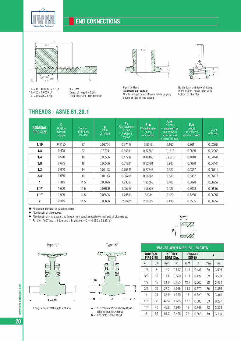
E0 = D -- (0.050D + 1.1)p* E1= E0 + 0.0625 L1 L2 = (0.80D = 6.8)p
p = PitchDepth of thread = 0.80pTotal Taper 3/4 -inch per Foot
Flush by HandTolerance on ProductOne turn large or small from notch on plug gauge or face of ring gauge.
Notch flush with face of fitting.If chamfered, notch flush withbottom of chamfer.
THREADS - ASME B1.20.1
NOMINAL PIPE SIZE
DOutsidediameterof pipe
Number
of threadsper inch
pPitch
of thread
E0Pitch diameter
at endof external
thread
E1Pitch diameter
at endof external
E1Normal
engagement byand betweenexternal and
internal threads
E1Length
of effectiveexternal thread
Heightof thread
1/16 0.3125 27 0.03704 0.27118 0.8118 0.160 0.2611 0,02963
1/8 0.405 27 0.3704 0.36351 0.37360 0.1615 0.2639 0,02963
1/4 0.540 18 0.05556 0.47739 0.49163 0.2278 0.4018 0,04444
3/8 0.675 18 0.05556 0.61201 0.62701 0.240 0.4078 0,04444
1/2 0.840 14 0.07143 0.75843 0.77843 0.320 0.5337 0,05714
3/4 1.050 14 0.07143 0.96768 0.98887 0.339 0.5457 0,05714
1 1.315 11.5 0.08696 1.23863 1.23863 0.400 0.6828 0,06957
1.1/4” 1.660 11.5 0.08696 1.55713 1.58338 0.420 0.7068 0,06957
1.1/2” 1.900 11.5 0.08696 1.79609 .82234 0.420 0.7235 0,06957
2 2.375 11.5 0.08696 2.2692 2.29627 0.436 0.7565 0,06957
Also pitch diameter at gauging notch.Also length of plug gauge.Also length of ring gauge, and length from gauging notch to small end of plug gauge.* For the 1/8-27 and 1/4-18 sizes... E1 approx. = D -- (0.05D + 0.827) p.
valves with nipples lenGhts
NOMINAL PIPE SIZE
SOCKET BORE DIA.
SOCKET DEPTH S
NPT DN mm in mm in mm in
1/4 8 14.2 0.557 11.1 0.437 89 3.503
3/8 10 17.6 0.690 11.1 0.437 89 3.503
1/2 15 21.8 0.855 12.7 0.500 88 3.464
3/4 20 27.2 1.065 14.5 0.570 86 3.385
1 25 33.9 1.330 16 0.629 85 3.346
1 1/4 32 42.57 1.675 17.5 0.688 83 3.267
1 1/2 40 48.8 1.915 19 0.748 82 3.228
2 50 61.2 2.406 22 0.866 79 3.110
Type “L”
Long Pattern Total length 400 mm. A = See relevant Product/Size/Class table within this catalog
S = See table Socket Weld
Type “S”
ww
w.ivm-om
bsaudi.com
21
PREPARATION FOR SHIPPING
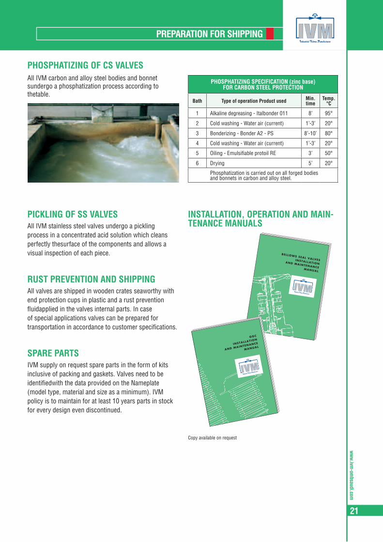
PHOSPHATIZING OF CS VALVES
PHOSPHATIZING SPECIFICATION (zinc base) FOR CARBON STEEL PROTECTION
Bath Type of operation Product used Min. time
Temp. °C
1 Alkaline degreasing - Italbonder 011 8’ 95°
2 Cold washing - Water air (current) 1’-3’ 20°
3 Bonderizing - Bonder A2 - PS 8’-10’ 80°
4 Cold washing - Water air (current) 1’-3’ 20°
5 Oiling - Emulsifiable protoil RE 3’ 50°
6 Drying 5’ 20°
Phosphatization is carried out on all forged bodies and bonnets in carbon and alloy steel.
All IVM carbon and alloy steel bodies and bonnet sundergo a phosphatization process according to thetable.
PICKLING OF SS VALVESAll IVM stainless steel valves undergo a pickling process in a concentrated acid solution which cleans perfectly thesurface of the components and allows a visual inspection of each piece.
RUST PREVENTION AND SHIPPINGAll valves are shipped in wooden crates seaworthy with end protection cups in plastic and a rust prevention fluidapplied in the valves internal parts. In case of special applications valves can be prepared for transportation in accordance to customer specifications.
SPARE PARTSIVM supply on request spare parts in the form of kits inclusive of packing and gaskets. Valves need to be identifiedwith the data provided on the Nameplate (model type, material and size as a minimum). IVM policy is to maintain for at least 10 years parts in stock for every design even discontinued.
Copy available on request
INSTALLATION, OPERATION AND MAIN-TENANCE MANUALS
BELLOWS SEAL VALVESINSTALLATIONAND MAINTENANCE MANUAL
GGC
INSTALLATION
AND MAINTENANCE
MANUAL

ww
w.iv
m-o
mbs
audi
.com
22
GATE

ww
w.ivm-om
bsaudi.com
23
MATERIALS FOR GATE VALVES
1 WHEELNUT Austentic ductile iron, 13Cr steel, or copper alloy having a melting point above 955°2 NAMEPLATE A corrosion resistent metal3 HANDWHEEL Malleable iron, carbon steel, or ductile iron4 YOKE NUT Carbon steel or similar material composition as the bonnet
5 GLAND NUTBolting materials of a type 300 or type 400 series stainless steel. Also, material at least equal to either ASTM A307-Grade B or EN 10269-C35E (1.1181) may be used for yoke bolting
6 GLAND FLANGE Steel7 GLAND STUD -8 GLAND Material with a melting point above 955° C
9 PACKING Non-asbestos material suitable for steam and petroleum fluids over a temperature range of - 29°C to 540°C and containing a corrosion inhibitor
10 BOLTS Unless other materials are agreed between the purchaser and manifacturer the bolting material shall be according with annex F
12 STEM -13 BONNET A forging or casting material as selected from ASME B 16.34, group 1 and Group 214 GASKET See 5.5.3
15 SEAT As in Table 11, except that when weld deposited facings are used, the base material shall have a corrosion resistance equal to or greater than that of the body material
17 WEDGE Steel or base material compatible with the pressure/temperature rating and least equal in corrosion resistance as the body material
18 BODY A forging or casting material as selected from ASME B 16.34, group 1 and Group 2
2
4
8
9
1310
6
5
14
181715
12
13
ww
w.iv
m-o
mbs
audi
.com
24
MATERIALS FOR GATE VALVES
A105/F6 A105/F6HFS LF2/304 F11/F6HFS F304/304 F316/316
Wheelnut Carbon Steel Carbon Steel Carbon Steel Carbon Steel Carbon Steel Carbon Steel
Nameplate Aluminium Aluminium Aluminium Aluminium Aluminium Aluminium
Handwheel Carbon Steel Carbon Steel Carbon Steel Carbon Steel Carbon Steel Carbon Steel
Yoke Nut 416 416 416 416 303 303
Gland Nut 2H 2H GR8 GR8 GR8 GR8
Gland Flange A105 A105 F6 F6 F304 F304
Gland Stud 410 410 B8 B8 B8 B8
Gland 316L 316L 316L 316L 316L 316L
Packing (*) Graphite Graphite Graphite Graphite Graphite Graphite
Bolts B7 B7 L7 B16 B8 B8
Stem 410 410 304 410 304 316
Bonnet A105 A105 LF2 F11 F304 F316
Gasket Sp. Wound Sp. Wound Sp. Wound Sp. Wound Sp. Wound Sp. Wound
Seat 410 410HF 304 410HF 304 316
Wedge F6 F6 F304 F6 F304 F316
Body A105 A105 LF2 F11 F304 F316
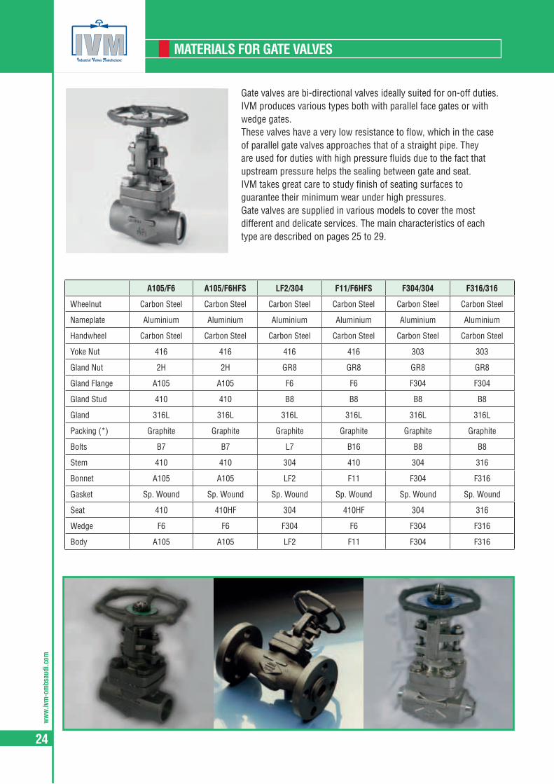
Gate valves are bi-directional valves ideally suited for on-off duties. IVM produces various types both with parallel face gates or with wedge gates.These valves have a very low resistance to flow, which in the case of parallel gate valves approaches that of a straight pipe. They are used for duties with high pressure fluids due to the fact that upstream pressure helps the sealing between gate and seat.IVM takes great care to study finish of seating surfaces to guarantee their minimum wear under high pressures.Gate valves are supplied in various models to cover the most different and delicate services. The main characteristics of each type are described on pages 25 to 29.
ww
w.ivm-om
bsaudi.com
25
GATE VALVES
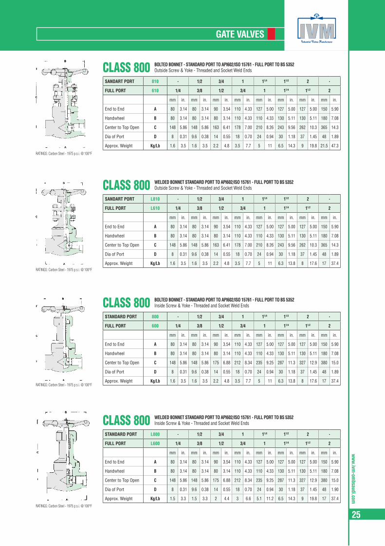
CLASS 800SANDART PORT 810 - 1/2 3/4 1 11/4 11/2 2 -
FULL PORT 610 1/4 3/8 1/2 3/4 1 11/4 11/2 2
mm in. mm in. mm in. mm in. mm in. mm in. mm in. mm in.
End to End A 80 3.14 80 3.14 90 3.54 110 4.33 127 5.00 127 5.00 127 5.00 150 5.90
Handwheel B 80 3.14 80 3.14 80 3.14 110 4.33 110 4.33 130 5.11 130 5.11 180 7.08
Center to Top Open C 148 5.86 148 5.86 163 6.41 178 7.00 210 8.26 243 9.56 262 10.3 365 14.3
Dia of Port D 8 0.31 9.6 0.38 14 0.55 18 0.70 24 0.94 30 1.18 37 1.45 48 1.89
Approx. Weight Kg/Lb 1.6 3.5 1.6 3.5 2.2 4.8 3.5 7.7 5 11 6.5 14.3 9 19.8 21.5 47.3
BOLTED BONNET - STANDARD PORT TO API602/ISO 15761 - FULL PORT TO BS 5352Outside Screw & Yoke - Threaded and Socket Weld Ends
CLASS 800SANDART PORT L810 - 1/2 3/4 1 11/4 11/2 2 -
FULL PORT L610 1/4 3/8 1/2 3/4 1 11/4 11/2 2
mm in. mm in. mm in. mm in. mm in. mm in. mm in. mm in.
End to End A 80 3.14 80 3.14 90 3.54 110 4.33 127 5.00 127 5.00 127 5.00 150 5.90
Handwheel B 80 3.14 80 3.14 80 3.14 110 4.33 110 4.33 130 5.11 130 5.11 180 7.08
Center to Top Open C 148 5.86 148 5.86 163 6.41 178 7.00 210 8.26 243 9.56 262 10.3 365 14.3
Dia of Port D 8 0.31 9.6 0.38 14 0.55 18 0.70 24 0.94 30 1.18 37 1.45 48 1.89
Approx. Weight Kg/Lb 1.6 3.5 1.6 3.5 2.2 4.8 3.5 7.7 5 11 6.3 13.8 8 17.6 17 37.4
WELDED BONNET STANDARD PORT TO API602/ISO 15761 - FULL PORT TO BS 5352Outside Screw & Yoke - Threaded and Socket Weld Ends
CLASS 800STANDARD PORT 800 - 1/2 3/4 1 11/4 11/2 2 -
FULL PORT 600 1/4 3/8 1/2 3/4 1 11/4 11/2 2
mm in. mm in. mm in. mm in. mm in. mm in. mm in. mm in.
End to End A 80 3.14 80 3.14 90 3.54 110 4.33 127 5.00 127 5.00 127 5.00 150 5.90
Handwheel B 80 3.14 80 3.14 80 3.14 110 4.33 110 4.33 130 5.11 130 5.11 180 7.08
Center to Top Open C 148 5.86 148 5.86 175 6.88 212 8.34 235 9.25 287 11.3 327 12.9 380 15.0
Dia of Port D 8 0.31 9.6 0.38 14 0.55 18 0.70 24 0.94 30 1.18 37 1.45 48 1.89
Approx. Weight Kg/Lb 1.6 3.5 1.6 3.5 2.2 4.8 3.5 7.7 5 11 6.3 13.8 8 17.6 17 37.4
BOLTED BONNET - STANDARD PORT TO API602/ISO 15761 - FULL PORT TO BS 5352Inside Screw & Yoke - Threaded and Socket Weld Ends
CLASS 800STANDARD PORT L800 - 1/2 3/4 1 11/4 11/2 2 -
FULL PORT L600 1/4 3/8 1/2 3/4 1 11/4 11/2 2
mm in. mm in. mm in. mm in. mm in. mm in. mm in. mm in.
End to End A 80 3.14 80 3.14 90 3.54 110 4.33 127 5.00 127 5.00 127 5.00 150 5.90
Handwheel B 80 3.14 80 3.14 80 3.14 110 4.33 110 4.33 130 5.11 130 5.11 180 7.08
Center to Top Open C 148 5.86 148 5.86 175 6.88 212 8.34 235 9.25 287 11.3 327 12.9 380 15.0
Dia of Port D 8 0.31 9.6 0.38 14 0.55 18 0.70 24 0.94 30 1.18 37 1.45 48 1.90
Approx. Weight Kg/Lb 1.5 3.3 1.5 3.3 2 4.4 3 6.6 5.1 11.2 6.5 14.3 9 19.8 17 37.4
WELDED BONNET STANDARD PORT TO API602/ISO 15761 - FULL PORT TO BS 5352Inside Screw & Yoke - Threaded and Socket Weld Ends
RATINGS: Carbon Steel - 1975 p.s.i. @ 100°F
RATINGS: Carbon Steel - 1975 p.s.i. @ 100°F
RATINGS: Carbon Steel - 1975 p.s.i. @ 100°F
RATINGS: Carbon Steel - 1975 p.s.i. @ 100°F
ww
w.iv
m-o
mbs
audi
.com
26
GATE VALVES
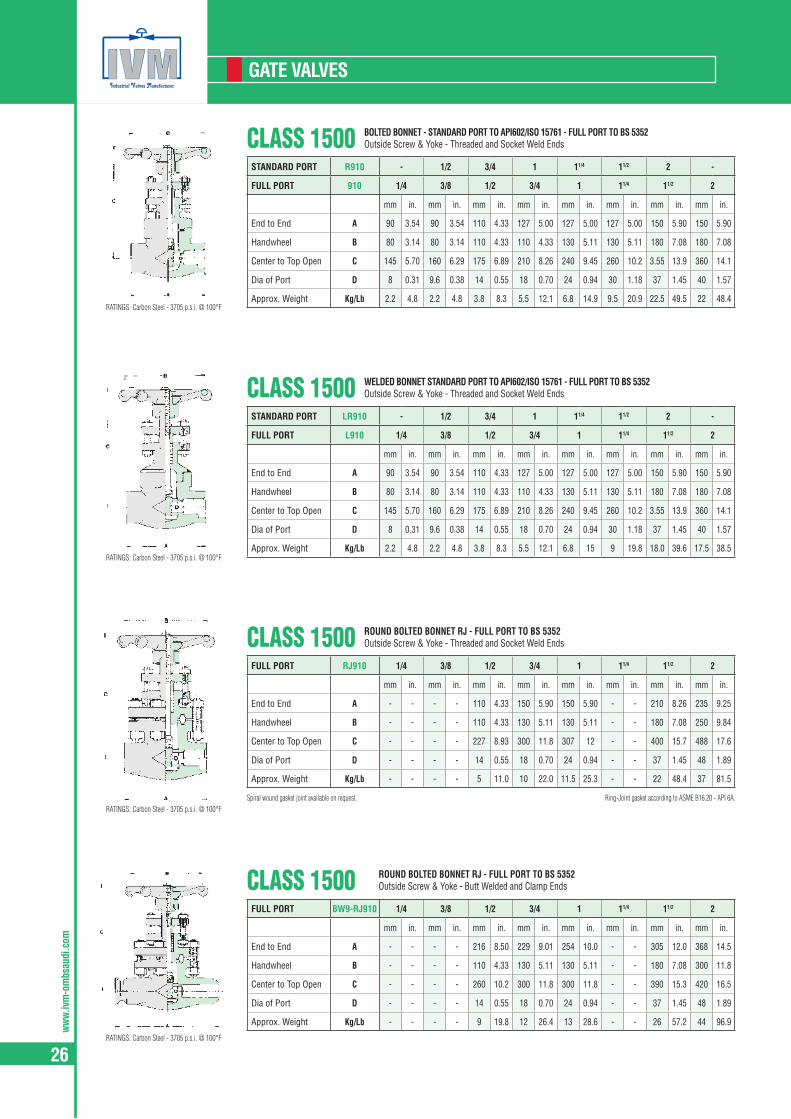
CLASS 1500STANDARD PORT R910 - 1/2 3/4 1 11/4 11/2 2 -
FULL PORT 910 1/4 3/8 1/2 3/4 1 11/4 11/2 2
mm in. mm in. mm in. mm in. mm in. mm in. mm in. mm in.
End to End A 90 3.54 90 3.54 110 4.33 127 5.00 127 5.00 127 5.00 150 5.90 150 5.90
Handwheel B 80 3.14 80 3.14 110 4.33 110 4.33 130 5.11 130 5.11 180 7.08 180 7.08
Center to Top Open C 145 5.70 160 6.29 175 6.89 210 8.26 240 9.45 260 10.2 3.55 13.9 360 14.1
Dia of Port D 8 0.31 9.6 0.38 14 0.55 18 0.70 24 0.94 30 1.18 37 1.45 40 1.57
Approx. Weight Kg/Lb 2.2 4.8 2.2 4.8 3.8 8.3 5.5 12.1 6.8 14.9 9.5 20.9 22.5 49.5 22 48.4
BOLTED BONNET - STANDARD PORT TO API602/ISO 15761 - FULL PORT TO BS 5352Outside Screw & Yoke - Threaded and Socket Weld Ends
CLASS 1500STANDARD PORT LR910 - 1/2 3/4 1 11/4 11/2 2 -
FULL PORT L910 1/4 3/8 1/2 3/4 1 11/4 11/2 2
mm in. mm in. mm in. mm in. mm in. mm in. mm in. mm in.
End to End A 90 3.54 90 3.54 110 4.33 127 5.00 127 5.00 127 5.00 150 5.90 150 5.90
Handwheel B 80 3.14 80 3.14 110 4.33 110 4.33 130 5.11 130 5.11 180 7.08 180 7.08
Center to Top Open C 145 5.70 160 6.29 175 6.89 210 8.26 240 9.45 260 10.2 3.55 13.9 360 14.1
Dia of Port D 8 0.31 9.6 0.38 14 0.55 18 0.70 24 0.94 30 1.18 37 1.45 40 1.57
Approx. Weight Kg/Lb 2.2 4.8 2.2 4.8 3.8 8.3 5.5 12.1 6.8 15 9 19.8 18.0 39.6 17.5 38.5
WELDED BONNET STANDARD PORT TO API602/ISO 15761 - FULL PORT TO BS 5352Outside Screw & Yoke - Threaded and Socket Weld Ends
CLASS 1500FULL PORT BW9-RJ910 1/4 3/8 1/2 3/4 1 11/4 11/2 2
mm in. mm in. mm in. mm in. mm in. mm in. mm in. mm in.
End to End A - - - - 216 8.50 229 9.01 254 10.0 - - 305 12.0 368 14.5
Handwheel B - - - - 110 4.33 130 5.11 130 5.11 - - 180 7.08 300 11.8
Center to Top Open C - - - - 260 10.2 300 11.8 300 11.8 - - 390 15.3 420 16.5
Dia of Port D - - - - 14 0.55 18 0.70 24 0.94 - - 37 1.45 48 1.89
Approx. Weight Kg/Lb - - - - 9 19.8 12 26.4 13 28.6 - - 26 57.2 44 96.9
ROUND BOLTED BONNET RJ - FULL PORT TO BS 5352Outside Screw & Yoke - Butt Welded and Clamp Ends
Spiral wound gasket joint available on request.
CLASS 1500FULL PORT RJ910 1/4 3/8 1/2 3/4 1 11/4 11/2 2
mm in. mm in. mm in. mm in. mm in. mm in. mm in. mm in.
End to End A - - - - 110 4.33 150 5.90 150 5.90 - - 210 8.26 235 9.25
Handwheel B - - - - 110 4.33 130 5.11 130 5.11 - - 180 7.08 250 9.84
Center to Top Open C - - - - 227 8.93 300 11.8 307 12 - - 400 15.7 488 17.6
Dia of Port D - - - - 14 0.55 18 0.70 24 0.94 - - 37 1.45 48 1.89
Approx. Weight Kg/Lb - - - - 5 11.0 10 22.0 11.5 25.3 - - 22 48.4 37 81.5
ROUND BOLTED BONNET RJ - FULL PORT TO BS 5352Outside Screw & Yoke - Threaded and Socket Weld Ends
Ring-Joint gasket according to ASME B16.20 - API 6A.
RATINGS: Carbon Steel - 3705 p.s.i. @ 100°F
RATINGS: Carbon Steel - 3705 p.s.i. @ 100°F
RATINGS: Carbon Steel - 3705 p.s.i. @ 100°F
RATINGS: Carbon Steel - 3705 p.s.i. @ 100°F

ww
w.ivm-om
bsaudi.com
27
GATE VALVES
CLASS 2500FULL PORT L2510 1/4 3/8 1/2 3/4 1 11/4 11/2 2
mm in. mm in. mm in. mm in. mm in. mm in. mm in. mm in.
End to End A - - - - 264 10.4 273 10.7 308 12.1 - - 384 15.1 451 17.7
Handwheel B - - - - 130 5.11 130 5.11 130 5.11 - - 300 11.8 300 11.8
Center to Top Open C - - - - 214 8.42 239 9.40 253 9.96 - - 425 16.7 430 16.9
Dia of Port D - - - - 14 0.55 18 0.70 24 0.94 - - 37 1.45 37 1.45
Approx. Weight Kg/Lb - - - - 5.8 12.7 7 15.4 10 22.0 - - 26 57.3 25.5 56.2
WELDED BONNET - FULL PORT - ASME B16.34Outside Screw & Yoke - Threaded and Socket Weld Ends
CLASS 2500FULL PORT RJ2510 1/4 3/8 1/2 3/4 1 11/4 11/2 2
mm in. mm in. mm in. mm in. mm in. mm in. mm in. mm in.
End to End A - - - - 150 5.90 150 5.90 210 8.26 - - 235 9.25 235 9.25
Handwheel B - - - - 130 5.11 130 5.11 250 9.84 - - 300 11.8 300 11.8
Center to Top Open C - - - - 293 11.5 300 11.8 390 15.3 - - 4.35 17.1 435 17.1
Dia of Port D - - - - 14 0.55 18 0.70 24 0.94 - - 37 1.45 37 1.45
Approx. Weight Kg/Lb - - - - 10 22.0 10.3 22.7 22.4 49.3 - - 38 83.7 38 83.7
ROUND BOLTED BONNET RJ - FULL PORT - ASME B16.34Outside Screw & Yoke - Threaded and Socket Weld Ends
Ring-Joint gasket according to ASME B16.20 - API 6A.
CLASS 2500FULL PORT BW25-RJ2510 1/4 3/8 1/2 3/4 1 11/4 11/2 2
mm in. mm in. mm in. mm in. mm in. mm in. mm in. mm in.
End to End A - - - - 264 10.4 273 10.7 308 12.1 - - 384 15.1 451 17.7
Handwheel B - - - - 130 5.11 130 5.11 250 9.84 - - 300 11.8 300 11.8
Center to Top Open C - - - - 304 11.9 315 12.4 368 14.5 - - 445 17.5 538 21.2
Dia of Port D - - - - 14 0.55 18 0.70 24 0.94 - - 37 1.45 37 1.45
Approx. Weight Kg/Lb - - - - 15 33.0 17 37.4 33 72.6 - - 51 112.3 75 165.1
ROUND BOLTED BONNET RJ - FULL PORT - ASME B16.34Outside Screw & Yoke - Butt Weld and Clamp Ends
Port dimension can change depending on schedule. (*) End to end dimension according to ANSI B16.10
Ring-Joint gasket according to ASME B16.20 - API 6A.
CLASS 2500FULL PORT BW25-L2510 1/4 3/8 1/2 3/4 1 11/4 11/2 2
mm in. mm in. mm in. mm in. mm in. mm in. mm in. mm in.
End to End A - - - - 264 10.4 273 10.7 308 12.1 - - 384 15.1 451 17.7
Handwheel B - - - - 130 5.11 130 5.11 250 9.84 - - 300 11.8 300 11.8
Center to Top Open C - - - - 304 11.9 315 12.4 368 14.5 - - 445 17.5 538 21.2
Dia of Port D - - - - 14 0.55 18 0.70 24 0.94 - - 37 1.45 37 1.45
Approx. Weight Kg/Lb - - - - 13 28.6 14 308 27 59.4 - - 41 90.3 62 136.5
WELDED BONNET - FULL PORT - ASME B16.34Outside Screw & Yoke - Butt Weld and Clamp Ends
Port dimension can change depending on schedule. (*) End to end dimension according to ANSI B16.10
RATINGS: Carbon Steel - 6170 p.s.i. @ 100°F
RATINGS: Carbon Steel - 6170 p.s.i. @ 100°F
RATINGS: Carbon Steel - 6170 p.s.i. @ 100°F
RATINGS: Carbon Steel - 6170 p.s.i. @ 100°F

ww
w.iv
m-o
mbs
audi
.com
28
GATE VALVES
CLASS 800-1500STANDARD PORT
CLASS 800 MLA-810 - 1/2 3/4 1 - 11/2 2 -
CLASS 1500 MLA-R910 - - 1/2 3/4 1 - 11/2 2
mm in. mm in. mm in. mm in. mm in. mm in. mm in. mm in.End to End A - - 148 5.82 153 6.02 182 7.16 216 8.50 216 8.50 264 10.4 264 10.4Center to Male End A1 - - 108 4.25 108 4.25 127 5.00 152 6.00 152 6.00 200 7.87 210 7.44Handwheel B - - 80 3.14 80 3.14 110 4.33 110 4.33 130 5.11 130 5.11 180 7.08Center to Top Open C - - 148 5.82 163 6.41 178 7.00 210 8.26 243 9.56 262 10.3 355 13.9Dia of Port
Class 800 D - - 9.6 0.38 14 0.55 18 0.70 - - 30 1.18 37 1.45 - -Class 1500 D - - - - 9.6 0.38 14 0.55 18 0.70 - - 30 1.18 37 1.45
Approx. Weight
Class 800 Kg/Lb - - 2.1 4.6 2.8 6.2 4.4 9.7 - - 8.1 17.8 10.5 23.2 - -Class 1500 Kg/Lb - - - - 3.1 6.8 4.8 10.6 7.5 16.5 - - 11.5 23.5 21.1 46.5
TAKE-OFF VALVE - WELDED BONNET - STANDARD PORT TO API602/ISO15761Outside Screw & Yoke - Threaded, Socket Weld and BW Ends
CLASS 800-1500STANDARD PORT
CLASS 800 MA-810 - 1/2 3/4 1 - 11/2 2 -
CLASS 1500 MA-R910 - - 1/2 3/4 1 - 11/2 2
mm in. mm in. mm in. mm in. mm in. mm in. mm in. mm in.End to End A - - 148 5.82 153 6.02 182 7.16 216 8.50 216 8.50 264 10.4 264 10.4Center to Male End A1 - - 108 4.25 108 4.25 127 5.00 152 6.00 152 6.00 200 7.87 210 7.44Handwheel B - - 80 3.14 80 3.14 110 4.33 110 4.33 130 5.11 130 5.11 180 7.08Center to Top Open C - - 148 5.82 163 6.41 178 7.00 210 8.26 243 9.56 262 10.3 355 13.9Dia of Port
Class 800 D - - 9.6 0.38 14 0.55 18 0.70 - - 30 1.18 37 1.45 - -Class 1500 D - - - - 9.6 0.38 14 0.55 18 0.70 - - 30 1.18 37 1.45
Approx. Weight
Class 800 Kg/Lb - - 2.1 4.6 2.8 6.2 4.4 9.7 - - 8.3 18.3 12 26.4 - -Class 1500 Kg/Lb - - - - 3.1 6.8 4.8 10.6 7.5 16.5 - - 12 26.4 22.1 48.7
TAKE-OFF VALVE - BOLTED BONNET - STANDARD PORT TO API602/ISO15761Outside Screw & Yoke - Threaded, Socket Weld and BW Ends
CLASS 800-1500STANDARD PORT
CLASS 800 MLW-810 - 1/2 3/4 1 - 11/2 2 -
CLASS 1500 MLW-R910 - - 1/2 3/4 1 - 11/2 2
mm in. mm in. mm in. mm in. mm in. mm in. mm in. mm in.End to End A - - 196 7.71 220 8.66 244 9.60 265 10.4 265 10.4 270 10.6 270 10.6Center to Male End A1 - - 156 6.14 175 6.88 189 7.44 201 7.91 201 7.91 206 8.11 220 6.50Handwheel B - - 80 3.14 80 3.14 110 4.33 110 4.33 130 5.11 130 5.11 180 7.08Center to Top Open C - - 148 5.82 163 6.41 178 7.00 210 8.26 243 9.56 262 10.3 355 13.9Dia of Port
Class 800 D - - 9.6 0.38 14 0.55 18 0.70 - - 30 1.18 37 1.45 - -Class 1500 D - - - - 9.6 0.38 14 0.55 18 0.70 - - 30 1.18 37 1.45
Approx. Weight
Class 800 Kg/Lb - - 3 6.6 3.2 7.0 5 11.0 - - 9.3 20.5 12.5 27.5 - -Class 1500 Kg/Lb - - - - 3.5 7.7 5.4 11.9 8.1 17.8 - - 13 28.6 23.1 50.9
REINFORCED EXTENDED BODY - WELDED BONNET - STANDARD PORT API602/ISO15761Outside Screw & Yoke - Threaded and Socket Weld Female Ends
Reinforced - Lip Class 800 & 1500
SIZE - 1/2 3/4 1 - 11/2 2 -H - - 18 0,70 23 0,91 28 1,10 - - 44 1,73 50 1,97 - -I - - 20,5 0,80 25,5 1,00 30,5 1,20 - - 47 1,85 53 2,08 - -G - - 4 0,15 4,5 0,17 5 0,19 - - 7 0,25 8 0,31 - -
Run Size Min. - 1 11/2 2 - 3 4 -
CLASS 800-1500STANDARD PORT
CLASS 800 MW-810 - 1/2 3/4 1 - 11/2 2 -
CLASS 1500 MW-R910 - - 1/2 3/4 1 - 11/2 2
mm in. mm in. mm in. mm in. mm in. mm in. mm in. mm in.End to End A - - 196 7.71 220 8.66 2.44 9.60 265 10.4 265 10.4 270 10.6 270 10.6Center to Male End A1 - - 156 6.14 175 6.88 189 7.44 201 7.91 201 7.91 206 8.11 220 6.50Handwheel B - - 80 3.14 80 3.14 110 4.33 110 4.33 130 5.11 130 5.11 180 7.08Center to Top Open C - - 148 5.82 163 6.41 178 7.00 210 8.26 243 9.56 262 10.3 355 13.9Dia of Port
Class 800 D - - 9.6 0.38 14 0.55 18 0.70 - - 30 1.18 37 1.45 - -Class 1500 D - - - - 9.6 0.38 14 0.55 18 0.70 - - 30 1.18 37 1.45
Approx. Weight
Class 800 Kg/Lb - - 3 6.6 3.2 7.0 5 11.0 - - 9.5 20.9 12.5 27.5 - -Class 1500 Kg/Lb - - - - 3.5 7.7 5.4 11.9 8.1 17.8 - - 13.5 29.7 24.1 53.0
REINFORCED EXTENDED BODY - BOLTED BONNET - STANDARD PORT API602/ISO15761Outside Screw & Yoke - Threaded and Socket Weld Female Ends
MWC
MWB
MW A
MC
MB
MA
MWD
MWW
MD
MW
RATINGS: Carbon Steel Class 800 - 1975 p.s.i. @ 100°FClass 1500 - 3705 p.s.i. @ 100°F
RATINGS: Carbon Steel Class 800 - 1975 p.s.i. @ 100°FClass 1500 - 3705 p.s.i. @ 100°F
RATINGS: Carbon Steel Class 800 - 1975 p.s.i. @ 100°FClass 1500 - 3705 p.s.i. @ 100°F
RATINGS: Carbon Steel Class 800 - 1975 p.s.i. @ 100°FClass 1500 - 3705 p.s.i. @ 100°F

ww
w.ivm-om
bsaudi.com
29
GATE VALVES
CLASS 2500FULL PORT F25-RJ2510 1/4 3/8 1/2 3/4 1 11/4 11/2 2
mm in. mm in. mm in. mm in. mm in. mm in. mm in. mm in.
End to End A - - - - 264 10.4 273 10.7 308 12.1 - - 384 15.1 451 17.7
Handwheel B - - - - 130 5.11 130 5.11 250 9.84 - - 300 11.8 300 11.8
Center to Top Open C - - - - 304 11.9 315 12.4 368 14.5 - - 445 17.5 538 21.2
Dia of Port D - - - - 14 0.55 18 0.70 24 0.94 - - 37 1.45 37 1.45
Approx. Weight Kg/Lb - - - - 19 41.8 21 46.2 40 88.1 - - 62 136.5 92 202.6
ROUND BOLTED BONNET RJ - FULL PORT - ASME B16.34Outside Screw & Yoke - Integral Flanged End according to ASME B16.5
End to end dimension according to ANSI B16.10
CLASS 1500FULL PORT F9-RJ910 1/4 3/8 1/2 3/4 1 11/4 11/2 2
mm in. mm in. mm in. mm in. mm in. mm in. mm in. mm in.
End to End A - - - - 216 8.50 229 9.01 254 10.0 - - 305 21.0 368 14.5
Handwheel B - - - - 110 4.33 130 5.11 130 5.11 - - 250 9.84 300 11.8
Center to Top Open C - - - - 260 10.2 300 11.8 300 11.8 - - 390 15.3 420 16.5
Dia of Port D - - - - 14 0.55 18 0.70 24 0.94 - - 37 1.45 48 1.89
Approx. Weight Kg/Lb - - - - 11 24.2 16 35.2 19 41.8 - - 35 77.1 59 130.0
ROUND BOLTED BONNET RJ - FULL PORT BS 5352Outside Screw & Yoke - Integral Flanged End according to ASME B16.5
End to end dimension according to ANSI B16.10Spiral wound gasket joint available on request
Ring-Joint gasket according to ASME B16.20 - API 6A.
CLASS 800-1500 BOLTED BONNET - STANDARD PORT TO API602/ISO15761Outside Screw & Yoke - Integral Flanged End according to ASME B16.5
End to end dimension according to ANSI B16.10Spiral wound gasket joint for #150-#300#150-#300 square bolted bonnet #600 round bolted bonnet
Ring-Joint gasket according to ASME B16.20 - API 6A.(*)End to end dimension according to ANSI B16.10
FULL PORT 1/4 3/8 1/2 3/4 1 11/4 11/2 2
mm in. mm in. mm in. mm in. mm in. mm in. mm in. mm in.Class 150 F1-610 A - - - - 108 4.25 117 4.64 127 5.00 - - 165 6.49 178 7.00Class 300 F3-610 A - - - - 140 5.51 152 6.02 165 6.49 - - 190 7.51 216 8.50Class 600 F6-RJ610 A - - - - 165 6.49 190 7.51 216 8.50 - - 241 9.48 292 11.5Handwheel B - - - - 110 4.33 110 4.33 130 5.11 - - 250 9.84 250 9.84
Center to Top Open
Class 150/300
C - - - - 170 6.69 195 7.67 210 8.26 - - 262 10.3 327 12.8
Class 600 C - - - - 244 9.60 268 10.5 310 12.2 - - 391 15.4 430 16.9Dia of Port D - - - - 14 0.55 18 0.70 24 0.94 - - 37 1.45 48 1.89
Approx. Weight
Class 150 Kg/Lb - - - - 3.6 7.9 4.8 10.5 6.5 14.3 - - 12 26.4 18 39.6Class 300 Kg/Lb - - - - 4.1 9.0 5.5 12.1 7.0 15.4 - - 13 29.6 19 41.8Class 600 Kg/Lb - - - - 6 13.2 11 24.2 13 28.6 - - 27 59.4 30 66.0
CLASS 150-300-600STANDARD PORT 1/4 3/8 1/2 3/4 1 11/4 11/2 2
mm in. mm in. mm in. mm in. mm in. mm in. mm in. mm in.Class 150 F1-810 A - - - - 108 4.25 117 4.64 127 5.00 - - 165 6.49 178 7.00Class 300 F3-810 A - - - - 140 5.51 152 6.02 165 6.49 - - 190 7.51 216 8.50Class 600 F6-810 A - - - - 165 6.49 190 7.51 216 8.50 - - 241 9.48 292 11.5Handwheel B - - - - 80 3.14 80 3.14 110 4.33 - - 130 5.11 130 5.11
Center to Top Open
Class 150/300
C - - - - 170 6.69 195 7.67 203 7.99 - - 243 9.56 262 10.3
Class 600 C - - - - 148 5.82 163 6.41 178 7.00 - - 243 9.56 262 10.3Dia of Port D - - - - 9.6 0.38 14 0.55 18 0.70 - - 30 1.18 37 1.45
Approx. Weight
Class 150 Kg/Lb - - - - 3.4 7.5 3.8 8.3 5.7 12.5 - - 9.7 21.4 13.2 29.1Class 300 Kg/Lb - - - - 3.9 8.6 5 11.0 6.2 13.6 - - 12 26.4 16.5 36.3Class 600 Kg/Lb - - - - 4 8.8 5.2 11.4 75 16.5 - - 15 33.0 20.5 45.1
BOLTED BONNET - STANDARD PORT TO API602/ISO15761Outside Screw & Yoke - Integral Flanged End according to ASME B16.5
End to end dimension according to ANSI B16.10(*) End to end dimension according to ANSI B16.10
RATINGS: Carbon Steel Class 150 - 285 p.s.i. @ 100°FClass 300 - 740 p.s.i. @ 100°FClass 600 - 1480 p.s.i. @ 100°F
RATINGS: Carbon Steel Class 150 - 285 p.s.i. @ 100°FClass 300 - 740 p.s.i. @ 100°FClass 600 - 1480 p.s.i. @ 100°F
RATINGS: Carbon Steel Class 150 - 285 p.s.i. @ 100°FClass 300 - 740 p.s.i. @ 100°FClass 600 - 1480 p.s.i. @ 100°F
RATINGS: Carbon Steel Class 150 - 285 p.s.i. @ 100°FClass 300 - 740 p.s.i. @ 100°FClass 600 - 1480 p.s.i. @ 100°F

ww
w.iv
m-o
mbs
audi
.com
30
GLOBE

ww
w.ivm-om
bsaudi.com
31
MATERIALS FOR GLOBE VALVES
2
12
4
8
9
10
7
6
5
14
181519
13
13
1 WHEELNUT Austentic ductile iron, 13Cr steel, or copper alloy having a melting point above 955°2 NAMEPLATE A corrosion resistent metal3 HANDWHEEL Malleable iron, carbon steel, or ductile iron4 YOKE NUT Carbon steel or similar material composition as the bonnet
5 GLAND NUT Bolting materials of a type 300 or type 400 series stainless steel. Also, material at least equal to either ASTM A307-Grade B or EN 10269-C35E (1.1181) may be used for yoke bolting
6 GLAND FLANGE Steel7 GLAND STUD -8 GLAND Material with a melting point above 955° C
9 PACKING Non-asbestos material suitable for steam and petroleum fluids over a temperature range of - 29°C to 540°C and containing a corrosion inhibitor
10 BOLTS Unless other materials are agreed between the purchaser and manifacturer the bolting material shall be according with annex F
12 STEM -13 BONNET A forging or casting material as selected from ASME B 16.34, group 1 and Group 214 GASKET See 5.5.3
15 SEAT As in Table 11, except that when weld deposited facings are used, the base material shall have a corrosion resistance equal to or greater than that of the body material
18 BODY A forging or casting material as selected from ASME B 16.34, group 1 and Group 2
19 DISC Steel or base material compatible with the pressure/temperature rating and least equal in corrosion resistance as the body material

ww
w.iv
m-o
mbs
audi
.com
32
MATERIALS FOR GLOBE VALVES
Globe valve are closing-down valves in which the closure memberis moved squarely on and off the seat. Inthis way the opening of the port is directly proportionalto the travel of the disc.This proportional relationship isideally suited for duties requiring regulation of flowrate. To have a further precision in regulation the discelement can be available in the parabolic, needle, v-port types. Furthermore the short travel of the discbetween the open and closed position makes these valves ideally suited for on-off duties when they must beopened and closed frequently.Globe valves are uni-directional valves and are installed so that fluid pressu-re is under the disc. They are supplied in variousmodels to cover the different servicesAmong these valves the Eco-L-Valve® combines the characteristics oftotal safety against leakages to the easy substitution ofthe most delicate components such as the bellows. Themain characteristics of each type are described onpages 33 to 37.
A105/F6 A105/F6HFS LF2/304 F11/F6HFS F304/304 F316/316
Wheelnut Carbon Steel Carbon Steel Carbon Steel Carbon Steel Carbon Steel Carbon Steel
Nameplate Aluminium Aluminium Aluminium Aluminium Aluminium Aluminium
Handwheel Carbon Steel Carbon Steel Carbon Steel Carbon Steel Carbon Steel Carbon Steel
Yoke Nut 416 416 416 416 303 303
Gland Nut 2H 2H GR8 GR8 GR8 GR8
Gland Flange A105 A105 F6 F6 F304 F304
Gland Stud 410 410 B8 B8 B8 B8
Gland 316L 316L 316L 316L 316L 316L
Packing (*) Graphite Graphite Graphite Graphite Graphite Graphite
Bolts B7 B7 L7 B16 B8 B8
Stem 410 410 304 410 304 316
Bonnet A105 A105 LF2 F11 F304 F316
Gasket Sp. Wound Sp. Wound Sp. Wound Sp. Wound Sp. Wound Sp. Wound
Seat 410 410HF 304 410HF 304 316
Wedge 410 410 304 410 304 316
Body A105 A105 LF2 F11 F304 F316

ww
w.ivm-om
bsaudi.com
33
GLOBE VALVES
CLASS 800STANDARD PORT 830 - 1/2 3/4 1 11/4 11/2 2 -
FULL PORT 630 1/4 3/8 1/2 3/4 1 11/4 11/2 2
mm in. mm in. mm in. mm in. mm in. mm in. mm in. mm in.
End to End A 80 3.14 80 3.14 90 3.54 110 4.33 127 5.00 155 6.10 170 6.69 210 8.26
Handwheel B 80 3.14 80 3.14 80 3.14 110 4.33 130 5.11 130 5.11 180 7.08 180 7.08
Center to Top Open C 148 5.82 148 5.82 165 6.49 180 7.08 213 8.38 248 9.76 257 10.1 370 14.5
Dia of Port D 7 0.28 9 0.35 13 0.51 17.5 0.69 23 0.89 29.5 1.16 35 1.37 45.5 1.79
Approx. Weight Kg/Lb 1.7 3.7 1.7 3.7 2.3 5.0 3.6 7.9 5.5 12.1 7.5 16.5 11.6 25.5 22.0 48.5
BOLTED BONNET - STANDARD PORT TO API602/ISO 15761 - FULL PORT TO BS 5352Outside Screw & Yoke - Threaded and Socket Weld Ends
CLASS 800STANDARD PORT L830 - 1/2 3/4 1 11/4 11/2 2 -
FULL PORT L630 1/4 3/8 1/2 3/4 1 11/4 11/2 2
mm in. mm in. mm in. mm in. mm in. mm in. mm in. mm in.
End to End A 80 3.14 80 3.14 90 3.54 110 4.33 127 5.00 155 6.10 170 6.69 210 8.26
Handwheel B 80 3.14 80 3.14 80 3.14 110 4.33 130 5.11 130 5.11 180 7.08 180 7.08
Center to Top Open C 148 5.82 148 5.82 165 6.49 180 7.08 213 8.38 248 9.76 257 10.1 370 14.5
Dia of Port D 7 0.28 9 0.35 13 0.51 17.5 0.69 23 0.89 29.5 1.16 35 1.37 45.5 1.79
Approx. Weight Kg/Lb 1.7 3.7 1.7 3.7 2.3 5.0 3.6 7.9 5.5 12.1 7.3 16 10.5 23.1 17.5 38.5
WELDED BONNET - STANDARD PORT TO API602/ISO 15761 - FULL PORT TO BS 5352Outside Screw & Yoke - Threaded and Socket Weld Ends
CLASS 800STANDARD PORT L820 - 1/2 3/4 1 11/4 11/2 2 -
FULL PORT 620 1/4 3/8 1/2 3/4 1 11/4 11/2 2
mm in. mm in. mm in. mm in. mm in. mm in. mm in. mm in.
End to End A 80 3.14 80 3.14 90 3.54 110 4.33 127 5.00 155 6.10 170 6.69 210 8.26
Handwheel B 80 3.14 80 3.14 80 3.14 110 4.33 130 5.11 130 5.11 130 5.11 180 7.08
Center to Top Open C 148 5.86 148 5.86 175 6.88 212 8.34 235 9.25 287 11.3 327 12.9 380 15.0
Dia of Port D 7 0.28 9 0.35 13 0.51 17.5 0.69 23 0.89 29.5 1.16 35 1.37 45.5 1.79
Approx. Weight Kg/Lb 1.5 3.3 1.5 3.3 2.0 4.4 3.7 8.1 5.5 12.1 7.3 16 10.5 23.1 17.5 38.5
WELDED BONNET - STANDARD PORT TO API602/ISO 15761 - FULL PORT TO BS 5352Inside Screw - Threaded and Socket Weld Ends
CLASS 1500STANDARD PORT R930 - 1/2 3/4 1 11/4 11/2 2 -
FULL PORT 930 1/4 3/8 1/2 3/4 1 11/4 11/2 2
mm in. mm in. mm in. mm in. mm in. mm in. mm in. mm in.
End to End A 90 3.54 90 3.54 110 4.33 127 5.00 155 6.10 170 6.69 210 8.26 210 8.26
Handwheel B 80 3.14 80 3.14 110 4.33 130 5.11 130 5.11 180 7.08 180 7.08 180 7.08
Center to Top Open C 160 6.29 160 6.29 175 6.88 210 8.26 244 9.60 250 9.84 370 14.5 375 14.7
Dia of Port D 7 0.28 9 0.35 13 0.51 17 0.67 21 0.83 28 1.10 33 1.30 37.5 1.48
Approx. Weight Kg/Lb 2.2 4.8 2.2 4.8 3.9 8.5 6 13.2 8 17.6 12 26.4 23.5 51.7 23 50.6
WELDED BONNET STANDARD PORT TO API602/ISO 15761 - FULL PORT TO BS 5352Outside Screw & Yoke - Threaded and Socket Weld Ends
RATINGS: Carbon Steel - 1975 p.s.i. @ 100°F
RATINGS: Carbon Steel - 1975 p.s.i. @ 100°F
RATINGS: Carbon Steel - 1975 p.s.i. @ 100°F
RATINGS: Carbon Steel - 1975 p.s.i. @ 100°F

ww
w.iv
m-o
mbs
audi
.com
34
GLOBE VALVES
CLASS 1500STANDARD PORT LR930 - 1/2 3/4 1 11/4 11/2 2 -
FULL PORT L930 1/4 3/8 1/2 3/4 1 11/4 11/2 2
mm in. mm in. mm in. mm in. mm in. mm in. mm in. mm in.
End to End A 90 3.54 90 3.54 110 4.33 127 5.00 155 6.10 170 6.69 210 8.26 210 8.26
Handwheel B 80 3.14 80 3.14 110 4.33 130 5.11 130 5.11 180 7.08 180 7.08 180 7.08
Center to Top Open C 160 6.29 160 6.29 175 6.88 210 8.26 244 9.60 250 9.84 370 14.5 375 14.7
Dia of Port D 7 0.28 9 0.35 13 0.51 17 0.67 21 0.83 28 1.10 33 1.30 37.5 1.48
Approx. Weight Kg/Lb 2.2 4.8 2.2 4.8 3.9 8.5 6 13.2 8 17.6 12 26.4 19 41.8 18.5 40.7
WELDED BONNET STANDARD PORT TO API602/ISO 15761 - FULL PORT TO BS 5352Outside Screw & Yoke - Threaded and Socket Weld Ends
CLASS 1500FULL PORT RJ930 1/4 3/8 1/2 3/4 1 11/4 11/2 2
mm in. mm in. mm in. mm in. mm in. mm in. mm in. mm in.
End to End A - - - - 110 4.33 150 5.90 150 5.90 - - 210 8.26 235 9.25
Handwheel B - - - - 110 4.33 130 5.11 130 5.11 - - 180 7.08 250 9.84
Center to Top Open C - - - - 235 9.25 265 10.4 310 12.2 - - 370 14.5 435 17.1
Dia of Port D - - - - 13 0.51 17 0.67 21 0.83 - - 33 1.30 37.5 1.48
Approx. Weight Kg/Lb - - - - 5.1 11.2 11 24.2 12.1 26.6 - - 22 48.4 37 81.5
ROUND BOLTED BONNET - FULL PORT BS 5352Outside Screw & Yoke - Threaded and Socket Weld Ends
CLASS 2500FULL PORT L2530 1/4 3/8 1/2 3/4 1 11/4 11/2 2
mm in. mm in. mm in. mm in. mm in. mm in. mm in. mm in.
End to End A - - - - 127 5.00 155 6.10 170 6.69 - - 235 9.25 235 9.25
Handwheel B - - - - 130 5.11 130 5.11 130 5.11 - - 300 11.8 300 11.8
Center to Top Open C - - - - 237 9.33 242 9.52 256 10.1 - - 430 16.9 435 17.1
Dia of Port D - - - - 13 0.51 17 0.67 21 0.83 - - 33 1.30 35 1.37
Approx. Weight Kg/Lb - - - - 6.5 14.3 8.5 18.7 12.5 27.5 - - 26 57.2 25.5 56.1
WELDED BONNET RJ - FULL PORT - ASME B16.34Outside Screw & Yoke - Socket and Butt Weld Ends
Ring-Joint gasket according to ASME B16.20 - API 6A.
CLASS 2500FULL PORT RJ250 1/4 3/8 1/2 3/4 1 11/4 11/2 2
mm in. mm in. mm in. mm in. mm in. mm in. mm in. mm in.
End to End A - - - - 150 5.90 150 5.90 210 8.26 - - 235 9.25 235 9.25
Handwheel B - - - - 130 5.11 130 5.11 250 9.84 - - 300 11.8 300 11.8
Center to Top Open C - - - - 265 10.4 254 10.4 360 14.1 - - 430 16.9 435 17.1
Dia of Port D - - - - 13 0.51 17 0.67 21 0.83 - - 33 1.30 35 1.37
Approx. Weight Kg/Lb - - - - 11 24.2 11.3 24.8 22.4 49.3 - - 38 83.7 38 83.7
ROUND BOLTED BONNET RJ - FULL PORT - ASME B16.34Outside Screw & Yoke - Socket and Butt Weld Ends
Spiral wound gasket joint available on request.
RATINGS: Carbon Steel - 3705 p.s.i. @ 100°F
RATINGS: Carbon Steel - 3705 p.s.i. @ 100°F
RATINGS: Carbon Steel - 3705 p.s.i. @ 100°F

ww
w.ivm-om
bsaudi.com
35
GLOBE VALVES
CLASS 4500FULL PORT L4530 1/4 3/8 1/2 3/4 1 11/4 11/2 2
mm in. mm in. mm in. mm in. mm in. mm in. mm in. mm in.
End to End A - - - - 155 6.10 170 6.69 210 8.26 - - 235 9.25 - -
Handwheel B - - - - 180 7.08 250 9.84 250 9.84 - - 300 11.8 - -
Center to Top Open C - - - - 240 9.44 250 11.2 350 13.7 - - 410 16.1 - -
Dia of Port D - - - - 11 0.43 11 0.43 14 0.55 - - 28 1.10 - -
Approx. Weight Kg/Lb - - - - 9 19.8 13 28.6 24.5 53.9 - - 28 61.7 - -
WELDED BONNET - FULL PORT - ASME B16.34Outside Screw & Yoke - Socket and Butt Weld Ends
2” on request
2” on request(*) End to end dimension according to ANSI B16.10
CLASS 4500FULL PORT RJ4530-BW 1/4 3/8 1/2 3/4 1 11/4 11/2 2
mm in. mm in. mm in. mm in. mm in. mm in. mm in. mm in.
End to End A - - - - 260 10.2 300 11.8 370 14.5 - - 370 14.5 - -
Handwheel B - - - - 180 7.08 250 9.84 300 11.8 - - 300 11.8 - -
Center to Top Open C - - - - 280 11.0 360 14.1 456 17.9 - - 466 18.3 - -
Dia of Port D - - - - 11 0.43 11 0.43 14 0.55 - - 28 1.10 - -
Approx. Weight Kg/Lb - - - - 18 39.6 34 74.9 50 110.1 - - 50 110.1 - -
ROUND BOLTED BONNET RJ - FULL PORT - ASME B16.34Outside Screw & Yoke - Clamp and Butt Weld Ends
2” on request(*) End to end dimension according to ANSI B16.10
CLASS 4500FULL PORT L4530-BW 1/4 3/8 1/2 3/4 1 11/4 11/2 2
mm in. mm in. mm in. mm in. mm in. mm in. mm in. mm in.
End to End A - - - - 260 10.2 300 11.8 370 14.5 - - 370 14.5 - -
Handwheel B - - - - 180 7.08 250 9.84 300 11.8 - - 300 11.8 - -
Center to Top Open C - - - - 280 11.0 360 14.1 456 17.9 - - 466 18.3 - -
Dia of Port D - - - - 11 0.43 11 0.43 14 0.55 - - 28 1.10 - -
Approx. Weight Kg/Lb - - - - 17 37.4 32 70.5 46 101.3 - - 46 101.3 - -
WELDED BONNET - FULL PORT - ASME B16.34Outside Screw & Yoke - Clamp and Butt Weld Ends
CLASS 4500FULL PORT RJ4530 - 1/2 3/4 1 11/4 11/2 2 -
mm in. mm in. mm in. mm in. mm in. mm in. mm in. mm in.
End to End A - - - - 210 8.26 210 8.26 235 9.25 - - 235 9.25 - -
Handwheel B - - - - 250 9.84 250 9.84 300 11.8 - - 300 11.8 - -
Center to Top Open C - - - - 345 13.5 350 13.7 420 16.5 - - 430 16.9 - -
Dia of Port D - - - - 9 0.35 11 0.43 14 0.55 - - 28 1.10 - -
Approx. Weight Kg/Lb - - - - 23 50.6 23 50.6 38.5 84.8 - - 38.5 84.8 - -
ROUND BOLTED BONNET RJ - FULL PORT - ASME B16.34Outside Screw & Yoke - Socket and Butt Weld Ends
2” on request Ring-Joint gasket according to ASME B16.20 - API 6A.RATINGS: Carbon Steel - 11110 p.s.i. @ 100°F
RATINGS: Carbon Steel - 11110 p.s.i. @ 100°F
RATINGS: Carbon Steel - 11110 p.s.i. @ 100°F
RATINGS: Carbon Steel - 11110 p.s.i. @ 100°F
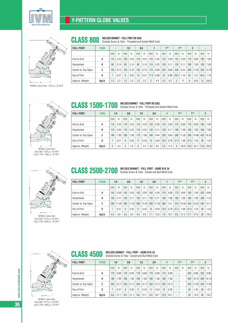
ww
w.iv
m-o
mbs
audi
.com
36
Y-PATTERN GLOBE VALVES
CLASS 800FULL PORT Y630 - 1/2 3/4 1 11/4 11/2 2 -
mm in. mm in. mm in. mm in. mm in. mm in. mm in. mm in.
End to End A 110 4.33 100 4.33 110 4.33 110 4.33 142 5.59 142 5.59 170 6.69 180 7.08
Handwheel B 80 3.14 80 3.14 80 3.14 110 4.33 130 5.11 130 5.11 180 7.08 180 7.08
Center to Top Open C 155 6.10 155 6.10 155 6.10 175 6.88 220 8.66 240 9.44 280 11.02 350 13.78
Dia of Port D 7 0.27 9 0.35 13 0.51 17.5 0.68 23 0.88 29.5 1.16 35 1.37 45.5 1.79
Approx. Weight Kg/Lb 1.5 3.3 1.5 3.3 1.5 3.3 2 4.4 4.2 9.2 5 11 9 19.8 13 28.6
WELDED BONNET - FULL PORT BS 5352Outside Screw & Yoke - Threaded and Socket Weld Ends
CLASS 1500-1700FULL PORT Y930 1/4 3/8 1/2 3/4 1 11/4 11/2 2
mm in. mm in. mm in. mm in. mm in. mm in. mm in. mm in.
End to End A 110 4.33 110 4.33 110 4.33 142 5.59 142 5.59 170 6.69 170 6.69 180 7.08
Handwheel B 110 4.33 110 4.33 110 4.33 130 5.11 130 5.11 180 7.08 180 7.08 180 7.08
Center to Top Open C 180 7.08 180 7.08 170 7.08 240 9.44 250 9.84 280 11.02 380 14.96 420 16.53
Dia of Port D 7 0.27 9 0.35 11 0.43 15 0.59 19.5 0.76 27.5 1.08 31.5 1.24 39 1.53
Approx. Weight Kg/Lb 2 4.4 2 4.4 2 4.4 4.2 9.2 5.2 11.4 9 20.9 10.5 23.1 13.5 29.8
WELDED BONNET - FULL PORT BS 5352Outside Screw & Yoke - Threaded and Socket Weld Ends
CLASS 2500-2700FULL PORT Y2530 1/4 3/8 1/2 3/4 1 11/4 11/2 2
mm in. mm in. mm in. mm in. mm in. mm in. mm in. mm in.
End to End A 142 5.59 142 5.59 142 5.59 142 5.59 170 6.69 170 6.69 180 7.08 225 8.86
Handwheel B 130 5.11 130 5.11 130 5.11 130 5.11 180 7.08 180 7.08 180 7.08 300 11.8
Center to Top Open C 280 11.02 280 11.02 280 11.02 280 11.02 360 14.1 370 14.56 420 16.53 540 21.2
Dia of Port D 7 0.27 9 0.35 11 0.43 15 0.59 19.5 0.76 27.5 1.08 31.5 1.24 39 1.53
Approx. Weight Kg/Lb 4.5 9.9 4.5 9.9 4.5 9.9 7.1 15.6 7.6 16.7 9.8 21.5 17.1 37.8 36 79.5
WELDED BONNET - FULL PORT - ASME B16.34Outside Screw & Yoke - Socket and Butt Weld Ends
CLASS 4500FULL PORT Y4530 1/4 3/8 1/2 3/4 1 11/4 11/2 2
mm in. mm in. mm in. mm in. mm in. mm in. mm in. mm in.
End to End A 170 6.69 170 6.69 170 6.69 170 6.69 170 6.69 - - 225 8.86 225 8.86
Handwheel B 180 7.08 180 7.08 180 7.08 180 7.08 180 7.08 - - 400 15.75 400 15.75
Center to Top Open C 350 13.77 350 13.77 350 13.77 350 13.77 350 13.77 - - 435 17.83 453 17.83
Dia of Port D 7 0.27 9 0.35 11 0.43 11 0.43 15 0.59 - - 26 1.02 28 1.01
Approx. Weight Kg/Lb 9.6 21.1 9.6 21.1 9.6 21.1 9.4 20.7 10.5 23.1 - - 34 75.0 36 79.5
WELDED BONNET - FULL PORT - ASME B16.34Outside Screw & Yoke - Socket and Butt Weld Ends
RATINGS: Carbon Steel - 1975 p.s.i. @ 100°F
RATINGS: Carbon Steel Class 1500 - 3705 p.s.i. @ 100°F Class* 1700 - 4198 p.s.i. @ 100°F
RATINGS: Carbon Steel Class 2500 - 6170 p.s.i. @ 100°F Class* 2700 - 6664 p.s.i. @ 100°F
RATINGS: Carbon Steel Class 2500 - 6170 p.s.i. @ 100°F Class* 2700 - 6664 p.s.i. @ 100°F

ww
w.ivm-om
bsaudi.com
37
GLOBE VALVES
CLASS 150-300-600 BOLTED BONNET - STANDARD PORT TO API602/ISO15761Outside Screw & Yoke - Integral Flanged End according to ASME B16.5
End to end dimension according to ANSI B16.10
STANDARD PORT 1/4 3/8 1/2 3/4 1 11/4 11/2 2
mm in. mm in. mm in. mm in. mm in. mm in. mm in. mm in.Class 150 F1-830 A - - - - 108 4.25 117 4.64 127 5.00 - - 165 6.49 178 7.00Class 300 F3-830 A - - - - 152 6.02 178 7.00 203 7.99 - - 229 9.01 267 10.5Class 600 F6-830 A - - - - 165 6.49 190 7.51 216 8.50 - - 241 9.48 292 11.5Handwheel B - - - - 80 3.14 80 3.14 110 4.33 - - 130 5.11 180 7.08
Center to Top Open
Class 150/300
C - - - - 148 5.82 165 6.49 180 7.08 - - 248 9.76 257 10.1
Class 600 C - - - - 170 6.69 197 7.75 205 8.07 - - 248 9.76 257 10.1Dia of Port D - - - - 9 0.35 13 0.51 17.5 0.69 - - 29.5 1.16 35 1.37
Approx. Weight
Class 150 Kg/Lb - - - - 3.4 7.5 4 8.8 5.7 12.5 - - 10 22.0 17.0 37.4Class 300 Kg/Lb - - - - 4 8.8 5 11.0 7.3 16.1 - - 14 30.8 20.5 45.1Class 600 Kg/Lb - - - - 4.5 9.9 5.5 12.1 7.6 16.7 - - 15 33.0 21 46.2
CLASS 150-300-600 BOLTED BONNET - STANDARD PORT - BS 5352Outside Screw & Yoke - Integral Flanged End according to ASME B16.5
End to end dimension according to ANSI B16.10Spiral wound gasket joint for #150
Ring-Joint gasket according to ASME B16.20 - API 6A.(*)End to end dimension BW on request Fig. N. BW 1-630/BW 6-630
FULL PORT 1/4 3/8 1/2 3/4 1 11/4 11/2 2
mm in. mm in. mm in. mm in. mm in. mm in. mm in. mm in.Class 150 F1-630 A - - - - 108 4.25 117 4.64 127 5.00 - - 165 6.49 203 7.99Class 300 F3-630 A - - - - 152 6.02 178 7.00 203 7.99 - - 229 9.01 267 10.5Class 600 F6-RJ630 A - - - - 165 6.49 190 7.51 216 8.50 - - 241 9.48 292 11.5Handwheel B - - - - 110 4.33 110 4.33 130 5.11 - - 250 9.84 250 9.84
Center to Top Open
Class 300/600
C - - - - 246 9.64 273 10.7 295 11.6 - - 410 16.1 440 17.3
Class 150 C - - - - 170 6.69 197 7.75 205 89.84 - - 285 11.02 320 12.6Dia of Port D - - - - 13 0.51 17.5 0.69 22.5 0.89 - - 35 1.37 45.5 1.79
Approx. Weight
Class 150 Kg/Lb - - - - 4.2 9.2 5.5 12.1 7.5 16.5 - - 13.5 29.7 21 46.2Class 300 Kg/Lb - - - - 5.8 12.8 10.8 23.8 12.8 28.2 - - 26.5 58.4 29 63.9Class 600 Kg/Lb - - - - 6 13.2 10 22.0 14.5 32.0 - - 27 59.4 30 66.0
CLASS 1500-2500 ROUND BOLTED BONNET RJ - FULL PORT - BS 5352 - ASME B16.34Outside Screw & Yoke - Integral Flanged End according to ASME B16.5
End to end dimension according to ANSI B16.10For class 1500 spiral wound gasket joint available on request
Ring-Joint gasket according to ASME B16.20 - API 6A.(*)End to end dimension BW on request Fig. N. BW 9-RJ930/BW 25-RJ2530
FULL PORT 1/4 3/8 1/2 3/4 1 11/4 11/2 2
mm in. mm in. mm in. mm in. mm in. mm in. mm in. mm in.Class 1500 F9-RJ930 A - - - - 216 8.50 229 9.01 254 10.0 - - 305 12.0 368 14.5Class 2500 F25-RJ2530 A - - - - 264 10.4 273 10.7 308 12.1 - - 384 15.1 451 17.7
HandwheelClass 1500 B - - - - 110 4.33 130 5.11 130 5.11 - - 250 9.84 300 11.8Class 2500 B - - - - 130 5.11 130 5.11 250 9.84 - - 300 11.8 300 11.8
Center to Top Open
Class 1500 C - - - - 260 10.2 300 11.8 300 11.8 - - 390 15.3 420 16.5Class 2500 C - - - - 332 13.0 332 13.0 370 14.5 - - 435 17.1 570 22.4
Dia of Port
Class 1500 D - - - - 13 0.51 17 0.67 21 0.83 - - 33 1.30 37.5 1.48Class 2500 D - - - - 11 0.43 17 0.67 21 0.83 - - 33 1.30 37.5 1.48
Approx. Weight
Class 1500 Kg/Lb - - - - 11 24.2 16 35.2 19.5 42.9 - - 34 74.8 61 134.3Class 2500 Kg/Lb - - - - 19.5 42.9 21.5 47.3 42 92.5 - - 65 143.2 95 209.2
CLASS 150-300-600FULL PORT 1/4 3/8 1/2 3/4 1 11/4 11/2 2
mm in. mm in. mm in. mm in. mm in. mm in. mm in. mm in.Class 150 1-Y630 A - - - - 108 4.25 117 4.64 127 5.00 - - 165 6.49 203 7.99Class 300 3-Y630 A - - - - 152 6.02 178 7.00 203 7.99 - - 299 9.01 267 10.5Class 600 6-Y630 A - - - - 165 6.49 190 7.51 216 8.50 - - 241 9.48 292 11.5Handwheel B - - - - 80 3.14 80 3.14 130 5.11 - - 180 7.08 180 7.08Center to Top Open C - - - - 155 6.10 175 6.88 220 8.66 - - 280 11.0 350 13.78Dia of Port D - - - - 13 0.51 17.5 0.68 22.5 0.88 - - 35 1.37 45.5 1.79
Approx. Weight
Class 150 Kg/Lb - - - - 3.2 7.4 4 8.8 7.2 15.8 - - 14.9 32.8 19 41.8Class 300 Kg/Lb - - - - 4.2 9.25 5.7 12.5 10.7 23.5 - - 16.4 36.1 21 46.2Class 600 Kg/Lb - - - - 4.7 10.3 6 13.2 11.7 25.7 - - 17.4 38.3 23 50.6
WELDED BONNET - FULL PORT - ISO15761 BS 5352Outside Screw & Yoke - Flanged End according to ASME B16.5
End to end dimension according to ANSI B16.10
RATINGS: Carbon Steel Class 150 - 285 p.s.i. @ 100°F Class 300 - 740 p.s.i. @ 100°F Class 600 - 1480 p.s.i. @ 100°F
RATINGS: Carbon Steel Class 150 - 285 p.s.i. @ 100°F Class 300 - 740 p.s.i. @ 100°F Class 600 - 1480 p.s.i. @ 100°F
RATINGS: Carbon Steel Class 150 - 285 p.s.i. @ 100°F Class 300 - 740 p.s.i. @ 100°F Class 600 - 1480 p.s.i. @ 100°F
RATINGS: Carbon Steel Class 150 - 285 p.s.i. @ 100°F Class 300 - 740 p.s.i. @ 100°F Class 600 - 1480 p.s.i. @ 100°F
ww
w.iv
m-o
mbs
audi
.com
38
CHECK
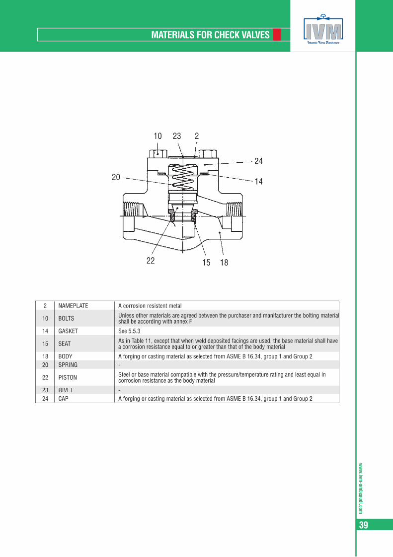
ww
w.ivm-om
bsaudi.com
39
MATERIALS FOR CHECK VALVES
24
1420
10 23 2
181522
2 NAMEPLATE A corrosion resistent metal
10 BOLTS Unless other materials are agreed between the purchaser and manifacturer the bolting material shall be according with annex F
14 GASKET See 5.5.3
15 SEAT As in Table 11, except that when weld deposited facings are used, the base material shall have a corrosion resistance equal to or greater than that of the body material
18 BODY A forging or casting material as selected from ASME B 16.34, group 1 and Group 220 SPRING -
22 PISTON Steel or base material compatible with the pressure/temperature rating and least equal in corrosion resistance as the body material
23 RIVET -24 CAP A forging or casting material as selected from ASME B 16.34, group 1 and Group 2
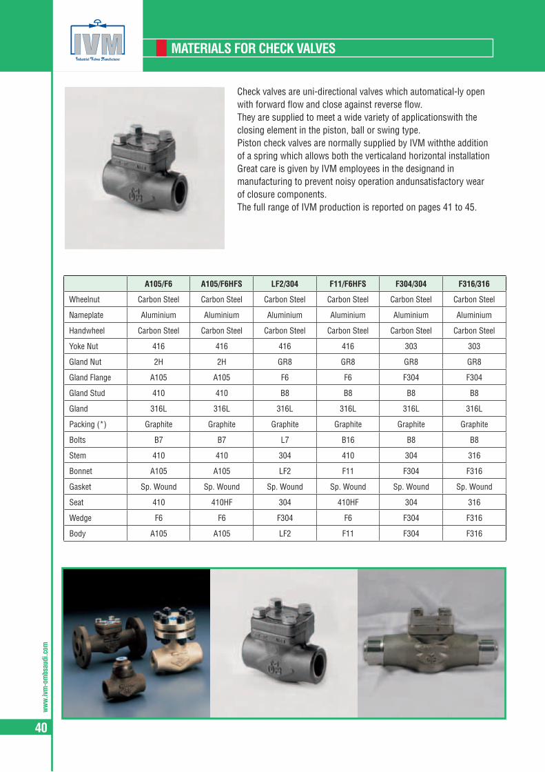
ww
w.iv
m-o
mbs
audi
.com
40
MATERIALS FOR CHECK VALVES
Check valves are uni-directional valves which automatical-ly open with forward flow and close against reverse flow.They are supplied to meet a wide variety of applicationswith the closing element in the piston, ball or swing type.Piston check valves are normally supplied by IVM withthe addition of a spring which allows both the verticaland horizontal installationGreat care is given by IVM employees in the designand in manufacturing to prevent noisy operation andunsatisfactory wear of closure components.The full range of IVM production is reported on pages 41 to 45.
A105/F6 A105/F6HFS LF2/304 F11/F6HFS F304/304 F316/316
Wheelnut Carbon Steel Carbon Steel Carbon Steel Carbon Steel Carbon Steel Carbon Steel
Nameplate Aluminium Aluminium Aluminium Aluminium Aluminium Aluminium
Handwheel Carbon Steel Carbon Steel Carbon Steel Carbon Steel Carbon Steel Carbon Steel
Yoke Nut 416 416 416 416 303 303
Gland Nut 2H 2H GR8 GR8 GR8 GR8
Gland Flange A105 A105 F6 F6 F304 F304
Gland Stud 410 410 B8 B8 B8 B8
Gland 316L 316L 316L 316L 316L 316L
Packing (*) Graphite Graphite Graphite Graphite Graphite Graphite
Bolts B7 B7 L7 B16 B8 B8
Stem 410 410 304 410 304 316
Bonnet A105 A105 LF2 F11 F304 F316
Gasket Sp. Wound Sp. Wound Sp. Wound Sp. Wound Sp. Wound Sp. Wound
Seat 410 410HF 304 410HF 304 316
Wedge F6 F6 F304 F6 F304 F316
Body A105 A105 LF2 F11 F304 F316

ww
w.ivm-om
bsaudi.com
41
CHECK VALVES
CLASS 800STANDARD PORT
PISTON 840 BALL 850 SWING 860
- 1/2 3/4 1 11/4 11/2 2 -
FULL PORTPISTON 640 BALL 650 SWING 660
1/4 3/8 1/2 3/4 1 11/4 11/2 2
mm in. mm in. mm in. mm in. mm in. mm in. mm in. mm in.
End to End
Piston - Ball
A 80 3.14 80 3.14 90 3.54 110 4.33 127 5.00 155 6.10 170 6.69 210 8.26
Swing A 80 3.14 80 3.14 90 3.54 110 4.33 127 5.00 127 5.00 127 5.00 210 8.26Center to Top Open C 53 2.08 53 2.08 60 2.36 73 2.87 80 3.14 98 3.85 118 4.64 150 5.90
Dia of Port
Piston - Ball
D 7 0.28 9 0.35 13 0.51 17.5 0.69 23 0.88 29.5 1.16 35 1.38 45.5 1.79
Swing D 8 0.31 9.6 0.38 14 0.55 18 0.70 24 0.94 30 1.18 37 1.45 48 1.89
Approx. Weight
Piston - Ball
Kg/Lb 1.3 2.8 1.3 2.8 1.4 3.0 2.4 5.2 4.0 8.8 7.4 16.2 8 17.6 18 39.6
Swing Kg/Lb 1.3 2.8 1.3 2.8 1.4 3.0 2.4 5.2 4.0 8.8 5.5 12.1 6.5 14.3 17.5 38.5
PISTON, BALL AND SWING TYPE - STANDARD PORT TO API602/ISO 15761 - FULL PORT TO BS 5352Bolted Cover - Threaded and Socket Weld Ends
CLASS 1500STANDARD PORT
PISTON R940 BALL R950 SWING R960
- 1/2 3/4 1 11/4 11/2 2 -
FULL PORTPISTON 940 BALL 950 SWING 960
1/4 3/8 1/2 3/4 1 11/4 11/2 2
mm in. mm in. mm in. mm in. mm in. mm in. mm in. mm in.
End to End
Piston - Ball
A 90 3.54 90 3.54 110 4.33 127 5.00 155 6.10 170 6.99 210 8.26 210 8.26
Swing A 90 3.54 90 3.54 110 4.33 127 5.00 127 5.00 127 5.00 210 8.26 210 2.26Center to Top Open C 60 2.36 60 2.36 73 2.87 80 3.14 98 3.85 118 4.64 150 5.90 150 5.90
Dia of Port
Piston - Ball
D 7 0.28 9 0.35 13 0.51 17.5 0.69 21 0.83 28 1.10 33 1.30 37.5 1.48
Swing D 8 0.31 9.6 0.38 14 0.55 18 0.70 24 0.94 30 1.18 37 1.45 40 1.57
Approx. Weight
Piston - Ball
Kg/Lb 1.5 3.3 1.5 3.3 2.8 6.1 4.6 10.1 7.4 16.2 9 19.8 19.5 49.9 19 41.8
Swing Kg/Lb 1.6 3.5 1.5 3.3 2.4 5.2 4 8.8 6 13.2 9.5 20.9 19 41.8 18.5 40.7
PISTON, BALL AND SWING TYPE - STANDARD PORT TO API602/ISO 15761- FULL PORT TO BS 5352Bolted Cover - Threaded and Socket Weld Ends
CLASS 800STANDARD PORT PISTON L840
BALL L850 - 1/2 3/4 1 11/4 11/2 2 -
FULL PORT PISTON L640 BALL L650 1/4 3/8 1/2 3/4 1 11/4 11/2 2
mm in. mm in. mm in. mm in. mm in. mm in. mm in. mm in.End to End A 80 3.14 80 3.14 90 3.54 110 4.33 127 5.00 155 6.10 170 6.69 210 8.26Center to Top Open C 53 2.08 53 2.08 60 2.36 73 2.87 80 3.14 98 3.85 110 4.33 150 5.90Dia of Port D 7 0.28 9 0.35 13 0.51 17.5 0.69 23 0.88 29.5 1.16 35 1.38 45.5 1.79Approx. Weight Kg/Lb 1.3 2.8 1.3 2.8 1.4 3.0 2.4 5.2 4.0 8.8 7.4 16.2 8 17.6 17 37.4
PISTON AND BALL TYPE - STANDARD PORT TO API602/ISO 15761 - FULL PORT TO BS 5352Welded Cover - Threaded and Socket Weld Ends
CLASS 1500STANDARD PORT PISTON LR940
BALL LR950 - 1/2 3/4 1 11/4 11/2 2 -
FULL PORT PISTON L940 BALL L950 1/4 3/8 1/2 3/4 1 11/4 11/2 2
mm in. mm in. mm in. mm in. mm in. mm in. mm in. mm in.End to End A 90 3.54 90 3.54 110 4.33 127 5.00 155 6.10 170 6.69 210 826 210 8.26Center to Top Open C 60 2.36 60 2.36 73 2.87 80 3.14 98 3.85 110 4.33 150 5.90 150 5.90Dia of Port D 7 0.28 9 0.35 13 0.51 17 0.67 21 0.83 28 1.10 33 1.30 37.5 1.47Approx. Weight Kg/Lb 1.5 3.3 1.5 3.3 2.8 6.1 4.6 10.1 7.4 16.3 9 19.8 15 33.0 14.5 31.9
PISTON AND BALL TYPE - STANDARD PORT TO API602/ISO 15761 - FULL PORT TO BS 5352Welded Cover - Threaded and Socket Weld Ends
RATINGS: Carbon Steel - 1975 p.s.i. @ 100°F
RATINGS: Carbon Steel - 1975 p.s.i. @ 100°F
RATINGS: Carbon Steel - 1975 p.s.i. @ 100°F
RATINGS: Carbon Steel - 1975 p.s.i. @ 100°F
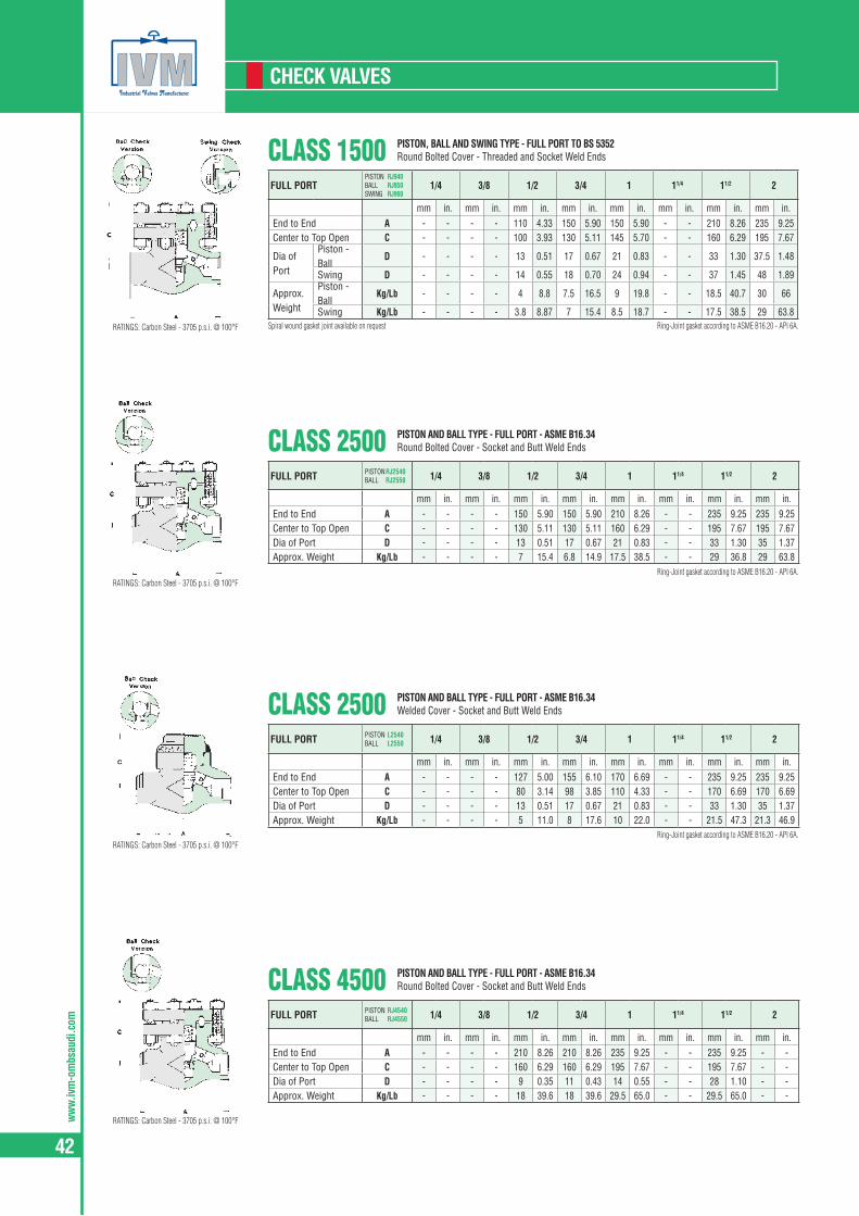
ww
w.iv
m-o
mbs
audi
.com
42
CHECK VALVES
CLASS 2500FULL PORT PISTON L2540
BALL L2550 1/4 3/8 1/2 3/4 1 11/4 11/2 2
mm in. mm in. mm in. mm in. mm in. mm in. mm in. mm in.End to End A - - - - 127 5.00 155 6.10 170 6.69 - - 235 9.25 235 9.25Center to Top Open C - - - - 80 3.14 98 3.85 110 4.33 - - 170 6.69 170 6.69Dia of Port D - - - - 13 0.51 17 0.67 21 0.83 - - 33 1.30 35 1.37Approx. Weight Kg/Lb - - - - 5 11.0 8 17.6 10 22.0 - - 21.5 47.3 21.3 46.9
PISTON AND BALL TYPE - FULL PORT - ASME B16.34Welded Cover - Socket and Butt Weld Ends
CLASS 1500FULL PORT
PISTON RJ940 BALL RJ950 SWING RJ960
1/4 3/8 1/2 3/4 1 11/4 11/2 2
mm in. mm in. mm in. mm in. mm in. mm in. mm in. mm in.End to End A - - - - 110 4.33 150 5.90 150 5.90 - - 210 8.26 235 9.25Center to Top Open C - - - - 100 3.93 130 5.11 145 5.70 - - 160 6.29 195 7.67
Dia of Port
Piston - Ball
D - - - - 13 0.51 17 0.67 21 0.83 - - 33 1.30 37.5 1.48
Swing D - - - - 14 0.55 18 0.70 24 0.94 - - 37 1.45 48 1.89
Approx. Weight
Piston - Ball
Kg/Lb - - - - 4 8.8 7.5 16.5 9 19.8 - - 18.5 40.7 30 66
Swing Kg/Lb - - - - 3.8 8.87 7 15.4 8.5 18.7 - - 17.5 38.5 29 63.8
PISTON, BALL AND SWING TYPE - FULL PORT TO BS 5352Round Bolted Cover - Threaded and Socket Weld Ends
Spiral wound gasket joint available on request Ring-Joint gasket according to ASME B16.20 - API 6A.
CLASS 2500FULL PORT PISTON RJ2540
BALL RJ2550 1/4 3/8 1/2 3/4 1 11/4 11/2 2
mm in. mm in. mm in. mm in. mm in. mm in. mm in. mm in.End to End A - - - - 150 5.90 150 5.90 210 8.26 - - 235 9.25 235 9.25Center to Top Open C - - - - 130 5.11 130 5.11 160 6.29 - - 195 7.67 195 7.67Dia of Port D - - - - 13 0.51 17 0.67 21 0.83 - - 33 1.30 35 1.37Approx. Weight Kg/Lb - - - - 7 15.4 6.8 14.9 17.5 38.5 - - 29 36.8 29 63.8
PISTON AND BALL TYPE - FULL PORT - ASME B16.34Round Bolted Cover - Socket and Butt Weld Ends
Ring-Joint gasket according to ASME B16.20 - API 6A.
CLASS 4500FULL PORT PISTON RJ4540
BALL RJ4550 1/4 3/8 1/2 3/4 1 11/4 11/2 2
mm in. mm in. mm in. mm in. mm in. mm in. mm in. mm in.End to End A - - - - 210 8.26 210 8.26 235 9.25 - - 235 9.25 - -Center to Top Open C - - - - 160 6.29 160 6.29 195 7.67 - - 195 7.67 - -Dia of Port D - - - - 9 0.35 11 0.43 14 0.55 - - 28 1.10 - -Approx. Weight Kg/Lb - - - - 18 39.6 18 39.6 29.5 65.0 - - 29.5 65.0 - -
PISTON AND BALL TYPE - FULL PORT - ASME B16.34Round Bolted Cover - Socket and Butt Weld Ends
Ring-Joint gasket according to ASME B16.20 - API 6A.
RATINGS: Carbon Steel - 3705 p.s.i. @ 100°F
RATINGS: Carbon Steel - 3705 p.s.i. @ 100°F
RATINGS: Carbon Steel - 3705 p.s.i. @ 100°F
RATINGS: Carbon Steel - 3705 p.s.i. @ 100°F
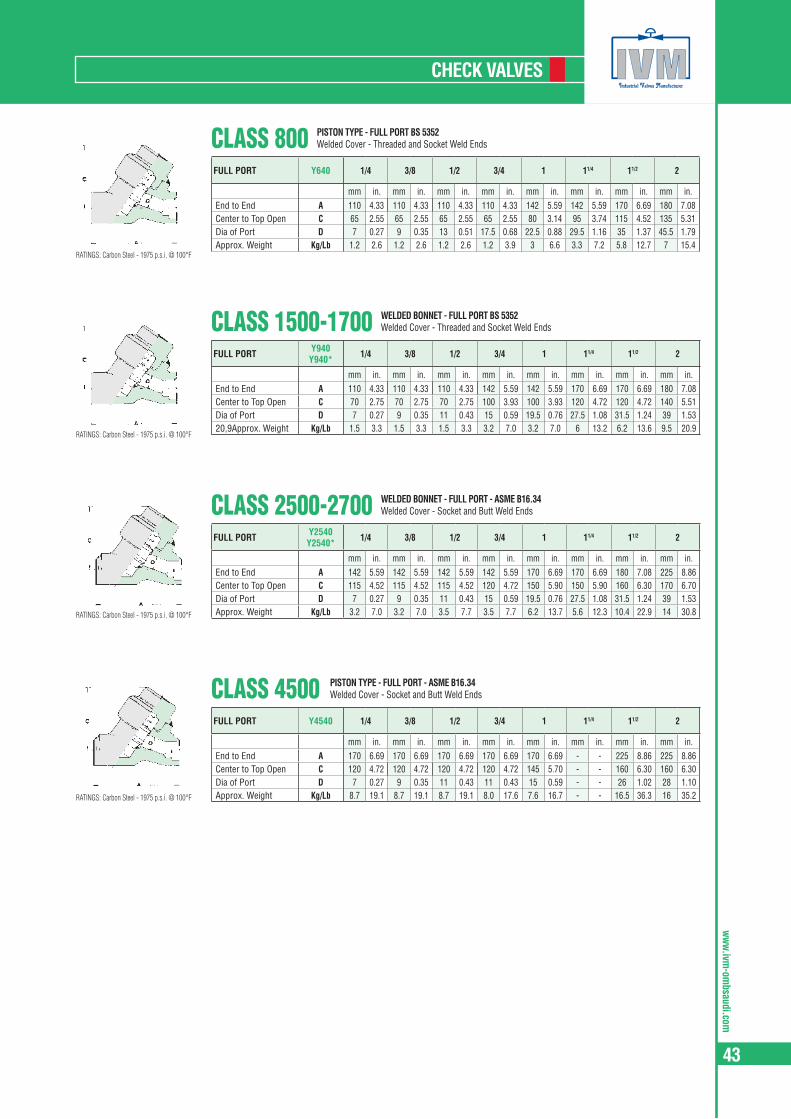
ww
w.ivm-om
bsaudi.com
43
CHECK VALVES
CLASS 1500-1700FULL PORT Y940
Y940* 1/4 3/8 1/2 3/4 1 11/4 11/2 2
mm in. mm in. mm in. mm in. mm in. mm in. mm in. mm in.End to End A 110 4.33 110 4.33 110 4.33 142 5.59 142 5.59 170 6.69 170 6.69 180 7.08Center to Top Open C 70 2.75 70 2.75 70 2.75 100 3.93 100 3.93 120 4.72 120 4.72 140 5.51Dia of Port D 7 0.27 9 0.35 11 0.43 15 0.59 19.5 0.76 27.5 1.08 31.5 1.24 39 1.5320,9Approx. Weight Kg/Lb 1.5 3.3 1.5 3.3 1.5 3.3 3.2 7.0 3.2 7.0 6 13.2 6.2 13.6 9.5 20.9
WELDED BONNET - FULL PORT BS 5352Welded Cover - Threaded and Socket Weld Ends
CLASS 2500-2700FULL PORT Y2540
Y2540* 1/4 3/8 1/2 3/4 1 11/4 11/2 2
mm in. mm in. mm in. mm in. mm in. mm in. mm in. mm in.End to End A 142 5.59 142 5.59 142 5.59 142 5.59 170 6.69 170 6.69 180 7.08 225 8.86Center to Top Open C 115 4.52 115 4.52 115 4.52 120 4.72 150 5.90 150 5.90 160 6.30 170 6.70Dia of Port D 7 0.27 9 0.35 11 0.43 15 0.59 19.5 0.76 27.5 1.08 31.5 1.24 39 1.53Approx. Weight Kg/Lb 3.2 7.0 3.2 7.0 3.5 7.7 3.5 7.7 6.2 13.7 5.6 12.3 10.4 22.9 14 30.8
WELDED BONNET - FULL PORT - ASME B16.34Welded Cover - Socket and Butt Weld Ends
CLASS 4500FULL PORT Y4540 1/4 3/8 1/2 3/4 1 11/4 11/2 2
mm in. mm in. mm in. mm in. mm in. mm in. mm in. mm in.End to End A 170 6.69 170 6.69 170 6.69 170 6.69 170 6.69 - - 225 8.86 225 8.86Center to Top Open C 120 4.72 120 4.72 120 4.72 120 4.72 145 5.70 - - 160 6.30 160 6.30Dia of Port D 7 0.27 9 0.35 11 0.43 11 0.43 15 0.59 - - 26 1.02 28 1.10Approx. Weight Kg/Lb 8.7 19.1 8.7 19.1 8.7 19.1 8.0 17.6 7.6 16.7 - - 16.5 36.3 16 35.2
PISTON TYPE - FULL PORT - ASME B16.34Welded Cover - Socket and Butt Weld Ends
CLASS 800FULL PORT Y640 1/4 3/8 1/2 3/4 1 11/4 11/2 2
mm in. mm in. mm in. mm in. mm in. mm in. mm in. mm in.End to End A 110 4.33 110 4.33 110 4.33 110 4.33 142 5.59 142 5.59 170 6.69 180 7.08Center to Top Open C 65 2.55 65 2.55 65 2.55 65 2.55 80 3.14 95 3.74 115 4.52 135 5.31Dia of Port D 7 0.27 9 0.35 13 0.51 17.5 0.68 22.5 0.88 29.5 1.16 35 1.37 45.5 1.79Approx. Weight Kg/Lb 1.2 2.6 1.2 2.6 1.2 2.6 1.2 3.9 3 6.6 3.3 7.2 5.8 12.7 7 15.4
PISTON TYPE - FULL PORT BS 5352Welded Cover - Threaded and Socket Weld Ends
RATINGS: Carbon Steel - 1975 p.s.i. @ 100°F
RATINGS: Carbon Steel - 1975 p.s.i. @ 100°F
RATINGS: Carbon Steel - 1975 p.s.i. @ 100°F
RATINGS: Carbon Steel - 1975 p.s.i. @ 100°F
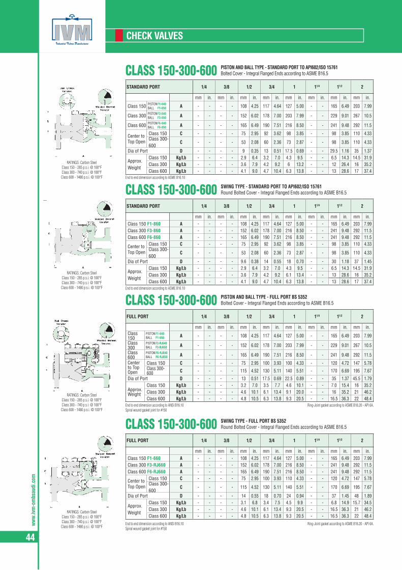
ww
w.iv
m-o
mbs
audi
.com
44
CHECK VALVES
CLASS 150-300-600STANDARD PORT 1/4 3/8 1/2 3/4 1 11/4 11/2 2
mm in. mm in. mm in. mm in. mm in. mm in. mm in. mm in.
Class 150 PISTON F1-840 BALL F1-850 A - - - - 108 4.25 117 4.64 127 5.00 - - 165 6.49 203 7.99
Class 300 PISTON F3-840 BALL F3-850 A - - - - 152 6.02 178 7.00 203 7.99 - - 229 9.01 267 10.5
Class 600 PISTON F6-840 BALL F6-850 A - - - - 165 6.49 190 7.51 216 8.50 - - 241 9.48 292 11.5
Center to Top Open
Class 150 C - - - - 75 2.95 92 3.62 98 3.85 - - 98 3.85 110 4.33Class 300-600
C - - - - 53 2.08 60 2.36 73 2.87 - - 98 3.85 110 4.33
Dia of Port D - - - - 9 0.35 13 0.51 17.5 0.69 - - 29.5 1.16 35 1.37
Approx. Weight
Class 150 Kg/Lb - - - - 2.9 6.4 3.2 7.0 4.3 9.5 - - 6.5 14.3 14.5 31.9Class 300 Kg/Lb - - - - 3.6 7.9 4.2 9.2 6 13.2 - - 12 26.4 16 35.2Class 600 Kg/Lb - - - - 4.1 9.0 4.7 10.4 6.3 13.8 - - 13 28.6 17 37.4
PISTON AND BALL TYPE - STANDARD PORT TO API602/ISO 15761Bolted Cover - Integral Flanged Ends according to ASME B16.5
End to end dimension according to ASME B16.10
CLASS 150-300-600STANDARD PORT 1/4 3/8 1/2 3/4 1 11/4 11/2 2
mm in. mm in. mm in. mm in. mm in. mm in. mm in. mm in.Class 150 F1-860 A - - - - 108 4.25 117 4.64 127 5.00 - - 165 6.49 203 7.99Class 300 F3-860 A - - - - 152 6.02 178 7.00 216 8.50 - - 241 9.48 292 11.5Class 600 F6-860 A - - - - 165 6.49 190 7.51 216 8.50 - - 241 9.48 292 11.5
Center to Top Open
Class 150 C - - - - 75 2.95 92 3.62 98 3.85 - - 98 3.85 110 4.33Class 300-600
C - - - - 53 2.08 60 2.36 73 2.87 - - 98 3.85 110 4.33
Dia of Port D - - - - 9.6 0.38 14 0.55 18 0.70 - - 30 1.18 37 1.45
Approx. Weight
Class 150 Kg/Lb - - - - 2.9 6.4 3.2 7.0 4.3 9.5 - - 6.5 14.3 14.5 31.9Class 300 Kg/Lb - - - - 3.6 7.9 4.2 9.2 6.1 13.4 - - 13 28.6 16 35.2Class 600 Kg/Lb - - - - 4.1 9.0 4.7 10.4 6.3 13.8 - - 13 28.6 17 37.4
SWING TYPE - STANDARD PORT TO API602/ISO 15761Round Bolted Cover - Integral Flanged Ends according to ASME B16.5
End to end dimension according to ASME B16.10
CLASS 150-300-600FULL PORT 1/4 3/8 1/2 3/4 1 11/4 11/2 2
mm in. mm in. mm in. mm in. mm in. mm in. mm in. mm in.Class 150
PISTON F1-640 BALL F1-650 A - - - - 108 4.25 117 4.64 127 5.00 - - 165 6.49 203 7.99
Class 300
PISTON F3-RJ640 BALL F3-RJ650 A - - - - 152 6.02 178 7.00 203 7.99 - - 229 9.01 267 10.5
Class 600
PISTON F6-RJ840 BALL F6-RJ850 A - - - - 165 6.49 190 7.51 216 8.50 - - 241 9.48 292 11.5
Center to Top Open
Class 150 C - - - - 75 2.95 100 3.93 100 4.33 - - 120 4.72 147 5.78Class 300-600 C - - - - 115 4.52 130 5.11 140 5.51 - - 170 6.69 195 7.67
Dia of Port D - - - - 13 0.51 17.5 0.69 22.5 0.89 - - 35 1.37 45.5 1.79
Approx. Weight
Class 150 Kg/Lb - - - - 3.2 7.0 3.5 7.7 4.6 10.1 - - 7.0 15.4 16 35.2Class 300 Kg/Lb - - - - 4.6 10.1 6.1 13.4 9.1 20.0 - - 16 35.2 21 46.2Class 600 Kg/Lb - - - - 4.8 10.5 6.3 13.8 9.3 20.5 - - 16.5 36.3 22 48.4
PISTON AND BALL TYPE - FULL PORT BS 5352Bolted Cover - Integral Flanged Ends according to ASME B16.5
End to end dimension according to ANSI B16.10Spiral wound gasket joint for #150
Ring-Joint gasket according to ASME B16.20 - API 6A.
CLASS 150-300-600FULL PORT 1/4 3/8 1/2 3/4 1 11/4 11/2 2
mm in. mm in. mm in. mm in. mm in. mm in. mm in. mm in.Class 150 F1-660 A - - - - 108 4.25 117 4.64 127 5.00 - - 165 6.49 203 7.99Class 300 F3-RJ660 A - - - - 152 6.02 178 7.00 216 8.50 - - 241 9.48 292 11.5Class 600 F6-RJ660 A - - - - 165 6.49 190 7.51 216 8.50 - - 241 9.48 292 11.5
Center to Top Open
Class 150 C - - - - 75 2.95 100 3.93 110 4.33 - - 120 4.72 147 5.78Class 300-600
C - - - - 115 4.52 130 5.11 140 5.51 - - 170 6.69 195 7.67
Dia of Port D - - - - 14 0.55 18 0.70 24 0.94 - - 37 1.45 48 1.89
Approx. Weight
Class 150 Kg/Lb - - - - 3.1 6.8 3.4 7.5 4.5 9.9 - - 6.8 14.9 15.7 34.5Class 300 Kg/Lb - - - - 4.6 10.1 6.1 13.4 9.3 20.5 - - 16.5 36.3 21 46.2Class 600 Kg/Lb - - - - 4.8 10.5 6.3 13.8 9.3 20.5 - - 16.5 36.3 22 48.4
SWING TYPE - FULL PORT BS 5352Round Bolted Cover - Integral Flanged Ends according to ASME B16.5
End to end dimension according to ANSI B16.10Spiral wound gasket joint for #150
Ring-Joint gasket according to ASME B16.20 - API 6A.
RATINGS: Carbon Steel Class 150 - 285 p.s.i. @ 100°F Class 300 - 740 p.s.i. @ 100°F Class 600 - 1480 p.s.i. @ 100°F
RATINGS: Carbon Steel Class 150 - 285 p.s.i. @ 100°F Class 300 - 740 p.s.i. @ 100°F Class 600 - 1480 p.s.i. @ 100°F
RATINGS: Carbon Steel Class 150 - 285 p.s.i. @ 100°F Class 300 - 740 p.s.i. @ 100°F Class 600 - 1480 p.s.i. @ 100°F
RATINGS: Carbon Steel Class 150 - 285 p.s.i. @ 100°F Class 300 - 740 p.s.i. @ 100°F Class 600 - 1480 p.s.i. @ 100°F

ww
w.ivm-om
bsaudi.com
45
CHECK VALVES
CLASS 1500FULL PORT
PISTON F9-RJ940 BALL F9-RJ950 SWING F9-RJ960
1/4 3/8 1/2 3/4 1 11/4 11/2 2
mm in. mm in. mm in. mm in. mm in. mm in. mm in. mm in.End to End A - - - - 216 8,50 229 9,01 254 10,0 - - 305 12,0 368 14,5Center to Top Open C - - - - 130 5,11 140 5,51 155 6,10 - - 170 6,69 195 7,67
Dia of Port
Piston - Ball
D - - - - 13 0,51 17 0,67 21 0,83 - - 33 1,30 37,5 1,48
Swing D - - - - 14 0,55 18 0,70 24 0,94 - - 37 1,45 48 1,89
Approx. Weight
Piston - Ball
Kg/Lb - - - - 8 17,6 14 30,8 17 37,5 - - 28 61,6 37 81,4
Swing Kg/Lb - - - - 7,8 17,1 13,8 30,4 16,5 36,3 - - 27 59,5 35 77,1
PISTON, BALL AND SWING TYPE - FULL PORT TO BS 5352Round Bolted Cover - Integral Flanged Ends according to ASME B16.5
End to end dimension according to ANSI B16.10Spiral wound gasket joint for #150
Ring-Joint gasket according to ASME B16.20 - API 6A.
CLASS 2500FULL PORT PISTON F25-RJ2540
BALL F25-RJ2550 1/4 3/8 1/2 3/4 1 11/4 11/2 2
mm in. mm in. mm in. mm in. mm in. mm in. mm in. mm in.End to End A - - - - 264 10.4 273 10.7 308 12.1 - - 384 15.1 451 17.7Center to Top Open C - - - - 155 6.10 155 6.10 170 6.69 - - 245 9.64 260 10.23Dia of Port D - - - - 11 0.43 17 0.67 21 0.83 - - 33 1.30 37.5 1.48Approx. Weight Kg/Lb - - - - 17 37.5 21 46.2 28 61.6 - - 58 127.7 85 187.2
PISTON AND BALL TYPE - FULL PORT - ASME B16.34Round Bolted Cover - Integral Flanged Ends according to ASME B16.5
End to end dimension according to ANSI B16.10 Ring-Joint gasket according to ASME B16.20 - API 6A.
CLASS 1500FULL PORT 9-Y940 1/4 3/8 1/2 3/4 1 11/4 11/2 2
mm in. mm in. mm in. mm in. mm in. mm in. mm in. mm in.End to End A - - - - 216 8.50 229 9.01 154 10.0 - - 305 12.0 368 14.5Center to Top Open C - - - - 70 2.75 100 3.93 100 3.93 - - 120 4.72 140 5.51Dia of Port D - - - - 11 0.43 15 0.59 19.5 0.76 - - 31.5 1.24 39 1.53Approx. Weight Kg/Lb - - - - 7.4 16.3 9.5 21.0 10.6 23.3 - - 18.2 40.0 33.5 73.8
PISTON TYPE - STANDARD PORT TO API602/ISO 15761Welded Cover - Flanged Ends according to ASME B16.5
End to end dimension according to ANSI B16.10
CLASS 2500FULL PORT 25-Y2540 1/4 3/8 1/2 3/4 1 11/4 11/2 2
mm in. mm in. mm in. mm in. mm in. mm in. mm in. mm in.End to End A - - - - 264 10.4 273 10.7 308 12.1 - - 384 15.1 451 17.7Center to Top Open C - - - - 115 4.52 120 4.72 150 5.90 - - 165 6.49 180 7.08Dia of Port D - - - - 11 0.43 15 0.59 19.5 0.76 - - 31.5 1.24 39 1.53Approx. Weight Kg/Lb - - - - 12 26.4 14.2 31.3 20.2 44.5 - - 37.4 82.3 65.6 144.5
PISTON TYPE - FULL PORT - ASME B16.34Welded Cover - Flanged Ends according to ASME B16.5
End to end dimension according to ANSI B16.10
RATINGS: Carbon Steel - 3075 p.s.i. @ 100°F
RATINGS: Carbon Steel - 3075 p.s.i. @ 100°F
RATINGS: Carbon Steel - 3075 p.s.i. @ 100°F
RATINGS: Carbon Steel - 3075 p.s.i. @ 100°F
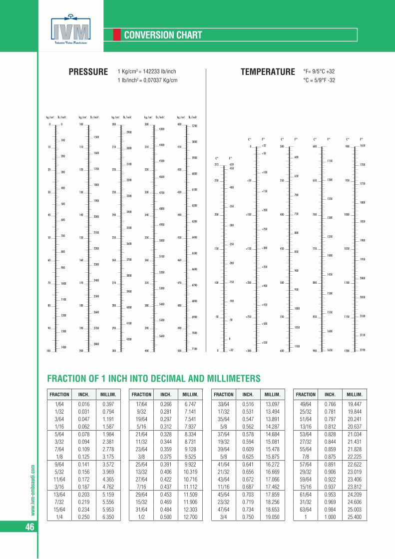
ww
w.iv
m-o
mbs
audi
.com
46
CONVERSION CHART
-400
-350
-300
-250
-200
-150
-100
-50
0
-250
-200
-150
-100
-50
PRESSURE TEMPERATURE1 Kg/cm2 = 142233 lb/inch
1 lb/inch2 = 0,07037 Kg/cm
°F= 9/5°C +32
°C = 5/9°F -32
kg./cm2. lb./inch2.
0
100
200
300
400
500
600
700
800
900
1000
1100
1200
1300
1400
0
10
20
30
40
50
60
70
80
90
100
kg./cm2. lb./inch2.
1500
1600
1700
1800
1900
2000
2100
2200
2300
2400
2500
2600
2700
2800
100
110
120
130
140
150
160
170
180
190
200
C°
kg./cm2. lb./inch2.
2900
3000
3100
3200
3300
3400
3500
3600
3700
3800
3900
4000
4100
4200
200
210
220
230
240
250
260
270
280
290
300
kg./cm2. lb./inch2.
4300
4400
4500
4600
4700
4800
4900
5000
5100
5200
5300
5400
5500
5600
300
310
320
330
340
350
360
370
380
390
400
kg./cm2. lb./inch2.
5700
5800
5900
6000
6100
6200
6300
6400
6500
6600
6700
6800
6900
7000
7100
400
410
420
430
440
450
460
470
480
490
500
F°
-459-273
+32 21900
-450
+50
+100
+150
+200
+250
+300
+350
+400
+450
+500
+550
0
+50
+100
+150
+200
+250
+300
C° F°
+32 1650
600
650
700
750
800
850
900
950
1000
1050
1100
300
350
400
450
500
550
600
C° F°
1150
1200
1250
1300
1350
1400
1450
1500
1550
1600
1650
600
650
700
750
800
850
900
C° F°
1700
1750
1800
1850
1900
1950
2000
2050
2100
2150
900
950
1000
1050
1100
1150
1200
C° F°
FRACTION INCH. MILLIM.
1/64 0.016 0.3971/32 0.031 0.7943/64 0.047 1.1911/16 0.062 1.5875/64 0.078 1.9843/32 0.094 2.3817/64 0.109 2.7781/8 0.125 3.175
9/64 0.141 3.5725/32 0.156 3.969
11/64 0.172 4.3653/16 0.187 4.762
13/64 0.203 5.1597/32 0.219 5.556
15/64 0.234 5.9531/4 0.250 6.350
FRACTION INCH. MILLIM.
17/64 0.266 6.7479/32 0.281 7.141
19/64 0.297 7.5415/16 0.312 7.937
21/64 0.328 8.33411/32 0.344 8.73123/64 0.359 9.1283/8 0.375 9.525
25/64 0.391 9.92213/32 0.406 10.31927/64 0.422 10.7167/16 0.437 11.112
29/64 0.453 11.50915/32 0.469 11.90631/64 0.484 12.3031/2 0.500 12.700
FRACTION INCH. MILLIM.
33/64 0.516 13.09717/32 0.531 13.49435/64 0.547 13.8915/8 0.562 14.287
37/64 0.578 14.68419/32 0.594 15.08139/64 0.609 15.4785/8 0.625 15.875
41/64 0.641 16.27221/32 0.656 16.66943/64 0.672 17.06611/16 0.687 17.46245/64 0.703 17.85923/32 0.719 18.25647/64 0.734 18.6533/4 0.750 19.050
FRACTION INCH. MILLIM.
49/64 0.766 19.44725/32 0.781 19.84451/64 0.797 20.24113/16 0.812 20.63753/64 0.828 21.03427/32 0.844 21.43155/64 0.859 21.8287/8 0.875 22.225
57/64 0.891 22.62229/32 0.906 23.01959/64 0.922 23.40615/16 0.937 23.81261/64 0.953 24.20931/32 0.969 24.60663/64 0.984 25.003
1 1.000 25.400
FRACTION OF 1 INCH INTO DECIMAL AND MILLIMETERS

ww
w.ivm-om
bsaudi.com
47
CONVERSION CHART
INCH 0 1 2 3 4 5 6 7 8 9 10 11 12 13 14
0 0.000 25.400 50.800 76.200 101.60 127.00 152.40 177.80 203.20 228.60 254.00 279.40 304.80 330.20 355.601/64 0.397 25.797 51.197 76.597 102.00 127.40 152.80 178.20 203.60 229.00 254.40 279.80 305.20 330.60 356.00
1/32 0.794 26.194 51.594 76.994 102.39 127.79 153.19 178.59 203.99 229.39 254.79 280.19 305.59 330.99 356.393/64 1.191 26.591 51.991 77.391 102.79 128.19 153.59 178.99 204.39 229.79 255.19 280.59 305.99 331.39 356.79
1/16 1.587 26.987 52.387 77.787 103.19 128.59 153.99 179.39 204.79 230.19 255.59 280.99 306.39 331.79 357.195/64 1.984 27.384 52.784 78.184 103.58 128.98 154.38 179.78 205.18 230.58 255.98 281.38 306.78 332.18 357.58
3/32 2.381 27.781 53.181 78.581 103.98 129.38 154.78 180.18 205.58 230.98 256.38 281.78 307.18 332.58 357.987/64 2.778 28.178 53.578 78.978 104.38 129.78 155.18 180.58 205.98 231.38 256.78 282.18 307.58 332.98 358.38
1/8 3.175 28.575 53.975 79.375 104.77 130.17 155.57 180.97 206.37 231.77 257.17 282.57 309.97 333.37 358.779/64 3.572 28.972 54.372 79.772 105.17 130.57 155.97 181.37 206.77 232.17 257.57 282.97 308.37 333.77 359.17
5/32 3.969 29.369 54.769 80.169 105.57 130.97 156.37 181.77 207.17 232.57 257.97 283.37 308.77 334.17 359.5711/64 4.366 29.766 55.166 80.566 105.97 131.37 156.77 182.17 207.57 232.97 258.37 283.77 309.17 334.57 359.97
3/16 4.762 30.162 55.562 80.962 106.38 131.76 157.16 182.56 207.96 233.36 258.76 285.16 309.56 334.96 360.3813/64 5.159 30.559 55.959 81.359 106.76 132.16 157.56 182.96 208.36 233.76 259.16 284.56 309.96 335.36 360.76
7/32 5.556 30.956 56.356 81.756 107.16 132.56 157.96 183.36 208.76 234.16 259.56 284.96 310.36 335.76 361.1615/64 5.953 31.353 56.753 82.153 107.55 132.95 158.35 183.75 209.15 234.55 259.95 285.35 310.75 336.15 361.55
1/4 6.350 31.750 57.150 82.550 107.95 133.35 158.75 184.15 209.55 234.95 260.35 285.75 311.15 336.55 361.9517/64 6.747 32.147 57.547 82.947 108.35 133.75 159.15 184.55 209.95 235.35 260.75 286.15 311.55 336.95 362.35
9/32 7.144 32.544 57.944 83.344 108.74 134.14 159.54 184.94 210.34 235.74 261.14 286.54 311.94 337.34 362.7419/64 7.541 32.941 58.341 83.741 109.14 134.54 159.94 185.34 210.74 236.14 261.54 286.94 312.34 337.74 363.14
5/16 7.937 33.337 58.737 84.137 109.54 134.94 160.34 185.74 211.14 236.54 261.94 287.34 312.74 338.14 363.5421/64 8.334 33.734 59.134 84.534 109.93 135.33 160.73 186.13 211.53 236.93 262.33 287.73 313.13 338.53 363.93
11/32 8.731 34.131 59.531 84.931 110.33 135.73 161.13 186.53 211.93 237.33 262.73 288.13 313.53 338.93 364.3323/64 9.128 34.528 59.928 85.328 110.73 136.13 161.53 186.93 212.33 237.73 263.13 288.53 313.93 339.33 364.73
3/8 9.525 34.925 60.325 85.725 111.12 136.52 161.92 187.32 212.72 238.12 263.52 288.92 314.32 339.72 365.1225/64 9.922 35.322 60.722 86.122 111.52 136.92 162.32 187.72 213.12 238.52 263.92 289.32 314.72 340.12 365.52
13/32 10.319 35.719 61.119 86.519 111.92 137.32 162.72 188.12 213.52 238.92 264.32 289.72 315.12 340.52 365.9227/64 10.716 36.116 61.516 86.916 112.32 137.72 163.12 188.52 213.92 239.32 264.72 290.12 315.52 340.92 366.32
7/16 11.112 36.512 61.912 87.312 112.71 138.11 163.51 188.91 214.31 239.71 265.11 290.51 315.91 341.31 366.7129/64 11.509 36.909 62.309 87.709 113.11 138.51 163.91 189.31 214.71 240.11 265.51 290.91 316.31 341.71 367.11
15/32 11.906 37.306 62.706 88.106 113.51 138.91 164.31 189.71 215.11 250.41 265.91 291.31 316.71 342.11 367.5131/64 12.303 37.703 63.103 88.503 113.90 139.30 164.70 190.10 215.50 240.90 266.30 291.70 317.10 342.50 367.90
1/2 12.700 38.100 63.500 88.900 114.30 139.70 165.10 190.50 215.90 241.30 266.70 292.10 317.50 342.90 368.3033/64 13.097 38.497 63.897 89.297 114.70 140.10 165.50 190.90 216.30 241.70 267.10 292.50 317.90 343.30 368.70
17/32 13.494 38.894 64.294 89.694 115.09 140.49 165.89 191.29 216.69 242.09 267.49 292.89 318.29 343.69 369.0935/64 13.891 39.291 64.691 90.091 115.49 140.89 166.29 191.69 217.09 242.49 267.89 293.29 318.69 344.09 369.49
9/16 14.287 39.687 65.087 90.487 115.89 141.29 166.69 192.09 217.49 242.89 268.29 293.69 319.09 344.49 369.8937/64 14.684 40.084 65.484 90.884 116.28 141.68 167.08 192.48 217.88 243.28 268.68 294.08 319.48 344.88 370.28
19/32 15.081 40.481 65.881 91.281 116.68 142.08 167.48 192.88 218.28 243.68 269.08 294.48 319.88 345.28 370.6839/64 15.478 40.878 66.278 91.678 117.08 142.48 167.88 193.28 218.68 244.08 269.48 294.88 320.28 345.68 371.08
5/8 15.875 41.275 66.675 92.075 117.47 142.87 168.27 193.67 219.07 244.47 269.87 295.27 320.67 346.07 371.4741/64 16.272 41.672 67.072 92.472 117.87 143.27 168.67 194.07 219.47 244.87 270.27 295.67 321.07 346.47 371.87
21/32 16.669 42.069 67.469 92.869 118.27 143.67 169.07 194.47 219.87 245.27 270.67 296.07 321.47 346.87 372.2743/64 17.066 42.466 67.866 93.266 118.67 144.07 169.47 194.87 220.27 245.67 271.07 296.47 321.87 347.27 372.67
11/6 17.462 42.862 68.262 93.662 119.06 144.46 169.86 195.26 220.66 246.06 271.46 296.86 322.26 347.66 373.0645/64 17.859 43.259 68.659 94.059 119.46 144.86 170.26 195.66 221.06 246.46 271.86 297.26 322.66 348.06 373.46
25/32 18.256 43.656 69.056 94.456 119.86 145.26 170.66 196.06 221.46 246.86 272.26 297.66 323.06 348.46 373.8651/64 18.635 44.053 69.453 94.853 120.25 145.65 171.05 196.45 221.85 247.25 272.65 298.05 323.45 348.85 374.25
3/4 19.050 44.450 69.850 95.250 120.65 146.05 171.45 196.85 222.25 247.65 273.05 298.45 232.85 349.25 374.6549/64 19.447 44.487 70.247 95.647 121.05 146.45 171.85 197.25 222.65 248.05 273.45 298.85 234.25 349.65 375.05
25/32 19.844 45.244 70.644 96.044 121.44 146.84 172.24 197.64 223.04 248.44 273.84 299.24 234.64 350.04 375.4451/64 20.241 45.641 71.041 96.441 121.84 147.24 172.64 198.04 223.44 248.84 274.24 299.64 235.04 350.44 375.84
13/16 20.637 46.037 71.437 96.837 122.24 147.64 173.04 198.44 223.84 249.24 274.64 300.04 325.44 350.84 376.2453/64 21.034 46.434 71.834 97.234 122.63 148.03 173.43 198.83 224.23 249.63 275.03 300.43 325.83 351.23 376.63
27/32 21.431 46.831 72.231 97.631 123.03 148.43 173.83 199.23 224.63 250.03 275.43 300.83 326.23 351.63 377.0355/64 21.828 47.228 72.628 98.028 123.43 148.83 174.23 199.63 225.03 250.43 275.83 301.23 326.63 352.03 377.43
7/8 22.225 47.625 73.025 98.425 123.82 149.22 174.62 200.02 225.42 250.82 276.22 301.62 327.02 352.42 377.8257/64 22.622 48.022 73.422 98.822 124.22 149.62 175.02 200.42 225.82 251.22 276.62 302.02 327.42 352.82 378.22
29/32 23.019 48.419 73.819 99.219 124.62 150.02 175.42 200.82 226.22 251.62 277.02 302.42 327.82 353.22 378.6259/64 23.416 48.816 74.216 99.616 125.02 150.42 175.82 201.22 226.62 252.02 277.42 302.82 328.22 353.62 379.02
15/16 23.812 49.212 74.612 100.010 125.41 150.81 176.21 201.61 227.01 252.41 277.81 303.21 328.61 354.01 379.4161/64 24.209 49.609 75.009 100.410 125.81 151.21 176.61 202.01 227.41 252.81 278.21 303.61 329.01 354.41 379.81
31/32 24.606 50.006 75.406 100.810 126.21 151.61 177.01 202.41 227.81 253.21 278.61 304.01 329.41 354.81 380.2163/64 25.003 50.403 75.803 101.200 126.60 152.00 177.40 202.80 228.20 253.60 279.00 304.40 329.80 355.20 380.63
1 inch = 25,4 mm

ww
w.iv
m-o
mbs
audi
.com
48
STANDARDS VALVES SPARE PARTS
Suggested spares for IVM valves are packing and gaskets: We provide here below a list, inclusive of the bonnetcapscrew specification, which can be used to source spare parts for the most common valves. All other valves’ spares can be requested directly at IVM.
DESC CLASS BASE FIGURE NO NPS PACKING CODE GASKET CODE BONNET CAPSCROW GLAND STUD.
RB Gate 150-800# 810 0.50” T2 40x30 M10X25 M8X42
RB Gate 150-800# 810 0.75” T2 40x30 M10X25 M8X42
RB Gate 150-800# 810 1” T4 48x38 M12X30 M8X48
RB Gate 150-800# 810 1.25” T5 54x44 M12X35 M10X58
RB Gate 150-800# 810 1.50” T6 66x54 M14X35 M10X60
RB Gate 150-800# 810 2” T6 74x50 M16X40 M10X60
DESC CLASS BASE FIGURE NO NPS PACKING CODE GASKET CODE BONNET CAPSCROW GLAND STUD.
RB Globe 150-800# 830 0.50” T2 40x30 M10X25 M8X42
RB Globe 150-800# 830 0.75” T3 40x30 M10X25 M8X42
RB Globe 150-800# 830 1” T5 48x38 M12X30 M8X48
RB Globe 150-800# 830 1.25” T25 54x44 M12X35 M10X58
RB Globe 150-800# 830 1.50” T6 66x54 M14X35 M10X60
RB Globe 150-800# 830 2” T27 74x50 M16X40 M10X60
DESC CLASS BASE FIGURE NO NPS PACKING CODE GASKET CODE BONNET CAPSCROW GLAND STUD.
RB Check 150-800# 840, 850, 860 0.50” - 40x30 M10X25 -
RB Check 150-800# 840, 850, 860 0.75” - 40x30 M10X25 -
RB Check 150-800# 840, 850, 860 1” - 48x38 M12X30 -
RB Check 150-800# 840, 850, 860 1.25” - 54x44 M12X35 -
RB Check 150-800# 840, 850, 860 1.50” - 66x54 M14X35 -
RB Check 150-800# 840, 850, 860 2” - 74x50 M16X40 -

ww
w.ivm-om
bsaudi.com
49
NOTE

ww
w.iv
m-o
mbs
audi
.com
50
NOTE

ww
w.ivm-om
bsaudi.com
51
NOTE

Local Agent: >>
IVM OMB SaudiINDUSTRIAL VALVES MANUFACTURERP.O.BOX79420AL-KHOBAR 31952SAUDI ARABIAPhone +966 3 889 3334 - Fax +966 3 889 3332www.ivm-ombsaudi.com
Worldwide Networkof Agents and Distributors
C-F
VS
1/02
.12
WORLDWIDE SUBSIDIARIES
OMB Valves S.p.A.CENATE SOTTO (BG), ITALY Phone +39 035 425 6711 - Fax +39 035 942 638
OMB Offshore Application Ltd.DUNDEE, UNITED KINGDOMPhone +44 (0) 138 277 2992 - Fax +44 (0) 138 273 2402
OMB Americas Inc.HOUSTON, TX - U.S.A.Phone +1 713 678 4503 - Fax +1 713 675 0662
OMB Americas Inc.MONTREAL - CANADAPhone +1 514 457 0813 - Fax +1 514 457 0814
OMB Valves Asia Pte. Ltd.WOODLAND - SINGAPOREPhone +65 685 221 10 - Fax +65 685 214 10
OMB Valves S.p.A.Rep. office SOUTH EAST ASIA & PACIFIC (MALAYSIA)Phone +60 (0) 3 806 275 96 - Fax +60 (0) 3 806 285 73
OMB Valves S.p.A.Rep. office TOKYO - JAPAN Phone +81 48 479 0960 - Fax +81 48 479 0960
OMB Valves S.p.A.Rep. office SEOUL - KOREA Phone +82 70 8244 0578 - Fax +82 2 2668 4151