the facts - robert b. laughlinlarge.stanford.edu/publications/coal/references/docs/finalfacts... ·...
TRANSCRIPT
the facts.�
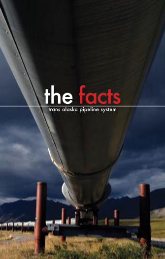
trans alaska pipeline systemthe facts

the facts.�
cover image courtesy of David Predeger

the facts.�
the facts.trans alaska pipeline system
�007
the facts.�
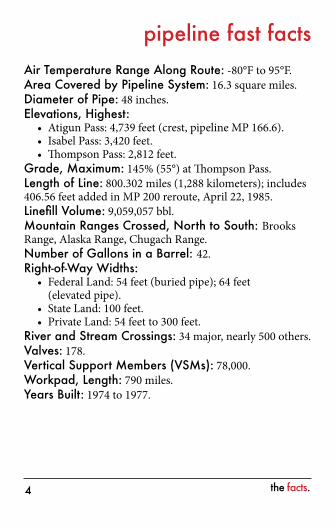
pipeline fast factsAir Temperature Range Along Route: -80°F to 95°F.Area Covered by Pipeline System: 16.3 square miles.Diameter of Pipe: 48 inches.Elevations, Highest:
Atigun Pass: 4,739 feet (crest, pipeline MP 166.6).Isabel Pass: 3,420 feet.Thompson Pass: 2,812 feet.
Grade, Maximum: 145% (55°) at Thompson Pass.Length of Line: 800.302 miles (1,288 kilometers); includes 406.56 feet added in MP 200 reroute, April 22, 1985.Linefill Volume: 9,059,057 bbl.Mountain Ranges Crossed, North to South: Brooks Range, Alaska Range, Chugach Range.Number of Gallons in a Barrel: 42.Right-of-Way Widths:
Federal Land: 54 feet (buried pipe); 64 feet (elevated pipe).State Land: 100 feet.Private Land: 54 feet to 300 feet.
River and Stream Crossings: 34 major, nearly 500 others.Valves: 178.Vertical Support Members (VSMs): 78,000.Workpad, Length: 790 miles.Years Built: 1974 to 1977.
•••
•
••
the facts.�
acronyms and abbreviations
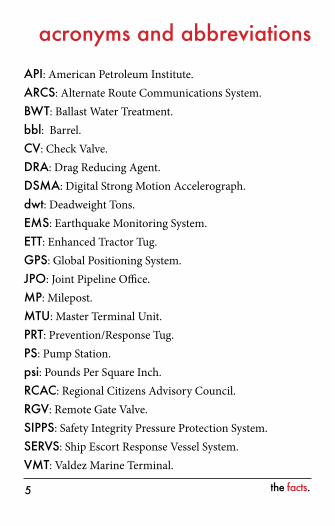
API: American Petroleum Institute.ARCS: Alternate Route Communications System.BWT: Ballast Water Treatment.bbl: Barrel.CV: Check Valve.DRA: Drag Reducing Agent.DSMA: Digital Strong Motion Accelerograph.dwt: Deadweight Tons.EMS: Earthquake Monitoring System.ETT: Enhanced Tractor Tug.GPS: Global Positioning System.JPO: Joint Pipeline Office.MP: Milepost.MTU: Master Terminal Unit.PRT: Prevention/Response Tug.PS: Pump Station.psi: Pounds Per Square Inch.RCAC: Regional Citizens Advisory Council. RGV: Remote Gate Valve.SIPPS: Safety Integrity Pressure Protection System. SERVS: Ship Escort Response Vessel System.VMT: Valdez Marine Terminal.
the facts.�
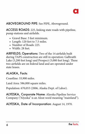
aABOVEGROUND PIPE: See PIPE, Aboveground.
ACCESS ROADS: 225, linking state roads with pipeline, pump stations and airfields.
Gravel Base: 3 feet minimum.Length: 120 feet to 7.5 miles.Number of Roads: 225.Width: 28 feet.
AIRFIELDS, Operations: Two of the 14 airfields built during TAPS construction are still in operation: Galbraith Lake (5,200 feet long) and Prospect (5,000 feet long). These two airfields are on federal land and are operated under state leases.
ALASKA, Facts:Coastline: 33,900 miles.Land Area: 586,000 square miles.Population: 670,053 (2006, Alaska Dept. of Labor).
ALYESKA, Corporate Name: Alyeska Pipeline Service Company (“Alyeska” is an Aleut word meaning “mainland”).
ALYESKA, Date of Incorporation: August 14, 1970.
••••
the facts.7
ALYESKA, Early History: Originally TAPS, for Trans Alaska Pipeline System (initially “Trans Alaska Pipeline Project”), a joint venture of Atlantic Pipe Line Company (now ConocoPhillips Transportation Alaska, Inc.), Humble Pipe Line Company (now ExxonMobil Pipeline Company) and BP Oil Corporation (now BP Pipelines (Alaska) Inc.) formed to develop a plan for construction of a pipeline for Prudhoe Bay oil.
ALYESKA, Internet Address: http://www.alyeska-pipe.com.
ALYESKA, Office Addresses:
Anchorage Office (Corporate Headquarters): Alyeska Pipeline Service Company 900 E. Benson Blvd. Anchorage, AK 99508 (907) 787-8700 Toll free: (877) 257-5778 Mailing Address: Alyeska Pipeline Service Company P.O. Box 196660 Anchorage, AK 99519-6660
Fairbanks Office: Alyeska Pipeline Service Company 701 Bidwell Ave. Fairbanks, AK 99701 Toll free: (877) 257-5778 Mailing Address: Alyeska Pipeline Service Company P.O. Box 60469 Fairbanks, AK 99706
the facts.�
SERVS Office: SERVS (Ship Escort Response Vessel System) P.O. Box 109 Valdez, AK 99686
Valdez Marine Terminal Office: Alyeska Pipeline Service Company P.O. Box 300 Valdez, AK 99686
Washington, D.C. Office: Alyeska Pipeline Service Company 1667 K St., NW, Suite 430 Washington, DC 20006 (202) 466-3866
ALYESKA, Owners: The consortium of companies that owns TAPS today includes: BP Pipelines (Alaska) Inc. 46.93%ConocoPhillips Transportation Alaska, Inc. 28.29%ExxonMobil Pipeline Company 20.34%Koch Alaska Pipeline Company, L.L.C. 3.08% Unocal Pipeline Company 1.36%
ALYESKA, Personnel: Approximately 2,000 people are employed to operate and maintain the Trans Alaska Pipeline System, including Alyeska and contractor employees. The Alyeska employees as of December 31, 2006 are:
Total Employees: Approximately 800 (The number of personnel working at pump stations varies throughout the year and is captured in the statistics for Anchorage, Fairbanks or Valdez).
•
the facts.�
Anchorage: 224.Fairbanks: 295.Valdez: 281.Alaska Residents: 97%, approximately.
ALYESKA, Responsibilities: Design, construct, operate and maintain the Trans Alaska Pipeline System.
ALYESKA TACTICAL OIL SPILL MODEL (ATOM): Software package specifically designed for oil spill trajectory modeling in Prince William Sound. ATOM is used to:
Forecast path of oil, based on real weather input.Show wildlife impact potential and other sensitivities such as recreational sites, commercial fishing areas and shoreline types.Show locations of Prince William Sound communities and hatcheries.
ANIMAL CROSSINGS, Mainline: The purpose is to allow for free movement of big game animals (caribou, moose, etc.) across the pipeline right-of-way. Approximately 579 animal crossings are incorporated into TAPS, including:
ANIMAL CROSSINGS, Elevated: 554 (minimum height 10 feet).
ANIMAL CROSSINGS, Buried: 23.
ANIMAL CROSSINGS, Buried, Refrigerated: Two (MP 645 and MP 649).
••••
••
•
the facts.�0
ARCHAEOLOGICAL SURVEY, Preconstruction: The entire TAPS route was surveyed by the University of Alaska and Alaska Methodist University under contract to Alyeska. The survey, which cost approximately $2.2 million, resulted in the excavation of approximately 330 sites.
ARCS (Alternate Route Communications System): A private radio network used by TAPS technicians for voice communications in remote locations.
ATOM (Alyeska Tactical Oil Spill Model): See ALYESKA TACTICAL OIL SPILL MODEL.
the facts.��
bBALLAST WATER TREATMENT (BWT): The Valdez Terminal treats tanker ballast water to remove oil.
Average Ballast Water Treated: 120,000 bbl/day.Capacity of System: 21,000 bbl/hour.Crude Oil Recovered from Ballast: 600 bbl/day average.Purity Standards: 1.0 parts per million aromatic hydrocarbons (daily maximum).
BALLAST WATER TREATMENT (BWT) FACILITY: Major Components:
Biological Treatment Tanks: Two aboveground concrete tanks with a capacity of 5.5 million gallons each.Diffuser Line at Discharge into Port Valdez: The line discharges at a maximum depth of 300 feet at a distance of 700 to 1,050 feet offshore.Dissolved Air Flotation (DAF) Units: Six cells, each 144 feet long, 24 feet wide and 12 feet deep.Piping from Berths to Tanks: 42-inch diameter.Time Required for Treatment: 24 hours average.Settling Tanks: Three tanks with capacity of 430,000 bbl each, 53 feet 6 inches high and 250 feet in diameter.
BARREL, Crude Oil: The normal unit of measurement for crude oil: 1 bbl = 42 gallons; 310.9 pounds per bbl.
BELOWGROUND PIPE: See PIPE, Belowground.
••••
•
•
•
•••
the facts.��
BIRD SPECIES: More than 170 identified along the TAPS route.
BRIDGE, Yukon River: Located at MP 353.3.Construction Dates: 1974-1975.Cost: $30 million (Owners’ share approximately $10 million).Dimensions: 2,295 feet long; road deck 30 feet wide; grade 5.99°.Name: Bridge officially named “E.L. Patton Yukon River Bridge” by Alaska Legislature in 1982, after E.L. Patton, President of Alyeska during pipeline construction. A monument to E.L. Patton was dedicated in October 1982.Opening Date: October 1979.River Width: 1,900 feet, typical.
BRIDGES, Pipeline: 13 total along TAPS.
BRIDGES, Road: 21 north of Yukon; 23 south of Yukon.
••
•
•
••
the facts.��
cCARIBOU: TAPS crosses the ranges of the Central Arctic Herd on the North Slope and the Nelchina Herd in the Copper River Basin.
CHRONOLOGY: See HISTORY, TAPS in appendix, page 73.
COLUMBIA GLACIER: Tidewater glacier in the northeast corner of Prince William Sound, at the head of Columbia Bay.
Calving Rate: 13 million tons/day, approximately.Distance from Tanker Lanes: 8 to 9 miles.Height: Approximately 0 to 150 feet above sea level, at terminus.Impact on Tankers: When the Captain of the Port determines hazardous ice conditions exist in Valdez Arm, the Valdez Narrows ice routing measures are placed into effect in accordance with the Prince William Sound Vessel Escort Response Plan.Largest Icebergs Produced: 30 feet high, 300 feet in diameter, approximately.Length: 35 miles, approximately.Water Depth at Face: 0 to 1,000 feet, approximately.Width: 3 miles, approximately, at terminus.
COMMUNICATIONS, (ARCS): See ARCS in acronyms and abbreviations.
•••
•
•
•••
the facts.��
COMMUNICATIONS SYSTEM: The primary communications system uses microwave, which is backed up by satellite.
COMMUNICATIONS SYSTEM, Central: Backbone communication system, remote gate valve, ARCS (Alternate Route Communication System). Control systems are provided for supervisory control and telemetering, seismic monitoring, and monitoring and control of remote gate valves.
COMMUNICATIONS SYSTEM, Enterprise Data Services: Voice, data, video, cable TV Enterprise data services are provided for business systems. The primary data system uses fiber optics, which is backed up by satellite.
CONCRETE WEIGHTS:Pipe Coating: Used at river crossings; weight 75,000 pounds per 40-foot section.Saddles: Used in floodplains; weight 18,500 pounds each.
CONSTRUCTION, Airfields: Seven, 2,500 to 3,000 feet long.Seven, 5,000 feet long (Galbraith Lake and Prospect continue to be used for TAPS purposes).
CONSTRUCTION, Camps:Largest Camp: Marine Terminal, 3,480 beds.Largest Pipeline Camp: Isabel Pass, 1,652 bedsNumber, 1974 to 1977: 29 total.Smallest Pipeline Camp: Sourdough, 112 beds.
•
•
••
••••
the facts.��
CONSTRUCTION, Contractors and Subcontractors: 2,000, approximately.
CONSTRUCTION, Cost: Approximately $8 billion for construction of entire system, including Valdez Terminal and pump stations, at conclusion of initial construction period in 1977. Does not include interest on capital investment or capital construction after 1977.
CONSTRUCTION, Ditch: See DITCH, Buried Pipeline.
CONSTRUCTION, Fatalities: See FATALITIES, Construction.
CONSTRUCTION, Hydrostatic Testing:Maximum, equivalent to 96% of specified minimum yield strength.Minimum, 125% of operating pressure or 750 psi, whichever was greater.
CONSTRUCTION, Materials:Gravel for Entire Project: 73 million cubic yards.Gravel for Workpad: 32 million cubic yards.Largest Piece Shipped: Floating tanker berth (3,250 tons).Shipped to Alaska: 3 million tons, approximately.
CONSTRUCTION, Notices to Proceed: See NOTICES TO PROCEED, Construction.
CONSTRUCTION, Permits: See PERMITS, Construction.
CONSTRUCTION, Time: 3 years, 2 months (April 29,
•
•
••••
the facts.��
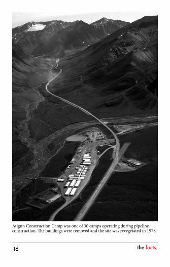
Atigun Construction Camp was one of 30 camps operating during pipeline construction. The buildings were removed and the site was revegetated in 1978.
the facts.�7
1974, to June 20, 1977) to complete pipeline, pump stations, roads and Terminal.
CONSTRUCTION, Time for Preconstruction Effort: 6 years, approximately.
CONSTRUCTION, Welding: See WELDS, Pipe.
CONSTRUCTION, Workforce: Minority Hire: Ranged from 14% to 19%.Peak, Contractors Only: 21,600.Peak, Total: 28,072 in October 1975 (Alyeska employees and contractors).Total for Project: 70,000 approximately (1969-1977).Women: Ranged from 5% to 10%.
CROSSINGS, Animal: See ANIMAL CROSSINGS.
CROSSINGS, Refrigerated, Road: The buried pipeline crossing of the Glenn Highway at Glennallen is refrigerated.
CRUDE OIL: A fluid made up of various hydrocarbon components, natural gas liquids and fixed gases.
CRUDE OIL, API Gravity: 29.9° API at 60°F for North Slope crude oil.
•••
••

the facts.��
CRUDE OIL, TAPS:Temperature in 2006: 111.7°F at injection into pipeline at PS 1. Approximately 57.6°F at Valdez Terminal.Throughput (2006 average): 759,081 bbl/day = 31,629 bbl/hour = 22,135 gallons/minute.Travel time in 2006: 11.9 days from PS 1 to Valdez Terminal. Velocity: 3.7 mph in pipeline.Weight: 310.9 pounds/bbl; 7.07 bbl/ton.
•
•
•
••
the facts.��
dDALTON HIGHWAY (Formerly North Slope Haul Road): James B. Dalton Highway is the name applied by the state in 1981 to 415 miles of roadway, including the North Slope Haul Road and the 57-mile road from the Yukon River to Livengood constructed by Alyeska in the winter of 1969-70 (this section of road was originally 56 miles, but one mile was added after realignment by the state at Livengood in 1981). James B. Dalton was a native-born Alaskan and graduate mining engineer who supervised construction of the Distant Early Warning (DEW) Line in Alaska. He was an expert in Arctic engineering and logistics and served as a consultant in early oil exploration in northern Alaska, pioneering winter trails for heavy equipment transport. The following information about the highway is current as of construction:
Bridges, Permanent: 20.Grade: 12% maximum.Gravel Used: 32 million cubic yards.
DALTON HIGHWAY, Haul Road Portion: See HAUL ROAD.
DALTON HIGHWAY, Ownership: Originally Alyeska; control transferred to the state in October 1978.
•••
the facts.�0
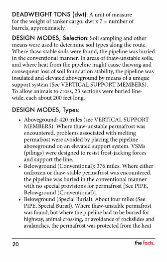
DEADWEIGHT TONS (dwt): A unit of measure for the weight of tanker cargo; dwt x 7 = number of barrels, approximately.
DESIGN MODES, Selection: Soil sampling and other means were used to determine soil types along the route. Where thaw-stable soils were found, the pipeline was buried in the conventional manner. In areas of thaw-unstable soils, and where heat from the pipeline might cause thawing and consequent loss of soil foundation stability, the pipeline was insulated and elevated aboveground by means of a unique support system (See VERTICAL SUPPORT MEMBERS). To allow animals to cross, 23 sections were buried line-wide, each about 200 feet long.
DESIGN MODES, Types:Aboveground: 420 miles (see VERTICAL SUPPORT MEMBERS). Where thaw-unstable permafrost was encountered, problems associated with melting permafrost were avoided by placing the pipeline aboveground on an elevated support system. VSMs (pilings) were designed to resist frost-jacking forces and support the line. Belowground (Conventional): 376 miles. Where either unfrozen or thaw-stable permafrost was encountered, the pipeline was buried in the conventional manner with no special provisions for permafrost [See PIPE, Belowground (Conventional)].Belowground (Special Burial): About four miles (See PIPE, Special Burial). Where thaw-unstable permafrost was found, but where the pipeline had to be buried for highway, animal crossing, or avoidance of rockslides and avalanches, the permafrost was protected from the heat
•
•
•
the facts.��
of the pipeline by insulation around the pipeline. Some special burials include ground refrigeration systems along with pipe insulations. Special burial locations:
– Atigun Pass: Two sections (about 1 mile) were buried in insulated boxes to provide protection from rockslides and avalanches.
– MP 645-649: Caribou crossing. – MP 653: Caribou crossing. – MP 681: Crossing of Glenn Highway. – 23 Animal crossings (All animal crossings are
special burial).
DISCHARGE PRESSURE: Pressure of the oil leaving a pump station.
DITCH, Buried Pipeline: 8 feet wide, 8 feet deep, approximately, but variable for overburden depth, which ranged from 3 to 35 feet.
DRAG REDUCING AGENT (DRA): A long-chain hydrocarbon polymer injected into the oil to reduce the friction due to turbulence in the oil.
DIGITAL STRONG MOTION ACCELEROGRAPH (DSMA): Field instrument to evaluate pipeline motion caused by earthquakes. See EARTHQUAKE, DSMAs. Pipe is wrapped before being placed in the trench during construction.
the facts.��
eEARTHQUAKE, Denali Fault, Nov. �, �00�: The pipeline withstood a magnitude 7.9 earthquake that was centered along the Denali Fault in Interior Alaska, approximately 50 miles west of the pipeline. The ground along the fault moved an estimated 18 feet horizontally and nearly 2.5 feet vertically. The quake was the largest on the Denali Fault since at least 1912 and among the strongest earthquakes recorded in North America in the last 100 years.
EARTHQUAKE, Design Magnitude: The pipeline is designed to withstand a maximum 8.5 Richter Scale earthquake at the Denali Fault. The range is 5.5 to 8.5, depending on area. The seismic design of TAPS includes two levels of earthquake hazards: the design contingency earthquakes (DCE) and the design operating earthquakes (DOE). The DCE corresponds to the design earthquake magnitude and may interrupt operations but not compromise the pipe. The DOE is a lower-intensity earthquake that has ground motion amplitudes one-half those of a DCE. Operations should be able to continue following a DCE.
EARTHQUAKE, Design Movement: Maximum movement of pipe at pipeline crossing of major faults:
Denali Fault: 20 feet lateral, 5 feet vertical.McGinnis Glacier Fault: 8 feet lateral, 6 feet vertical.Donnelly Dome Fault: 3 feet lateral, 10 feet vertical.Minor Potential Faults: 2 feet lateral, 2 feet vertical.
••••
the facts.��
EARTHQUAKE, DSMAs: The instrumentation at field locations consists of accelerometers mounted on concrete pads which measure strong ground motions in three directions (tri-axial) and are connected to a digital strong motion accelerograph (DSMA). The DSMA, generally located in the pump station control room, processes the signals from the accelerometers in real time and reports alarms and selected data to the central processor at the Operations Control Center (OCC).
EARTHQUAKE, Faults Crossed by Pipeline: Denali, McGinnis Glacier and Donnelly Dome.
EARTHQUAKE, Monitoring System (EMS): Alyeska’s EMS consists of sensing and processing instruments at Pump Station 1, at all pump stations south of Atigun Pass and at the Valdez Terminal. A central processing unit at the Operations Control Center is linked to the pipeline and terminal operator consoles. The EMS is specifically designed to process strong ground motions, to interpolate or extrapolate estimates of earthquake accelerations between the sensing instruments, and to prepare a mile-by-mile report comparing the estimated accelerations along the pipeline with the pipeline seismic design criteria. Field instrumentation consists of DSMAs (see EARTHQUAKE, DSMA).
EARTHQUAKE, Lateral Movement for Aboveground Pipeline: 2 feet maximum (predicted).
ENHANCED TRACTOR TUGS (ETT): Nanuq and Tan’erliq (Alaska Native words for “polar bear” and “black bear”). Designed for tethered tanker escort and oil spill response operations. The 153-foot vessels enhance SERVS’ ability to assist a disabled tanker. The state-of-the-art vessels have exceptional maneuverability and were deployed in 1999.

the facts.��
Crew: Seven trained response personnel.Firefighting: ABS Class 1 firefighting rating that includes pumps, monitors, foam and vessel spray system.Propulsion: Voith Schneider system; 10,192 hp.Spill Response Equipment:
– 2,000 feet of oil containment boom. – DESMI skimmers. – 70,000 gallons of recovered oil storage capacity. – Dispersant spray arm systems.
The Tan’erliq (far right), one of two enhanced tractor tugs at the Valdez Terminal.
••
••
the facts.��
fFATALITIES, Construction: 32 incidents directly related to construction (includes employees of Alyeska, contractors and subcontractors; excludes common carriers).
FATALITIES, Operations: Ten operations-related incidents (includes employees of Alyeska, contractors and subcontractors):
1977: PS 8 explosion. 1978: PS 8 snow-clearing accident.1984: Valdez Terminal heavy equipment accident. 1985: Charter aircraft accident (3), Glennallen. 1987: Security helicopter accident, Keystone Canyon. 1997: Vehicle accident, Haul Road. 2000: Vehicle accident, Valdez Terminal.2006: Tug operations accident, SERVS.
FAULT: See EARTHQUAKES, Faults.
FIRE SYSTEMS, Pump Stations: See PUMP STATIONS, Fire Systems.
FISH, Species: 34 identified in waters crossed by the pipeline.
FUEL GAS LINE: Carries natural gas from North Slope fields to fuel pump stations north of the Brooks Range. Generally parallels mainline crude oil pipeline, from Prudhoe Bay to PS 4. (Stations south of the Brooks Range are fueled by liquid turbine fuel.)
••••••••
the facts.��
Compressors: Two 1,200-hp gas turbine compressors at PS 1 boost gas pressure from approximately 600 psi to 1,100 psi.Diameter: 10 inches from PS 1 to MP 34 (34 miles); 8 inches from MP 34 to PS 4 (115 miles).Gas Temperature: 30°F, maximum (leaving PS 1).Length: 149 miles.Pig Launching/Receiving Facilities: PS 1, MP 34 and PS 4.Pressure: Design: 1,335 psi. Operating: 1,090 psi maximum currently.
FUEL, Required for All TAPS Operations (Fuel Oil Equivalent): 210,000 gallons/day.
•
•
•••
•
the facts.�7
gGABIONS AND CONCRETE MATS: Used in Atigun Floodplain Pipe Replacement Project as cover on pipe in shallow burial area for protection from natural erosion and scouring. A gabion is a metal cage filled with rock; gabions are used to stabilize banks.
Gabions: 31,750 feet.Concrete Mats: 9,525 feet.
GLENNALLEN: Town near south junction of Glenn and Richardson Highways.Population: 525 (2006, Alaska Dept. of Labor).Precipitation, Annual Average: 9 inches.Snowfall, Annual Average: 39 inches.Temperature Range, Average: -10°F to 56°F.
GRADE, Maximum on TAPS Route: 145% (55°) at Thompson Pass.
••
the facts.��
hHAUL ROAD: Portion of Dalton Highway from the Yukon River to Prudhoe Bay. Built by Alyeska.
Cost: $125 million, approximately.Dates: Started April 29, 1974; completed and dedicated September 29, 1974.Labor: 3 million hours.Time: 154 days.Length: 358 miles (Yukon River to Prudhoe Bay)
HEAT PIPES: These pipes contain anhydrous ammonia, which vaporizes at temperatures just below freezing, rises and condenses at radiators aboveground when the air temperature is well below freezing. This process transfers ground heat into the air during cold periods, thereby lowering the ground temperature. There are 124,300 individual heat pipes along the pipeline. See VERTICAL SUPPORT MEMBERS.
HISTORY, TAPS: See History in appendix, page 73.
••
•••
the facts.��
iINSULATION, Thickness:
Elevated pipeline: 3.75 inches thick.Refrigerated Belowground Pipeline: 3.2 inches thick.Under Gravel Workpad or Road: 2 to 4 inches.
INTERGRITY MANAGEMENT PLAN (IMP): Integrity management comprises of all activities to monitor and maintain the integrity of all hydrocarbon handling facilities on TAPS. The purpose of IMP is to protect the environment by preventing oil spills, comply with all laws and regulations, maintain facilities within industry standards, and monitor and mitigate integrity risks. Its mission is to move oil safely, reliably and efficiently.
•••
the facts.�0
JOINT PIPELINE OFFICE (JPO): Joint federal and state office set up with representatives of various agencies with responsibility for monitoring TAPS.
the facts.��
lLAND, Municipal Jurisdiction: Approximate pipeline length in each jurisdiction, north to south:
North Slope Borough: 179.2 miles.Fairbanks North Slope Borough: 89.1 miles.City of Delta Junction: 5.5 miles.City of Valdez: 20.8 miles.
LAND OWNERSHIP, Area: Approximate area for all of TAPS (18.4 square miles total):
State Government: 7.79 square miles. Federal Government: 6.27 square miles.Owner Companies: 2.9 square miles.Private: 1.41 square miles.
LAND OWNERSHIP, Owner: Approximate pipeline length for each ownership category (800 miles total):
Federal Government: 376 miles.State Government: 344 miles.Private: 80 miles (including 51 miles on Alaska Native Corporation land).
••••
••••
•••
the facts.��
LEAK DETECTION SYSTEM: Provides detection and location of oil spills. TAPS has three independent systems:
Line volume balance (LVB), which compares the volume of oil entering the line with the volume leaving it.Transient Volume Balance (TVB), which compares reported flow with calculated flow and can identify the probable location of a leak by pipeline section.Alarms which signal deviations in pressure, flow or flow rate balance.
LINEFILL: The oil necessary to fill the pipeline to start the pumps in a mechanically sound manner. At a throughput of 0.935 million bbl per day, the linefill volume is 9,059,622 bbl.
LIVING QUARTERS: See PUMP STATIONS, Living Quarters.
•
•
•
the facts.��
mMAXIMUM ALLOWABLE OPERATING PRESSURE: A rating indicating the maximum pressure at which a pipeline or segment of a pipeline may be operated under U.S. Department of Transportation regulations in normal conditions. Also called “pressure rating.”
MOUNTAIN RANGES, Crossed by Pipeline: Brooks Range, Alaska Range and Chugach Range.
MUTUAL AID AGREEMENTS: See OIL SPILL RESPONSE, Mutual Aid Agreements.

the facts.��
nNORTH SLOPE, Environment: A nearly flat, treeless plain, covering about 88,000 square miles extending from the foothills of the Brooks Mountain Range to the Arctic Ocean. For 56 days in winter the sun never rises. Winter twilight provides sufficient light for driving without headlights during the day. Winter temperatures drop to -60°F. Wind chill factor may fall as low as -135°F. From mid-April to mid-August, there is daylight 24 hours a day. Summer temperatures climb to 70°F and higher.
NORTH SLOPE, Oil Discovery: Exploratory drilling on the North Slope continued for more than 20 years; many unsuccessful exploratory wells were drilled and many companies gave up the search before the Prudhoe Bay discovery well was drilled by Atlantic Richfield Company and Humble Oil and Refining Company in 1967. A confirmation well the following year proved the discovery of the large oil and gas reservoir.
NORTH SLOPE, Oil Production Received at PS �:2006 Total: 277.06 million bbl.Cumulative Total, 1977 through 2006: 15.4 billion bbl.
NOTICES TO PROCEED, Construction: 465 federal and 403 state notices to proceed were required from the Federal Alaska Pipeline Office and the State Pipeline Coordinator’s Office.
••
the facts.��
oOIL SPILL CONTINGENCY PLAN, Pipeline: Trans Alaska Pipeline System Oil Discharge Prevention and Contingency Plan.
Containment Sites: 221 designated along drainages on TAPS. Criteria for selection: accessibility, river velocity, river channel configuration, environmental sensitivity. Equipment stored at containment sites varies per site; includes oil spill equipment, concrete anchors or underflow dam kits. Equipment: Varies by pump station. Total inventory available includes the following:
– Boats/Rafts: 35. – Boom, Containment: 46,700 feet. – Boom, Fire: 2,150 feet. – Storage Capacity: 22,630 bbl. – Vacuum Trucks: 12.
Leak Detection: Four systems. See LEAK DETECTION SYSTEMS.Personnel:
– Pipeline personnel trained in oil spill response. Each manned pump station has 24-hour oil spill response capabilities.
– Drills: Field drills are conducted to evaluate preparedness to react to an oil spill. The drills permit evaluation of the training
•
•
•
•
the facts.��
program, particularly oil spill skills such as reconnaissance, assessment and response.
– Training: Training for new employees and a two-day classroom refresher for existing employees with a minimum of two days field training.
OIL SPILL CONTINGENCY PLAN, Tankers: Tankers transiting Prince William Sound are required by the state to have oil spill contingency plans. The Prince William Sound Tanker Oil Discharge Prevention and Contingency Plan is a required part of each tanker’s individual contingency plan. Alyeska Pipeline/SERVS is the primary response action contractor responsible for the implementation aspects of the tanker plan. The prevention portion of this plan requires that each laden tanker transiting Prince William Sound must be escorted by two vessels, one of which must be a specially equipped prevention and response vessel or tug. Laden tankers are tethered to escort tugs from the Terminal through the Valdez Narrows and Valdez Arm. Also included in the plan are speed limits for tankers and weather restrictions. The response portion of the plan includes plans for open-water, nearshore shoreline responses and support operations.
OIL SPILL CONTINGENCY PLAN, Terminal: The Valdez Marine Terminal Oil Discharge Prevention and Contingency Plan includes a comprehensive prevention plan outlining spill prevention measures taken at the Terminal, as well as a response section describing land and water response for spills originating from Terminal facilities. A spill from a tanker at berth or transiting Port Valdez is covered under the Prince William Sound Tanker Oil Discharge Prevention and Response Plan. Although a spill from a tanker is the responsibility of the tanker owner, Alyeska provides initial spill response.
the facts.�7
Personnel: Oil spill response crews trained to conduct land and water response operations are available 24 hours/day. Equipment: The following equipment is stored in Valdez:
– Barges: Four tank barges (217,000 bbl, approximately, for recovered oil); one flat-deck barge with sensitive-area protection boom (serves as on-water staging location).
– Boom: For protection of sensitive areas. – Containment Boom: Over 21,000 feet. – Skimmers, Portable: Six barge-mounted; three
vacuum skimmers; 14 weir/disc skimmers. – Skimmers, Self-Propelled: Four total: JBF 6001
(Valdez Star) with recovery rate of 2,000 bbl/ hour and storage of 1,310 bbl; JBF 3003 (two units) with recovery rate of 571 bbl/hour; and MARCO Class VII with recovery rate of 1,281 bbl/hour.
– Tugs, Ship Assist: Four. – Vacuum Trucks: Three. – Work Boats: 10.
Prevention Programs: – Corrosion control programs. – Inspection and records. – Medical monitoring. – Preventive maintenance. – Security. – Substance abuse programs. – Tank leak protection. – Training programs. – Transfer procedures.
OIL SPILL RESPONSE, Mutual Aid Agreements: Provide additional equipment and resources for oil spill response.
•
•
•
the facts.��
OPERATIONAL INTEGRITY: An Alyeska program designed to assure the integrity of the pipeline system is maintained while attaining the highest standards of safety and environmental protection.
OPERATIONS CONTROL CENTER (OCC): The OCC continually monitors the status of all pump stations and valves using supervisory control and data acquisition (SCADA) systems with remote sensors. Data such as pressures, flow rates, temperatures, tank levels and valve positions are recorded and analyzed for abnormal operations or any indication of a pipeline leak. The pipeline controller at the OCC can rectify any abnormal operation by changing settings for pump speed or relief valves, or by issuing idle or stop commands to the mainline pumps. The OCC controller can also activate remote control valves. The monitoring and analysis systems include backup communications equipment and computers.
the facts.��
pPACKLINE: Oil flow that completely fills a pipeline.
PERMAFROST: Any rock or soil material that has remained below 32°F continuously for two or more years. The two-year minimum stipulation is meant to exclude from the definition the overlying ground surface layer which freezes every winter and thaws every summer (called the “active layer” or “seasonal frost”).
PERMAFROST, Affected Areas on TAPS: Approximately 75% of the line passes through permafrost terrain. The line traverses the continuous zone on the North Slope and through the Brooks Range; it then encounters the discontinuous and sporadic zones and passes through areas of no permafrost in the immediate vicinity of Valdez.
PERMAFROST, Depth Along Pipeline Route: A few inches to 2,230 feet, approximately.
PERMAFROST, Design Solutions: The pipeline design is based primarily on the soil conditions encountered along the right-of-way. There are three principal design modes: aboveground, conventional burial and special burial. See DESIGN MODES, Selection.
PERMAFROST, Problems:Frost-Heaving: When the active layer freezes, ice forms and pushes the ground surface upward.Frost-Jacking: When heaving occurs, if a structure embedded in the ground is not properly anchored
•
•
the facts.�0
to resist such movement, the structure will be forced upward along with the ground surface. In most cases, the structure does not return to its original position when the active layer thaws during the following summer. The net upward movement is called “jacking.” This phenomenon can occur whenever there is seasonal freezing and thawing of the active layer and is not limited to permafrost areas.Thaw Settlement: Structures founded on “thaw-unstable” permafrost may settle if large amounts of ice in the permafrost melt. Melting is typically caused by heat from the structure or changes to the natural thermal conditions.
PERMAFROST, Types:Cold Permafrost: Remains below 30°F (may be as low as 10°F as on the North Slope); tolerates introduction of considerable heat without thawing.Ice-Rich: 20% to 50% visible ice.Thaw-Stable: Permafrost in bedrock, in well-drained, coarse-grained sediments such as glacial outwash gravel and in many sand and gravel mixtures. Subsidence or settlement when thawed is minor, foundation remains essentially sound.Thaw-Unstable: Poorly drained, fine-grained soils, especially silts and clays. Such soils generally contain large amounts of ice. The result of thawing can be loss of strength, excessive settlement and so much moisture in the soil that it flows.Warm Permafrost: Remains just below 32°F. The addition of very little additional heat may induce thawing.
•
•
••
•
•

the facts.��
PERMAFROST, Zones:Continuous Zone: Permafrost is found almost everywhere in the zone, as the name implies. Includes all of the North Slope.Discontinuous Zone: Permafrost is found intermittently; includes much of the interior of the state.Sporadic Zone: Permafrost is found in isolated small masses of permanently frozen ground.
PERMANENT LIVING QUARTERS: See PUMP STATIONS, Living Quarters.
PERMITS, Construction: 515 federal and 832 state permits were required to build TAPS.
•
•
•
Permafrostmore than1,000' thickin many areas
Seasonallyfrozen active layer1' to 6'thick
Insulating tundra4" to 6" thick
Continuous
Permafrost in Alaska
Discontinuous No Permafrost
the facts.��
PIG: A mechanical device which is pushed through the pipeline by the oil. Consists of cone-shaped polyurethane cups on a central body which matches the shape of the interior pipe wall. Bumper nose, urethane construction and light weight prevent damage to check valve clappers. Several types of pigs are used to improve flow characteristics, inspect for dents and wrinkles, inspect for pipeline corrosion and measure pipeline curvature.
Batching: Used during initial linefill.Corrosion: A pig which detects corrosion or pitting in the pipe wall. These pigs may use different technologies to collect and record corrosion data. First run in 1978.
– Magnetic: Detects metal loss in pipe wall by measuring disturbances in a magnetic field. First run in 1978.
– Ultrasonic: Measures and records wall thickness of pipeline using ultrasonic transducers. First run in June 1989.
Curvature: A pig using an inertial navigation system to determine pipeline location, curvature and pipe wall deformation. First run in 1992.Deformation: A pig which measures the diameter of the pipe. Defines changes in pipe diameter caused by dents, ovalities, or pipe bending. Changes are recorded and analyzed by engineers. First run in 1979.Scraper: A pig used for cleaning and flow enhancement. First run in 1977.
••
•
•
•

the facts.��
TAPS employee cleans a scraper pig at the Valdez Marine Terminal. Scraper pigs, which clean the pipeline and enhance oil flow, are pushed by the oil.
PIG, Launching/Receiving Facilities: PS 1 (launch only), PS 4 (launch and receive) and Valdez Terminal (receive only).
PIG, Frequency: Smart pigs are run every three years. Scraper pigs are run every 7-14 days. Changes to this schedule are made based on operational needs. PIPE: The pipe for TAPS was manufactured in Japan (Italy for Atigun floodplain pipe replacement project).
Diameter, Outside: 48 inches (122 cm).Lengths, Standard: 40 feet and 60 feet.Pieces Required for Pipeline: Over 100,000.Tested to: Maximum axial force of 2.52 million pounds and lateral deflection force of 459,000 pounds before wrinkling (typical test sample: 31 feet 5 inches).Thickness, Wall: 0.462 inches (466 miles) and 0.562 inches (334 miles).
••••
•
image courtesy of David Predeger
the facts.��
Total Shipped: 550,000 tons, approximately. 120 shiploads for original construction; Six for Atigun Floodplain Pipe Replacement Project.Volumetric Displacement: 11,366 bbl/mile (0.462-inch thickness); 11,270 bbl/mile (0.562-inch thickness).Weight: 235 pounds/linear foot (0.462-inch thickness); 285 pounds/linear foot (0.562-inch thickness).
PIPE, Aboveground: Specially designed vertical supports were placed in drilled holes or driven into the ground. In warm permafrost (See PERMAFROST) and other areas where heat might cause undesirable thawing, the supports contain two, two-inch diameter pipes called “heat pipes,” containing anhydrous ammonia, which vaporizes belowground, and rises and condenses aboveground, removing ground heat whenever the air temperature is 5° to 10°F cooler than the ground temperature at the base of the heat pipe. Heat is transferred through the walls of the heat pipes to aluminum radiators atop the pipes. See VERTICAL SUPPORT MEMBERS.
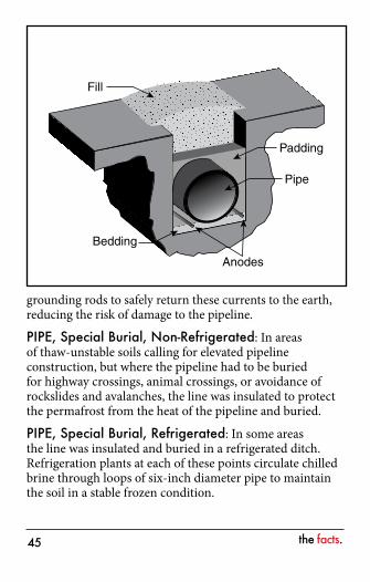
PIPE, Belowground (Conventional): The pipe is underlain with a layer of fine bedding material and covered with prepared gravel padding and soil fill material, in a ditch from 8 to 16 feet deep in most locations, but up to 49 feet deep at one location. Zinc ribbons, which serve as sacrificial anodes to inhibit corrosion of the pipe, are buried alongside the pipeline. (The Atigun pipe replacement section, 8.5 miles in length, has four magnesium ribbon sacrificial anodes installed.) Electrical currents in the earth’s surface, called “telluric currents” and caused by the same phenomenon that generates the Northern Lights, can be picked up by the pipeline and zinc/magnesium anodes. The anodes act like
•
•
•
the facts.��
grounding rods to safely return these currents to the earth, reducing the risk of damage to the pipeline.
PIPE, Special Burial, Non-Refrigerated: In areas of thaw-unstable soils calling for elevated pipeline construction, but where the pipeline had to be buried for highway crossings, animal crossings, or avoidance of rockslides and avalanches, the line was insulated to protect the permafrost from the heat of the pipeline and buried.
PIPE, Special Burial, Refrigerated: In some areas the line was insulated and buried in a refrigerated ditch. Refrigeration plants at each of these points circulate chilled brine through loops of six-inch diameter pipe to maintain the soil in a stable frozen condition.
Fill
Padding
Bedding
Anodes
Pipe
the facts.��
PIPE SHOES: 39,000, approximately.
PIPELINE SHUTDOWNS: See SHUTDOWNS, Pipeline in appendix, page 92.
PORT VALDEZ: A natural fjord 12 miles long, 2.5 miles wide and up to 800 feet deep, with a tidal range of 12 to 14 feet.
POWER PLANTS, Pump Station: See PUMP STATIONS, Power.
PRESSURE, Maximum Operating: 1,180 psi.
PRESSURE RELIEF STATION: PS 5 reinjects oil drained down for pressure relief but does not have mainline pumps and does not boost total stream.
PRESSURE RELIEF VALVE: A valve designed to open automatically to relieve pressure and keep it below a designated level.
PRESSURE SPIKE: A sudden, brief rise in pressure.
PRESSURE SURGE: A pressure spike/excursion moving through the pipeline at sonic velocity. Produced by a sudden change in velocity of the moving stream that results from shutting down a pump station or pumping unit, closure of a valve or any other blockage of the moving stream.
PREVENTION/RESPONSE TUGS (PRTs): Alert, Attentive and Aware. Specially designed for escorting and response service in Prince William Sound. Best technology for prevention and response missions by powerful ocean-class tugs. Deployed in 2000.

the facts.�7
Size: Approximately 140 feet long. Crew: Seven trained response personnel.Propulsion: Z drives; 10,200 horsepower. Fire Fighting: ABS Class 1 firefighting rating that includes pumps, monitors, foam and vessel spray systems.Spill Response Equipment:
– 2,000 feet Kepner Sea Curtain oil containment boom.
– Two DESMI skimmers. – Two 20-foot Kvichak workboats.
PRINCE WILLIAM SOUND REGIONAL CITIZENS ADVISORY COUNCIL (PWSRCAC OR RCAC): Independent citizen oversight of the Valdez Marine Terminal, an organization approved by the USCG as an alternative group under OPA 90. Group set up by the federal Oil Pollution Act of 1990. The PWSRCAC citizen oversight role is advisory.
Budget: 2.8 million per year (provided by Alyeska).Members:
– Alaska State Chamber of Commerce – Alaska Wilderness Recreation & Tourism
Association – Chugach Alaska Corporation – City of Cordova – City of Homer – City of Kodiak – City of Seldovia – City of Seward – City of Valdez (2) – City of Whittier – Community of Chenega Bay – Community of Tatitlek
••••
•
••
the facts.��
– Cordova District Fishermen United – Kenai Peninsula Borough – Kodiak Island Borough – Kodiak Village Mayors Association – Oil Spill Region Environmental Coalition – Prince William Sound Aquaculture Corporation
PRUDHOE BAY: A coastal feature of the Beaufort Sea, approximately 250 miles north of the Arctic Circle and 1,300 miles south of the North Pole. Also used generally to describe a land area of petroleum development of Alaska’s North Slope: 18th largest field in the world. Largest field in North America.
PUMPS, Booster: All pump stations have booster pumps to move oil from the storage tanks to the mainline. (PS 1 has three mainline booster pumps to boost oil pressure.) PS 5 also has injection pumps.
PUMPS, Definition:Full Head Pump: A two-stage pump with both impellers in series. It has one inlet and one outlet.Half Head Pump: A two-stage pump with both impellers in parallel. It has two inlets and two outlets. It can handle twice the flow of the full head but only produces half the (head) pressure rise.
PUMPS, Mainline Pumps:Half Head (60,000 gallons/minute each): PS 2 and 7.Full Head (20,000 gallons/minute each): All other pump stations.
PUMPS, Number Currently Operating: Two operating at PS 1, 3 and 9. One operating at PS 4 and 7. PS 5 is a relief station.
•
•
••
the facts.��
PUMP STATIONS: Original design called for 12 pump stations with 4 pumps each. PS 11 was never built. PS 5 was built as a relief station. Eight stations were operating at startup (PS 1, 3, 4, 6, 8, 9, 10 and 12). PS 8 pump building was destroyed by an explosion and fire on July 8, 1977, during startup; the station was recommissioned March 7, 1978. PS 2 was commissioned October 2, 1979; PS 7 was commissioned December 1, 1980. All 11 stations were operating at maximum throughput.
PUMP STATIONS, Crew: Varies per station; typically 10 to 25 employees. Shifts: one week on/one week off, or two weeks on/two weeks off, depending on station. Work days are 12 hours long.
PUMP STATIONS, Crude Oil Tank Capacity: PS 1: 420,000 bbl; PS 5: 150,000 bbl; all others: 55,000 bbl.
PUMP STATIONS, Electrical Power: All stations generate electrical power; PS 8, 9 and 12 also purchase commercially generated power.
PUMP STATIONS, Fire Systems:Fire Response Team: Pump station personnel.Fire Training: Annual live fire training and monthly fire response training; airfield rescue fire training provided at stations with airports. Each pump station has fire extinguisher training props.Fire Trucks: one per pump station. Pump stations with airports have designated fire-fighting trucks for the airfield.Types: Halon, water and foam, dry chemical, wet chemical and carbon dioxide.
••
•
•
the facts.�0
PUMP STATIONS, Fuel Requirements: 30,000 to 60,000 gallons per day average per station (fuel oil equivalent).
PUMP STATIONS, Living Quarters, Permanent: Permanent living quarters at PS 1, 2, 3, 4, 5, 6, 7, 10 and 12. PS 8 and 9 personnel live in nearby communities.
PUMP STATIONS, Power: All stations generate electrical power, with power plants ranging from 1.3 megawatts at PS 1 to 4.7 megawatts at PS 6, depending on availability of commercial power, presence of topping unit, and/or vapor recovery system. PS 8, 9 and 12 also purchase commercial power.
PUMP STATIONS, Refrigerated Foundations: PS 1, 2, 3, 5 and 6.
PUMP STATIONS, Status as of December �00�:PS 1, 3, 4, (5 relief station only), 7 and 9 operating.PS 2 ramped down July 1, 1997. PS 6 ramped down August 8, 1997.PS 8 ramped down June 30, 1996.PS 10 ramped down July 1, 1996.PS 11 was not built but has maintenance facilities. PS 12 placed in ramped down status April 1, 2005.
PUMP STATIONS, Topping Units: See TOPPING UNIT.
PUMP STATIONS, Turbines: Turbine engines drive the pumps. See TURBINES.
•••••••
the facts.��
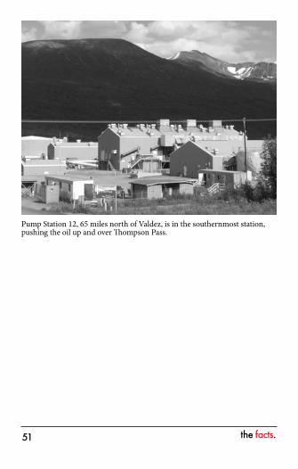
Pump Station 12, 65 miles north of Valdez, is in the southernmost station, pushing the oil up and over Thompson Pass.
the facts.��
rREGULATORY AGENCIES: The following agencies have jurisdiction over various aspects of TAPS. The asterisk denotes a member of the Joint Pipeline Office (JPO):
Alaska Department of Environmental Conservation*Alaska Department of Fish and Game*Alaska Department of Labor & Workforce Development*Alaska Department of Natural Resources*Alaska Department of Public SafetyAlaska Department of Transportation & Public FacilitiesAlaska State Fire Marshal*Regulatory Commission of AlaskaFederal Aviation AdministrationFederal Energy Regulatory CommissionFederal Maritime CommissionInterstate Commerce CommissionLocal Boroughs and Municipal GovernmentsU.S. Army Corps of EngineersU.S. Coast GuardU.S. Department of Commerce, National Oceanic and Atmospheric AdministrationU.S. Department of Interior, Bureau of Land Management*U.S. Department of Labor, Occupational Safety and Health AdministrationU.S. Department of Transportation, Office of Pipeline Safety*U.S. Environmental Protection Agency*U.S. Fish and Wildlife Service*U.S. National Transportation Safety Board
•••
•••••••••••••
••
•
•••
the facts.��
REPAIRS, Major: See REPAIRS, Major in appendix, page 86.
RESTORATION, Area Revegetated: Nearly 7,750 acres (through 1997).
RESTORATION, Basic Data:Area: Approximately 550 acres. Camps, Pad Restoration: 14.Fertilizer Used: 5,500 tons.Grass Seed Used: More than 450 tons.Seedlings Planted: 83,500.Soil Samples, Random: 15,000 to test for regeneration.Trees Transplanted: 24,000.
RESTORATION, Visual Impact Stipulations: See VISUAL IMPACT STIPULATIONS.
RIGHT-OF-WAY WIDTH:Federal Lands: 54 feet (buried pipe); 64 feet (elevated pipe).State Lands: 100 feet.Private Lands: 54 feet to 300 feet.
ROAD CROSSINGS, Pipeline: 21 north of Yukon; 23 south. The crossing at the Glenn Highway in Glennallen is refrigerated.
•••••••
•
••
the facts.��
sSAFETY, Philosophy: Alyeska’s safety philosophy is to strive for zero accidents and injuries.
SAFETY, Statistics: See FATALITIES.
SERVS (Ship Escort Response Vessel System): The mission of SERVS, which was established July 10, 1989, is to prevent oil spills by assisting tankers in safe navigation through Prince William Sound and to protect the environment by providing effective response services to the Valdez Marine Terminal and Alaska crude oil shippers in accordance with oil spill response agreements and plans.
SERVS, Boom: Over 42 miles of various types of oil containment boom are available at SERVS.
SERVS, Enhanced Tractor Tugs: See ENHANCED TRACTOR TUGS (ETTs).
SERVS, Fishing Vessels: 350 contracted vessels.
SERVS, Non-Mechanical Response Equipment:ADDS Pack: Two Airborne Dispersant Delivery Systems; treatment potential: 2,600 bbl/payload.Helitask Airborne Dispersant Systems(2): Treatment potential 4,200 gallons/payload.Heli-torch: Two airborne ignition systems.Spill Spray: Three meter-controlled dispersant spray units; onboard tankage 3,000 gallons concentrate liquid.SERVS, Pre-staged Equipment: Hatcheries and Sensitive Areas: Lake Bay, Cannery Creek, Solomon
•
•
••
•
the facts.��
Gulch, Main Bay, Sawmill Bay, Valdez Duck Flats and 10 Port Valdez sensitive areas.Others: Naked Island, Port Etches, Whittier, Cordova, Chenega Bay and Tatitlek.
SERVS, Prevention/Response Tugs: See PREVENTION/RESPONSE TUGS (PRT).
SERVS, Response Barges: Six.Barges with Skimmers: Four barges each have three open-class major skimming systems mounted aboard (three TransRec 350 skimmers and one GrahamRec skimmer).Dedicated Nearshore Barge: Responder 500-2.Lightering Barge: one.Total Storage Capacity: More than 780,000 bbl.
SERVS, Response Centers: Chenega Bay, Cordova, Tatitlek, Valdez and Whittier.
SERVS, Skimmers: More than 100.Skimming Capacity: Ranges from greater than 3,000 bbl/hour to small systems for operating in shallow water.Total Recovery Capacity: More than 75,000 bbl/hour.Valdez Star Oil Spill Recovery Vessel: 123-foot vessel with dynamic-inclined-plane skimming system with a design skimming capacity of 2,000 bbl/hour.
SERVS, Vessels (Other): SERVS has five vessels besides the PRTs and ETTs. These five include docking tugs and the Endurance, an emergency response vessel.
SERVS, Wildlife Hazing: Capture and rehabilitation plans are in place for spill response support.
SHIP ESCORT RESPONSE VESSEL SYSTEM: See SERVS.
•
•
•••
•
••
the facts.��
SHUTDOWNS, Pipeline: See SHUTDOWNS, Pipeline in appendix, page 92.
SLACKLINE: Oil flow that does not completely fill a pipeline. SOIL SURVEYS, Pre-construction:
Bore holes: 3,500, approximately.Soil samples: 15,000, approximately.
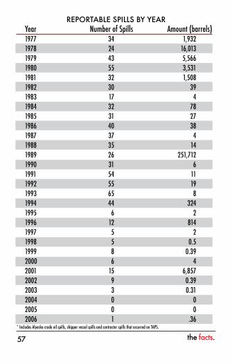
SPILLS, Reported: The table on the next page lists the yearly totals for spills that are reported by regulation to agencies. These spills include Alyeska spills, shipper vessel spills and contractor spills that occurred on TAPS.
STRATEGIC RECONFIGURATION: Strategic Reconfiguration is part of Alyeska’s overall vision to renew assets and its organization. Strategic Reconfiguration began in 2001 and concentrates on reducing physical infrastructure and simplifying operations and maintenance. The program goal is to position TAPS for more efficient operation while maintaining or enhancing safety, operational integrity and environmental performance. The new system is modular and scalable and will provide more flexibility for future increases or decreases in throughput. A more cost effective transportation system will better position the North Slope for future exploration, development and production. In 2006, a decision was made to focus on converting one station at a time. PS 9 near Delta Junction was selected as the first station to upgrade. It will be followed by PS 3, PS 4 and PS 1.
SUCTION PRESSURE: Pressure of the oil as it enters a pump station.
••
the facts.�7
REPORTABLE SPILLS BY YEARYear NumberofSpills Amount(barrels)1977 34 1,9321978 24 16,0131979 43 5,5661980 55 3,5311981 32 1,5081982 30 391983 17 41984 32 781985 31 271986 40 381987 37 41988 35 141989 26 251,7121990 31 61991 54 111992 55 191993 65 81994 44 3241995 6 21996 12 8141997 5 21998 5 0.51999 8 0.392000 6 42001 15 6,8572002 9 0.392003 3 0.312004 0 02005 0 02006 1 .36
*IncludesAlyeskacrudeoilspills,shippervesselspillsandcontractorspillsthatoccurredonTAPS.
the facts.��
tTANKER VAPOR CONTROL SYSTEM, VMT: Berths 4 and 5 are fitted with vapor recovery arms to collect vapors released during tanker loading. Operation of the system began on March 19, 1998.
TANKERS, Aids to Navigation and Safety:Major light house, light towers, differential GPS coverage, radar reflectors, racons, fog signals, buoys, day markers and strobe beacons.The U.S. Coast Guard maintains a vessel traffic service which includes radio/telephone communications with vessels, GPS-based transponder surveillance system in the Gulf of Alaska approaches and Prince William Sound, and two radar sites providing coverage in Port Valdez, the Valdez Narrows and Valdez Arm.Vessels are escorted through Prince William Sound.Ice navigation rules/restrictions and wind restrictions apply to tanker operations in the Sound.
TANKERS, Alyeska Role: The tankers that carry oil from the Valdez Marine Terminal are not owned by Alyeska. The role of Alyeska is to operate the Terminal and SERVS on behalf of the tanker owners. Alyeska, through SERVS, is contracted as a primary response action contractor to provide services in the event or threat of an oil spill from a tank vessel carrying crude oil that has been transported by TAPS.
•
•
••
the facts.��
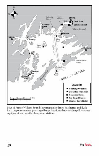
Map of Prince William Sound showing tanker lanes, hatcheries and duck flats, response centers, pre-staged barge locations that contain spill response equipment, and weather buoys and stations.
the facts.�0
TANKERS, Approach Routes:Gulf of Alaska to Prince William Sound to Port Valdez, via Hinchinbrook Entrance following dedicated traffic lanes to Valdez Arm and Valdez Narrows.Hinchinbrook Entrance: 6.4 to 6.8 miles clearance.
TANKERS, Classification:General Purpose: Up to 25,000 dwt.Super Tanker: 25,000 to 150,000 dwt.Very Large Crude Carrier (VLCC): 150,000 to 300,00 dwt.Ultra Large Crude Carrier (ULCC): More than 300,000 dwt.
TANKERS, Draft of Largest Tankers: 85 feet.
TANKERS, Escorts: Outbound laden tankers are escorted by two tugs from the marine terminal to Cape Hinchinbrook, a distance of approximately 70 miles with a standby while the tanker moves 17 miles seaward. One of the tugs is attached to the tanker (tethered) for the first 20 miles to provide immediate assistance if required. Inbound tankers (in ballast) are provided a standby sentinel escort from the Gulf of Alaska to the marine Terminal. Several years ago, Alyeska invested more than $75 million in new escort tug technology and tug construction. The cornerstone of the 10-tug escort fleet includes two 10,000-hp Voith Schneider tractor tugs and three 10,000-hp Z-drive tugs. The tanker escort system in Prince William Sound uses complementary best available technology and is unsurpassed anywhere in the world.
•
•
•••
•
the facts.��
TANKERS, Largest Berthed and Loaded to Date: 270,000 dwt.
TANKERS, Natural Phenomena Affecting Movements:
High Winds: The Valdez Narrows is closed to all tanker traffic if the winds exceed 40 knots.Cape Hinchinbrook: When the winds exceed 45 knots or the seas exceed 15 feet, Hinchinbrook Entrance is closed to laden tankers.Glacier Ice: The U.S. Coast Guard Prince William Sound Vessel Traffic Center may impose ice routing measures as appropriate. These may include moveable one-way zones, daylight-only restrictions or closure to tankers. (See also COLUMBIA GLACIER.)
TANKERS, Number Loaded per Month: 26 average (2006).
TANKERS, Size that can be Berthed and Loaded:Berth 1: 120,000 dwt (out of service).Berth 3: 250,000 dwt (not in use).Berths 4 and 5: 270,000 dwt.
TANKERS, Traffic Lanes:Depths Along: 600 to 1,000 feet average; 350 feet minimum (in Valdez Narrows).Distance Separating: 1 mile.Width: 3/4 mile.Valdez Narrows: One-way traffic; clearance 1,000 yards from Middle Rock to southeast shore.
TANKERS, Turnaround Time at Terminal: 22 hours, 20 minutes, average, for berthing, offloading ballast, loading crude and deberthing.
•
•
•
•••
•
•••
the facts.��
TELLURIC CURRENTS: Electrical currents in the earth’s surface, caused by the same phenomenon that generates the Northern Lights.
THERMAL EXPANSION: Change in pipe length due to change in crude oil temperature.
Tie-in Temperature: Actual pipe temperatures at the time when final welds were made which joined strings of pipe into a continuous line.Hot Position: Pipe at maximum oil temperature (145°F).Cold Position: Pipe at minimum steel temperature (-60°F, pre-startup).Each 40-foot length of pipe expands 0.031 inches with each 10°F rise in temperature and contracts the same distance with each 10°F drop in temperature.Longitudinal expansion of typical 720-foot straight aboveground segment from minimum tie-in temperature to maximum operating temperature: 9 inches. (Note: Due to anchoring, the pipeline does not expand lengthwise but shifts laterally on the aboveground supports.) See ZIGZAG CONFIGURATION. Maximum Aboveground Lateral Movement:
– Tie-in to hot position: 8 feet. – Tie-in to cold position: 4 feet.
Thermal Stress: Maximum 25,000 psi where belowground pipeline is fully restrained by the soil (the maximum longitudinal stress due to change in temperature from pipe temperature at tie-in to maximum oil temperature).
THROUGHPUT: The amount of North Slope crude oil transported from Pump Station 1 to the Valdez Marine Terminal.
•
•
•
•
•
•
•
the facts.��
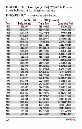
THROUGHPUT, Average (2006): 759,081 bbl/day, or 31,629 bbl/hour, or 22,135 gallons/minute.
THROUGHPUT, History: See table below.TAPS THROUGHPUT (barrels)
Year DailyAverage YearlyTotal CumulativeTotal1977 575,897 112,300,000 112,300,0001978 1,087,695 397,008,750 509,308,7501979 1,281,580 467,777,848 977,086,5981980 1,516,213 554,934,043 1,532,020,6411981 1,523,472 556,067,441 2,088,088,0821982 1,619,566 591,141,545 2,679,229,2671983 1,646,188 600,858,560 3,280,088,1871984 1,663,487 608,836,116 3,888,924,3031985 1,780,512 649,886,953 4,538,811,2561986 1,823,110 665,434,992 5,204,246,2481987 1,963,458 716,662,005 5,920,908,2531988 2,033,082 744,107,885 6,665,016,1081989 1,885,102 688,062,255 7,353,078,3631990 1,793,292 654,551,673 8,007,630,0361991 1,822,396 665,174,678 8,672,804,7141992 1,746,893 639,363,127 9,312,167,8411993 1,619,787 591,222,326 9,903,390,1671994 1,587,177 579,319,503 10,482,709,6701995 1,523,120 555,938,859 11,038,648,5291996 1,435,810 525,506,504 11,564,155,0331997 1,334,507 487,094,963 12,051,249,9961998 1,206,839 440,496,271 12,491,746,2671999 1,078,146 393,523,457 12,885,269,7242000 999,202 365,707,875 13,250,977,5992001 992,000 362,131,000 13,613,108,3622002 1,000,916 365,334,233 13,980,609,4562003 993,000 362,554,000 14,323,163,1562004 935,134 342,249,701 14,685,413,1572005 891,104 325,252,788 15,008,657,8312006 759,081 277,064,405 15,377,064,405
the facts.��
THROUGHPUT, Maximum Daily: 2.136 million bbl average (with 11 pump stations operating). Rates exceeding 1,440,000 bbl/day assume injection of drag reducing agent (DRA).
THROUGHPUT, Maximum Daily (2006): 1 million bbl average (with 7 pump stations operating). Rates exceeding 1,000,000 bbl/day assume DRA injection.
TOPPING UNIT: Mini-refinery that produces turbine fuel. Topping units are located at PS 6, 8 and 10, and all are ramped down. The unit at PS 10 was ramped down in 1995, the unit at PS 8 in 1996 and the PS 6 unit in 1997.
TURBINES, Fuel Requirements: Gas-Fired Units: 4.3 million cubic feet/unit/day average.Liquid-Fired Units: 30,000 gal/unit/day average (half head configuration); 24,000 gal/unit/day average (full head configuration).
TURBINES, Power Ratings: (Sea Level, 59°F):Avon Gas Generator: 24,600 exhaust gas horsepower.Reaction Turbine: 18,700 brake horsepower (half head configuration); 15,300 brake horsepower (full head configuration).
••
••

the facts.��
uULTRA LARGE CRUDE CARRIER (ULCC): tanker more than 300,000 dwt.
ULTIMATE STRENGTH: The stress level at which the pipe will fail/rupture or “break”. The ultimate strength of the steel is determined by testing during manufacture of the pipe.

the facts.��
vVALDEZ MARINE TERMINAL (VMT): The VMT, the southern terminus of the trans-Alaska pipeline, is located on ice-free Port Valdez at the northeastern end of Prince William Sound. The VMT site occupies approximately 1,000 acres on the southern shore of Port Valdez. The Terminal was designed to load tankers and to provide the storage capacity in TAPS to allow production on the North Slope to operate without impact-related delays from the marine transportation system. The Terminal, which has four tanker loading berths, has storage facilities with a working inventory capacity of 8.78 million barrels (bbl) of crude oil and a total volume of 9.18 million bbl.
VALDEZ MARINE TERMINAL, Berths: Four berths were built at the terminal: Berths 3, 4 and 5 (fixed platform) and Berth 1 (floating platform with 13 buoyancy chambers and weighing 6.5 million pounds.) Berth 1 is out of service and Berth 3 is used as a lay berth for tankers.
VALDEZ MARINE TERMINAL, Cost to Build: $1.4 billion.
VALDEZ MARINE TERMINAL, Elevation: Sea level to 660 feet. All facilities except berths are 15 feet or higher.
VALDEZ MARINE TERMINAL, Emergency Shutoff Valves: Crude oil loading onto a tanker can be shut down in less than 10 seconds at loading rates up to 100,000 bbl/hour.
the facts.�7
VALDEZ MARINE TERMINAL, Fire Fighting:Fire Boats: Six (tugs equipped with fire fighting equipment).Fire Trucks: Four.Personnel Training: All Terminal technicians trained to incipient level; advanced training for exterior and interior level fire brigade members; annual refresher for all three levels.Systems: Portable extinguishers, water and foam systems, Halon, carbon dioxide.
VALDEZ MARINE TERMINAL, Fuel Requirements: All Terminal and SERVS operations (fuel oil equivalent) 500 bbl/day average.
VALDEZ MARINE TERMINAL, Power Generation:Primary Plant Facilities:
– Three steam boilers each with an output of 175,000 pounds/hour at 600 psi at 750°F, steam, each.
– Three condensing steam turbine generators each with a capacity of 12.5 megawatts at 13.8 kilovolts.
Standby Systems: – Two 12-cylinder diesel generators: capacity 2.8
megawatts total. – Four uninterruptable power supply systems
supplied by 125-volt battery bank for essential control equipment.
VALDEZ MARINE TERMINAL, Stack Heights: Boiler, 300 feet; incinerators (four) 108 feet.
•
••
•
•
•
the facts.��
VALDEZ MARINE TERMINAL, Storage Tanks (Crude):
• Capacity: 510,000 bbl each; 9.18 million bbl total volume.• Dimensions: Height 63.3 feet, diameter 250 feet.• Floor Thickness: 1/4-inch steel plate (on concrete
ring wall).• Number: 18.• Roof: Fixed, conical.• Roof Supports: 61 columns, diameter 24 inches.• Slosh Zone: 3 feet, 9 inches.• Space Enclosed: 1.2 acres each, approximately.• Wall Thickness: Graduated from 1-1/8 inch steel
bottom ring, to 1/2 inch top ring.• Working Inventory: Average 85% of maximum or 7.8
million bbl (approximately 7.8 days of inventory at 0.999 million bbl/day).
VALDEZ MARINE TERMINAL, Storage Tanks (Crude) Containment Dikes:
Capacity: 110% capacity of both tanks, which accounts for water and snow accumulation.Number of Tanks in Each: Two.Reinforcing Steel: 52 miles in each, diameter 1/2 to 3/8 inch.
VALDEZ MARINE TERMINAL, Tanker Vapor Control System: See TANKER VAPOR CONTROL SYSTEM, VMT.
VALDEZ MARINE TERMINAL, Vapor Recovery: Five rotary compressors each rate at 13,500 standard cubic feet/minute. Two compressors are dedicated to recovering vapors from storage tanks, two compressors dedicated to recovering vapors from tanker berths and one swing compressor that can provide either function.
•
••
the facts.��
VALDEZ MARINE TERMINAL (VMT), Workforce: At peak of construction: 4,300.
VALDEZ NARROWS, Clearance: 1,000 yards: Middle Rock to southeast shore.
VALDEZ, Port: See PORT VALDEZ.
VALVE, Block: When closed, the valve can block oil flow in either direction. Block valves include manual gate valves, remote gate valves, and station block valves (suction valves and discharge valves).
Manual Gate Valve: Block valve that is operated manually; placed in check valve segments periodically to provide more positive isolation than can be provided by check valves during pipeline maintenance.Remote Gate Valve (RGV): A remotely controlled block valve for the primary purpose of isolating segments of the line in the event of a catastrophic pipeline break. Valve operating times are either four or eight minutes to fully open or fully close.Station Block Valve: A gate valve installed at the inlet (suction) side and the outlet (discharge) side of the pump station or Terminal to isolate the facility from the pipeline in the event of an emergency.
VALVE, Check: A valve that operates one-way and prevents the reverse flow of oil. Check valves are designed to be held open by flowing oil and to drop closed automatically when oil flow stops or is reversed. To increase operating efficiency, some check valves are held fully open mechanically, thus lifting valve clappers entirely free of the oil stream, reducing turbulence. Actuators fitted to these
•
•
•
the facts.70
valves receive signals from flow or pressure sensors to drop the valve clappers free. Once the clappers have been released, the actuated check valve functions as a normal check valve to stop flow reversal. Approximately one-half of the mainline check valves are fitted with hydraulic actuators; the remainder have manual actuators only.
VALVE, Pipeline:Check: 83.Gate: 71 (62 remotely operated, 9 manually operated).Block: 24.Total: 178.
VALVE, Pressure Relief: A valve designed to open automatically to relieve pressure and keep it below a designated level.
VALVES, Pump Stations and Terminal:Size: 2 to 48 inches.Design Pressure: Varies to meet process conditions. (Class 150# through Class 2500#).Type: Gate, ball, check, plug, etc.Number of Motor-Operated Valves: Approximately 1,000.
VALVE REPAIR PROGRAM: The program’s goal is to evaluate the conditions of TAPS valves, actuators, and operators as appropriate and to implement a comprehensive maintenance program to ensure long-term system integrity.
VAPOR RECOVERY: See VALDEZ MARINE TERMINAL, Vapor Recovery.
••••
••
••
the facts.7�
VERTICAL SUPPORT MEMBERS (VSM): Pipe embedded in the ground to support the aboveground pipe in areas of thaw-unstable permafrost. Some VSMs contain heat pipes to remove heat and keep the ground frozen.
Number: 78,000.Depth Embedded: 15 to 70 feet.Distance Between: Anchor supports, 800 to 1,800 feet; standard supports, 60 feet, approximately.Number Fitted with Heat Pipes: 61,000 (122,000 individual heat pipes, 2 per VSM where fitted).
VISUAL IMPACT STIPULATIONS:Access Roads: 12° maximum allowable grade. Buffer Strips (Undisturbed Land):
– 300-foot width of undisturbed land along streams.
– 500-foot width required between state highways and material sites.
– 1/2 mile required between workpads and parks, refuges, etc.
Right-of-Way Visibility: Maximum straight length permitted visible from highway: 600 feet.
VERY LARGE CRUDE CARRIER (VLCC): Tanker 150,000 to 300,000 dwt.
•••
•
••
•
the facts.7�
wWATERFLOOD: An oil field term referring to a system of pumping water into the oil reservoir behind the produced oil to maintain reservoir pressure and ultimately recover more oil.
WELDS, Pipe:Double Joints: 42,000 (a “double joint” is two pipe sections welded into a single length before transport to the field for placement in the line).Field Girth Welds: 66,000. Passes for Field Girth Welds: Seven for 0.562-inch pipe; six for 0.462-inch pipe.
WORKFORCE, Construction: See CONSTRUCTION, Workforce.
•
••

the facts.7�
yYIELD STRENGTH: The stress level above which the pipe will yield, bend and/or stretch.
the facts.7�
zZIGZAG CONFIGURATION: Aboveground sections of the pipeline are built in a zigzag configuration to allow for expansion or contraction of the pipe because of temperature changes. The design also allows for pipeline movement caused by an earthquake.
the facts.7�
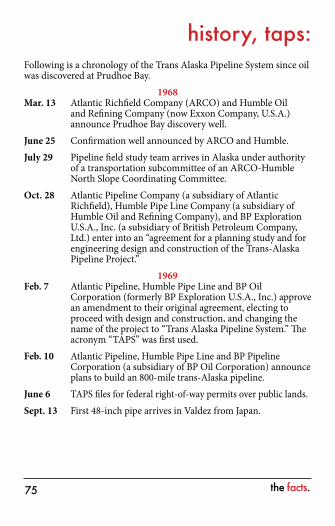
history, taps:Following is a chronology of the Trans Alaska Pipeline System since oil was discovered at Prudhoe Bay.
1968Mar. 13 Atlantic Richfield Company (ARCO) and Humble Oil
and Refining Company (now Exxon Company, U.S.A.) announce Prudhoe Bay discovery well.
June 25 Confirmation well announced by ARCO and Humble.July 29 Pipeline field study team arrives in Alaska under authority
of a transportation subcommittee of an ARCO-Humble North Slope Coordinating Committee.
Oct. 28 Atlantic Pipeline Company (a subsidiary of Atlantic Richfield), Humble Pipe Line Company (a subsidiary of Humble Oil and Refining Company), and BP Exploration U.S.A., Inc. (a subsidiary of British Petroleum Company, Ltd.) enter into an “agreement for a planning study and for engineering design and construction of the Trans-Alaska Pipeline Project.”
1969Feb. 7 Atlantic Pipeline, Humble Pipe Line and BP Oil
Corporation (formerly BP Exploration U.S.A., Inc.) approve an amendment to their original agreement, electing to proceed with design and construction, and changing the name of the project to “Trans Alaska Pipeline System.” The acronym “TAPS” was first used.
Feb. 10 Atlantic Pipeline, Humble Pipe Line and BP Pipeline Corporation (a subsidiary of BP Oil Corporation) announce plans to build an 800-mile trans-Alaska pipeline.
June 6 TAPS files for federal right-of-way permits over public lands.Sept. 13 First 48-inch pipe arrives in Valdez from Japan.
the facts.7�
Oct. 22 Humble Pipe Line, Atlantic Pipeline, and BP Pipeline are joined by Amerada Hess Corporation, Home Pipeline Company, Mobil Pipeline Company, Phillips Petroleum Company and Union Oil Company of California in joint venture.
December Alyeska builds road from Livengood to the Yukon River (winter of 1969-1970).
1970April Suits are filed by environmental groups and others to block
pipeline construction.Aug. 27 Trans Alaska Pipeline System Agreement made and signed
by Atlantic Pipeline Company, BP Pipeline Corporation, Humble Pipe Line Company, Amerada Hess Corporation, Home Pipeline Company, Mobil Pipeline Company, Phillips Petroleum Company and Union Oil Company of California all referred to as “TAPS Owners.”
Aug. 27 TAPS Owners formed Alyeska Pipeline Service Company, a separate corporation.
Aug. 27 Agreement made to design and construct the trans-Alaska pipeline. Alyeska Pipeline Service Company appointed as contractor and agent for the construction project.
1971Jan. 1 Atlantic Pipeline Company (TAPS Owner) stock reissued
to ARCO Pipeline Company.1973
Nov. 16 Trans Alaska Pipeline Authorization Act (TAPAA) becomes law.
1974January Home Pipeline Company (TAPS Owner) stock reissued to
six other oil pipeline companies.Jan. 3 Federal right-of-way grant issued.Apr. 29 Construction of road from Prudhoe Bay to Yukon River begins.May 3 State right-of-way lease issued.Sept. 29 Road from Prudhoe Bay to Yukon River completed.
the facts.77
Dec. 19 Humble Pipe Line Company (TAPS Owner) stock reissued to Exxon Pipeline Company.
1975Mar. 27 First pipe laid at Tonsina River.Oct. 11 Yukon River Bridge completed.Oct. 26 Pipeline project 50% complete.
1977May 20 Operating agreement established between Alyeska Pipeline
Service Company (as agent) to operate and maintain TAPS on behalf of TAPS Owners.
May 31 Final pipeline weld near PS 3.June 20 First oil flows from PS 1 (10:06 a.m. AST, pig in trap; 10:27
a.m. AST, pig depart signal).June 24 Oil front at PS 3 (12:56 p.m.).June 25 Oil front at PS 4 (7:50 a.m.).June 28 Oil front at PS 5 (6:23 a.m.).July 1 Oil front at PS 6 (6:30 p.m.).July 4 Nitrogen leak detected ahead of oil front, MP 489.12 (near
PS 8 north block valve). Oil flow stopped.July 7 Pipe repair, MP 489.12. Pipe and elbow cracked from
injection of supercooled nitrogen. Pipe replaced.July 7 Oil front at PS 8 (9:24 p.m.).July 8 PS 8 pump building destroyed by explosion and fire; 1
fatality; oil loss, 300 bbl.July 19 Oil leak (heavy equipment accident) at CV 7, 1,800 bbl.July 20 Oil front at PS 9 (10:37 a.m.).July 22 Oil front at PS 10 (4:46 a.m.).July 26 Oil front at PS 12 (3:48 a.m.).July 28 Oil reaches VMT (11:02 p.m.).Aug. 1 ARCO M/V Juneau departs Valdez with first oil.
the facts.7�
1978Feb. 15 Oil spill caused by sabotage at Steele Creek, MP 457.53,
16,000 bbl.Feb. 16 Pipe repair MP 457.53.Mar. 7 PS 8 recommissioned (11:05 a.m.).
1979June 10 Oil leak caused by pipe settlement at MP 166.43, Atigun
Pass, 1,500 bbl.June 13 ARCO M/V Heritage, 1,000th tanker to load.June 15 Oil leak caused by pipe settlement at MP 734.16, 4,000 bbl.June 19 Pipe repair, MP 734.16.July 1 First commercial injection of DRA into pipeline at PS 1.Aug. 18 Curvature pig (super pig) stuck in line at CV 29.Sept. 25 CV 29 opened; stopple and bypass installed; curvature
pig removed.Oct. 2 PS 2 commissioned.October Yukon River Bridge opened.
1980Jan. 22 1 billionth barrel arrives at VMT.Feb. 11 Oil leak from leaking valve at VMT east tank farm, 3,200 bbl.May 12 Oil leak from relief tank valve, 238 bbl.Sept. 20 Monument to pipeline construction workers dedicated at VMT.Dec. 1 PS 7 commissioned.Dec. 29 Thompson Pass, 2,000th tanker to load.
1981Jan. 1 Oil leak from drain connection failure at CV 23, 1,500 bbl.Nov. 10 2 billionth barrel arrives at VMT.Dec. 15 First Kuparuk field oil delivered to PS 1.
the facts.7�
1982June 7 RGV 121A, uncommanded closure. June 19 M/V Philadelphia, 3,000th tanker to load.June 20 5th anniversary of TAPS operations.
1983July 21 3 billionth barrel arrives at VMT.Nov. 8 Tonsina, 4,000th tanker to load.
1984Mar. 20 Removal of stuck scraper pig at CV 4 and relocation of pig
trap from PS 5 to PS 4.November Removal of stuck pig at PS 10.
1985Jan. 11 M/V Overseas Boston, 5,000th tanker to load.Mar. 11 4 billionth barrel arrives at VMT.Apr. 22 MP 200 final tie-in of 48-inch permanent reroute (404.7
feet added to total pipeline length); reroute due to pipe settlement.
Nov. 2 Milne Point field start-up.Nov. 9 Two primary generators damaged by fire in generator room
at PS 1.1986
Mar. 5 ARCO Sag River, 6,000th tanker to load.Apr. 18 Union Oil Pipeline Company (TAPS Owner) becomes
Unocal Pipeline Company.Sept. 15 5 billionth barrel arrives at VMT.Nov. 18 “Tee” damaged by scraper pig at PS 10, “tee” replaced.Dec. 15 Lisburne field start-up.Dec. 24 Sohio Pipeline Company (TAPS Owner) becomes Sohio
Alaska Pipeline Company.
the facts.�0
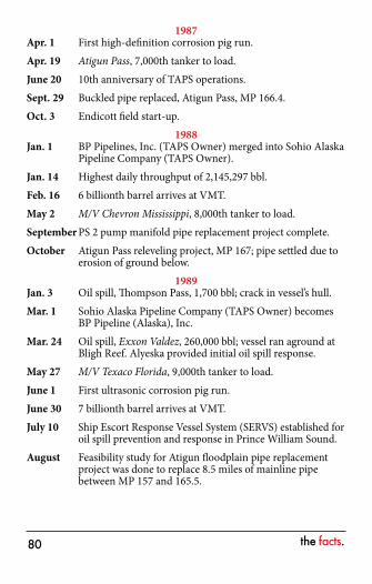
1987Apr. 1 First high-definition corrosion pig run.Apr. 19 Atigun Pass, 7,000th tanker to load.June 20 10th anniversary of TAPS operations.Sept. 29 Buckled pipe replaced, Atigun Pass, MP 166.4.Oct. 3 Endicott field start-up.
1988Jan. 1 BP Pipelines, Inc. (TAPS Owner) merged into Sohio Alaska
Pipeline Company (TAPS Owner).Jan. 14 Highest daily throughput of 2,145,297 bbl.Feb. 16 6 billionth barrel arrives at VMT.May 2 M/V Chevron Mississippi, 8,000th tanker to load.September PS 2 pump manifold pipe replacement project complete.October Atigun Pass releveling project, MP 167; pipe settled due to
erosion of ground below.1989
Jan. 3 Oil spill, Thompson Pass, 1,700 bbl; crack in vessel’s hull.Mar. 1 Sohio Alaska Pipeline Company (TAPS Owner) becomes
BP Pipeline (Alaska), Inc.Mar. 24 Oil spill, Exxon Valdez, 260,000 bbl; vessel ran aground at
Bligh Reef. Alyeska provided initial oil spill response.May 27 M/V Texaco Florida, 9,000th tanker to load.June 1 First ultrasonic corrosion pig run.June 30 7 billionth barrel arrives at VMT.July 10 Ship Escort Response Vessel System (SERVS) established for
oil spill prevention and response in Prince William Sound.August Feasibility study for Atigun floodplain pipe replacement
project was done to replace 8.5 miles of mainline pipe between MP 157 and 165.5.

the facts.��
1990Feb. 8 Alyeska and Regional Citizens’ Advisory Council (RCAC)
signed contract.June Construction complete on VMT incinerator repair project.June 12 Deadleg repair/replacement, PS 1.July 31 M/V Exxon New Orleans, 10,000th tanker to load.Aug. 25 1,000th SERVS escort.September PS 3 corrosion repair; station temporarily bypassed.September Construction begins on 8.5-mile Atigun Floodplain Pipe
Replacement Project.Sept. 15 Project to inspect, recoat, and reinsulate 1,600 feet of
insulated buried mainline pipe between MP 167.3 and 167.5 completed.
December First shipment of pipe for Atigun floodplain pipe replacement project arrives in Valdez.
1991Jan. 1 8 billionth barrel arrives at VMT.Feb. 28 ARCO Pipeline Company (TAPS Owner) becomes ARCO
Transportation Alaska, Inc.March Concrete biological treatment tanks (BTT) placed in
service at VMT.September Atigun floodplain pipe replacement project completed (MP
157-165.5).Oct. 2 M/V Overseas Boston, 11,000th tanker to load.Oct. 14 2,000th SERVS escort.
1992January Floor of crude oil storage Tank 5 at VMT replaced and
cathodic protection installed.April-May Corrosion repairs to 2.5-mile section of pipe in the
Chandalar Shelf.June First run of inertial pipeline pig.June 20 15th anniversary of TAPS operations.
the facts.��
July 7 9 billionth barrel arrives at VMT.July 30 Full-scale aerial dispersant test in Prince William Sound.Aug. 7 RGV 73 uncommanded closure, overpressuring the pipeline.Aug. 25 Ombudsman appointed.September Tank 111 at PS 1 returned to service after bottom
replacement project completed.October Recoating of superstructure for Berths 3 and 4 at
VMT completed.December Completion of new roof for 40,000-square-foot dissolved
air flotation (DAF) building at VMT.Dec. 10 Fuel gas line (north of the Brooks Range) re-leveling
project complete.Dec. 28 M/V ARCO California, 12,000th tanker to load.
1993Jan. 1 3,000th SERVS escort.Jan. 20 Petro Star Refinery on-line in Valdez.March Construction of new tug dock at VMT completed.June PS 10, desalter for pretreating topping unit crude feed put
in service.June PS 9, Mainline Pump No. 3 converted to half-head operation.September Recoating of VMT Berth 5 superstructure completed.October Completion of: inspection, repair and recoating of last
of 10 storage tanks at VMT. This completes the initial inspection of all major storage tanks at VMT.
Dec. 10 Fuel gas line pig launcher installed at MP 34.1994
March Tank 209 at PS 10 leaks 3,500 gallons of residual oil in tank farm.
Mar. 5 10 billionth barrel arrives at VMT.May 13 M/V ARCO Texas, 13,000th tanker to load.June 18 4,000th SERVS escort.

the facts.��
July 5 Alyeska selects method of tanker vapor control at VMT.Sept. 26 TAPS Owners’ assessment of pipeline operations complete.
1995Mar. 9 Valdez Emergency Operations Center/Escort Response
Base opened.Mar. 30 Alyeska employees worked 1 million consecutive hours
without a lost time accident.April Alyeska completes major electrical improvement project
(ANSC) line-wide.May 24 PS 8 topping unit shutdown.Oct. 20 Alyeska and U.S. Department of Interior sign new Alaska
Native Utilization Agreement.Oct. 26 PS 7 idled for maintenance, three months.December Alyeska completed construction on new otter
rehabilitation facility.Dec. 12 11 billionth barrel arrives at VMT.Dec. 31 M/V ARCO Juneau, 14,000th tanker to load.
1996January 5,000th SERVS escort.Apr. 20 Oil leak at CV 92 discovered, 800 bbl released.Apr. 25 CV 92 leak repair begins.June 30 PS 8 placed in ramped down status.July 1 PS 10 topping unit placed in ramped down status.August Pressure pulsations felt in Thompson Pass created by
slackline condition.Sept. 17 Alyeska investigates pipe vibrations near pipeline MP 776.Nov. 27 Alyeska responds to evidence of hydrocarbons detected by
soil probes near MP 776; no spill found.
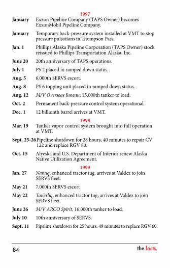
the facts.��
1997January Exxon Pipeline Company (TAPS Owner) becomes
ExxonMobil Pipeline Company.January Temporary back-pressure system installed at VMT to stop
pressure pulsations in Thompson Pass.Jan. 1 Phillips Alaska Pipeline Corporation (TAPS Owner) stock
reissued to Phillips Transportation Alaska, Inc.June 20 20th anniversary of TAPS operations.July 1 PS 2 placed in ramped down status.Aug. 5 6,000th SERVS escort.Aug. 8 PS 6 topping unit placed in ramped down status.Aug. 12 M/V Overseas Juneau, 15,000th tanker to load.Oct. 2 Permanent back-pressure control system operational.Dec. 1 12 billionth barrel arrives at VMT.
1998Mar. 19 Tanker vapor control system brought into full operation
at VMT.Sept. 25-26 Pipeline shutdown for 28 hours, 40 minutes to repair CV
122 and replace RGV 80.Oct. 15 Alyeska and U.S. Department of Interior renew Alaska
Native Utilization Agreement.1999
Jan. 27 Nanuq, enhanced tractor tug, arrives at Valdez to join SERVS fleet.
May 21 7,000th SERVS escortMay 22 Tan’erliq, enhanced tractor tug, arrives at Valdez to join
SERVS fleet.June 26 M/V ARCO Spirit, 16,000th tanker to load.July 10 10th anniversary of SERVS.Sept. 11 Pipeline shutdown for 25 hours, 49 minutes to replace RGV 60.
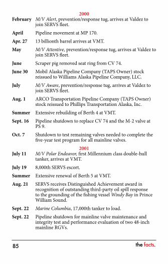
the facts.��
2000February M/V Alert, prevention/response tug, arrives at Valdez to
join SERVS fleet.April Pipeline movement at MP 170.Apr. 27 13 billionth barrel arrives at VMT.May M/V Attentive, prevention/response tug, arrives at Valdez to
join SERVS fleet.June Scraper pig removed seat ring from CV 74.June 30 Mobil Alaska Pipeline Company (TAPS Owner) stock
reissued to Williams Alaska Pipeline Company, LLC.July M/V Aware, prevention/response tug, arrives at Valdez to
join SERVS fleet.Aug. 1 ARCO Transportation Pipeline Company (TAPS Owner)
stock reissued to Phillips Transportation Alaska, Inc.Summer Extensive rebuilding of Berth 4 at VMT.Sept. 16 Pipeline shutdown to replace CV 74 and the M-2 valve at
PS 9.Oct. 7 Shutdown to test remaining valves needed to complete the
five-year test program for all mainline valves.2001
July 11 M/V Polar Endeavor, first Millennium class double-hull tanker, arrives at VMT.
July 19 8,000th SERVS escort.Summer Extensive renewal of Berth 5 at VMT.Aug. 21 SERVS receives Distinguished Achievement award in
recognition of outstanding third-party oil spill response to the grounding of the fishing vessel Windy Bay in Prince William Sound.
Sept. 22 Marine Columbia, 17,000th tanker to load.Sept. 22 Pipeline shutdown for mainline valve maintenance and
integrity test and performance evaluation of two 48-inch mainline RGVs.
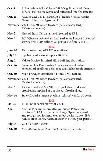
the facts.��
Oct. 4 Bullet hole at MP 400 leaks 258,000 gallons of oil. Over 178,000 gallons recovered and reinjected into the pipeline.
Oct. 25 Alyeska and U.S. Department of Interior renew Alaska Native Utilization Agreement.
November VMT Tank 94 raised two feet (ballast water tank, 250-foot diameter).
Nov. 2 First oil from Northstar field received at PS 1.Nov. 9 M/V Chevron Mississippi, final tanker load after 30 years of
service and 1,002 sailings, all ports (432 from VMT).2002
June 20 25th anniversary of TAPS operations.July 25 Pipeline shutdown to replace RGV 39.Aug. 1 Valdez Marine Terminal office building dedication.Oct. 10 Laden tanker Kenai assisted by escort vessels when
mechanical problems developed at Hinchinbrook Entrance.Oct. 30 Main firewater distribution line at VMT relined.November VMT Tank 93 raised two feet (ballast water tank,
250-foot diameter).Nov. 3 7.9 earthquake at MP 588; damaged shoes and VSM
crossbeams repaired and replaced. No oil spilled.Nov. 26 State of Alaska renews pipeline right-of-way for 30 years.
2003Jan. 20 14 billionth barrel arrives at VMT.April Alyeska Pipeline receives the American Petroleum
Institute’s 2002 Environmental Large Operator Award and recognition for improved safety performance (29% reduction in OSHA recordables over a three-year period).
July 23 9,000th SERVS escort.Oct. 10 M/V Marine Columbia, 18,000th tanker to load.

the facts.�7
2004April Alyeska Pipeline receives the American Petroleum
Institute’s 2003 Environmental Large Operator Award and recognition for improved safety performance (47% reduction in OSHA recordables over a three-year period).
2005April Alyeska Pipeline receives the American Petroleum
Institute’s 2004 Environmental Large Operator Award (no Pipeline Performance Tracking System (PPTS) releases).
Dec. 14 10,000th SERVS escort.Dec. 21 15 billionth barrel arrives at VMT.
2006April Alyeska wins the American Petroleum Institute’s
Distinguished Environmental and Safety Award. This is the API’s highest recognition for a pipeline operator. Alyeska also received the 2005 Environmental Large Operator Award (zero releases).
August Smart Pig run from PS 1 to PS 4, successful.September Smart Pig run from PS 4 to VMT, not successful due to wax
build up. Rerun scheduled for March 2007.Dec. 22 Scraper Pig 67 came apart in line at PS 7
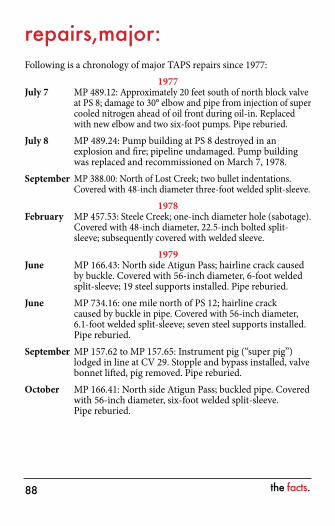
the facts.��
repairs,major: Following is a chronology of major TAPS repairs since 1977:
1977July 7 MP 489.12: Approximately 20 feet south of north block valve
at PS 8; damage to 30° elbow and pipe from injection of super cooled nitrogen ahead of oil front during oil-in. Replaced with new elbow and two six-foot pumps. Pipe reburied.
July 8 MP 489.24: Pump building at PS 8 destroyed in an explosion and fire; pipeline undamaged. Pump building was replaced and recommissioned on March 7, 1978.
September MP 388.00: North of Lost Creek; two bullet indentations. Covered with 48-inch diameter three-foot welded split-sleeve.
1978February MP 457.53: Steele Creek; one-inch diameter hole (sabotage).
Covered with 48-inch diameter, 22.5-inch bolted split-sleeve; subsequently covered with welded sleeve.
1979June MP 166.43: North side Atigun Pass; hairline crack caused
by buckle. Covered with 56-inch diameter, 6-foot welded split-sleeve; 19 steel supports installed. Pipe reburied.
June MP 734.16: one mile north of PS 12; hairline crack caused by buckle in pipe. Covered with 56-inch diameter, 6.1-foot welded split-sleeve; seven steel supports installed. Pipe reburied.
September MP 157.62 to MP 157.65: Instrument pig (“super pig”) lodged in line at CV 29. Stopple and bypass installed, valve bonnet lifted, pig removed. Pipe reburied.
October MP 166.41: North side Atigun Pass; buckled pipe. Covered with 56-inch diameter, six-foot welded split-sleeve. Pipe reburied.
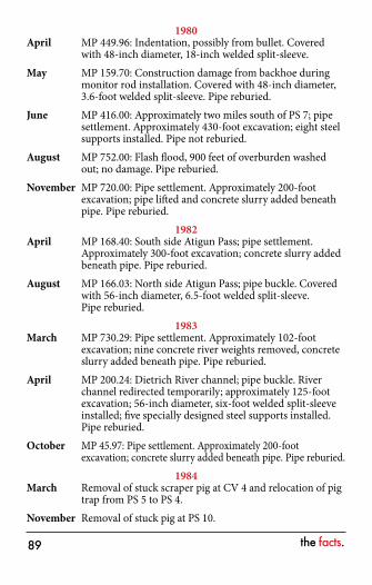
the facts.��
1980April MP 449.96: Indentation, possibly from bullet. Covered
with 48-inch diameter, 18-inch welded split-sleeve.May MP 159.70: Construction damage from backhoe during
monitor rod installation. Covered with 48-inch diameter, 3.6-foot welded split-sleeve. Pipe reburied.
June MP 416.00: Approximately two miles south of PS 7; pipe settlement. Approximately 430-foot excavation; eight steel supports installed. Pipe not reburied.
August MP 752.00: Flash flood, 900 feet of overburden washed out; no damage. Pipe reburied.
November MP 720.00: Pipe settlement. Approximately 200-foot excavation; pipe lifted and concrete slurry added beneath pipe. Pipe reburied.
1982April MP 168.40: South side Atigun Pass; pipe settlement.
Approximately 300-foot excavation; concrete slurry added beneath pipe. Pipe reburied.
August MP 166.03: North side Atigun Pass; pipe buckle. Covered with 56-inch diameter, 6.5-foot welded split-sleeve. Pipe reburied.
1983March MP 730.29: Pipe settlement. Approximately 102-foot
excavation; nine concrete river weights removed, concrete slurry added beneath pipe. Pipe reburied.
April MP 200.24: Dietrich River channel; pipe buckle. River channel redirected temporarily; approximately 125-foot excavation; 56-inch diameter, six-foot welded split-sleeve installed; five specially designed steel supports installed. Pipe reburied.
October MP 45.97: Pipe settlement. Approximately 200-foot excavation; concrete slurry added beneath pipe. Pipe reburied.
1984March Removal of stuck scraper pig at CV 4 and relocation of pig
trap from PS 5 to PS 4.November Removal of stuck pig at PS 10.
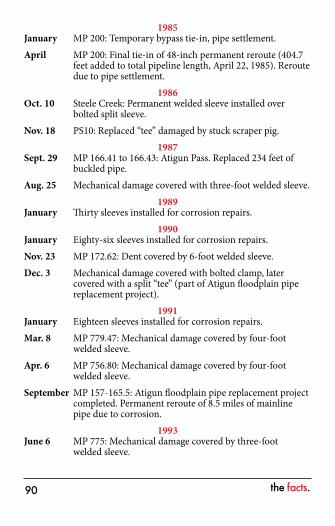
the facts.�0
1985January MP 200: Temporary bypass tie-in, pipe settlement.April MP 200: Final tie-in of 48-inch permanent reroute (404.7
feet added to total pipeline length, April 22, 1985). Reroute due to pipe settlement.
1986Oct. 10 Steele Creek: Permanent welded sleeve installed over
bolted split sleeve.Nov. 18 PS10: Replaced “tee” damaged by stuck scraper pig.
1987Sept. 29 MP 166.41 to 166.43: Atigun Pass. Replaced 234 feet of
buckled pipe.Aug. 25 Mechanical damage covered with three-foot welded sleeve.
1989January Thirty sleeves installed for corrosion repairs.
1990January Eighty-six sleeves installed for corrosion repairs.Nov. 23 MP 172.62: Dent covered by 6-foot welded sleeve.Dec. 3 Mechanical damage covered with bolted clamp, later
covered with a split “tee” (part of Atigun floodplain pipe replacement project).
1991January Eighteen sleeves installed for corrosion repairs.Mar. 8 MP 779.47: Mechanical damage covered by four-foot
welded sleeve.Apr. 6 MP 756.80: Mechanical damage covered by four-foot
welded sleeve.September MP 157-165.5: Atigun floodplain pipe replacement project
completed. Permanent reroute of 8.5 miles of mainline pipe due to corrosion.
1993June 6 MP 775: Mechanical damage covered by three-foot
welded sleeve.
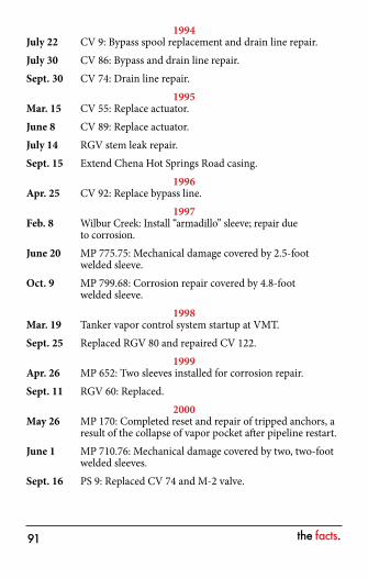
the facts.��
1994July 22 CV 9: Bypass spool replacement and drain line repair.July 30 CV 86: Bypass and drain line repair.Sept. 30 CV 74: Drain line repair.
1995Mar. 15 CV 55: Replace actuator.June 8 CV 89: Replace actuator.July 14 RGV stem leak repair.Sept. 15 Extend Chena Hot Springs Road casing.
1996Apr. 25 CV 92: Replace bypass line.
1997Feb. 8 Wilbur Creek: Install “armadillo” sleeve; repair due
to corrosion.June 20 MP 775.75: Mechanical damage covered by 2.5-foot
welded sleeve.Oct. 9 MP 799.68: Corrosion repair covered by 4.8-foot
welded sleeve.1998
Mar. 19 Tanker vapor control system startup at VMT.Sept. 25 Replaced RGV 80 and repaired CV 122.
1999Apr. 26 MP 652: Two sleeves installed for corrosion repair.Sept. 11 RGV 60: Replaced.
2000May 26 MP 170: Completed reset and repair of tripped anchors, a
result of the collapse of vapor pocket after pipeline restart.June 1 MP 710.76: Mechanical damage covered by two, two-foot
welded sleeves.Sept. 16 PS 9: Replaced CV 74 and M-2 valve.
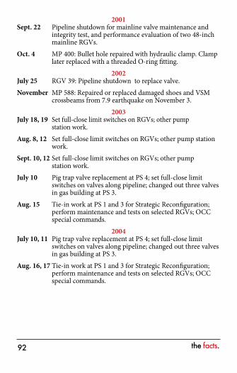
the facts.��
2001Sept. 22 Pipeline shutdown for mainline valve maintenance and
integrity test, and performance evaluation of two 48-inch mainline RGVs.
Oct. 4 MP 400: Bullet hole repaired with hydraulic clamp. Clamp later replaced with a threaded O-ring fitting.
2002July 25 RGV 39: Pipeline shutdown to replace valve.November MP 588: Repaired or replaced damaged shoes and VSM
crossbeams from 7.9 earthquake on November 3.2003
July 18, 19 Set full-close limit switches on RGVs; other pump station work.
Aug. 8, 12 Set full-close limit switches on RGVs; other pump station work.
Sept. 10, 12 Set full-close limit switches on RGVs; other pump station work.
July 10 Pig trap valve replacement at PS 4; set full-close limit switches on valves along pipeline; changed out three valves in gas building at PS 3.
Aug. 15 Tie-in work at PS 1 and 3 for Strategic Reconfiguration; perform maintenance and tests on selected RGVs; OCC special commands.
2004July 10, 11 Pig trap valve replacement at PS 4; set full-close limit
switches on valves along pipeline; changed out three valves in gas building at PS 3.
Aug. 16, 17 Tie-in work at PS 1 and 3 for Strategic Reconfiguration; perform maintenance and tests on selected RGVs; OCC special commands.
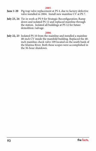
the facts.��
2005June 1-20 Pig trap valve replacement at PS 4, due to factory defective
valve installed in 2004. Install new mainline CV at PS 7. July 23, 24 Tie-in work at PS 9 for Strategic Reconfiguration; Ramp
down and isolated PS 12 and replaced mainline through the station. Isolated all buildings at PS 12 for future demolition /salvage.
2006July 22, 23 Isolated PS 10 from the mainline and installed a mainline
48-inch CV inside the manifold building. Replaced the 48-inch mainline check valve 109 located on the south bank of the Klutina River. Both these scopes were accomplished in the 36-hour shutdown.
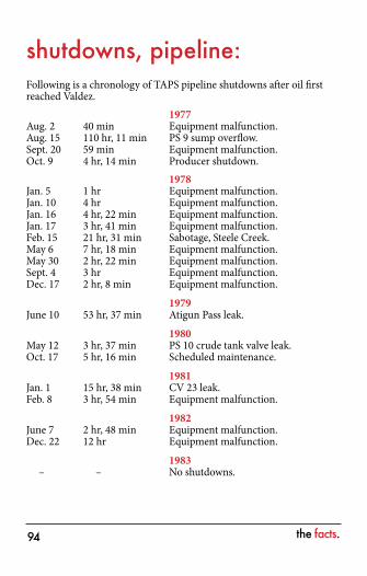
the facts.��
shutdowns, pipeline: Following is a chronology of TAPS pipeline shutdowns after oil first reached Valdez. 1977Aug. 2 40 min Equipment malfunction.Aug. 15 110 hr, 11 min PS 9 sump overflow.Sept. 20 59 min Equipment malfunction.Oct. 9 4 hr, 14 min Producer shutdown. 1978Jan. 5 1 hr Equipment malfunction.Jan. 10 4 hr Equipment malfunction.Jan. 16 4 hr, 22 min Equipment malfunction.Jan. 17 3 hr, 41 min Equipment malfunction.Feb. 15 21 hr, 31 min Sabotage, Steele Creek.May 6 7 hr, 18 min Equipment malfunction.May 30 2 hr, 22 min Equipment malfunction.Sept. 4 3 hr Equipment malfunction.Dec. 17 2 hr, 8 min Equipment malfunction.
1979June 10 53 hr, 37 min Atigun Pass leak. 1980May 12 3 hr, 37 min PS 10 crude tank valve leak.Oct. 17 5 hr, 16 min Scheduled maintenance. 1981Jan. 1 15 hr, 38 min CV 23 leak.Feb. 8 3 hr, 54 min Equipment malfunction. 1982June 7 2 hr, 48 min Equipment malfunction.Dec. 22 12 hr Equipment malfunction. 1983 – – No shutdowns.
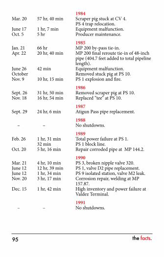
the facts.��
1984Mar. 20 57 hr, 40 min Scraper pig stuck at CV 4. PS 4 trap relocation.June 17 1 hr, 7 min Equipment malfunction.Oct. 5 5 hr Producer maintenance. 1985Jan. 21 66 hr MP 200 by-pass tie-in.Apr. 22 20 hr, 40 min MP 200 final reroute tie-in of 48-inch
pipe (404.7 feet added to total pipeline length).
June 26 42 min Equipment malfunction.October Removed stuck pig at PS 10.Nov. 9 10 hr, 15 min PS 1 explosion and fire. 1986Sept. 26 31 hr, 50 min Removed scraper pig at PS 10.Nov. 18 16 hr, 54 min Replaced “tee” at PS 10. 1987Sept. 29 24 hr, 6 min Atigun Pass pipe replacement. 1988 – – No shutdowns. 1989Feb. 26 1 hr, 31 min Total power failure at PS 1. 32 min PS 1 block line.Oct. 20 5 hr, 16 min Repair corroded pipe at MP 144.2. 1990Mar. 21 4 hr, 10 min PS 3, broken nipple valve 320.June 12 12 hr, 39 min PS 1, valve D2 pipe replacement.June 12 1 hr, 34 min PS 9 isolated station, valve M2 leak.Nov. 20 3 hr, 17 min Corrosion repair, welding at MP
157.87.Dec. 15 1 hr, 42 min High inventory and power failure at
Valdez Terminal. 1991 – – No shutdowns.
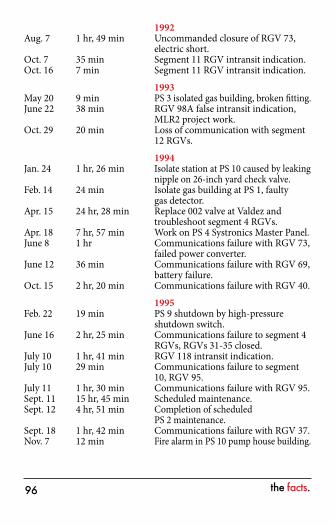
the facts.��
1992Aug. 7 1 hr, 49 min Uncommanded closure of RGV 73,
electric short.Oct. 7 35 min Segment 11 RGV intransit indication.Oct. 16 7 min Segment 11 RGV intransit indication. 1993May 20 9 min PS 3 isolated gas building, broken fitting.June 22 38 min RGV 98A false intransit indication,
MLR2 project work.Oct. 29 20 min Loss of communication with segment
12 RGVs. 1994Jan. 24 1 hr, 26 min Isolate station at PS 10 caused by leaking
nipple on 26-inch yard check valve.Feb. 14 24 min Isolate gas building at PS 1, faulty
gas detector.Apr. 15 24 hr, 28 min Replace 002 valve at Valdez and
troubleshoot segment 4 RGVs.Apr. 18 7 hr, 57 min Work on PS 4 Systronics Master Panel.June 8 1 hr Communications failure with RGV 73,
failed power converter.June 12 36 min Communications failure with RGV 69,
battery failure.Oct. 15 2 hr, 20 min Communications failure with RGV 40. 1995Feb. 22 19 min PS 9 shutdown by high-pressure
shutdown switch.June 16 2 hr, 25 min Communications failure to segment 4
RGVs, RGVs 31-35 closed.July 10 1 hr, 41 min RGV 118 intransit indication.July 10 29 min Communications failure to segment
10, RGV 95.July 11 1 hr, 30 min Communications failure with RGV 95.Sept. 11 15 hr, 45 min Scheduled maintenance.Sept. 12 4 hr, 51 min Completion of scheduled
PS 2 maintenance.Sept. 18 1 hr, 42 min Communications failure with RGV 37.Nov. 7 12 min Fire alarm in PS 10 pump house building.
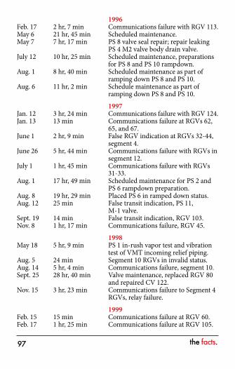
the facts.�7
1996Feb. 17 2 hr, 7 min Communications failure with RGV 113.May 6 21 hr, 45 min Scheduled maintenance.May 7 7 hr, 17 min PS 8 valve seal repair; repair leaking
PS 4 M2 valve body drain valve.July 12 10 hr, 25 min Scheduled maintenance, preparations
for PS 8 and PS 10 rampdown.Aug. 1 8 hr, 40 min Scheduled maintenance as part of
ramping down PS 8 and PS 10.Aug. 6 11 hr, 2 min Schedule maintenance as part of
ramping down PS 8 and PS 10. 1997Jan. 12 3 hr, 24 min Communications failure with RGV 124.Jan. 13 13 min Communications failure at RGVs 62,
65, and 67.June 1 2 hr, 9 min False RGV indication at RGVs 32-44,
segment 4.June 26 5 hr, 44 min Communications failure with RGVs in
segment 12.July 1 1 hr, 45 min Communications failure with RGVs
31-33.Aug. 1 17 hr, 49 min Scheduled maintenance for PS 2 and
PS 6 rampdown preparation.Aug. 8 19 hr, 29 min Placed PS 6 in ramped down status.Aug. 12 25 min False transit indication, PS 11,
M-1 valve.Sept. 19 14 min False transit indication, RGV 103.Nov. 8 1 hr, 17 min Communications failure, RGV 45. 1998May 18 5 hr, 9 min PS 1 in-rush vapor test and vibration
test of VMT incoming relief piping.Aug. 5 24 min Segment 10 RGVs in invalid status.Aug. 14 5 hr, 4 min Communications failure, segment 10.Sept. 25 28 hr, 40 min Valve maintenance, replaced RGV 80
and repaired CV 122.Nov. 15 3 hr, 23 min Communications failure to Segment 4
RGVs, relay failure. 1999Feb. 15 15 min Communications failure at RGV 60.Feb. 17 1 hr, 25 min Communications failure at RGV 105.
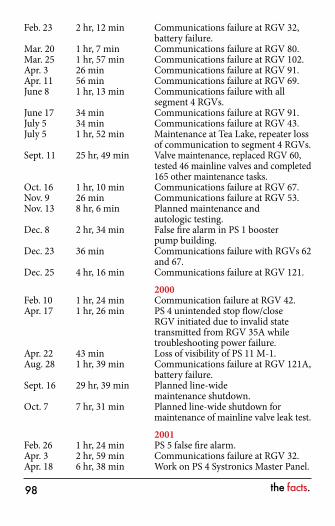
the facts.��
Feb. 23 2 hr, 12 min Communications failure at RGV 32, battery failure.
Mar. 20 1 hr, 7 min Communications failure at RGV 80.Mar. 25 1 hr, 57 min Communications failure at RGV 102.Apr. 3 26 min Communications failure at RGV 91.Apr. 11 56 min Communications failure at RGV 69.June 8 1 hr, 13 min Communications failure with all
segment 4 RGVs.June 17 34 min Communications failure at RGV 91.July 5 34 min Communications failure at RGV 43.July 5 1 hr, 52 min Maintenance at Tea Lake, repeater loss
of communication to segment 4 RGVs.Sept. 11 25 hr, 49 min Valve maintenance, replaced RGV 60,
tested 46 mainline valves and completed 165 other maintenance tasks.
Oct. 16 1 hr, 10 min Communications failure at RGV 67.Nov. 9 26 min Communications failure at RGV 53.Nov. 13 8 hr, 6 min Planned maintenance and
autologic testing.Dec. 8 2 hr, 34 min False fire alarm in PS 1 booster
pump building.Dec. 23 36 min Communications failure with RGVs 62
and 67.Dec. 25 4 hr, 16 min Communications failure at RGV 121. 2000Feb. 10 1 hr, 24 min Communication failure at RGV 42.Apr. 17 1 hr, 26 min PS 4 unintended stop flow/close
RGV initiated due to invalid state transmitted from RGV 35A while troubleshooting power failure.
Apr. 22 43 min Loss of visibility of PS 11 M-1.Aug. 28 1 hr, 39 min Communications failure at RGV 121A,
battery failure.Sept. 16 29 hr, 39 min Planned line-wide
maintenance shutdown.Oct. 7 7 hr, 31 min Planned line-wide shutdown for
maintenance of mainline valve leak test. 2001Feb. 26 1 hr, 24 min PS 5 false fire alarm.Apr. 3 2 hr, 59 min Communications failure at RGV 32.Apr. 18 6 hr, 38 min Work on PS 4 Systronics Master Panel.
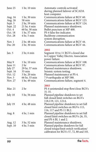
the facts.��
June 25 1 hr, 10 min Automatic controls activated during planned failover of SCADA host computer.
Aug. 16 1 hr, 30 min Communications failure at RGV 60.Aug. 26 58 min Communications failure at RGV 123.Sept. 5 2 hr, 59 min Communications failure at RGV 124.Sept. 22 21 hr, 4 min Planned maintenance shutdown.Oct. 4 60 hr, 30 min Bullet puncture at MP 400.Oct. 18 1 hr, 57 min PS 4 false fire indicator.Oct. 28 4 hr, 5 min Backbone communication
system disruption.Nov. 1 2 hr, 48 min Communications failure at RGV 44.Dec 20 2 hr, 30 min Communications failure at RGV 44. 2002Jan. 5 2 hr, 6 min Segment 10 to 11 RGVs closed due
to Copper Valley Electric Association power failure.
May 9 1 hr, 10 min Communications failure at RGV 108.June 11 2 hr Communications failure at RGV 97.July 27 29 hr, 57 min Planned maintenance shutdown.Sept. 16 35 min Seismic system testing.Oct. 12 3 hr, 20 min Planned maintenance at PS 4.Nov. 3 66 hr, 33 min 7.9 earthquake at MP 588.Nov. 27 1 hr, 49 min Communications failure, segment 4. 2003Mar. 21 2 hr PS 4 unintended stop flow/close RGVs
31-35.July 18 5 hr, 56 min Planned pipeline shutdown to set
full closed limit switches on RGVs 118,119, 121, 121A.
July 19 4 hr, 48 min Planned pipeline shutdown to set full closed limit switches on RGVs 115, 116, 117 and PS 11 BL2.
Aug. 8 4 hr, 1 min Planned pipeline shutdown to set full closed limit switches on RGVs 26, 35, and PS 4 BL 1 and 2.
Aug. 12 3 hr, 52 min Planned maintenance shutdown. Sept. 10 4 hr, 5 min Planned pipeline shutdown for full
closed torque/limit switch verification/ calibration for RGVs 57, 72, 88 and 101.
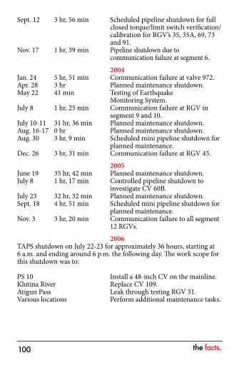
the facts.�00
Sept. 12 3 hr, 56 min Scheduled pipeline shutdown for full closed torque/limit switch verification/calibration for RGV’s 35, 35A, 69, 73 and 91.
Nov. 17 1 hr, 39 min Pipeline shutdown due to communication failure at segment 6.
2004Jan. 24 5 hr, 51 min Communication failure at valve 972.Apr. 28 3 hr Planned maintenance shutdown.May 22 41 min Testing of Earthquake
Monitoring System.July 8 1 hr, 25 min Communication failure at RGV in
segment 9 and 10.July 10-11 31 hr, 36 min Planned maintenance shutdown.Aug. 16-17 0 hr Planned maintenance shutdown.Aug. 30 3 hr, 9 min Scheduled mini pipeline shutdown for
planned maintenance.Dec. 26 3 hr, 31 min Communication failure at RGV 45. 2005June 19 35 hr, 42 min Planned maintenance shutdown.July 8 1 hr, 17 min Controlled pipeline shutdown to
investigate CV 60B.July 23 32 hr, 32 min Planned maintenance shutdown.Sept. 18 4 hr, 51 min Scheduled mini pipeline shutdown for
planned maintenance.Nov. 3 3 hr, 20 min Communication failure to all segment
12 RGVs. 2006TAPS shutdown on July 22-23 for approximately 36 hours, starting at 6 a.m. and ending around 6 p.m. the following day. The work scope for this shutdown was to:
PS 10 Install a 48-inch CV on the mainline.Klutina River Replace CV 109.Atigun Pass Leak through testing RGV 31.Various locations Perform additional maintenance tasks.
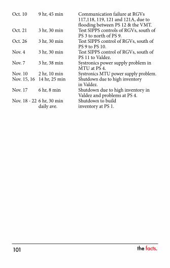
the facts.�0�
Oct. 10 9 hr, 45 min Communication failure at RGVs 117,118, 119, 121 and 121A, due to flooding between PS 12 & the VMT.
Oct. 21 3 hr, 30 min Test SIPPS controls of RGVs, south of PS 3 to north of PS 9.
Oct. 26 3 hr, 30 min Test SIPPS control of RGVs, south of PS 9 to PS 10.
Nov. 4 3 hr, 30 min Test SIPPS control of RGVs, south of PS 11 to Valdez.
Nov. 7 3 hr, 38 min Systronics power supply problem in MTU at PS 4.
Nov. 10 2 hr, 10 min Systronics MTU power supply problem.Nov. 15, 16 14 hr, 25 min Shutdown due to high inventory
in Valdez.Nov. 17 6 hr, 8 min Shutdown due to high inventory in
Valdez and problems at PS 4.Nov. 18 - 22 6 hr, 30 min Shutdown to build daily ave. inventory at PS 1.

the facts.�0�
notes

the facts.�0�