the-eye.euthe-eye.eu/public/books/survival_guide/weaving/tappet_and_dobby_looms_1912.pdfuniformwiththisvolume...
TRANSCRIPT
^FETy

LIBRARY
^^ssACtft;^^^
1895

O^^"'^%^

TEXTILE MANUFACTURER'' MANUALS
TAPPET AND DOBBY LOOMSTHEIR MECHANISM AND MANAGEMENT
UNIFORM WITH THIS VOLUME
THEORY OF SIZINGBy H. NISBET
Treating of the essential constituents and properties
of Sizing Ingredients, and the chief factors determining
the selecting, blending and mixing of those ingredients
suitably to the requirements of manufacturers and
merchants of Textile Fabrics.
"... The author has presented in quite a small compass aboutall the essential points connected with sizing necessary for the
student of the subject and the practitioner, which should makeit more acceptable than some of the more pretentious but less
practical works which have hitherto appeared."
—
The TextileMercury.
Illustrated. 2/6 net
PRODUCTIVE COSTSIN COTTON SPINNING MILLS
By ARTHUR H. HARDMANAn endeavour to evolve, from the divers methods of
costing which are practised in the trade to-day, a com-
plete system of cotton yarn costing, which shall, on the
one side, be sound from an accountancy point of view,
having its basis in the account books of the concern;
and, on the other, be sufficiently practical to take into
consideration all the details and problems of the pro-
cesses of manufacture, so far as they affect the cost of
the product.
" Mr Hardman is so clear, both in diagram and in the text,
that it is perfectly understandable by the veriest layman, andyet, at the same time, one realises how important such a text-
book must be to the successful cotton spinner." — YorkshireFactory Times.
119 pages. With numerous Tables and Diagrams. 3/6 net
Manchester : EMMOTT & CO., LIMITED, 65 King Stkeet
London ; 20 Bedford Street, W.C.
Tappet and Dobby
Looms :
THEIR MECHANISM AND MANAGEMENT
p CD (~) p p R "TV O i
•
THOMAS ROBERTSHead of the Weaving and Designing Departments
OF THE HOLMFIRTH AND DevVSBURY TECHNICALInstitutes, and formerly Lecturer
IN the Textile DepartmentOF THE HuDDERSFIELDTechnical College
MANCHESTEREMMOTT &C0., LIMITED
65 KING STREET
LONDON : 20 BEDFORD STREET, W.C
1912
[J// Rights Reserved]

US
PREFACE
The object of this work— the greater portion of
which originally appeared as a series of articles in
T/ie Textile Manufacturer—is to help those who are
engaged in the weaving industry to obtain a fuller
knowledge of the mechanism and management of
the loom. At the same time it is hoped that the
book will supply a much - needed addition to the
scanty literature at present available on this par-
ticular branch of the manufacturing processes.
A special feature of the subject-matter is the
references to defects produced in fabrics during
weaving, these being drawn from observations madeby the author during his many years' practical ex-
perience of the subject.
The illustrations employed to elucidate the con-
struction of the various motions are chiefly line
drawings—drawn to scale—from well-known types
of looms. The detailed descriptions of the motions
have been expressly included for the sake of students
following out a course of technical instruction—the
author, as a teacher of textile technology, having
experienced a long-felt want in this particular
direction.
Thomas Roberts.
Huddp:rsfield, April 191 2.
7/

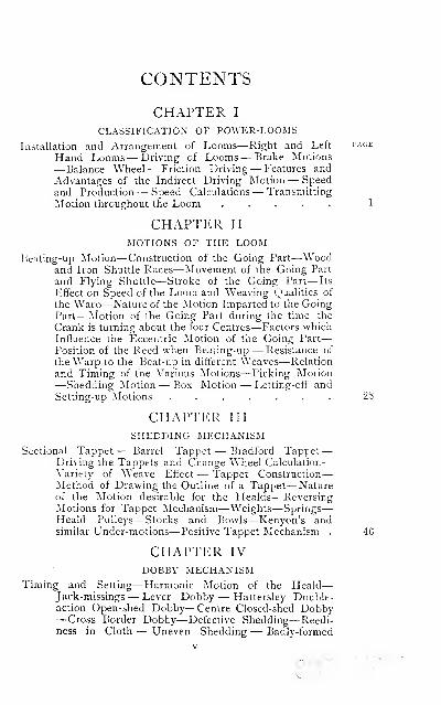
CONTENTS
CHAPTER I
CLASSIFICATION OF POWER-LOOMS
Installation and Arrangement of Looms—Right and Left page
Hand Looms— Driving of Looms— Brake Motions
— Balance Wheel— Friction Driving— Features and
Advantages of the Indirect Driving Motion — Speedand Production — Speed Calculations — Transmitting
Motion throughout the Loom ..... 1
CHAPTER nxMOTIONS OF THE LOOM
Beating-up Motion—Construction of the Going Part—Woodand Iron Shuttle Races—Movement of the Going Part
and Flying Shuttle—Stroke of the Going Part— Its
Effect on Speed of the Loom and Weaving Qualities of
the Warp—Nature of the Motion Imparted to the GoingPart—Motion of the Going Part during the time the
Crank is turning about the four Centres—Factors whichInfluence the Eccentric Motion of the Going Part
—
Position of the Reed when Beating-up — Resistance of
the Warp to the Beat-up in different Weaves—Relation
and Timing of the Various Motions—Picking Motion—Shedding Motion — Box Motion — Letting-oft' andSetting-up Motions ....... 28
CHAPTER III
SHEDDING MECHANISMSectional Tappet — Barrel Tappet — Bradford Tappet—
Driving the Tappets and Change Wheel Calculation
—
Variety of Weave Effect — Tappet Construction
—
Method of Drawing the Outline of a Tappet— Nature' of the Motion desirable for the Healds—Reversing
Motions for Tappet Mechanism—Weights—Springs
—
Heald Pulleys—Stocks and Bowls—Kenyon's andsimilar Under-motions—Positive Tappet Mechanism . 46
CHAPTER IV
DOBBY MECHANISMTiming and Setting—Harmonic Motion of the Heald
—
Jack-missings— Lever Dobby — Hattersley Double-action Open-shed Dobby— Centre Closed-shed Dobby—Cross Border Dobby—Defective Shedding— Reedi-ness in Cloth — Uneven Shedding— Badly-formed
mil
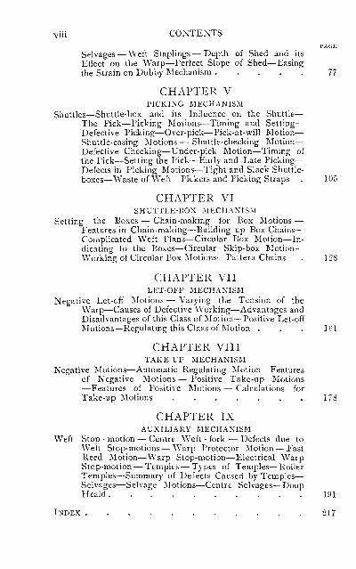
viii CONTENTSPAGE
Selvages— Weft Staplings— Depth of Shed and its
Effect on the Warp—Perfect Slope of Shed—Easing
the Strain on Dobby Mechanism , . . . . 77
CHAPTER VPICKING MECHANISM
Shuttles—Shuttle-box and its Influence on the Shuttle
—
The Pick—Picking Motions—Timing and Setting
—
Defective Picking—Over-pick— Pick-at-will Motion
—
Shuttle-easing Motions — Shuttle-checking Motion
—
Defective Checking—Under-pick Motion—Timing of
the Pick—Setting the Pick—Early and Late Picking
—
Defects in Picking Motions—Tight and Slack Shuttle-
boxes—Waste of Weft—Pickers and Picking Straps . 105
CHAPTER VISHUTTLE-BOX MECHANISM
Setting the Boxes — Chain-making for Box Motions —Features in Chain-making—Building up Box Chains
—
Complicated Weft Plans— Circular Box Motion—In-
dicating to the Boxes— Circular Skip-box Motion
—
Working of Circular Box Motions—Pattern Chains . 128
CHAPTER VllLET-OFF MECHANISM
Negative Let-ofif Motions — Varying the Tension of the
Warp—Causes of Defective Working—Advantages andDisadvantages of this Class of Motion—Positive Let-off
Motions—Regulating this Class of Motion . . . 161
CHAPTER VIIITAKE-UP MECHANISM
Negative Motions—Automatic Regulating Motion— Features
of Negative Motions — Positive Take-up Motions—Features of Positive Motions — Calculations for
Take-up Motions 178
CHAPTER IXAUXILIARY MECHANISM
Weft Stop - motion — Centre Weft - fork — Defects due to
Weft Stop-motions— Warp Protector Motion— FastReed Motion—Warp Stop-motion— Electrical WarpStop-motion— Temples— Types of Temples— RollerTemples—Summary of Defects Caused by Temples
—
Selvages—Selvage Motions—Centre Selvages—DoupHeald 191
Index 217
TAPPET AND DOBBYLOOMS
THEIR MECHANISM AND MANAGEMENT
CHAPTER I
CLASSIFICATION OF POWER-LOOMS
Looms may be divided into three classes — namely,
(a) tappet, (b) dobby, and (c) jacquard looms. Other
methods of classification are sometimes adopted
—
e.g.,
according to the class of fabric for which the looms are
specially adapted, as light goods tappet loom, heavy
woollen loom, fancy coating box loom, and fancy cotton
dobby loom; whilst they are also referred to by the
name of the maker or place of manufacture. It will be
evident, from the many terms of classification, that no
definite line of demarcation can be drawn, although in
some districts one style or class of loom preponderates.
The most general method in vogue is that which differen-
tiates according to the style of the shedding motion
employed.
Tappet looms are so named by reason of the mechanism
employed to control the healds. This class includes the
plain loom fitted with inside tappets to take from two
to eight heald shafts, or with outside tappets to accom-
A I
2 TAPPET AND DOBBY LOOMS
modate up to twelve shafts. The latter type of loom is
often styled the Bradford tappet loom, as it is largel}^
used in that district. The plain loom fitted with the
Woodcroft and other styles of tappets is also included
in this class. Many tappet looms are mounted with
boxes, usually circular boxes, at one or both sides.
Generally speaking, such looms are employed to weave
calico, plain dress goods, Hnings, plain coatings, serges,
meltons, beavers—in short, any class of fabric which
does not require a large number of healds, and in which
the weave is complete on not more than 12 picks. Dobbylooms are so named on account of the healds being
operated by dobby mechanism, which is entirely differ-
ent in its construction from tappet mechanism. Dobbies
are made to accommodate 48 shafts, but 16, 24, and 36-
shaft dobbies are most common. This class of loom
admits of variety in weave effect, and may yield more
extensive patterns than the tappet loom. It is usually
mounted with a series of boxes at both sides, generally
four, though for weaving certain goods six boxes are
requisite; the loom may also be fitted with two warp
beams. The range of fabrics produced in this loom is
very wide, and includes fancy coatings, trouserings,
fancy dress goods, mantle cloths, cap tweeds, mauds, and
rugs. The term " jacquard looms " has reference to
those looms which are mounted with a jacquard machine.
The advantage of such looms, when compared with the
dobby and tappet looms, is the increased figuring capacity,
as the number of threads which a design may occupy is
practically unlimited. Fabrics of an ornamental and
elaborate character are produced in this loom, of which
fancy vestings, figured dress goods, tapestries, plushes,
and carpets are examples.
Installation and Arrangement of Looms.—Theoperation of weaving, as well as the preparatory pro-
INSTALLATION AND ARRANGEMENT 3
cesses, are such that the room in which they are carried
on should be well lighted. The most suitable building
is a shed with a well-lighted roof, the skylights facing in
a northerly direction, as a more uniform light is then
assured and the direct rays of the sun eliminated. Theroof should be supported by pillars, which also serve to
carry the line shafts. The size of the bays is determined
by the class of loom to be installed. The floor may be
stone, concrete, or wood. If of wood it should be well
supported by piers, these being arranged to come under-
neath the loom feet, a firm foundation being conducive
to satisfactory results, especially if the looms run at
a high speed. Some consideration is essential whenarranging the looms if the most economical conditions
are to be effected. The looms should be placed with
their main or crank shafts at right angles to the skylights,
as this admits of the light falling sideways on the loom,
and consequently prevents any obstruction of light from
the weaver or top rails of the loom when repairing broken
ends, etc.
Right and Left Hand Looms.—To economize driv-
ing power, line shafting, and space, looms are maderight and left hand ; a right-hand loom is one where the
driving belt is on the right-hand side of the weaver whentending the loom, whilst a left-hand loom has the driving
belt on the left-hand side of the weaver. This is the
generally-accepted definition, although occasionally the
side on which the dobby is placed on the loom in relation
to the weaver is employed as the determining factor.
This is more applicable to that type of dobby loom in
which the weaver, when turning the dobby to manipulate
the healds, uses the right hand in a left-hand loom, the
dobby being placed at the opposite end to the driving
belt, and vice versa in the right-hand loom.
When looms are made right and left hand they may be
4 TAPPET AND DOBBY LOOMS
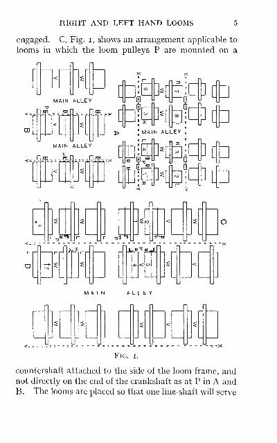
arranged or grouped together in various ways. A, in
Fig. I, shows the ground plan of the arrangement usually
adopted with narrow tappet looms. The looms are
placed in groups of four, one weaver tending each group.
Looms I, 2, 3 and 4 form one group, and looms 5, 6, 7 and
8 form another group. Each group consists of two right-
hand and two left-hand looms, indicated by R and L re-
spectively. The looms are placed with the ends of the
going part close together, leaving a reasonable space
between each group to form the main alley; this latter
should not be too small, but sufficient space allowed to
accommodate skeps and to admit the full warp beams
being run in without any danger of the warps beingbroken.
The amount of space allotted for the weavers' alley W,and also at the back of the looms, should not be too
meagre. This arrangement necessitates only one line-
shaft for two rows of looms. The line-shafts X, Y shown
in dotted lines are overhead behind the looms, and are
carried on pedestals attached to the pihars. A some-
what similar arrangement to the above is sometimes
adopted for looms of a much wider reed space, with the
exception that the looms are grouped in pairs, one weaver
to each pair, with a main alley on each side of the loom,
these being left wider by reason of the increased length
of the warp beams. B, Fig. i, illustrates a commonarrangement practised in relation to looms from 9/4 reed
space and upwards (one quarter equals gin.). These
looms are arranged in pairs with a main alley running
down each side, and with the weavers' alley W and the
back alley V continuous. The main difference between
A and B is the position of the line-shafts X, Y. In the
former the line-shaft is parallel with the crankshafts of
the looms, in the latter it is arranged at right angles.
This method admits of one weaver tending one or two
looms, according to the class of work on which they are
RIGHT AND LEFT HAND LOOMS
engaged. C, Fig. i, shows an arrangement applicable to
looms in which the loom pulleys P are mounted on a
00|_
6 TAPPET AND DOBBY LOOMS
two rows of looms. This is accomplished by bringing
two rows together, leaving a broad alley on each side.
The line-shaft runs parallel with the countershafts of the
looms. Another advantage to be derived from this ar-
rangement is that the weaver's alley W in one row comesopposite to the back alley V of the adjoining rows. This
reduces the dangers due to flying shuttles, as it will be
evident that a shuttle coming out of the alley of loomsNos. I and 2 would travel towards the back alley of
looms Nos. 3 and 4. D, Fig. i, is an alternative arrange-
ment to C. The looms are not arranged in pairs, but are
all either left or right hand. D shows all left-hand (L)
;
consequently one row of weavers would face in the direc-
tion indicated by arrow E, and the adjacent row in the
opposite direction F. If it is desirable that the weaversshould all stand in the same relative position, the looms
would be arranged one row all left-hand and the other
row all right-hand. The advantage claimed for this
system is, that having only one weaver in each alley Wthere is more freedom of action, and each may render
help by tying up the broken warp threads for the weaverimmediately behind.
Driving of Looms.—The general method of driving
power-looms is by means of belts to transmit the motion
from the drums on the line-shafts to the pulleys on the
loom. When the arrangement of the looms is as A, Fig.
I, two looms are driven from the same drum, and in order
to avoid the belts coming together, the looms are placed
so as to allow sufficient working space on the surface of
the drums between the belts, the drums being made wide
enough to allow for this. With one line-shaft driving two
rows of looms, one row is driven by open belts and
the other row by crossed belts; this is due to the
looms being placed on opposite sides of the line-shaft,
and the crankshafts must necessarily revolve in the
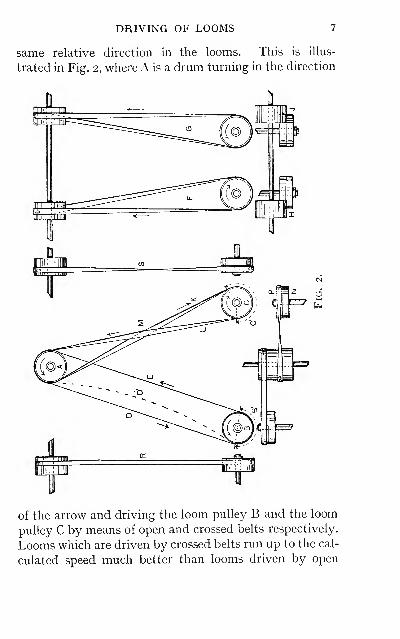
DRIVING OF LOOMS 7
same relative direction in the looms. This is illus-
trated in Fig. 2, where A is a drum turning in the direction
of the arrow and driving the loom pulley B and the loom
pulley C by means of open and crossed belts respectively.
Looms which are driven by crossed belts run up to the cal-
culated speed much better than looms driven by open
8 TAPPET AND DOBBY LOOMS
belts. This is due to the crossed belt encircling more of
the circumference of both the driving and the loom pulley
than is possible with an open belt (compare B^ with C^Fig. 2). The observant tuner will know that the looms
driven by open belts require his attention for reduced speed
and the consequent results, more than looms driven bycrossed belts. The weavers are also aware of this defect,
and attempt to mitigate the evil by applying resin or someother adhesive substance to the belt to prevent it from
slipping. This is an objectionable practice, and should
be discountenanced by the tuner, because when the grip
of the belts is too excessive the loom will have a choppymovement, which is productive of more serious results
—
namely, defective picking, loom knocking-off, imperfect
checking of the shuttle, and shuttle flying out. Asfurther proof of this, the following experiment may be
cited: The tested speed of a loom was five picks per
minute less than the calculated speed; the cause of this
was due to the belt slipping. In preference to tightening
the belt, dressing was applied in such a quantity as would
ensure no further slipping taking place; the loom nowruns at the required speed. The movement of the going
part was then tested by placing the hand lightly on the
slay rail, when an irregular motion could be distinctly
felt. Before the dressing was applied the belt was running
without surging, but afterwards the maximum amountof surging took place, the surging of the belt being re-
sponsible for the erratic movement of the loom. In order
to prevent excessive tensioning of a belt or the applica-
tion of any dressing to maintain the calculated speed,
the writer is of opinion that looms run much better if,
when calculating for the dimensions of the drums, an
increase of 3 to 4 per cent, in speed is allowed above whatis actually required. For instance, if a loom is required
to be run at the rate of 150 picks per minute, the velocity
TIGHT AND SLACK BELTS 9
ratio of the driving drum to the loom pulleys should
work out to a calculated speed of 156 picks per minute.
This method allows the belts to be run somewhat slacker,
and is not attended by any severe strain on the crank-
shaft, or of undue bearing of the crankshaft on the pedestal
in the loom. Under such conditions the belts should be
kept clean, the natural state of the belt being such as wihmaintain the necessary friction on the drums and pulleys.
Looms which are driven by open belts have the following
side, which is the slack part of the belt on the top, as D,
Fig. 2 ; and the pulling side, which is the tight part of the
belt underneath, as E, Fig. 2. The advantage of this
arrangement is that when the belt becomes slack it tends
to occupy a position indicated by the dotted line D^ Fig.
2, and as a consequence the contact of the belt with the
drum and pulley is increased, and the liability of the belt
to slip is reduced.
When looms are arranged with the driving drumsat right angles to the loom pulleys, as at B, Fig. i, the
position of the loom pulleys in relation to the drums needs
careful adjustment or the belts will not work to the best
advantage, and a loss of speed ensues. This is due to the
following side of the belt bearing too heavily on the guide-
fork, and the pulling side of the belt having a tendency to
leave the fast pulley. The relative position of the loompulley to the drum is indicated at F and G, Fig. 2, of a
left and right hand loom respectively. The pulling side
of the belt is practically perpendicular, the approaching
face of the loom pulley being in a vertical plane with the
centre of the surface of the drum as H and J . The follow-
ing side of the belt is conducted back on to the loompulley by the guide-fork. The belts in such an arrange-
ment all work at a quarter twist.
When looms are mounted with a fast-and-loose pulley
driving gear, it is essential that the loom should stop as
10 TAPPET AND DOBBY LOOMS
soon as possible after it is thrown off. The relative position
of the pulling and following sides of a crossed belt to each
other may be arranged to facilitate this—a factor often
overlooked. The following side K of the belt should cross
the pulling side L as at M, as it is then free to run off the
fast pulley N on to the loose pulley P without having to
force its way against the tight side L, and so runs off muchmore quickly and easily.
When the driving motion consists of a loose and fast
pulley, it is not usual to have the full width of the belt on
to the fast pulley when the loom is running, but to
allow a portion to remain on the loose pulley. There
are two reasons for this: First, it affords means for ad-
justing the belt to the fast pulley in such a proportion as
required to drive the loom effectively; and second, the
traverse of the belt being fixed at the minimum, it runs
off the fast pulley much quicker when the loom is stopped.
The elongation which takes place in the belt, especiaUy if
a new one, should be noted. It is evident that the portion
of the belt run on to the fast pulley to drive the loom will
be stretched in a much greater degree than the portion
which runs on the loose pulley only. The result of this
is that the belt fails to grip the pulley, and this is attended
by a reduction in the speed. To avoid this a new belt
should be run in the wrong direction
—
i.e., with the join-
ings in the belt against the pulleys—until it has stretched
to a normal degree. It is then taken off and turned to
bring the portion which has been running on the loose
pulley to run on the fast pulley; each portion of the belt
being subject to the same tension, a uniform grip on both
the pulleys is maintained. Another method which has
been occasionally adopted to prevent the belt from
slipping is to have the fast puUey made slightly larger in
diameter than the loose pulley—about Jin. in a i6in.
pulley.
DRIVING MOTIONS 11
The objectionable feature of driving by means of loose
and fast pulleys is that the loom cannot be started up
with the crankshaft in any position. If the crank is
farther forward than the top centre, the loom must be
helped by the weaver in order to attain such a speed that
will ensure of the shuttle being driven across the race.
Driving Motions.—There are two classes of driving
motions chiefly employed on power-looms—namely, the
loose and fast pulley drive and the friction drive. Each
class may be divided into two types, known as simple or
direct driving and compound or indirect driving. Adirect drive is one in which the driving pulley is mounted
on the crankshaft, which latter receives motion directly
the loom is started; the crankshaft transmitting motion
to the other parts of the loom. An indirect drive is one
in which the crankshaft has motion imparted to it by
means of a train of wheels, usually referred to as the
driving gear, the spur wheel, which is fixed to the crank-
shaft, being the last follower of the train.
Fig. 3.
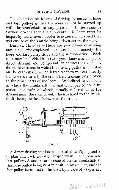
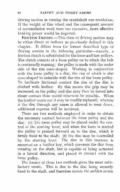
A direct driving motion is illustrated in Figs. 3 and 4,
in plan and back elevation respectively. The loose and
fast pulleys A and A^ are mounted on the crankshaft C,
the loose pulley being kept in position by a collar, and the
fast pulley is secured to the shaft by means of a taper key
SWITI LiDiv-Kl
12 TAPPET AND DOBBY LOOMS
'=^
and set-screws. The belt guide J and the starting lever Kare employed to move the belt on and off the fast pulley.
This is the simplest type of driving motion, and is chiefly
adopted for looms which do not require excessive driving
power, and is specially applicable to lightly-built looms
running at a high speed. With such a drive the torsion
or twisting moment to which the crankshaft is subjected
when the loom is started is only
slight, and the consequent pos-
sibility of breakage is consider-
ably reduced.
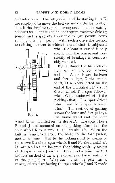
Fig. 5 shows the back eleva-
tion of an indirect driving
motion. A and B are the loose
and fast pulleys, C the crank-
shaft, D a sleeve fitted on the
end of the crankshaft, E a spur
driver wheel, F a spur follower
wheel, G the brake wheel H the
picking - shaft, J a spur driver
wheel, and K a spur follower
wheel. The method of gearing
shows the loose and fast pulleys,
the brake wheel and the spur
wheel E, all mounted on the sleeve D. The spur wheels
F and J are mounted on the picking - shaft H ; the
spur wheel K is secured to the crankshaft. When the
belt is transferred from the loose to the fast pulley,
motion is transmitted to the picking-shaft by means of
the sleeve D and the spur wheels E and F ; the crankshaft
in turn receives motion from the picking-shaft by means
of the spur wheels J and K. The object attained by this
indirect method of driving is to increase the eccentricity
of the going part. With such a driving gear this is
readily effected by having the spur wheels J and K made
Fig. 4.
ECCENTRIC DRIVING WHEELS 13
^a
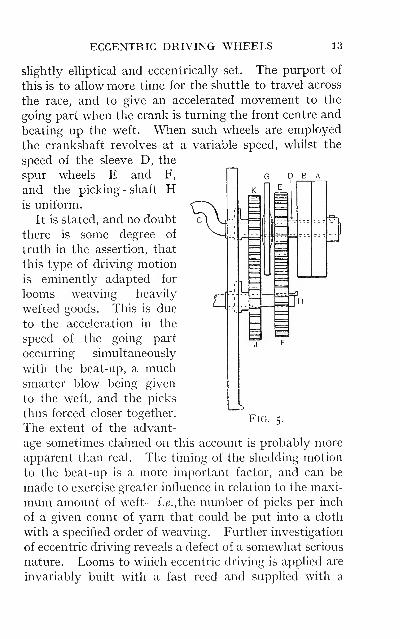
slightly elliptical and eccentrically set. The purport of
this is to allow more time for the shuttle to travel across
the race, and to give an accelerated movement to the
going part when the crank is turning the front centre and
beating up the weft. When such wheels are employed
the crankshaft revolves at a variable speed, whilst the
speed of the sleeve D, the
spur wheels E and F, g d b
and the picking - shaft His uniform.
It is stated, and no doubt
there is some degree of
truth in the assertion, that
this type of driving motion
is eminently adapted for
looms weaving heavily
wefted goods. This is due
to the acceleration in the
speed of the going part
occurring simultaneously
with the beat-up, a muchsmarter blow being given
to the weft, and the picks
thus forced closer together.
The extent of the advant-FiG. 5.
age sometimes claimed on this account is probably moreapparent than real. The timing of the shedding motion
to the beat-up is a more important factor, and can be
made to exercise greater influence in relation to the maxi-
mum amount of weft
—
i.e.,the number of picks per inch
of a given count of yarn that could be put into a cloth
with a specified order of weaving. Further investigation
of eccentric driving reveals a defect of a somewhat serious
nature. Looms to which eccentric driving is applied are
invariably built with a fast reed and supplied with a
14 TAPPET AND DOBBY LOOMS
warp protector stop motion. When the loom through
any cause knocks off, various parts of the loom are sub-
ject to severe shock. Knocking-off is timed to take place
with the crankshaft about the top centre, and as the in-
crease in the momentum of the going part commenceswith the crank in this position, the strain on the various
parts will be increased in a corresponding degree; the
stop motion, lay swords, and driving wheels, are thus
subject to excessive concussion, and the number of break-
ages unduly multiplied.
The following experience in support of this statement
may be of interest : It was deemed desirable to increase
the speed of a certain class of 10/4 looms ten picks per
minute. To facilitate this the adoption of eccentric
wheels was recommended. About half the number of
looms had been supplied with such wheels, when the
necessary alteration in the speed of the line-shaft was
accomplished. A period of unprecedented bad running
of the looms at once set in, a natural outcome of the in-
creased speed, resulting in many breakages, the most
notable being the breaking of the lay swords and the
stripping of the teeth in the driving wheels of those
looms to which the eccentric wheels had been fitted;
these defects being ultimately overcome as the looms
were tuned up to the requirements of the increased speed.
It is not usual to apply eccentric wheels to looms of less
than 10/4 reed space, nor to all looms with a reed space
of from 10 to 12/4, unless they are required to be run at
the highest possible speed. The tendency at the present
time is to supply concentric driving wheels to looms
which have been built formerly with eccentric wheels.
Brake Motions.—In most looms an effective brake is
a necessary adjunct to the driving motion, its function
being to prevent the loom from over-running when
thrown off. There are various types of such motions,
BRAKE MOTIONS 15
each being constructed according to the requirements
of the loom to which it is apphed. Lightly-built looms
running at a high speed are supplied with a brake motion,
which is only brought into operation when the loom is
thrown off by the action of the weft stop motion
—
i.e.,
when the weft supply fails, and in some loose reed looms
by the warp protector. When the loom is stopped
in the usual way by the weaver the brake remains
inoperative.
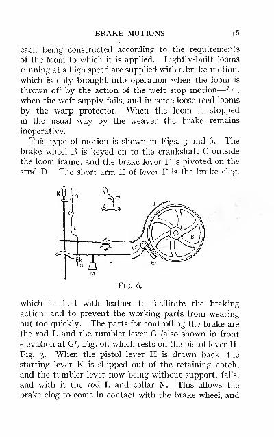
This type of motion is shown in Figs. 3 and 6. The
brake wheel B is keyed on to the crankshaft C outside
the loom frame, and the brake lever F is pivoted on the
stud D. The short arm E of lever F is the brake clog,
w.-^•4
.A V ^
Fig. 6.
which is shod with leather to facilitate the braking
action, and to prevent the working parts from wearing
out too quickly. The parts for controlling the brake are
the rod L and the tumbler lever G (also shown in front
elevation at G\ Fig. 6), which rests on the pistol lever H,
Fig. 3. When the pistol lever H is drawn back, the
starting lever K is shipped out of the retaining notch,
and the tumbler lever now being without support, falls,
and with it the rod L and collar N. This allows the
brake clog to come in contact with the brake wheel, and
16 TAPPET AND DOBBY LOOMS
helps to bring the loom to a state of rest without undueover-running.
Careful setting of the brake is of the utmost import-
ance. When the loom is stopped by the action of the
weft stop motion the brake is applied immediately the
pistol lever is drawn back, and with the belt not quite
clear of the fast pulley. As a result of this the loom is
liable to sudden shock and undue strain. This may be
modified by fixing the collar N on the rod L in such a
position that it will keep the brake clear when the loomis running, and when the loom is thrown off to allow as
long a drop as possible before the brake is applied. Theweight M should be adjusted on the lever in such a
position that it will render the action of the brake as
gentle as possible, stopping the loom with the crank on
the back centre and the shuttle at the shuttling side of
the loom.
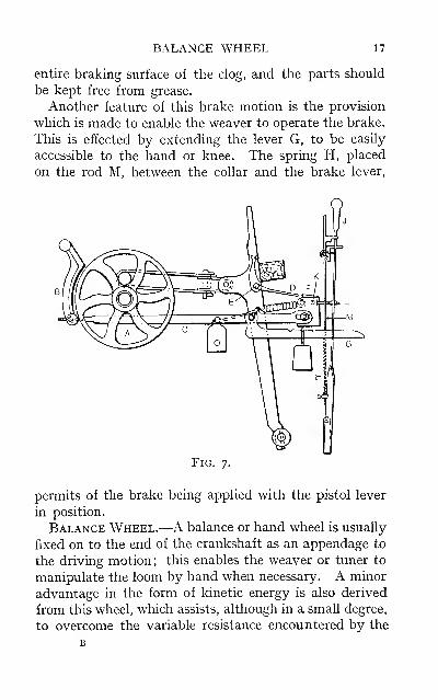
Another type of brake motion is shown in Fig. 7, and
is somewhat similar to that already described. This is
applied to fast reed looms, and differs from the former
type in the following particular—namely, that the brake
is applied to reduce vibration when the loom knocks off.
The brake B is actuated by means of the dagger D, on the
stop rod E, engaging with the frog F, which is attached
to the brake lever C. When the frog is forced forward
by the impact, the brake is drawn in contact with the
brake wheel A. When the brake is actuated from the
frog it should be set so that contact with the brake is
made before the full force of the impact takes place, but
not until the belt is running off the fast pulley.
When knocking-off occurs, the starting lever J is
shipped out of the retaining notch by the projection K,
on the frog F, coming in contact with the T-bolt L, which
is bolted to the starting lever. The brake clog should be
adjusted to the wheel so that it makes contact on the
BALANCE WHEEL 17
entire braking surface of the clog, and the parts should
be kept free from grease.
Another feature of this brake motion is the provision
which is made to enable the weaver to operate the brake.
This is effected by extending the lever G, to be easily
accessible to the hand or knee. The spring H, placed
on the rod M, between the collar and the brake lever,
Fig. 7.
permits of the brake being applied with the pistol lever
in position.
Balance Wheel.—A balance or hand wheel is usually
fixed on to the end of the crankshaft as an appendage to
the driving motion; this enables the weaver or tuner to
manipulate the loom by hand when necessary. A minor
advantage in the form of kinetic energy is also derived
from this wheel, which assists, although in a small degree,
to overcome the variable resistance encountered by the
18 TAPPET AND DOBBY LOOMS
driving motion in turning the crankshaft one revolution.
If the weight of this wheel and the consequent amountof accumulative work were too excessive, more effective
braking power would be required.
Friction Driving.—This class of driving motion maybe either direct or indirect as previously defined in this
chapter. It differs from the former described type of
driving motion in the following particular—namely, a
friction clutch is substituted for the loose and fast pulleys.
The clutch consists of a loose pulley on to which the belt
is continually running; the pulley is made with the under
side of the rim cone-shaped. Working in conjunction
with the loose pulley is a disc, the rim of which is also
cone-shaped to coincide with the rim of the loose pulley.
To facilitate frictional contact the rim of the disc is
clothed with leather. By this means the grip may be
increased, as the pulley and disc may then be forced into
closer contact than would otherwise be possible. Whenthe leather wears out it may be readily replaced; whereas
if the disc through any cause is allowed to wear down,
additional expense will be involved.
There are two methods employed in order to obtain
the necessary contact between the loose pulley and the
disc: (a) The loose pulley may be placed under the con-
trol of the starting lever, and when the loom is started
the pulley is pushed forward on to the disc, which is
firmly fixed to the shaft; (b) the disc may be controlled
by the starting lever. The disc in this instance is
mounted on a feather key, which prevents the disc from
rotating on the shaft, but is capable of being actuated
in a lateral direction, and placed in contact with the
loose pulley.
The former of these two methods gives the most satis-
factory result. This is due to the disc being securely
fixed to the shaft, and therefore resists the sudden strain
FRICTION DRIVING MOTION 19
much more effectively. In the latter method, the disc
being movable, the minimum amount of clearance must
of necessity be allowed between the key and the keywayof the disc. As the key and keyway gradually wear
down, the clearance increases, and an amount of back-
lash takes place when the loom is started. Theresult of this is that the key and keyway in the disc
are liable to be bruised, and as a consequence the disc
will be obstructed in its movement to and from the
loose pulley.
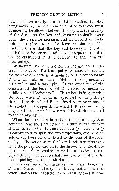
An indirect type of a friction driving motion is illus-
trated in Fig. 8. The loose pulley A, shown in section
for the sake of clearness, is mounted on the countershaft
B, to which is also secured the friction disc C by means of
a taper key and a taper pin. At the other end of the
countershaft the bevel wheel D is fixed by means of
saddle key and lock-nuts E. This wheel is in gear with
the bevel wheel F, which is keyed fast to the picking-
shaft. Directly behind F, and fixed to it by means of
the studs H, is the spur driver wheel J, this in turn being
in gear with the spur follower wheel K, which is secured
to the crankshaft L.
When the loom is set in motion, the loose pulley A is
actuated from the starting lever M through the bracket
N and the rods O and P, and the lever Q. The lever Qis constructed to span the two projections, one on each
side of the loose collar R fitted to the boss of the loose
pulley. The action when the loom is set in motion is to
force the pulley forward on to the disc
—
i.e., in the direc-
tion of A^ When contact is made the motion is con-
veyed through the countershaft and the train of wheels,
to the picking and the crank shafts.
Features and Advantages of this Indirect
Driving Motion.—This type of driving motion possesses
several noticeable features: (i) A ready method is pro-
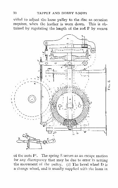
20 TAPPET AND DOBBY LOOMS
vided to adjust the loose pulley to the disc as occasion
requires, when the leather is worn down. This is ob-
tained by regulating the length of the rod P by means
of the nuts P^ The spring vS serves as an escape motionfor any discrepancy that may be due to error in setting
the movement of the pulley. (2) The bevel wheel D is
a change wheel, and is usually supplied with the loom in
FEATURES OF INDIRECT DRIVING 21
three sizes. The substitution of one or other of these
wheels effects a difference in the speed of the loom to the
extent of 20 per cent.
—
i.e., a loom running at the rate of
95 picks per minute with the medium wheel could be
reduced to 90 picks or increased to 100 picks per minute.
The necessary changes can be made in a comparatively
short time, with the line-shaft running, no alteration in
the length of the belt being necessary. This is extremely
useful in some branches of the weaving industry, as whenweaving certain classes of goods the production per loommay be increased by a reduction in the speed. (3) Theconstruction of this type of driving motion is such that
eccentric or concentric wheels may be adopted. (4)
This indirect method of driving necessitates the line-
shaft being run at a much higher speed than if driven
direct. By reason of the increased speed the undesirable
effect on the running of the loom, due to any irregularity
in the speed of the line-shaft, is minimised
—
e.g., assum-ing that a loom is driven direct, and is required to be run
at the rate of 90 picks per minute, the loom pulley is
I4in. diameter and the drum on the line-shaft 25in. dia-
meter. The speed of the line-shaft must equal ^^^ ^4
= 5o| revs, per minute ; or if the drum on the line-shaft
is I5in. diameter, then 9 ^ ^4 ^ g^ j-^^g p^j. minute.
Again, taking the above example, but with indirect
driving, as shown in Fig. 8, full particulars being as
follows: Size of driving drum 25in. diameter, loom pulley
I4in. diameter, number of teeth in bevel D 18, bevel
wheel F on the low shaft 54 teeth, the spur driver andspur follower wheels J and K 36 teeth each. Workingin stages the speed of the countershaft must equal
6 8^^7^ ^^^^- P^^ minute. The speed of the
22 TAPPET AND DOBBY LOOMS
line-shaft to give this speed will be as follows: ~ ^
= 15 14 revs, of line-shaft, showing the velocity ratio of the
indirect drive to the direct drive: [a) With 25in. drum
in each case, as 151-i : 5of ; (&) with 25in. drum and I5in.
drum respectively, as 151 J : 84; the velocity ratio of the
countershaft to the crankshaft being in the proportion
of 270 : 90 revs, per minute
—
i.e., 3:1.
This type of driving motion is adopted on many differ-
ent builds of looms in some modified form
—
e.g., the type
of motion illustrated in Fig. 8 may be supplied with
loose and fast pulleys in place of the friction clutch. In
other looms the countershaft is placed so that the bevel
driver wheel will be in gear with a bevel follower wheel
fixed to the crankshaft of the loom, and not the picking-
shaft as shown in Fig. 8.
Friction driving is usually applied to looms of a heavy
build, to which it is eminently suitable. With friction
driving the full power is transmitted to the loom directly
it is started. The loom attaining full speed immediately,
the liability to knock-off, as is the case with loose and
fast pulley driving, is reduced. A much more effective
drive is also obtained, by reason of the full width of the
belt being utilised to drive the loom. The disadvantage
encountered with this type of driving motion is that
owing to the instantaneous action the parts are subject
to excessive strain, and consequently attended with
greater expense in repairs. The strength of the shaft
and clutch should be such as adequately to resist the
strain apphed. The boss of the loose pulley should have
as much bearing surface on the shaft as possible. This
keeps the pulley in truth with the disc much longer, as
when the loose pulley or the shaft is worn down the action
of the belt on the pulley is to throw it out of truth ; then
when the loom is started the disc is worn down at one
FRICTION DRIVE—BRAKE MOTION 23
part of the circumference before making full contact.
A defect common to friction driving is when the pulley is
not pressed tightly on to the disc, or when oil is allowed
to fall on to the leather, the result being unsteady run-
ning and reduced speed. In all indirect driving motions
a slight loss of power is inevitable with the train of wheels,
but this may be reduced by having the wheels machine-cut.
Brake Motion.—An alternative type of brake motion
to those already described is also shown in Fig. 8. Thebrake in this instance is applied each time the loom is
thrown off. The brake lever T is controlled from the
lever Q which actuates the loose pulley. The brake clog
T^ is secured to the lever T in such a position as to bear
on the side surface of the disc when the loom is thrown
off. When the loom is started the brake clog is pushed
clear of the disc by reason of the reciprocating action of
the lever Q and the brake lever T. With such a brake
motion some considerable difficulty is experienced when-
ever it is desired to manipulate the loom by hand, due to
the action of the brake on the disc. It is not always
advisable to move the loom by means of the belt whenrepairs are being executed, as a certain amount of risk
would be involved on this account. To overcome this a
brake easing motion is supplied. This is shown at the
upper left side of Fig. 8, this part of the diagram being
drawn to half the scale of the other portion. Secured to
the loom frame on a level with the breast beam is a
bracket i carrying the lever 2 pivoted on the stud 3.
The lever is made such a length that when drawn down-
wards it comes in contact with the shipper handle M,
forcing it slightly forward, the result being that the brake
clog is pushed clear of the disc. The amount of move-
ment at this point requires careful and accurate adjust-
ment; otherwise the loose pulley may engage with the
disc and so move the loom at intervals.
24 TAPPET AND DOBBY LOOMS
Speed AND Production.—The ultimate object inpower-
loom weaving is necessarily to obtain the maximum pro-
duction. There are factors which exercise considerable
influence in this direction. The speed of the loom is no
doubt of primary importance. Obviously an essential
feature in loom driving is to have uniform running of the
line-shaft, a factor not always in evidence. This is due
in some instances to the fact that many looms are to be
found installed in rooms altogether unsuitable, which
were not originally intended to accommodate power-
looms, and the motive power is not equal to the require-
ments. In other instances numbers of looms could be
found driven from line-shafts which are turned by the
same engine that is employed to drive other heavymachinery. When the reactionary nature of loomdriving is added to the above, the unsatisfactory results
in the speed and economical running of the looms are
readily explained. These undesirable results are nowhappily a diminishing quantity, special attention being
paid to the above in the modern weaving establishment.
Generally speaking the speed of the loom is governed bythe type of loom and the class of fabric on which it is
engaged. When tender yarns are employed as either
warp or weft, and the loom run at the same speed as for
good elastic yarn, the time occupied by the weaver re-
pairing the increased number of breakages would quickly
counteract the advantage accruing from the high speed.
To this should be added the increased cost of mendingthe pieces, the waste of material, and the decrease in
production.
Another matter of primary importance is the pre-
paration of the yarns for the loom. If in the warpingprocess ends have been allowed to run down and imper-
fect knots tied, or if sizing has not been done successfully
or beaming performed in a slipshod fashion ; and if in the
FACTORS IN PRODUCTION 25
preparation of the weft yarns, the twist, winding, size and
shape of the cops are faulty—any or all of these defects
will diminish the output. The practical tuner will readily
detect any of these or other irregularities, and should
immediately report the same to prevent as far as possible
any repetition. The extent to which the preparatory
processes may or may not be conducive to the maximumoutput, is of such importance as to demand con-
siderably more attention than is usually given to them.
While the above-mentioned points are of sufficient im-
portance to merit the attention of those concerned, the
premier responsibility undoubtedly rests with the tuner.
The duty of the tuner is to keep the looms in good
running order, and produce the maximum output con-
sistent with economy. A factor of importance in this
direction rests in a judicious selection of the work to be
put into the various looms, it being a well-known fact
with the practical tuner that one loom would weave a
difficult piece much better than another loom. In manyweaving sheds the work is portioned out for the looms
by one known as the " putter-up." This position is not
always filled by one who is in possession of practical
experience in so far as the possibilities of the loom are
concerned. The result of this is that the work is por-
tioned out irrespective of its suitability or otherwise
for any particular loom. Therefore the tuner should be
allowed to exercise his practical experience in the selec-
tion of the work to be put into the looms under his care.
Speed Calculations.—The following formula maybe employed to ascertain the speed of shafts, size of
drum and change wheels required:
—
Formula : DR=dr
;
where D = diameter of the first driver or product of all
drivers; R = number of revolutions per minute of the
first driver; rf = diameter of the first follower or product
26 TAPPET AND DOBBY LOOMS
of all followers ; ;' = number of revolutions per minute of
the last follower.
Taking the calculation as given above, it is required to
find the speed of the line-shaft to run the loom at the rate
of 90 picks per minute.
By formula : D K = dr ;
i.e.,
D X R = d X y
25 X 18 X 36 X ;t = 14 X 54 X 36 X 90.
14x1:4X36x90 , J ri- u r..'. x= -^—^ ^^—7^= I'll? revs., speed of hne-shaft.
25 X 18 X 36 ^ ^ ' ^
Or if it is required to find size of drum on the line-shaft
—
T>R = dr.
a; X 18 X 36 X 151J = 14 X 54 X 36 X 90.
14 X 1^4 X 36 X no . . ^ J.*. X = ^^ ^^
^
^ = 25m. size of drum.18X36X 1511-
Or if it is required to find the number of teeth in the
bevel change wheel
—
DR^rf;'.
25 X ^ X 36 X 1511= 14 X 54 X 36 X 90.
^.^^_14x54^^36^^9^^,
8 teeth.25X36X 151!
And similarly when it is required to find any one of the
remaining factors.
N.B.—The factors 36 on each side of the equation maybe omitted.
Transmitting Motion Throughout the Loom.—It
will be evident from what has been already stated con-
cerning the driving motion that its function is to impart
motion to the primary shafts
—
i.e., the crank and low
shafts. From- these, motion is then conveyed either
directly or indirectly to the remaining parts of the loom.
PRINCIPLES GF MOTION * 27
There are numerous principles exemplified and employed
in order to perform the several motions required in power-
loom weaving
—
e.g., (i) Spur and bevel wheel gearing;
(2) worm and worm-wheel gearing; (3) ratchet wheel
and pawl. These principles illustrate both continuous
and intermittent motions, of which the method of driv-
ing the tappets in tappet looms, and the dobby in some
dobby looms, are examples of the continuous motion;
whilst the picking and box motions on all looms are
illustrative of the intermittent motion. In addition to
the above principles there is another of equal import-
ance—viz., the principle of levers, examples of which are
to be found in the mechanism of all box motions. In
view of the above remarks it will appear as though the
tuner must possess a general knowledge of mechanics.
This is the opinion of the writer, who, from observation
and actual experience, does not hesitate to say that the
more efficient the tuner is in the study of mechanics the
more successful will he be as a tuner. That there are
successful tuners who have never had any special train-
ing in theoretical or applied mechanics is a fact not to be
gainsaid, but such have only arrived at their present
state of efficiency after many years of practical acquaint-
ance with the loom ; and such experience could probably
have been acquired by much less laborious work had
they possessed some knowledge of the subject referred
to. It is not the intention nor wish to incur the resent-
ment of any tuner, but merely to point out that someacquaintance and knowledge of applied mechanics and
kindred subjects is well worth acquiring. That such
knowledge would not only prove helpful but would also
yield additional interest in the work is readily admitted.
One fact in support of this contention is that the man of
" rule-of-thumb " methods is being superseded by the
more advanced and technically-trained workman.
CHAPTER II
MOTIONS OF THE LOOM
The several motions in power-loom weaving are usually
divided (by the theorist) into the following:—Primary
motions: Shedding, picking and beating-up. Second-
ary motions: Letting-off the warp and setting-up.
Auxilary motions: Box motion, weft stop motion, etc.
Proceeding to discuss the several motions, it is only a
minor matter in which order they are dealt with.
Beating-up Motion.—This is no doubt the one motion
of the three primaries that could be discussed at con-
siderable length from a theoretical standpoint. How-
ever, it is from the practical point of view that it must
be approached. The object of this motion is to control
the going part or lay of the loom. The going part serves
the dual purpose of beating-up the weft when in its front
position, and provides a ready medium when in the back
position, on which the shuttle may travel from box to
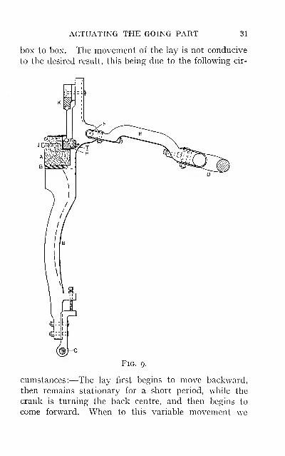
box. Fig. 9 illustrates, in side elevation, the most gener-
ally adopted method of actuating the going part of the
loom. The lay A consists of a beam of wood which, in
plain one-shuttle looms, is extended to such a length as
to allow the shuttle-boxes being built upon it. Whenthe loom is supplied with a number of boxes at
one or both ends, then the lay only extends to
within half-an-inch of the shuttle-boxes. The lay is
supported on the lay swords B, these being usually
constructed with a projecting arm, to which the lay
28
CONSTRUCTION OF GOING PARTS 29
is firmly bolted to ensure absolute rigidity. The lay
sword is centred on the rocking shaft C, which in some
looms is a short shaft, but in others it extends from one
lay sword to the other. Motion is conveyed to the going
part from the crank D by means of the connecting armE, this being secured at one end to the crank and at the
other end to the connector pin F.
Construction of the Going Part.—An observation
of the cross-section of several going parts shows that the
method of construction has been to obtain such condi-
tions of strength as will effectively resist the excessive
strain to which they are subject. Some are made in one
solid piece, with a groove cut in the upper portion to
accommodate the bottom rib of the slay. Directly be-
hind the groove an iron plate is secured, fin. thick and
2in. deep, which is carried the full width of the reed space
for the purpose of giving additional strength. In some
looms an angle plate is used, this being secured to the
back and bottom of the lay. Another method adopted
on some box looms is to construct the lay of two battens,
running in the direction of the reed; the back portion is
grooved to admit the lower rib of the slay, and only ex-
tends to the shuttle-box. The front portion is carried
forward, and assists in supporting the framework of the
boxes, of which it may be said to form a part. This type
possesses an advantage over the former, because it pre-
vents to some extent the possibility of the wood warping
if it is not properly seasoned.
Another type is shown in Fig. 9. Here the portion
shaded at G represents the metal of the projecting armon the lay sword, which extends some i6in. along the lay.
To accommodate the lower rib of the reed a portion of the
batten is cut away, the groove being formed by the
separate lath H, to which is screwed the iron plate T.
To grip the reed the lath H is drawn forward and held
30 TAPPET AND DOBBY LOOMS
firmly in position by means of the bolts J, which pass
through the lay and are tapped into the plate T. The
reed in each case is kept in position at the top by the slay-
cap K ; this may be made of iron or of wood, strengthened
by the addition of an iron plate.
To the top of the lay on which the shuttle travels it is
usual to provide a special race. This in some looms is
made of wood ; in others it takes the form of a steel plate.
Of these two types the following advantage is claimed
for the former—namely, that the warp threads are not so
readily cut by the shuttle passing over them. When the
boxes are out of truth, or the picking faulty, the shuttle
may be thrown down on to the race, as it leaves the box,
with such force that the threads are chopped. This is
more prevalent when weaving fine warps, and to obviate
this the following method is sometimes practised. Therace is covered with cloth, piece ends being used for this
purpose. The cloth is first tacked to the front of the lay,
then folded back over the race and laid over the groove,
into which it is pressed and held tightly in position bythe reed. A little extra pick is required under these
circumstances, due to additional frictional resistance,
but warps of fine counts, and those with a small numberof ends per inch, have been made to weave much better
by the adoption of this method, the cloth forming a sort
of cushion for the warp. The objectionable feature of
the wood race is that small grooves are cut into it if the
shed is boarding too heavily, and especially when weav-
ing coarse warps, the result being that any knots coming
up in the warp catch in the grooves and are broken.
Movement of the Going Part and Flying Shuttle.
—It is of the utmost importance that the going part
works in absolute truth. The nature of the movementimparted to the lay is such that the shuttle should have
every point in its favour during its passage across from
ACTUATING THE GOING PART 31
box to box. The movement of the lay is not conducive
to the desired result, this being due to the following cir-
FiG. 9.
cumstances:—The lay first begins to move backward,
then remains stationary for a short period, while the
crank is turning the back centre, and then begins to
come forward. When to this variable movement we
32 TAPPET AND DOBBY LOOMS
add other possible discrepancies, the importance of a
true race is apparent. One of the many causes of " fly-
ing shuttles " is the lay being out of truth, and this de-
fect may be traced to some of the following:
—
(a) Theangle formed by the race-board and the slay not being
exactly the same as the bevel of the shuttle;
(b) the slay
and back of the shuttle-box not being in alignment; (c)
the race and bottom of the shuttle-box being out of
truth, and especially in box looms. Whenever the
shuttle begins to work unsatisfactorily the race should
be tested. This is usually done by means of a straight-
edge, which is first placed at the entrance of the
shuttle-box, testing the slay with the back of the box,
then the race with the bottom of the box ; if a box loom,
each box should be tested. The straight-edge is next run
across the reed, as it sometimes happens that this is
found to be defective. This may be due to a bulge in the
reed, or to some hard substance accidentally getting into
the groove before putting in the reed when starting the
loom. Healding hook, slay knife, and brooches have
sometimes been the source of trouble. Should this
simple test fail, then a more exhaustive one should be
made, assuming, of course, that the race is at fault.
This may be done by testing the angle formed by the race
and slay across the lay, then testing by means of a plumb-
line stretched tightly across the lay from the back of the
shuttle-boxes, and comparing extreme and corresponding
measurements.
Another defect productive of serious results is due to
the going part not working square throughout its stroke.
This is brought about by reason of the connecting arms
being packed, to avoid too much chase and consequent
erratic movement of the going part, when beating-up
and picking take place. The packing of the arms being
necessary when the bushes have become very much worn,
DEFECTIVE WORKING OF THE GOING PART 33
this defect is often brought about by unequal packing.
A similar defect will be set up if the positions of the rock-
ing shafts are not identical with each other. In each
instance the reed would not meet the cloth squarely, andif in a loom provided with a warp protector, the protector
blade would not strike the frogs at the same time, proving
a fruitful source of unnecessary breakages. In looms
where an additional connecting arm is employed to con-
nect the shuttle-box end to the stud in the balance
wheel, the arm should be set with the greatest accuracy,
otherwise the box will work on the twist.
The Stroke of the Going Part.—The stroke of the
going part is practically determined by the size
—
i.e.,
the cross-section—of the shuttle to be used. Anyattempt to form a large shed with too short a distance
between the fell of the cloth and the healds, can only
result in the warp threads being subject to excessive
tension. The distance travelled by the going part
during such time as the crank is turning from the front
to the back centre is determined by the sweep of the
crank, the position of the connecting pin in the lay
sword, and also in a minor degree by the position of the
crankshaft in relation to the oblique plane passing
through the centre of the connecting pin, when in the
full forward and backward positions respectively. Whenthe centre of the crankshaft is placed in the same plane
as the connecting pin referred to, the distance travelled
by the connecting pin will be equal to the sweep of the
crank. It is usual to fix the connecting pin in the lay
sword immediately behind the point of resistance to the
going part when beating-up takes place (such position
being selected in order to prevent breakages of the lay
swords). The stroke, therefore, of the going part will
coincide with the stroke of the pin when the above con-
ditions obtain. It is occasionally required to make a
c
34 TAPPET AND DOBBY LOOMS
slight alteration in the position of the bottom-shed line
of the warp, and, consequently, in the relative position
of the going part. The height of the going part is readily
effected by an alteration in the length of the lay swords.
When this is necessary the stroke of the going part will
also be affected, due to the centre of the crankshaft not
now being in the same plane with the connecting pin as
referred to above.
There are two factors which necessitate the stroke of
the going part being made as short as possible. First:
When considered in relation to the speed at which it is
desired to run the loom, it will be obvious that the larger
the crank employed the greater will be the distance
travelled by the going part, and consequently moretime must be allowed. This factor evidently fixes the
limit either to the stroke or to the speed at which
the loom could be run. Second: It is not desirable
to have too large a stroke, otherwise the chafing to
which the warp is subject by the action of the reed
will be increased.
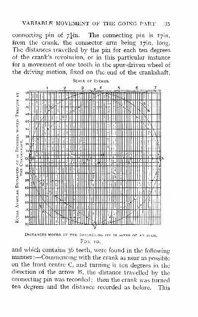
The Nature of the Motion Imparted to the GoingPart.— It must not be assumed that the following
remarks profess to deal conclusively with this part
of the subject. The nature of the motion obtained
by means of a crank is practically the style of motion
to be desired. Fig. lo is introduced with the object
of illustrating in a simple manner the variation of
the movement, or the eccentricity transmitted from
the crank to the going part. The particulars have
been taken from a well-known type of loom, the
measurements being recorded to the nearest twentieth
of an inch, and are therefore only approximately
correct. The circle A represents one revolution of
the crankshaft turning in the direction of the arrow B.
The radius of the crank is 3|in., yielding a stroke to the
VARIABLE MOVEMENT OF THE GOING PART 35
connecting pin of 7iin. The connecting pin is i7in.
from the crank, the connector arm being i7in. long.
The distances travelled by the pin for each ten degrees
of the crank's revolution, or in this particular instance
for a movement of one tooth in the spur-driven wheel of
the driving motion, fixed on the end of the crankshaft,
36 TAPPET AND DOBBY LOOMS
order was repeated until the crank was again on the front
centre.
The broken hne G is obtained by plotting through the
points already recorded; these points representing the
distance travelled by the connecting pin for each io° of
rotation of the crankshaft, or the distances travelled in
equal times. For the sake of clearness each of these
points is shown projected on to the centre-scale line.
From this scale the diversity of the movements imparted
to the connecting pin, and simultaneously to the going
part, at various stages of the crankshaft's revolution,
may now be noted.
Reading from the front centre C to the first point, the
distance moved by the connecting pin is shown to be
J^th of an inch ; for the next io° 4\ths of an inch. The
next reading shows a much greater distance—namely,
^\ths of an inch. From this point a gradual increase is
noticed for each io° until the crank has reached the top
centre D. Tracing the line G forward from the top
centre it will be noticed that the distance from point to
point gradually diminishes until the back centre E is
reached. From the back centre to the bottom centre Fthe distances increase in similar (but inverse) ratio as
they decrease from the top to the back centre. Fromthe bottom centre to the front centre the distances de-
crease in similar inverse ratio as they increase from the
front to the top centre.
Motion of the Going Part During the Time the
Crank is Turning About the Four Centres.—The
following comparisons may now be made, the difference
in the respective distances only being calculated to the
twentieth of an inch, (a) The total distances travelled
by the connecting pin during the time the crank is turn-
ing from one centre to the next are indicated by the lines
H, J, K, and L respectively, and are shown to be accord-
ADVANTAGES OF ECCENTRIC MOTION 37
ing to the order of rotation 82, 63, 67, and 78 twentieths
of an inch, (b) Comparing the distances travelled by the
crank for each 90°, or from one centre to the next, with
the above distances of the connecting pin, it will be
observed that the pin moves a greater distance by oV^^^of an inch more than the radius of the crank during the
first 90°. While the crank is turning from the top to the
back centre, the distance travelled by the connecting pin
when compared with that of the crank is /^ths of an inch
less. During the time the crank is turning from the
back to the bottom centre, the distance of the connecting
pin, compared with that of the crank, is shown to be
,/q ths of an inch less ; and while the crank is passing from
the bottom to the front centre, the pin moves ^V^^^ ^^ ^^
inch more than the crank, (c) A further comparison
may now be made with respect to the difference of the
dwell which takes place in the going part, during the
time the crank is turning an equal number of degrees
about the front and back centres. Taking an equal
number of degrees, say 40, on each side of these centres,
the distances travelled by the going part at these periods
are as follows:—The distance travelled for the 40° as
the going part approaches the front centre is ^fths of an
inch; the distance for the 40° as the going part recedes
from the front centre is #iths of an inch. This gives
a total distance of il^ths, practically 2in. The corre-
sponding distances for the same number of degrees about
the back centre are shown to be IJths and ^^ths, giving
a total distance of f^ths of an inch, or i.4in. This
proves clearly that the going part travels more quickly
when the crank is turning about the front centre, than
when turning the back centre, as it travels a greater dis-
tance in the same time; but the lengthened pause or
dwell occurs exactly at the time when most needed
—
i.e., as the shuttle travels across the race, (rf) The
38 TAPPET AND DOBBY LOOMS
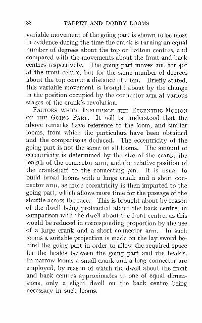
variable movement of the going part is shown to be mostin evidence during the time the crank is turning an equal
number of degrees about the top or bottom centres, andcompared with the movements about the front and backcentres respectively. The going part moves 2in. for 40°
at the front centre, but for the same number of degrees
about the top centre a distance of 4.6in. Briefly stated,
this variable movement is brought about by the changein the position occupied by the connector arm at various
stages of the crank's revolution.
Factors which Influence the Eccentric MotionOF THE Going Part.—It will be understood that the
above remarks have reference to the loom, and similar
looms, from which the particulars have been obtained
and the comparisons deduced. The eccentricity of the
going part is not the same on all looms. The amount of
eccentricity is determined by the size of the crank, the
length of the connector arm, and the relative position of
the crankshaft to the connecting pin. It is usual to
build broad looms with a large crank and a short con-
nector arm, as more eccentricity is then imparted to the
going part, which allows more time for the passage of the
shuttle across the race. This is brought about by reason
of the dwell being protracted about the back centre, in
comparison with the dwell about the front centre, as this
would be reduced in corresponding proportion by the use
of a large crank and a short connector arm. In such
looms a suitable projection is made on the lay sword be-
hind the going part in order to allow the required space
for the healds between the going part and the healds.
In narrow looms a small crank and a long connector are
employed, by reason of which the dwell about the front
and back centres approximates to one of equal dimen-
sions, only a slight dwell on the back centre being
necessary in such looms.
BEATING-UP 39
In broad looms, and also in looms of medium width,
where it is not desirable to employ a large crank on
account of the speed at which the loom is required to be
run, eccentric wheels are introduced into the driving
motion. These wheels are set in such relation to each
other that the speed of the crank and the going part is
reduced about the back centre for the passage of the
shuttle, and accelerated about the front centre.
The Position of the Reed when Beating-up.—On some looms the position of the going part, and con-
sequently the position of the reed when beating-up the
weft, does not allow of any alteration. This is brought
about by reason of the rocking shaft C, Fig. 9, being
centred in a fixed position. In some looms the journal
is made in the loom frame; therefore, any adjustment
in the position of the rocking shaft is impossible. Onother looms the rocking shaft is supported in a movable
bracket, so that a slight alteration in the position of the
going part and the reed may be effected. If the methods
adopted on many modern looms might be taken as evi-
dence, the tendency is to make the position of the rock-
ing shaft a fixed one. This decision on the part of the
loom-makers is substantiated by practical experience,
and especially for looms weaving a variety of cloths.
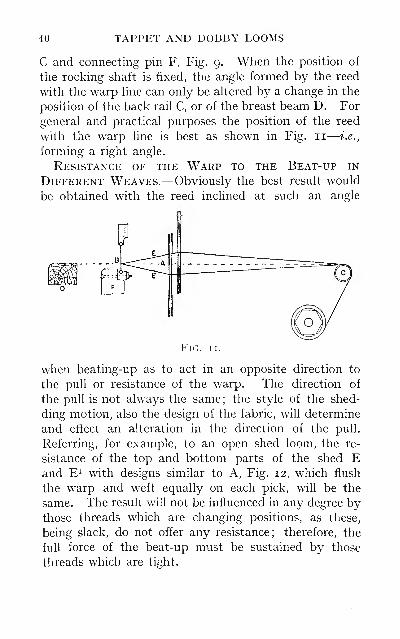
The reed at the beat-up should never be any further
forward than a vertical plane passing through the centre
of the rocking shaft. If the reed be allowed to pass this
point, the probable result wiU be that instead of the reed
meeting the cloth at right angles to the warp line A, Fig.
II, and thereby giving a smart blow to the weft, the
cloth will slide down towards the bottom of the reed B.
In addition to this, when the reed passes the vertical
plane referred to, the lay F begins to dip, and as a result
the maximum amount of vibration in the going part
takes place, to the extent of the chase in the rocking shalt
40 TAPPET AND DOBBY LOOMS
C and connecting pin F, Fig. 9. When the position of
the rocking shaft is fixed, the angle formed by the reed
with the warp hne can only be altered by a change in the
position of the back rail C, or of the breast beam D. For
general and practical purposes the position of the reed
with the warp line is best as shown in Fig. 11
—
i.e.,
forming a right angle.
Resistance of the Warp to the Beat-up in
Different Weaves.—Obviously the best result would
be obtained with the reed inclined at such an angle
Fig
when beating-up as to act in an opposite direction to
the pull or resistance of the warp. The direction of
the pull is not always the same; the style of the shed-
ding motion, also the design of the fabric, will determine
and effect an alteration in the direction of the pull.
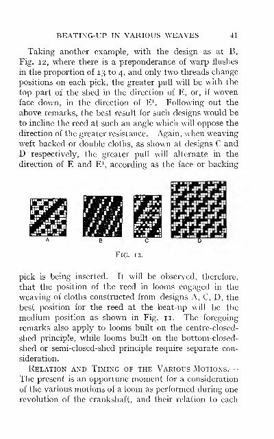
Referring, for example, to an open shed loom, the re-
sistance of the top and bottom parts of the shed Eand E^ with designs similar to A, Fig. 12, which flush
the warp and weft equally on each pick, will be the
same. The result will not be influenced in any degree bythose threads which are changing positions, as these,
being slack, do not offer any resistance; therefore, the
full force of the beat-up must be sustained by those
threads which are tight.
BEATIXG-UP IN VARIOUS WEAVES 41
Taking another example, with the design as at B,
Fig. 12, where there is a preponderance of warp flushes
in the proportion of 13 to 4, and only two threads change
positions on each pick, the greater pull will be with the
top part of the shed in the direction of E, or, if wovenface down, in the direction of E^. Following out the
above remarks, the best result for such designs w^ould be
to incline the reed at such an angle which will oppose the
direction of the greater resistance. Again, when weaving
weft-backed or double cloths, as shown at designs C and
D respectively, the greater pull will alternate in the
direction of E and E^, according as the face or backing
Fig. 12.
pick is being inserted. It wih be observed, therefore,
that the position of the reed in looms engaged in the
weaving of cloths constructed from designs A, C, D, the
best position for the reed at the beat-up will be the
medium position as shown in Fig. 11. The foregoing
remarks also apply to looms built on the centre-closed-
shed principle, while looms built on the bottom-closed-
shed or semi-closed-shed principle require separate con-
sideration.
Relation and Timing of the Various Motions.—The present is an opportune moment for a consideration
of the various motions of a loom as performed during one
revolution of the crankshaft, and their relation to each
42 TAPPET AND DOBBY LOOMS
other. It will be advantageous if the motions are con-
sidered with reference to Fig. lo. As this diagram
illustrates the variable movement of the going part, it
will be seen more clearly how important is the timing of
the several motions to each other, and, in addition,
the timing of the motions which are more directly
affected by the variable speed of the going part may be
observed.
The circle of timing is shown in Fig. 13, the particulars
being taken from the same loom as were those for Fig. 10,
but they are more or less typical of the cycle of opera-
tions performed on most tappet and dobby looms. Theonly point of difference is the direction in which the
crankshaft rotates, which, in this instance, is as shown
by the arrow B ; but it may be mentioned that this order
of rotation is not generally adopted.
Picking Motion.—The position for the timing of the
picking motion may be first located. This motion
admits of little alteration with respect to the time at
which it may operate. The timing shown is the mediumposition, and may be altered to take place from 10° to
15° sooner or later, according to requirements. The
timing is indicated by the radial lines A, D, Dp D2, and
D3. The line A D shows the position for the commence-
ment of the pick
—
i.e., the picking bowl is just in contact
with the shoe. D^ denotes the position at which the
picking connections are drawn tight, with the shuttle
beginning to move out of the box. Do shows the posi-
tion for the delivery of the actual blow to the shuttle.
The distance from D^ to D3 indicates the time allowed
for the passage of the shuttle across the race, though the
position of D.^ varies considerably, being determined by
the reed space of the loom, and the weight of and resistance
to the shuttle. Taking this illustration as being typical
of a 10/4 loom, then the number of degrees for the pas-
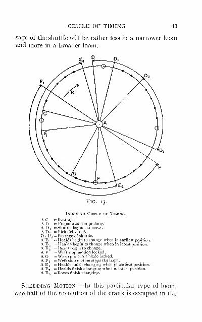
CIRCLE OF TIMING 43
sage of the shuttle will be rather less in a narrower loomand more in a broader loom.
Fig. 13.
Index to Circle of Timing.
AC - Beat-up.
AD = Preparation for picking.
A Di =vShuttle begins to move.AD. = Pick delivered.
D2 D3 = Passage of shuttle.
A'E =Healds begin to change when in earliest position.
A E„ = Healds begin to change when in latest position.
A E2 = Koxes begin to change.
A F = Weft stop motion locked.
A G_ =Warp protector blade locked.
A Ff = Weft stop motion stops the loom.
A El — Healds finish changing when in earliest position.
A E3 = Healds finish changing when in latest position.
A E3 = Boxes finish changing.
Shedding Motion.—In this particular type of loom,
one-half of the revolution of the crank is occupied in the
44 TAPPET AND DOBBY LOOMS
formation of the shed, and the remaining half
—
i.e., i8o°
—for the dwell of the healds. As the picking motion
requires only one-third of a revolution, or 120°, it is
evident that considerable scope is afforded for the timing
of the shedding motion—to the extent of 60°. Theearliest position at which shedding can take place is
immediately after the shuttle has passed through the
shed
—
i.e., at point Dg. When shedding commences at
point E, the shed will be completely formed 180° later,
as shown at E^, which is 20° past the point of the beat-up.
The latest position at which the shed can be formed is
determined by the position at which picking commences,
as the shed must be fully formed to admit the shuttle at
this point. Marking 180° backward from the point E^,
the latest position at which the formation of the shed
can take place is shown at E^, so that the shed would be
more than half formed at the time of beating-up. In
some dobby looms more time is allowed for the formation
of the shed, with a corresponding less time for the dwell
of the healds. In two-tappet looms the principal allow-
ances are J for the change and J for the dwell, or § for the
change and J for the dwell.
Box Motion.—The boxes must have arrived at a
state of rest before the picking can take place, and
they must remain in that position until the shuttle is
well into the opposite box. On many looms fitted
with a rising or drop box motion, the time allowed
for changing the boxes is equal to J a revolution of
the crankshaft, which then allows J a revolution for
the boxes to remain stationary, yielding 60° clearance
in excess of the time taken up by the picking. In
looms fitted with a circular box motion the time for
changing the boxes is rather less. It is usual to time
the box motion so that the boxes are not less than half-
way changed in position at the time of beating-up.

TIMING OF VARIOUS MOTIONS 45
When in this position the shuttle-checking motion has
ahowed the pickers to fah back, and, being quite clear of
the box shelves and shuttle tips, they cannot then
obstruct the movement of the boxes. The position of
timing is shown in Fig. 13, commencing at point E., and
finishing at E3
—
i.e., the boxes are set level with the
shedding motion when the latter is in its latest position.
The warp protector stop motion and the weft stop
motion are instantaneous and not protracted in their
action, as are the motions already dealt with. Thepositions at which these motions take place are shown at
points G, F, and F^ respectively. This remark is also
applicable to the beat-up, which, in this instance, occurs
at point C, which is 10° past the front centre.
Letting-off and Setting-up Motions.—When these
motions are of a negative character, they are performed
simultaneously with the beating-up of the weft. If
they are of a positive nature, the timing will vary accord-
ing to the style of the mechanism employed.
Of the several motions discussed, it will be observed
that the passage of the shuttle, the box motion, and the
warp protector motion, is more or less affected by the
eccentricity of the going part. Referring to the amountof work done at any period of the crank's revolution,
it will be noticed that the most strain is put uponthe loom about the front centre, as then the shed-
ding, box and beating-up motions are being simultane-
ously manipulated, whilst the loom practically runs
light during the time the crank is turning the back
centre.
CHAPTER III
SHEDDING MECHANISM
The simplest type of shedding motion is that in which
the shed is formed by means of tappets. This principle
lends itself in various forms to extensive application.
The principle of this type of shedding consists in using a
tappet which impinges upon an anti-friction roller sup-
ported in a lever, known as the treadle, the heald shaft
])eing connected, directly or indirectly, to the treadle
from which it is operated. The contour or throw of the
tappet may be of any form within certain limitations.
Tappet motions are constructed to give one of twosystems of shedding: (a) Negative shedding, in which
the heald shaft is operated in one direction only by the
tappet
—
i.e., the heald shaft may be lifted or drawn
down, some additional mechanism being required to re-
verse the action of the tappet, (b) Positive shedding, in
which the heald shaft is actuated in both directions in a
positive manner. The tappets may be applied to the loom
in one of two ways—either inside the loom under the
healds, or outside the loom frame. Negative tappets
are employed in either position, but positive tappets are
placed outside the loom.
The following are typical of the variety of forms and
methods of applying tappets to the power-loom for shed
formation. The most elementary form of tappet shed-
ding motion is one which is constructed to control two
heald shafts; these latter receive a reciprocating motion
and produce the plain weave. This is a type of inside
46
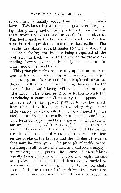
TAPPET SHEDDING MOTIONS 47
tappet, and is usually adopted on the ordinary calico
loom. This latter is constructed to give alternate pick-
ing, the picking motion being actuated from the low
shaft, which revolves at half the speed of the crankshaft.
This factor enables the tappets to be fixed upon the low
shaft in such a position as to actuate the treadles. The
treadles are placed at right angles to the low shaft and
the heald shafts; the treadles being supported at the
heel from the back rail, with the end of the treadle ex-
tending forward, so as to be easily connected to the
under side of the heald shaft.
This principle is also occasionally applied in combina-
tion with other forms of tappet shedding, the object
being to operate the skeleton shafts employed to control
the selvage threads, which work plain, the w^ave for the
body of the material being twill or some other order of
interlacing. The former principle is further extended by
introducing a countershaft to carry the tappets. The
tappet shaft is then placed parallel to the low shaft,
from which it is driven by spur-wheel gearing. Somelittle variety of weave effect may be obtained by th s
method, as there are usually four treadles employed.
This form of tappet shedding is generally employed on
narrow looms engaged in weaving light goods from fine
yarns. By reason of the small space available for the
treadles and tappets, this method imposes limitations
on the stroke of the tappets and the number of treadles
that may be employed. The principle of inside tappet
shedding is still further extended in broad looms engaged
in weaving heavy goods, the weave of such fabrics
usually being complete on not more than eight threads
and picks. The tappets in this instance are carried on
a countershaft placed at right angles to the low shaft,
from which the countershaft is driven by bevel-wheel
gearing. There are two types of tappets employed in
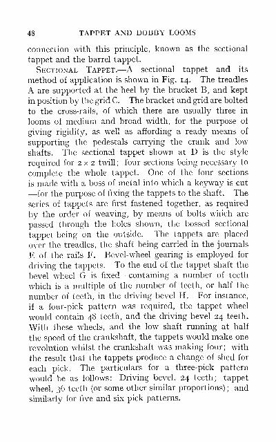
48 TAPPET AND DOBBY LOOMS
connection with this principle, known as the sectional
tappet and the barrel tappet.
Sectional Tappet.—A sectional tappet and its
method of application is shown in Fig. 14. The treadles
A are supported at the heel by the bracket B, and kept
in position by the grid C. The bracket and grid are bolted
to the cross-rails, of which there are usually three in
looms of medium and broad width, for the purpose of
giving rigidity, as well as affording a ready means of
supporting the pedestals carrying the crank and low
shafts. The sectional tappet shown at D is the style
required for 2 x 2 twill; four sections being necessary to
complete the whole tappet. One of the four sections
is made with a boss of metal into which a keyway is cut
—for the purpose of fixing the tappets to the shaft. The
series of tappets are first fastened together, as required
by the order of weaving, by means of bolts which are
passed through the holes shown, the bossed sectional
tappet being on the outside. The tappets are placed
over the treadles, the shaft being carried in the journals
E of the rails F. Bevel-wheel gearing is employed for
driving the tappets. To the end of the tappet shaft the
bevel wheel G is fixed—containing a number of teeth
which is a multiple of the number of teeth, or half the
number of teeth, in the driving bevel H. For instance,
if a four-pick pattern was required, the tappet wheel
would contain 48 teeth, and the driving bevel 24 teeth.
With these wheels, and the low shaft running at half
the speed of the crankshaft, the tappets would make one
revolution whilst the crankshaft was making four; with
the result that the tappets produce a change of shed for
each pick. The particulars for a three-pick pattern
would be as follows: Driving bevel, 24 teeth; tappet
wheel, 36 teeth (or some other similar proportions) ; and
similarly for five and six pick patterns.
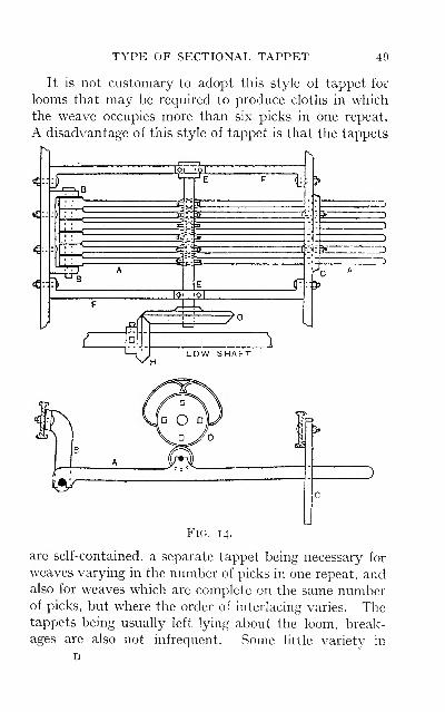
TYPE OF SECTIONAL TAPPET 49
It is not customary to adopt this style of tappet for
looms that may be required to produce cloths in which
the weave occupies more than six picks in one repeat.
A disadvantage of this style of tappet is that the tappets
4-
'I.
^--:^
^. 1
lo 01
A^u ^G
r\
i>Z
M/hLOW SHAFT
Fig. 14.
are self-contained, a separate tappet being necessary for
weaves varying in the number of picks in one repeat, andalso for weaves which are complete on the same numberof picks, but where the order of interlacing varies. Thetappets being usually left lying about the loom, break-
ages are also not infrequent. Some little variety in
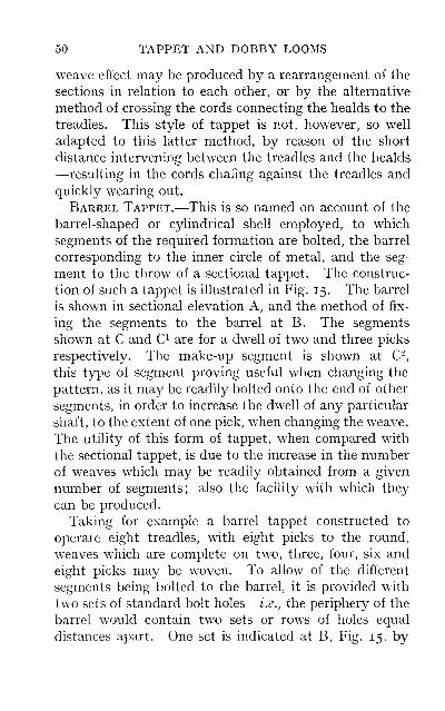
50 TAPPET AND DOBBY LOOMS
weave effect may be produced by a rearrangement of the
sections in relation to each other, or by the alternative
method of crossing the cords connecting the healds to the
treadles. This style of tappet is not, however, so well
adapted to this latter method, by reason of the short
distance intervening between the treadles and the healds
—resulting in the cords chafing against the treadles and
quickly wearing out.
Barrel Tappet.—This is so named on account of the
barrel-shaped or cylindrical shell employed, to which
segments of the required formation are bolted, the barrel
corresponding to the inner circle of metal, and the seg-
ment to the throw of a sectional tappet. The construc-
tion of such a tappet is illustrated in Fig. 15. The barrel
is shown in sectional elevation A, and the method of fix-
ing the segments to the barrel at B. The segments
shown at C and C^ are for a dwell of two and three picks
respectively. The make-up segment is shown at C^,
this type of segment proving useful when changing the
pattern, as it may be readily bolted onto the end of other
segments, in order to increase the dwell of any particular
shaft, to the extent of one pick, when changing the weave.
The utility of this form of tappet, when compared with
the sectional tappet, is due to the increase in the numberof weaves which may be readily obtained from a given
number of segments; also the facility with which they
can be produced.
Taking for example a barrel tappet constructed to
operate eight treadles, with eight picks to the round,
weaves which are complete on two, three, four, six and
eight picks may be woven. To allow of the different
segments being bolted to the barrel, it is provided with
two sets of standard bolt holes
—
i.e., the periphery of the
barrel would contain two sets or rows of holes equal
distances apart. One set is indicated at B, Fig. 15, by
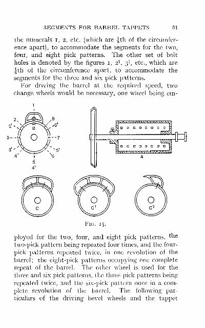
SEGMENTS FOR BARREL TAPPETS 51
the numerals i, 2, etc. (which are Jth of the circumfer-
ence apart), to accommodate the segments for the two,
four, and eight pick patterns. The other set of bolt
holes is denoted by the figures i, 2^ 3^ etc., which are
Jth of the circumference apart, to accommodate the
segments for the three and six pick patterns.
For driving the barrel at the required speed, twochange wheels would be necessary, one wheel being em-
(^
>..'kMH.MLl.VkMRM k'.1«v«.I^V^I
a a Q D a
1 D a o a o
SJL\MSM\MSS I SHLSnS'1,SJ
Fig. 15.
ployed for the two, four, and eight pick patterns, the
two-pick pattern being repeated four times, and the four-
pick patterns repeated twice, in one revolution of the
barrel; the eight-pick patterns occupying one complete
repeat of the barrel. The other wheel is used for the
three and six pick patterns, the three- pick patterns being
repeated twice, and the six-pick pattern once in a com-
plete revolution of the barrel. The following par-
ticulars of the driving bevel wheels and the tappet
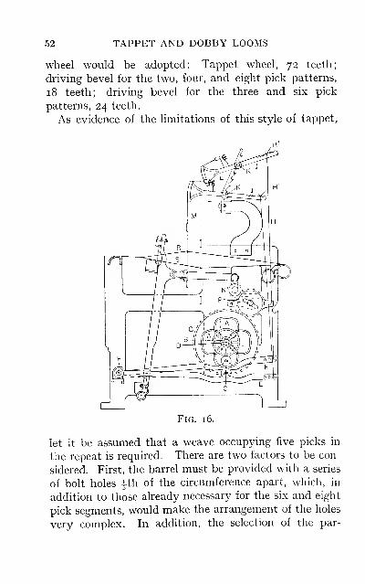
52 TAPPET AND DOBBY LOOMS
wheel would be adopted: Tappet wheel, 72 teeth;
driving bevel for the two, four, and eight pick patterns,
18 teeth; driving bevel for the three and six pick
patterns, 24 teeth.
As evidence of the limitations of this style of tappet,
Fig. 16.
let it be assumed that a weave occupying five picks in
the repeat is required. There are two factors to be con-
sidered. First, the barrel must be provided with a series
of bolt holes 4th of the circumference apart, which, in
addition to those already necessary for the six and eight
pick segments, would make the arrangement of the holes
very complex. In addition, the selection of the par-
BRADFORD TAPPET 53
ticular series of holes required for the various segments
would be a very difficult matter when changing from one
weave to another. Second, the speed at which the barrel
must rotate would require to be different from either of
the two former speeds. This would necessitate a tappet
wheel containing a number of teeth which is a multiple
of five. Similar provision would have to be made for
producing a seven-pick pattern, which, for the reasons
already referred to in connection with the five-pick
pattern, would make it a very difficult matter, if not
altogether impracticable, to produce all these weaves on
the same barrel. It would be much more feasible, if five
and seven pick patterns were required, to have another
barrel tappet to work lo treadles with lo picks to the
round. This would accommodate the five and ten pick
patterns, and have a second set of bolt holes made to
accommodate the seven-pick pattern segments, the
tappet wheel containing 70 teeth, the driving bevels
containing 14 teeth for the five and ten pick patterns,
and 20 teeth for the seven-pick patterns respectively, or
wheels in similar proportions.
Bradford Tappet.—A very common type of shedding
mechanism in which sectional tappets are employed is
illustrated in Fig. 16. This is generally referred to as
the " Bradford tappet," by reason of it being extensively
adopted in that district. The mechanism is placed out-
side the loom frame as shown, and not inside the loom
under the healds as in the former types. The tappets Aare fixed on to the sleeve or tube B, the latter being cast
in one piece with the tappet wheel C. The sleeve is
placed over the end of the low shaft D, which serves as a
stud, on which the sleeve and tappets may revolve.
The treadles E are placed at right angles to the low shaft
;
the heels of the treadles are pivoted at F, and extend for-
ward underneath the tappets. The treadles are pro-
54 TAPPET AND DOBBY LOOMS
vided with an anti-friction bowl G, on which the tappet
impinges. Connection is made indirectly to the heald
shaft by means of the connector rod H, which connects
the end of the treadle to the lever J. This lever in turn
is attached to a square shaft K. These square shafts are
carried in brackets (forming a gantry) , supported by the
top rail of the loom, and extend to such a length as to
allow of two half-moon levers L being placed one at each
side of the heald shaft, to which they are then connected
by the straps M.
The method of working will be understood if some
consideration be given to the throw of the tappet and its
relation to the stroke of the heald shaft and the size of
the shed obtained. The construction of this type of
shedding motion lends itself readily to the formation of
a perfect shed. The throw of the tappet can be regu-
lated to yield the exact amount of movement to the
heald shaft. By careful adjustment of the winged nuts
H^ on the screw thread of the rods H, the correct position
of the heald shaft in relation to the warp line is easily
obtained. The lever J is also provided with a series of
notches about fin. apart. Any alteration of the winged
nut from one notch to another would yield an increased
or decreased stroke of the heald shaft as the length of
the lever J to the half-moon lever is increased or dimin-
ished; by this means the correct depth of the shed is
readily acquired. Let it be assumed that the throw of
the tappet is 3in., the throw being the distance from the
inner circle to the outer circle of the tappet
—
i.e., the
treadle pulley has a stroke of sin.; with other dimen-
sions as follows: Distance from the treadle heel to the
centre of the friction pulley, 24in.; and from friction
pulley to the end of the treadle, I2in.; therefore the
stroke at the end of the treadle will be as 24 : 36 : : 3 : :v,
or X equals 4|in. The winged nut is in the second notch
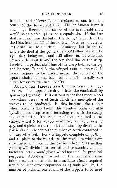
DEPTH OF SHED 55
from the end of lever J, or a distance of gin. from the
centre of the square shaft K. The half-moon lever is
Sin. long; therefore the stroke of the first heald shaft
would be as 9 : 8 : : 4J : ^t, or ::il: equals 4in. If the first
shaft is I2in. from the fell of the cloth, the depth of the
shed 6in. from the fell of the cloth will be as 12 : 6 : : 4 : :v,
or the shed will be 2in. deep. Assuming that the shuttle
enters the shed at this point, this would allow of a shuttle
ifin. deep being used, and still allow Jin. for clearance
between the shuttle and the top shed line of the warp.
To obtain a perfect shed line of the warp both at the top
and bottom, R and S, the winged nuts on the rods Hwould require to be placed nearer the centre of the
square shafts for the back heald shafts—usually one
notch for every two heald shafts.
Driving the Tappets and Change Wheel Calcu-
lation.—The tappets are driven from the crankshaft byspur-wheel gearing. It is customary for the tappet wheel
to contain a number of teeth which is a multiple of the
weaves to be produced. In this instance the tappet
wheel contains 120 teeth, this number being divisible
by all numbers up to and including 10, with the excep-
tion of 7 and 9. The number of teeth required in the
change wheel N for weaves which are complete on 2, 3,
4, 5, and 6 picks to the round, is obtained by dividing the
particular number into the number of teeth contained in
the tappet wheel. For the tappets complete on 7, 8, 9,
and 10 picks to the round, two intermediate wheels are
substituted in place of the carrier wheel P, as neither
7 nor 9 will divide into 120 without remainder, and the
factors 8 and 10 would give a wheel too small for practical
purposes. Adopting a wheel on the crankshaft con-
taining 24 teeth, then the intermediate wheels required
would be in inverse proportion as 24 multiplied by the
number of picks in one round of the tappets to be used
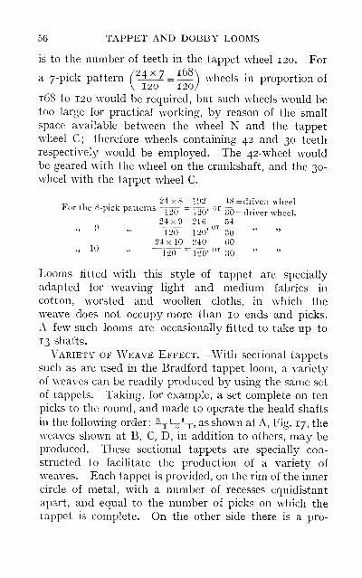
56 TAPPET AND DOBBY LOOMS
is to the number of teeth in the tappet wheel 120. For
a 7-pick pattern /^4 x 7 ^^
—
\ wheels in proportion of
168 to 120 would be required, but such wheels would betoo large for practical working, by reason of the small
space available between the wheel N and the tappet
wheel C; therefore wheels containing 42 and 30 teeth
respectively would be employed. The 42-wheel wouldbe geared with the wheel on the crankshaft, and the 30-
wheel with the tappet wheel C.
^ , o ., 24x8 192 48 = driven wheeltor the S-pick patterns —ToTT = Ton? or ^tt. , .
, ,^ ^ 120 120 dO = driver wheel.24x9 216 54n or
" ^" 120 -120' 30 " "
24 X 10 240 60" ^^ " 120 ~120' ^"^ 30
Looms fitted with this style of tappet are specially
adapted for weaving light and medium fabrics in
cotton, worsted and woollen cloths, in which the
weave does not occupy more than 10 ends and picks.
A few such looms are occasionally fitted to take up to
13 shafts.
Variety of Weave Effect.—With sectional tappets
such as are used in the Bradford tappet loom, a variety
of weaves can be readily produced by using the same set
of tappets. Taking, for example, a set complete on ten
picks to the round, and made to operate the heald shafts
in the following order: -y -ir-y ^s shown at A, Fig. 17, the
weaves shown at B, C, D, in addition to others, may beproduced. These sectional tappets are specially con-
structed to facilitate the production of a variety of
weaves. Each tappet is provided, on the rim of the inner
circle of metal, with a number of recesses equidistant
apart, and equal to the number of picks on which the
tappet is complete. On the other side there is a pro-
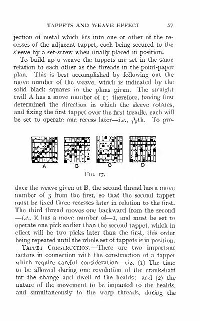
TAPPETS AND WEAVE EFFECT 57
jection of metal which fits into one or other of the re-
cesses of the adjacent tappet, each being secured to the
sleeve by a set-screw when finally placed in position.
To build up a w^eave the tappets are set in the same
relation to each other as the threads in the point-paper
plan. This is best accomplished by following out the
move number of the weave, which is indicated by the
solid black squares in the plans given. The straight
twill A has a move number of i ; therefore, having first
determined the direction in which the sleeve rotates,
and fixing the first tappet over the first treadle, each will
be set to operate one recess later
—
i.e., jV^^- ^^ P^^"
I* 1 |« U|« 1
58 TAPPET AND DOBBY LOOMS
formation of the next shed. With reference to the
former, in looms which are employed to weave a variety
of cloths it is essential that allowance be made so that
the relation of the timing of the shedding to the beating-
up of the weft may be varied. There are three main
reasons for this procedure:
(a) To Facilitate Heavy Wefting.—When weaving
cloths in which it is desired to insert the maximumnumber of picks per inch of any given count of yarn, it is
more easily effected by beating up the weft in a crossed
shed, than with the shed partly crossed. It will be
obvious that if the weft is pushed into position with the
next shed nearly or fully formed, it will be prevented
from springing back from the preceding pick, by reason
of the warp threads closing over it and locking it in
position. Another advantage is that a given numberof picks can be put into a cloth with less weight on the
warp beam, and consequently with less strain on the
warp. A defect sometimes attendant upon early shed-
ding, and resulting in excessive chafing and breakages
of the warp, is due to the weft being forced into position
through the crossed shed. This defect is chiefly en-
countered when weaving single woollen yarn, warps
slackly twisted, and warps inadequately sized or un-
sized.
(b) Clearing the Shed.—Early shedding is occa-
sionally practised in order to assist in clearing the shed
when weaving cloths in which the warp is made from
coarse cross-bred worsted or low cheviot woollen yarn.
Such warps have a quantity of loose and projecting fibre,
the natural tendency being for these to interlock with
each other, or to roll up into bead form, and as a result
prevent the formation of a clear shed. It will probably
be remarked that sizing the warp is a sufficient remedy
for this defect. But let it be assumed that an attempt
CLEARING THE SHED 59
is made to weave this class of warp without sizing.
Such warps are usuahy strong enough to resist the strain
to which they are subject during weaving. To size
them solely for laying the loose and projecting fibres,
appears to be a somewhat unnecessary and expensive
operation. The cost of production is also increased on
account of the outlay in sizing plant, material, and
labour involved in the process. In order to separate
any adhering fibres, the shed should be timed as early as
possible; with the opening of the shed the threads are
subject to a degree of tension, and as further strain is
suddenly applied at the beat-up, it helps to clear the shed
for the passage of the shuttle. Other methods occasion-
ally adopted with advantage are as follows : Weaving with
the warp as tight as possible; bringing the lease rods
nearer the back of the healds; fixing clasp laths on the
warp midway between the healds and the back rest;
weaving with the warp running through two reeds ; andtying a thrum roller behind the slay to roll upon the top
shed line of warp to collect up the loose fibres. In
tappet looms the tappets may be constructed to give a
long dwell and a short time for the change, with a uni-
form movement imparted to the heald. Any of the
above methods may also be applied with advantage
when weaving cords, corkscrews, and satins, the shed
with these being difficult to clear, resulting in numerousweft staples in the piece.
(c) Early Shedding, in combination with the
principle of troughing the shed, is employed for the
prevention of reed marks and obtaining cover. This
principle is further considered on page 98.
The allowance for the timing of the shed is determined
by the construction of the tappet. The first factor to
decide is the minimum dwell that can be given to the
healds. This dwell in some instances is calculated to a
60 TAPPET AND DOBBY LOOMS
degree of accuracy which eventuaUy proves to be detri-
mental to the working of the loom. If the time taken
for the passage of the shuttle is equal to a fourth of the
crank's revolution, a pause of not less than this time
must be allowed for the dwell of the heald. This would
leave the maximum time for the change, with the ad-
vantage of slower motion and less strain on the warp.
It is evident that under such conditions the beat-up will
always take place with the healds in the same position
—
i.e., the shed at the same point of formation. Anydeviation from this condition is only possible by effect-
ing an alteration in the proportion of time to be allowed
for the change and dwell. This extreme is rarely carried
beyond allowing half a revolution of the crank for the
change and dwell respectively. The healds may then
be set in any position between the extremes as shown in
Fig. 10.
Method of Drawing the Outline of a Tappet.—The method of construction is further illustrated in Fig.
i8. To draw the outline of the tappet required for the
interlacing given in Fig. 17, the following additional
particulars are required: Diameter of treadle pulley,
3in.; diameter of inner circle, 6in.; throw of the tappet,
3in. Proceed as follows: With the radius of the inner
circle describe the circle A ; to this radius add the throw
of the tappet and describe the outer circle B. The com-
pleted outline of the tappet will run on or between these
two circles. To obtain the contour of the centre of the
treadle pulley, which will be i Jin. from the outline of the
tappet, describe the two construction circles C and D.
These are obtained by adding the radius of the pulley,
I Jin., to the radius of the two circles A, B already
described. Next divide the four circles by radial lines
into as many sections as there are picks in the weave for
which the tappet is required—in this instance ten, de-
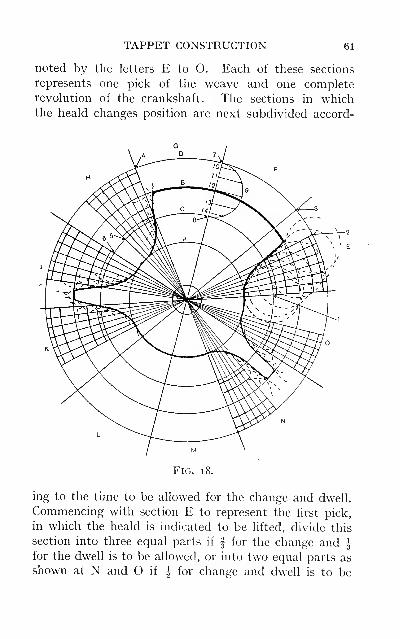
TAPPET CONSTRUCTION 61
noted by the letters E to O. Each of these sections
represents one pick of the weave and one complete
revolution of the crankshaft. The sections in whichthe heald changes position are next subdivided accord-
FiG. 1 8.
ing to the time to be allowed for the change and dwell.
Commencing with section E to represent the first pick,
in which the heald is indicated to be lifted, divide this
section into three equal parts if | for the change and ^for the dwell is to be allowed, or into two equal parts as
shown at N and O if J for change and dwell is to be
62 TAPPET AND DOBBY LOOMS
allowed. It will, of course, be understood that the time
allowed for the change and dwell must be the same in
each section, in the actual construction of a tappet.
The line followed by the centre of the pulley will pass
from point i to 2, and continue for the dwell on the
circle D up to point 3. As the heald is required to be
lifted for three picks in succession, the line is continued
through sections F and G up to point 4. The heald nowchanges position, the line being continued through the
frds division of section H down to point 5 and continued
on the circle C up to point 6. The heald then again
changes, the line passing from the circle C to the circle Das before, but this time for one section only. It then
passes to the circle C, on which it is continued for three
successive sections K, L, and M. It next passes to the
circle D for one section only, then back to circle C for
the remaining section O, and subsequently up to the
starting point i.
Nature of the Motion Desirable for the Healds.—If it is desired to impart a uniform motion to the healds
when changing position, this can be obtained by joining
the points i and 2 where the several changes take place,
by means of a straight line. But an eccentric, and not a
uniform, motion is necessary, so that the healds maycommence changing slowly, increasing in speed towards
the middle of their traverse, and then diminishing in
inverse ratio to the finish. The outline to be followed
by the centre of the pulley during the change, in order
to transmit an eccentric motion to the heald, is obtained
as follows: Divide that portion of the several sections
allowed for the change by means of radial lines, into a
number of equal parts
—
e.g., six. Next divide the space
between the construction circles C, D into the same
number of parts, but unequal. This may be done by
dividing the line 7, 8 in arithmetical progression, or by
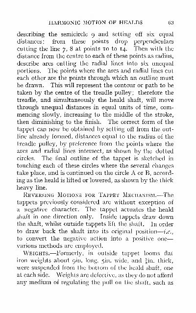
HARMONIC MOTION OF HEALDS 63
describing the semicircle 9 and setting off six equal
distances; from these points drop perpendiculars
cutting the line 7, 8 at points 10 to 14. Then with the
distance from the centre to each of these points as radius,
describe arcs cutting the radial lines into six unequal
portions. The points where the arcs and radial lines cut
each other are the points through which an outline mustbe drawn. This will represent the contour or path to be
taken by the centre of the treadle pulley; therefore the
treadle, and simultaneously the heald shaft, will movethrough unequal distances in equal units of time, com-
mencing slowly, increasing to the middle of the stroke,
then diminishing to the finish. The correct form of the
tappet can now be obtained by setting off from the out-
line already formed, distances equal to the radius of the
treadle pulley, by preference from the points where the
arcs and radial lines intersect, as shown by the dotted
circles. The final outline of the tappet is sketched in
touching each of these circles where the several changes
take place, and is continued on the circle A or B, accord-
ing as the heald is lifted or lowered, as shown by the thick
heavy line.
Reversing Motions for Tappet Mechanism.—Thetappets previously considered are without exception of
a negative character. The tappet actuates the heald
shaft in one direction only. Inside tappets draw downthe shaft, whilst outside tappets lift the shaft. In order
to draw back the shaft into its original position
—
i.e.,
to convert the negative action into a positive one
—
various methods are employed.
Weights.—Formerly, in outside tappet looms flat
iron weights about gin. long, 5in. wide, and fin. thick,
were suspended from the bottom of the heald shaft, one
at each side. Weights are defective, as they do not afford
any medium of regulating the pull on the shaft, such as
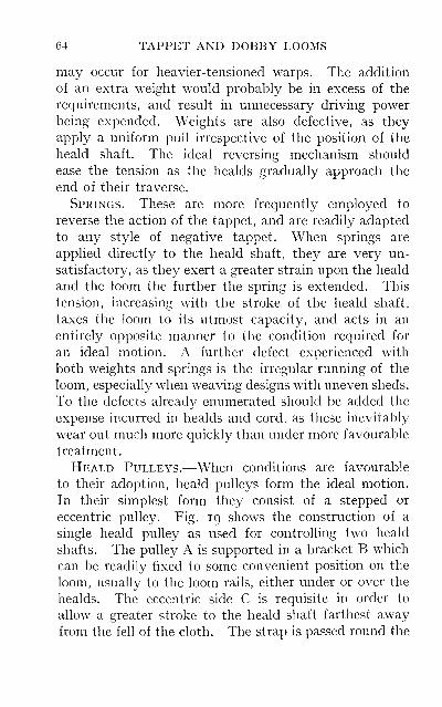
64 TAPPET AND DOBBY LOOMS
may occur for heavier-tensioned warps. The addition
of an extra weight would probably be in excess of the
requirements, and result in unnecessary driving powerbeing expended. Weights are also defective, as they
apply a uniform pull irrespective of the position of the
heald shaft. The ideal reversing mechanism should
ease the tension as the healds gradually approach the
end of their traverse.
Springs.—These are more frequently employed to
reverse the action of the tappet, and are readily adapted
to any style of negative tappet. When springs are
applied directly to the heald shaft, they are very un-
satisfactory, as they exert a greater strain upon the heald
and the loom the further the spring is extended. This
tension, increasing with the stroke of the heald shaft,
taxes the loom to its utmost capacity, and acts in an
entirely opposite manner to the condition required for
an ideal motion. A further defect experienced with
both weights and springs is the irregular running of the
loom, especially when weaving designs with uneven sheds.
To the defects already enumerated should be added the
expense incurred in healds and cord, as these inevitably
wear out much more quickly than under more favourable
treatment.
Heald Pulleys.—When conditions are favourable
to their adoption, heald pulleys form the ideal motion.
In their simplest form they consist of a stepped or
eccentric pulley. Fig. 19 shows the construction of a
single heald pulley as used for controlling two heald
shafts. The pulley A is supported in a bracket B which
can be readily fixed to some convenient position on the
loom, usually to the loom rails, either under or over the
healds. The eccentric side C is requisite in order to
allow a greater stroke to the heald shaft farthest awayfrom the fell of the cloth. The strap is passed round the
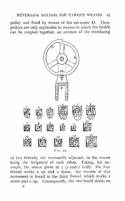
REVERSING MOTIONS FOR VARIOUS WEAVES 65
pulley and fixed by means of the set-screw D. These
pulleys are only applicable to weaves in which the healds
can be coupled together, on account of the interlacing
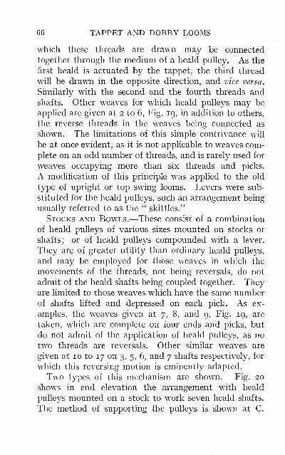
66 TAPPET AND DOBBY LOOMS
which these threads are drawn may be connected
together through the medium of a heald pulley. As the
first heald is actuated bj^ the tappet, the third thread
will be drawn in the opposite direction, and vice versa.
Similarly with the second and the fourth threads andshafts. Other weaves for which heald pulleys may be
applied are given at 2 to 6, Fig. 19, in addition to others,
the reverse threads in the weaves being connected as
shown. The limitations of this simple contrivance will
be at once evident, as it is not applicable to weaves com-
plete on an odd number of threads, and is rarely used for
weaves occupying more than six threads and picks.
A modification of this principle was applied to the old
type of upright or top swing looms. Levers were sub-
stituted for the heald pulleys, such an arrangement being
usually referred to as the " skittles."
Stocks and Bowls.—These consist of a combination
of heald pulleys of various sizes mounted on stocks or
shafts; or of heald pulleys compounded with a lever.
They are of greater utility than ordinary heald pulleys,
and may be employed for those weaves in which the
movements of the threads, not being reversals, do not
admit of the heald shafts being coupled together. Theyare limited to those weaves w^hich have the same numberof shafts lifted and depressed on each pick. As ex-
amples, the weaves given at 7, 8, and 9, Fig. 19, are
taken, which are complete on four ends and picks, but
do not admit of the application of heald pulleys, as no
two threads are reversals. Other similar weaves are
given at 10 to 17 on 3, 5, 6, and 7 shafts respectively, for
which this reversing motion is eminently adapted.
Two types of this mechanism are shown. Fig. 20
shows in end elevation the arrangement with heald
pulleys mounted on a stock to work seven heald shafts.
The method of supporting the pulleys is shown at C.
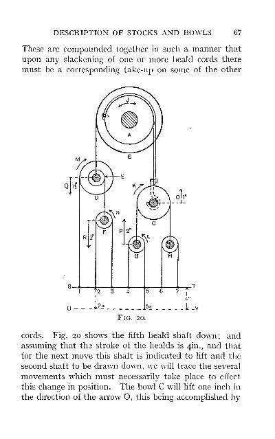
DESCRIPTION OF STOCKS AND BOWLS 67
These are compounded together in such a manner that
upon any slackening of one or more heald cords there
must be a corresponding take-up on some of the other
Fig. 20.
cords. Fig. 20 shows the fifth heald shaft down; andassuming that tha stroke of the healds is 4in., and that
for the next move this shaft is indicated to lift and the
second shaft to be drawn down, we will trace the several
movements which must necessarily take place to effect
this change in position. The bowl C will lift one inch in
the direction of the arrow O, this being accomplished by
68 TAPPET AND DOBBY LOOMS
A B turning in the direction indicated by the arrow J.
The result of such a movement would be to lift the bowls
H and G one inch each ; but the bowl H is held in posi-
tion by the tight heald cords 6 and 7. Therefore the
giving-out movements can only be effected through the
bowl G, which is lifted one inch by the rising of bowl C,
and another inch by reason of this bowl being turned in
the direction of the arrow K. As the bowl G is raised
2in. in the direction of the arrow P, the heald cords 4and 5 should each give out 2in. ; but the heald cord 4 is
tight, and by reason of this will turn the bowl G in the
direction of the arrow L to take up the remaining 2in.
of the slack cord 5
—
^a. Next trace out the compen-
sating movement which takes place in the bowls D and Fin order to allow the heald shaft No. 2 to be lowered.
The diameters of the stepped pulleys A and B are in
the proportion of 3 to 4, so that the bowl D will be
lowered ijin. as at Q. This causes a slackening of the
heald cords i, 2, and 3 to the extent of ijin. each, but
the shaft 2 only can move, and that 4in. As the heald
cord 2 is drawn in the direction of 2a it will take up ijin.,
and also draw the bowl F round in the direction of the
arrow N to take up the ijin. of the heald cord 3. At the
same time, it will draw round the stepped bowl D E bypulling at the small step E to the extent of fin. This
allows the bowl F to be lowered, yielding fin. of slack
cord to each of the healds 2 and 3; but this slack is
taken up by the heald shaft 2, which is only drawn down.
The compensating movement between the two stepped
bowls E and D, the proportions of which are as i to 2,
results in their turning in the direction of the arrow Mand taking up the ijin. given out to the first heald
attendant upon the lowering of the bowl D. Whenstocks and bowls are employed for weaves which occupy
an odd number of shafts, it is of the utmost importance
LIMITATIONS OF REVERSING MOTIONS 69
that the diameters of the stepped pulleys should be in
correct proportion to each other, otherwise there will be
undue strain placed upon the heald cords, in addition to
a defective shed being formed. The greater leverage is
always relegated to the side from which the smaller
number of shafts are suspended, as shown in Fig. 20, the
proportions being determined by the number of shafts
on which the weave is complete.
Fig. 21 illustrates an alternative method of com-
pounding the bowls with a lever. The lever A is sup-
ported in the bracket B, which is fixed to the loom rail
by means of the hand-screw C. The bowl D is carried
in the block E pivoted to the lever A. Provision is
made for attaching other pulley blocks at F, G, H. This
method possesses an advantage over the stepped bowls
fixed to a stock, for the following reason. The propor-
tions of leverage are more readily obtained when re-
quired for weaves occupying an odd number of shafts.
The respective distances are shown along the line J K,
the connections being more easily adjusted according to
requirements. Tw^o sets of bowls, as shown in Fig. 20,
used in combination with the lever illustrated in Fig. 21,
could be so arranged as to serve for all weaves, complete
on any number of threads up to eight, provided that the
same number of shafts are lifted and depressed on each
pick.
It will be observed that of the several types of reversing
motions already dealt with no single motion is applicable
to every order of interlacing or variety of weave. Somerestriction is imposed with each type that prevents its
general adoption.
Kenyon's and Similar Under-motions.—Whilst
one or other of the former methods employed for re-
versing the heald could be utilised for the majority of
weaves produced on the negative tappet loom, some pro-
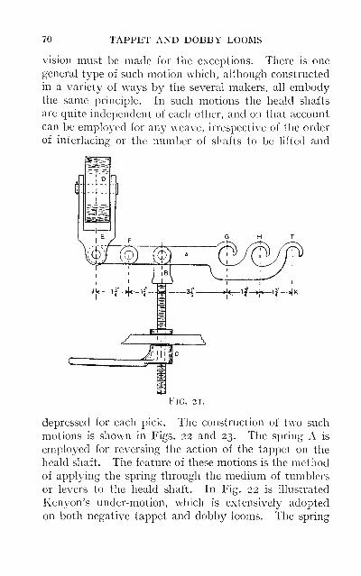
70 TAPPET AND DOBBY LOOMS
vision must be made for the exceptions. There is one
general type of such motion which, although constructed
in a variety of ways by the several makers, all embodythe same principle. In such motions the heald shafts
are quite independent of each other, and on that account
can be employed for any weave, irrespective of the order
of interlacing: or the number of shafts to be lifted and
Fig. 21.
depressed for each pick. The construction of two such
motions is shown in Figs. 22 and 23. The spring A is
employed for reversing the action of the tappet on the
heald shaft. The feature of these motions is the methodof applying the spring through the medium of tumblers
or levers to the heald shaft. In Fig. 22 is illustrated
Kenyon's under-motion, which is extensively adopted
on both negative tappet and dobby looms. The spring

KENYOX'S UNDER-MOTION 71
is not applied directly to the heald shaft, but is used in
combination with the specially constructed tumblers
B. These tumblers are fulcrumed on the stud C, the
stud D serving as a check pin to the tumbler when the
latter is drawn back. The studs are suitably carried in
the chairs E, which may be pushed further apart or
drawn closer together by means of the expansion bolts
F for the purpose of increasing or decreasing the power
of the spring on the heald shaft. The tumblers are also
Fig. 22.
provided with two hooks G and H, on to either of which
the spring may be attached, or, as is occasionally re-
quired for heavy goods, two springs may be attached to
the same tumbler. This type of motion when applied to
tappet looms is constructed with one layer of springs to
work up to ten shafts; when employed for single-action
dobbies it can be obtained with two sets of tumblers and
two layers of springs. The chief feature of this and
similar motions is the mechanical advantage derived
from the method of applying the spring. The spring
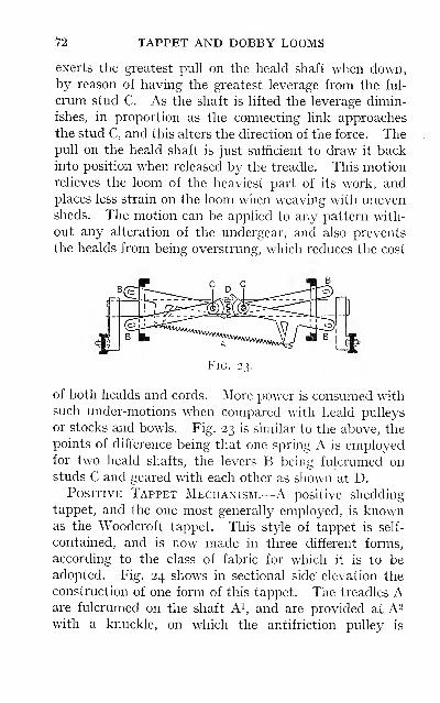
n TAPPET AND DOBBY LOOMS
exerts the greatest pull on the heald shaft when down,by reason of having the greatest leverage from the ful-
crum stud C. As the shaft is lifted the leverage dimin-
ishes, in proportion as the connecting link approaches
the stud C, and this alters the direction of the force. Thepull on the heald shaft is just sufficient to draw it backinto position when released by the treadle. This motionrelieves the loom of the heaviest part of its work, andplaces less strain on the loom when weaving with unevensheds. The motion can be applied to any pattern with-
out any alteration of the undergear, and also prevents
the healds from being overstrung, which reduces the cost
Fig. 23.
of both healds and cords. More power is consumed withsuch under-motions when compared with heald pulleys
or stocks and bowls. Fig. 23 is similar to the above, the
points of difference being that one spring A is employedfor two heald shafts, the levers B being fulcrumed onstuds C and geared with each other as shown at D.
Positive Tappet Mechanism.—A positive shedding
tappet, and the one most generally employed, is knownas the Woodcroft tappet. This style of tappet is self-
contained, and is now made in three different forms,
according to the class of fabric for which it is to beadopted. Fig. 24 shows in sectional side' elevation the
construction of one form of this tappet. The treadles Aare fulcrumed on the shaft A^, and are provided at A^with a knuckle, on which the antifriction pulley is
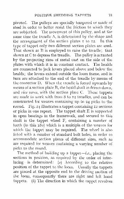
POSITIVE SHEDDING TAPPETS 73
pivoted. The pulleys are specially tempered or made of
steel in order to better resist the friction to which they
are subjected. The movement of this pulley, and at the
same time the treadle A, is determined by the shape and
the arrangement of the section plates i to 12. In this
type of tappet only two different section plates are used.
That shown at B is employed to raise the treadle; that
shown at C to depress the treadle. The pulley is actuated
by the projecting rims of metal cast on the side of the
plates with which it is in constant contact. The healds
are connected to jack levers placed above and below the
healds ; the levers extend outside the loom frame, and in
turn are attached to the end of the treadle by means of
the connector D. When the treadle is forced upwards bymeans of a section plate B, the heald shaft is drawn down,
and vice versa, with the section plate C. These tappets
are made to work with from 8 to 12 treadles, and can be
constructed for weaves containing up to 24 picks to the
round. Fig. 24 illustrates a tappet containing 12 sections
or picks in one repeat. The tappet shaft E is supported
in open bearings in the framework, and secured to this
shaft is the tappet wheel F, containing a number of
teeth (in this 180) which is a multiple of the weaves for
which the tappet may be required. The wheel is also
fitted wdth a number of standard bolt holes, in order to
accommodate section plates of different sizes, such as
are required for weaves containing a varying number of
picks to the round.
The method of building up a tappet
—
i.e., placing the
sections in position, as required by the order of inter-
lacing—is determined: (a) According to the relative
position of the tappet to the loom. Usually the tappets
are placed at the opposite end to the driving motion of
the loom, consequently there are right and left handtappets, (b) The direction in which the tappet revolves
74 TAPPET AND DOBBY LOOMS
must also be considered before commencing to place the
section plates in position. The tappet is driven direct
from the crankshaft by means of a spur wheel, or by a
spur and pinion wheel, to facilitate changing the speed
of the tappet as occasion may arise, when changing to a
weave containing a different number of picks to the
round
—
e.g., from a 12 to a 9 pick pattern. When the
above factors are carefully considered little difficulty is
experienced in building up a tappet to produce any given
weave. The real difficulty is encountered when after
the completion of, say, a 12 x 12 pick pattern a mistake
is discovered in the working of one or other of the treadles.
This necessitates pulling down the tappet as far as the
defect to again rebuild.
To build up a tappet for the order of interlacing as
given at G, a convenient number of bolts are first passed
through the tappet wheel, and not one bolt for each
section plate. The first order of working to be built upis for the last thread in the design, on account of the
treadle nearest the tappet wheel actuating the back
heald shaft. The first section plate as indicated by a
mark on the first pick of the last thread is a lifter C.
The tappet revolving in the direction of the arrow, the
next section plate will be placed to the left of this, and
which from the reading of the second pick on the last
thread must be a sinker B. The section plates being
slightly dovetailed at their edges help to keep each other
in position until the full complement of plates for operat-
ing the first treadle have been fixed as shown from Nos.
I to 12 on the tappet. A ring plate, shown shaded
with projecting rims of metal fitting into the correspond-
ing recesses on the section plates, is then placed to keep
the sections in position. The above order is repeated
for the working of the next treadle, which controls the
working of the last thread but one in the design. This
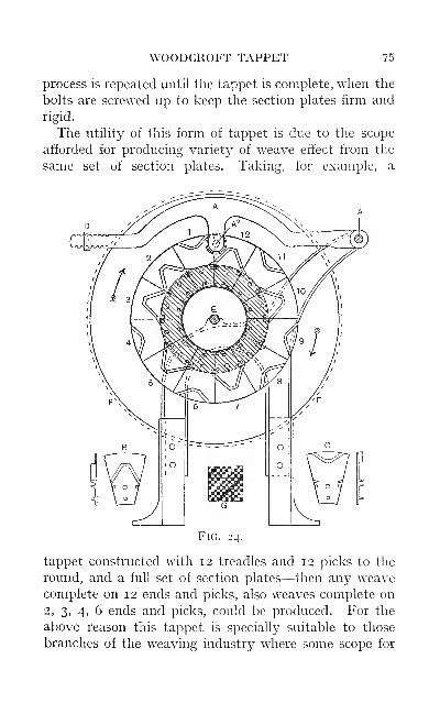
WOODCROFT TAPPET 75
process is repeated until the tappet is complete, when the
bolts are screwed up to keep the section plates firm and
rigid.
The utility of this form of tappet is due to the scope
afforded for producing variety of weave effect from the
same set of section plates. Taking, for example, a
Fig. 24.
tappet constructed with 12 treadles and 12 picks to the
round, and a full set of section plates—then any weavecomplete on 12 ends and picks, also weaves complete on
2, 3, 4, 6 ends and picks, could be produced. For the
above reason this tappet is specially suitable to those
branches of the weaving industry where some scope for
76 TAPPET AND DOBBY LOOMS
weave effect is desirable. It has been largely used in
connection with cotton weaving, but is now being super-
seded by the dobby. The style of shed produced is
known as " centre closed "—that is, the healds are all
brought back to the centre line after the insertion of
each pick. This factor makes this type of tappet useful
for the production of the simple styles of leno and gauze
effects. Another form of this tappet is obtained bymaking the section plate in one solid piece, and not built
up of separate sections. This form of tappet is often
referred to as the box tappet, and is no doubt muchbetter than the former, if it is required to be kept on one
particular weave. When made in this form there is no
possibility of the sections working loose; therefore it is
eminently suitable for heavy work, notably the heavy
builds of woollen and cotton cords, corduroys, fustians,
etc.
A third form of this tappet is that now made to pro-
duce open shedding—that is, the healds remain lifted or
depressed for the requisite number of picks; only those
threads move which have to change their position for
the next pick. If, for example, the weave is a simple
twill, complete on six ends and picks, each thread work-
ing \, the healds when once lifted or depressed would
remain in that position for three successive picks. This
form of tappet is well adapted for weaving light and
medium fabrics. To produce open shedding, duplicates
of eight different section plates are necessary, as com-
pared with duplicates of two section plates in the former
tappet. The main advantage of each of these forms of
tappet is attributed to the fact that when once the
pattern is correctly built up, that pattern will be pro-
duced without any danger of lost, broken, or short pegs,
and other causes incidental to heald missings in dobby
looms.
CHAPTER IV
DOBBY MECHANISM
With the object of obtaining increased figuring capacity
in pattern production, beyond what is possible by the
use of tappets, dobbies are employed. In this respect
the dobby loom occupies a medium position between the
tappet and the jacquard loom. There are several well-
known types of dobby mechanism in general use, ranging
in their capacity from i6 up to 48 heald shafts, which are
practically unlimited in the number of picks a pattern
may occupy. The capacity of the dobby varies with the
type of loom according to the class of fabric for whichit is to be utilised. The style of cloths chiefly produced
in some districts is such as to require a dobby ranging
from 16 up to 24 shafts. Again, taking the fancy
worsted and woollen trade of Huddersfield, and districts
where similar goods are produced, a dobby ranging from
24 up to 36 shafts is adopted, whilst in the fancy dress-
goods trade the capacity of the dobby extends up to 48shafts. The mechanism of dobbies may be divided for
comparison into two classes, referred to as the wheel
dobby and the lever dobby, of which the Hollingworth
and Knowles and the Keighley dobbies are typical ex-
amples. The former class until recently has been the
exclusive production of the Dobcross loom makers.
It has now, however, a rival, in a new loom made byMessrs George Hodgson Limited, Bradford, who haveintroduced this principle of shedding in their loom.
The " Keighley " dobby, the invention of Messrs Hatters-
77
78 TAPPET AND DOBBY LOOMS
ley and Sons, is now made in various forms by several
well-known dobby and loom makers.
An illustration of the principle parts in the Holling-
worth and Knowles dobby is shown in side elevation in
Fig. 25. The healds are connected to the jack J as
follows: From the upper arm J^ connection is made to
the top of the heald shaft by means of streamer wires
and straps which are carried over heald pulleys. The
heald shaft is connected from the bottom by means of
under] acks and streamer rods up to the lower arm J^ of
the jack. The jacks are made with an open bearing,
which admits of their easy removal, and are provided
with notches into which the connecting links are placed,
according to the depth of shed required and the position
the heald shaft occupies in the set of healds. To increase
the facility for obtaining a gradually sloping shed in a
36-heald dobby, the jacks are made in three sizes, 12
jacks of each size. This provides ample scope for ad-
justing the stroke of the heald shafts farthest away
from the feh of the cloth, there being a range of 17
notches from the first notch in the shortest jack to
the last notch in the longest jack. The jack is
provided with a knuckle joint at J^, on which fits the
forked end of the connector C ; the other end of the con-
nector is also made with an opening to admit the vibrator
V, to which it is pivoted. The vibrator is a toothed disc
with the teeth arranged in the order: 17 teeth, then one
tooth missed, 17 teeth, then four teeth missed. It is
also provided with a radial slot S, the extremity of which
comes in contact with a bowl U fixed in the lever H, the
purpose of which is to arrest the vibrator in the same
relative position after being turned over in either direc-
tion. The vibrator is supported at its centre T on a bowl
in the vibrator lever, which is provided with an aperture
for this purpose. A pulley slip or shoe is fixed in the
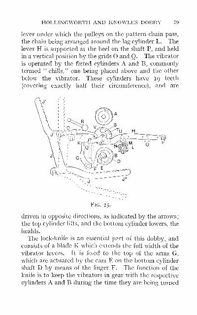
HOLLINGWORTH AND KNOWLES DOBBY 79
lever under which the pulleys on the pattern chain pass,
the chain being arranged around the lag cylinder L. Thelever H is supported at the heel on the shaft P, and held
in a vertical position by the grids O and Q. The vibrator
is operated by the fluted cylinders A and B, commonlytermed " chills," one being placed above and the other
below the vibrator. These cylinders have 19 teeth
(covering exactly half their circumference), and are
Fig. 25.
driven in opposite directions, as indicated by the arrows
;
the top cylinder lifts, and the bottom cylinder lowers, the
healds.
The lock-knife is an essential part of this dobby, and
consists of a blade K which extends the full width of the
vibrator levers. It is fixed to the top of the arms G,
which are actuated by the cam E on the bottom C3dinder
shaft D by means of the finger F. The function of the
knife is to keep the vibrators in gear with the respective
cylinders A and B during the time they are being turned
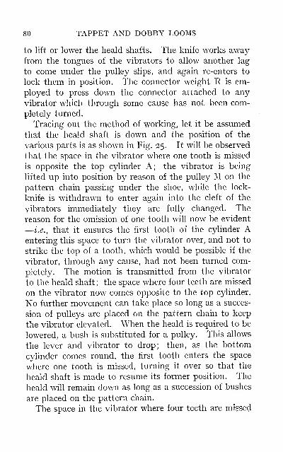
80 TAPPET AND DOBBY LOOMS
to lift or lower the heald shafts. The knife works awayfrom the tongues of the vibrators to allow another lag
to come under the pulley slips, and again re-enters to
lock them in position. The connector weight R is em-
ployed to press down the connector attached to any
vibrator which through some cause has not been com-
pletely turned.
Tracing out the method of working, let it be assumed
that the heald shaft is down and the position of the
various parts is as shown in Fig. 25. It will be observed
that the space in the vibrator where one tooth is missed
is opposite the top cylinder A; the vibrator is being
lifted up into position by reason of the pulley M on the
pattern chain passing under the shoe, while the lock-
knife is withdrawn to enter again into the cleft of the
vibrators immediately they are fully changed. The
reason for the omission of one tooth will now be evident
—i.e., that it ensures the first tooth of the cylinder Aentering this space to turn the vibrator over, and not to
strike the top of a tooth, which would be possible if the
vibrator, through any cause, had not been turned com-
pletely. The motion is transmitted from the vibrator
to the heald shaft ; the space where four teeth are missed
on the vibrator now comes opposite to the top cylinder.
No further movement can take place so long as a succes-
sion of pulleys are placed on the pattern chain to keep
the vibrator elevated. When the heald is required to be
lowered, a bush is substituted for a pulley. This allows
the lever and vibrator to drop; then, as the bottom
cylinder comes round, the first tooth enters the space
where one tooth is missed, turning it over so that the
heald shaft is made to resume its former position. The
heald wih remain down as long as a succession of bushes
are placed on the pattern chain.
The space in the vibrator where four teeth are missed

TIMING AND SETTING 81
is always left opposite the cylinder by which it was last
turned. The style of shed produced is the " open shed,"
due to the healds remaining up or down for the requisite
number of picks, a factor which facilitates high speeds
being attained.
Timing and Setting.—The successful working of this
dobby is dependent upon the judicious timing of the
various parts in relation to each other. One of the
special advantages of this dobby is that which affords
a ready means for timing the shedding motion to the
beat-up, for reasons already stated. This is accom-
plished by setting the cylinders A and B, which con-
trol the healds, from being level with the boxsection, or as many as seven teeth in advance of it,
according to requirements. It is the usual practice to
set the heald section five teeth in advance of the box
section, and allow them to remain in that position for
all classes of work. This is a questionable practice, and
unless early shedding is resorted to for the purpose of
clearing the shed {see page 58), the following setting
should be adopted. Set the heald section in line with the
box section for light work, four teeth in advance for
medium work, and seven teeth in advance of box section
for heavy work, which is the maximum. When setting
the cylinders it is important to have the first tooth of
each engaging with respective vibrators exactly at the
same time. The limitation of setting is governed by the
shape or throw of the cam E. It is obvious that the
lock-knife must remain in contact with the vibrator
levers until the vibrators in both the heald and boxsections are completely turned. This time will be equal
to half a revolution of the cylinders when they are set
level, or two-thirds if set seven teeth in advance; there-
fore the dimensions of the cam must be made to corre-
spond with this latter setting. This leaves the minimumF
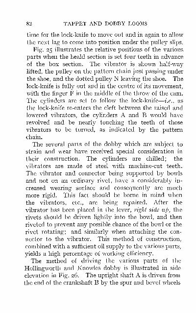
82 TAPPET AND DOBBY LOOMS
time for the lock-knife to move out and in again to allow
the next lag to come into position under the pulley slips.
Fig. 25 illustrates the relative positions of the various
parts when the heald section is set four teeth in advance
of the box section. The vibrator is shown half-way
lifted, the pulley on the pattern chain just passing under
the shoe, and the dotted pulley N leaving the shoe. Thelock-knife is fully out and in the centre of its movement,with the finger F in the middle of the throw of the cam.
The cylinders are set to follow the lock-knife
—
i.e., as
the lock-knife re-enters the cleft between the raised andlowered vibrators, the cylinders A and B would have
revolved and be nearly touching the teeth of those
vibrators to be turned, as indicated by the pattern
chain.
The several parts of the dobby which are subject to
strain and wear have received special consideration in
their construction. The cylinders are chilled; the
vibrators are made of steel with machine-cut teeth.
The vibrator and connector being supported by bowls
and not on an ordinary rivet, have a considerably in-
creased wearing surface and consequently are muchmore rigid. This fact should be borne in mind w^hen
the vibrators, etc., are being repaired. After the
vibrator has been placed in the lever, right side iip, the
rivets should be driven lightly into the bowl, and then
riveted to prevent any possible chance of the bowl or the
rivet rotating; and similarly when attaching the con-
nector to the vibrator. This method of construction,
combined with a sufficient oil supply to the various parts,
yields a high percentage of working efficiency.
The method of driving the various parts of the
HoUingworth and Knowles dobby is illustrated in side
elevation in Fig. 26. The upright shaft A is driven from
the end of the crankshaft B by the spur and bevel wheels
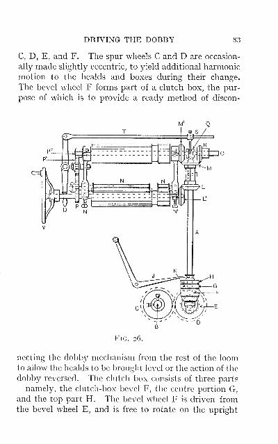
DRIVING THE DOBBY 83
C, D, E, and F. The spur wheels C and D are occasion-
ally made slightly eccentric, to yield additional harmonic
motion to the healds and boxes during their change.
The bevel wheel F forms part of a clutch box, the pur-
pose of which is to provide a ready method of discon-
FiG. 26.
necting the dobby mechanism from the rest of the loomto allow the healds to be brought level or the action of the
dobby reversed. The clutch box consists of three parts
—namely, the clutch-box bevel F, the centre portion G,
and the top part H. The bevel wheel F is driven fromthe bevel wheel E, and is free to rotate on the upright
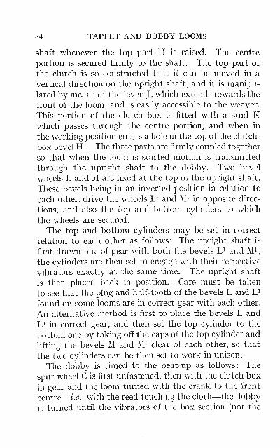
84 TAPPET AND DOBBY LOOMS
shaft whenever the top part H is raised. The centre
portion is secured firmly to the shaft. The top part of
the clutch is so constructed that it can be moved in a
vertical direction on the upright shaft, and it is manipu-
lated by means of the lever J , which extends towards the
front of the loom, and is easily accessible to the weaver.
This portion of the clutch box is fitted with a stud Kwhich passes through the centre portion, and when in
the working position enters a hole in the top of the clutch-
box bevel H. The three parts are firmly coupled together
so that when the loom is started motion is transmitted
through the upright shaft to the dobby. Two bevel
wheels L and M are fixed at the top of the upright shaft.
These bevels being in an inverted position in relation to
each other, drive the wheels U and M^ in opposite direc-
tions, and also the top and bottom cylinders to which
the wheels are secured.
The top and bottom cylinders may be set in correct
relation to each other as follows: The upright shaft is
first drawn out of gear with both the bevels L^ and M^
;
the cylinders are then set to engage with their respective
vibrators exactly at the same time. The upright shaft
is then placed back in position. Care must be taken
to see that the plug and half-tooth of the bevels L and L^
found on some looms are in correct gear with each other.
An alternative method is first to place the bevels L and
U in correct gear, and then set the top cylinder to the
bottom one by taking off the caps of the top cylinder and
lifting the bevels M and M^ clear of each other, so that
the two cylinders can be then set to work in unison.
The dobby is timed to the beat-up as foUows: The
spur wheel C is first unfastened, then with the clutch box
in gear and the loom turned with the crank to the front
centre
—
i.e., with the reed touching the cloth—the dobby
is turned until the vibrators of the box section (not the
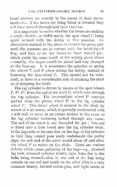
LAG CYLINDER-ESCAPE MOTION 85
heald section) are exactly in the centre of their move-
ment
—
i.e., if the boxes are being hfted or lowered they
will have moved through half their traverse.
It is important to notice whether the boxes are making
a single, double, or treble move, the spur wheel C being
again secured with the dobby in this position. Analternative method to the above is to turn the going part
until the jammers are in contact with the knocking-off
frog, and then to set the. boxes to have moved Jin.,
which yields the same result as the setting given above
—namely, the boxes would be about half-way changed
at the beat-up. It is sometimes the practice to spring
the wheels E and F when setting the dobby, instead of
loosening the spur-wheel C. This should not be toler-
ated, as there is a considerable risk of straining the shaft
or of stripping the teeth.
The lag cylinder is driven by means of the spur-wheels
P, Pi, P-, from the end of the shaft O, which runs through
the top cylinder. The intermediate wheel Pi conveys
motion from the pinion wheel P^ to the lag cylinder
wheel P. This latter wheel is secured to the shaft bymeans of a set-screw, which is specially constructed with
a soft end, to serve as an escape motion in the event of
the lag cylinder becoming locked through any cause.
The end of the screw is not threaded for Jin.; this end
is fitted into a hole bored into the lag cylinder shaft.
If the lags ride or become fast on the lugs of the cylinder
so that they cannot pass freely underneath the pulley
slips, the soft end of the screw would shear off and allow
the wheel P to rotate on the shaft. There are various
defects which cause gathering of the lags
—
e.g., strained
lag rods, strained cylinder blades, tight links due to the
links being crossed—that is, one end of the link being
outside on one rod and inside on the other (this is a very
common defect), twisted cotter-pins, and tight bowls or
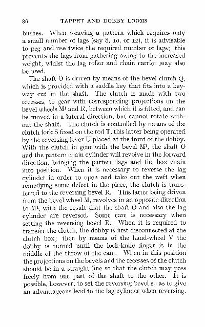
86 TAPPET AND DOBBY LOOMS
bushes. When weaving a pattern which requires only
a small number of lags (say 8, lo, or 12), it is advisable
to peg and use twice the required number of lags; this
prevents the lags from gathering owing to the increased
weight, whilst the lag roller and chain carrier may also
be used.
The shaft O is driven by means of the bevel clutch Q,
which is provided with a saddle key that fits into a key-
way cut in the shaft. The clutch is made with two
recesses, to gear with corresponding projections on the
bevel wheels M^ and R, between which it is fitted, and can
be moved in a lateral direction, but cannot rotate with-
out the shaft. The clutch is controlled by means of the
clutch fork S fixed on the rod T, this latter being operated
by the reversing lever U placed at the front of the dobby.
With the clutch in gear with the bevel M^, the shaft Oand the pattern chain cylinder will revolve in the forward
direction, bringing the pattern lags and the box chain
into position. When it is necessary to reverse the lag
cylinder in order to open and take out the weft when
remedying some defect in the piece, the clutch is trans-
ferred to the reversing bevel R. This latter being driven
from the bevel wheel M, revolves in an opposite direction
to M^ with the result that the shaft O and also the lag
cylinder are reversed. Some care is necessary when
setting the reversing bevel R. When it is required to
transfer the clutch, the dobby is first disconnected at the
clutch box; then by means of the hand-wheel V the
dobby is turned until the lock-knife finger is in the
middle of the throw of the cam. When in this position
the projections on the bevels and the recesses of the clutch
should be in a straight line so that the clutch may pass
freely from one part of the shaft to the other. It is
possible, however, to set the reversing bevel so as to give
an advantageous lead to the lag cylinder when reversing.
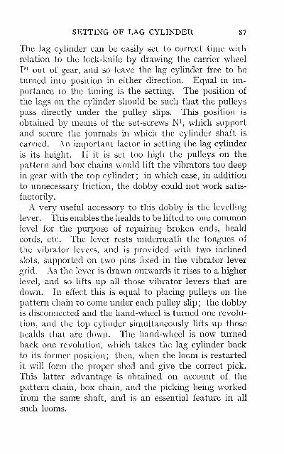
SETTING OF LAG CYLINDER 87
The lag cylinder can be easily set to correct time with
relation to the lock-knife by drawing the carrier wheelPi out of gear, and so leave the lag cylinder free to be
turned into position in either direction. Equal in im-
portance to the timing is the setting. The position of
the lags on the cylinder should be such that the pulleys
pass directly under the pulley slips. This position is
obtained by means of the set-screws N^, which support
and secure the journals in which the cylinder shaft is
carried. An important factor in setting the lag cylinder
is its height. If it is set too high the pulleys on the
pattern and box chains would lift the vibrators too deep
in gear with the top cylinder; in which case, in addition
to unnecessary friction, the dobby could not work satis-
factorily.
A very useful accessory to this dobby is the levelling
lever. This enables the healds to be lifted to one commonlevel for the purpose of repairing broken ends, heald
cords, etc. The lever rests underneath the tongues of
the vibrator levers, and is provided with two inclined
slots, supported on two pins fixed in the vibrator lever
grid. As the lever is drawn outwards it rises to a higher
level, and so lifts up all those vibrator levers that are
down. In effect this is equal to placing pulleys on the
pattern chain to come under each pulley slip ; the dobbyis disconnected and the hand-wheel is turned one revolu-
tion, and the top cylinder simultaneously lifts up those
healds that are down. The hand-wheel is now turned
back one revolution, which takes the lag cylinder back
to its former position; then, when the loom is restarted
it will form the proper shed and give the correct pick.
This latter advantage is obtained on account of the
pattern chain, box chain, and the picking being workedfrom the sam^ shaft, and is an essential feature in all
such looms.
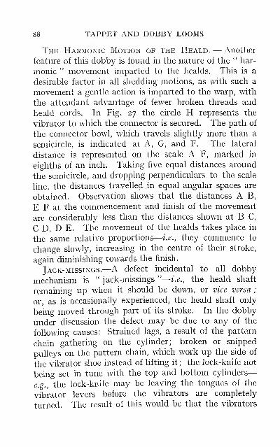
88 TAPPET AND DOBBY LOOMS
The Harmonic Motion of the Heald. — Another
feature of this dobby is found in the nature of the " har-
monic " movement imparted to the healds. This is a
desirable factor in all shedding motions, as with such a
movement a gentle action is imparted to the warp, with
the attendant advantage of fewer broken threads and
heald cords. In Fig. 27 the circle H represents the
vibrator to which the connector is secured. The path of
the connector bowl, which travels slightly more than a
semicircle, is indicated at A, G, and F. The lateral
distance is represented on the scale A F, marked in
eighths of an inch. Taking five equal distances around
the semicircle, and dropping perpendiculars to the scale
hne, the distances travelled. in equal angular spaces are
obtained. Observation shows that the distances A B,
E F at the commencement and finish of the movement
are considerably less than the distances shown at B C,
C D, D E. The movement of the healds takes place in
the same relative proportions
—
i.e., they commence to
change slowly, increasing in the centre of their stroke,
again diminishing towards the finish.
Jack-missings.—A defect incidental to aU dobby
mechanism is'' jack-missings "
—
i.e., the heald shaft
remaining up when it should be down, or vice versa ;
or, as is occasionally experienced, the heald shaft only
being moved through part of its stroke. In the dobby
under discussion the defect may be due to any of the
following causes: Strained lags, a result of the pattern
chain gathering on the cylinder; broken or snipped
pulleys on the pattern chain, which work up the side of
the vibrator shoe instead of lifting it ; the lock-knife not
being set in tune with the top and bottom cylinders
—
e.g., the lock-knife may be leaving the tongues of the
vibrator levers before the vibrators are completely
turned. The result of this would be that the vibrators
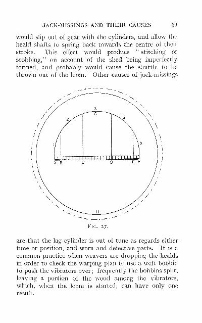
JACK-MISSINGS AND THEIR CAUSES 89
would slip out of gear with the cylinders, and allow the
heald shafts to spring back towards the centre of their
stroke. This effect would produce " stitching or
scobbing," on account of the shed being imperfectly
formed, and probably would cause the shuttle to be
thrown out of the loom. Other causes of jack-missings
Fig. 27.
are that the lag cylinder is out of tune as regards either
time or position, and worn and defective parts. It is a
common practice when weavers are dropping the healds
in order to check the warping plan to use a weft bobbin
to push the vibrators over; frequently the bobbins split,
leaving a portion of the wood among the vibrators,
which, when the loom is started, can have only one
result.
90 TAPPET AND DOBBY LOOMS
The missing of jacks may be occurring on any or all
of the healds; this is soon in evidence in the wovenfabric, and denotes that the mechanism generally needs
overhauling. If, however, the defect is only produced
by one heald shaft, it may either at regular intervals,
or of one repeat of the pattern chain, or at irregular
intervals in the piece. The best method of dealing with
such defects is to trace out the floating thread of warp
and follow it to the healds to ascertain on which heald
shaft it is drawn. The parts controlling that particular
shaft may then be carefully examined and overhauled.
.
Lever Dobby.—It may be safely asserted that
dobbies built on the lever principle are far more numerous
than wheel dobbies. This is easily accounted for by the
fact that there are so many different makers producing
their own specialities of lever dobbies. A very simple
style of lever dobby, and one extensively used, is knownas the " double-lift " with negative action. Such a
dobby is constructed with two lifting knives, for operat-
ing the draw hooks which control the jacks and impart
motion to the heald shaft. This mechanism actuates
the heald shaft in one direction only
—
i.e., lifts the shafts;
a reversing motion being necessary to draw back the
shaft to its former position. The style of shed produced
is the open-shed, the heald shafts being kept elevated for
the requisite number of picks. The negative action of
such dobbies renders them unsuitable for weaving heavy
goods, as with such cloths considerably more power must
be applied to the heald shafts, in order to keep the warp
on tlie race and prevent it from being lifted by the ex-
cessive tension applied when shedding. The result of this
would be that the shuttle would be impeded in its course
if not thrown off the race. To enable such dobbies to be
employed for heavy goods, a very powerful reversing
motion is necessary. Occasionally the number of springs
DEFECTS OF NEGATIVE DOBBIES 91
is doubled
—
i.e., two or more springs are attached to the
heald shafts. Such a conventional method can only
result in more power being expended in the formation of
the shed. The worst feature of negative shedding is
revealed when weaving cloths composed of uneven sheds
—e.g., backed or double cloths; some sheds have few
shafts lifted, while the succeeding pick may have con-
siderably more. The outcome of this is that the springs
oppose the working of the loom when the shed is being
formed, and work with the loom when the shed is closing,
yielding very unsteady running. Another disadvantage
of such dobbies is the absence of any provision for re-
versing the dobby, also the take-up motion, when the
weaver has occasion to pick back for any defect. The
lag cylinder in such dobbies is usually operated from the
bottom lifting knife during its forward stroke, by means
of a catch actuating the ratchet wheel. This latter is
made with six or eight teeth, according to the form of the
lag cylinder, and is fitted to the end of the cylinder shaft.
The pattern lags in such a form of dobby are constructed
with a double row of holes, the first row being pegged to
indicate for the odd picks of the weave, the back row
being pegged for the even picks. This arrangement is
undesirable because of the small space available in which
the tumblers and needles have to work. A further dis-
advantage is met with in this type of dobby in the short
dwell imparted to the healds to allow for the passage of
the shuttle. The lifting knives are invariably operated
from the low shaft of the loom by means of a crank and
connecting rod, so that only such time as it takes the
crank to pass the top and bottom centres is allowed for
the passage of the shuttle.
The following is a summary of the various causes of
" jack-missings " in this type of dobby: [a) It is essential
when connecting the lags to fasten them together so that
92 TAPPET AND DOBBY LOOMS
each lag is equidistant apart, otherwise they are hable
to ride on the cyhnder and not pass freely under the
tumblers ; or if they do pass forward, the edge of the lag
will lift up all or part of the tumblers and give a wrongshed. Rings should be used for connecting the lags
together, and not string, (b) Needles sticking. To avoid
this, keep the parts free from grease, and use a good
quality of oil. (c) If wood pegs are used they occasion-
ally become bruised, resulting in the top of the peg being
broader, and so tending to lift up the adjoining tumbler.
(d) Beware of broken or short pegs, also of pegs dropping
out. (e) Draw hooks slipping off the knife when midwayin their stroke. (/) The lag cylinder not in correct
position with the tumblers. (g) The most important
feature in the type of dobby illustrated in Fig. 28 is the
timing of the lag cylinder in relation to the lifting knives.
The cylinder should be timed to bring the next lag into
position just before the lifting knives reach the extremity
of their stroke. This would then allow any of the hooks
to drop on to the knives where a peg had been inserted
in the pattern chain, or allow such hooks to be lifted off
the knives, where a blank follows a peg, so that the top
sneck of the draw hook may come in contact with the
retaining bars. It is also of the utmost importance that
the stroke given to the knives and lowering bars, as well
as the position of the retaining bars, should be such as
will allow the hooks to be low^ered or lifted quite freely,
and be quite clear at the time when they are changing
positions.
Hattersley Double-action Open-shed Dobby.—A more modern form of this type of dobby is illustrated
in front elevation, in Fig. 28. This dobby is constructed
on the double-action principle, yielding a positive motion
to the healds, producing an open shed. The healds are
connected from the top to the upper arm of the jack A,
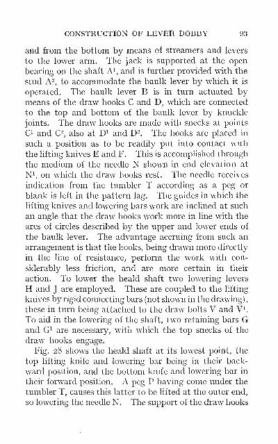
CONSTRUCTION OF LEVER DOBBY 93
and from the bottom by means of streamers and levers
to the lower arm. The jack is supported at the open
bearing on the shaft A^, and is further provided with the
stud A2, to accommodate the baulk lever by which it is
operated. The baulk lever B is in turn actuated bymeans of the draw hooks C and D, which are connected
to the top and bottom of the baulk lever by knuckle
joints. The draw hooks are made with snecks at points
Ci and C", also at D^ and D^. The hooks are placed in
such a position as to be readily put into contact with
the lifting knives E and F. This is accomplished through
the medium of the needle N shown in end elevation at
N^ on which the draw hooks rest. The needle receives
indication from the tumbler T according as a peg or
blank is left in the pattern lag. The guides in which the
lifting knives and lowering bars work are inclined at such
an angle that the draw hooks work more in line with the
arcs of circles described by the upper and lower ends of
the baulk lever. The advantage accruing from such an
arrangement is that the hooks, being drawn more directly
in the line of resistance, perform the work with con-
siderably less friction, and are more certain in their
action. To lower the heald shaft two lowering levers
H and J are employed. These are coupled to the lifting
knives by rigid connecting bars (not shown in the drawing)
,
these in turn being attached to the draw bolts V and V^.
To aid in the lowering of the shaft, two retaining bars Gand G^ are necessary, with which the top snecks of the
draw hooks engage.
Fig. 28 shows the heald shaft at its lowest point, the
top lifting knife and lowering bar being in their back-
ward position, and the bottom knife and lowering bar in
their forward position. A peg P having come under the
tumbler T, causes this latter to be lifted at the outer end,
so lowering the needle N. The support of the draw hooks
94 TAPPET AND DOBBY LOOMS
being withdrawn, they drop immediately they are re-
leased at the retaining catch. The top hook falls and
rests on the knife E ; the bottom hook falls with the sneck
Di directly behind the bottom knife F. At the next
movement of the lifting knives the bottom draw hook
win be drawn back, and with it the baulk lever B, which
is prevented from working forward at the top by reason
of the fixed bar K. This allows the jack to be pulled
over on its fulcrum and so lift the shaft. If the heald is
required to be lifted for more than one pick in succession,
another peg would have to be placed in the next lag,
and so permit the top hook to drop on to the top
knife E, which has now moved to its forward position.
The action which is now taking place is simply that
the baulk lever is turning on its fulcrum A^, keeping
the heald shaft elevated so long as a succession of
pegs are placed in the pattern lags to keep up the
tumbler T.
Assuming that the heald requires to be lifted for one
pick only, then, as the knives and lowering bars approach
the end of their stroke, another lag is brought into posi-
tion, and as a result of there being no peg to support the
tumbler it falls by reason of its own weight, lifting up the
needle and the draw hook at the same time. The sneck
C^ of the top draw hook now comes into contact with the
retaining bar G, preventing it from moving backward,
whilst the bottom lowering bar J, which is now returning
to its forward position, presses against the lower end of
the baulk lever, and at the same time carries the jack and
heald shaft to their bottom position. With a succession
of blanks in the pattern lags the snecks O and D^ of the
top and bottom draw hooks keep in contact with the re-
taining bars G and G^. This prevents the heald shaft
from being lifted from the level of the bottom shed line
by the tension of the warp threads. Motion is imparted
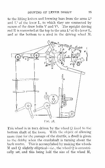
DRIVING OF LEVER DOBBY 95
to the lifting knives and lowering bars from the arms L^
and U of the lever L, to which they are connected by
means of the draw bolts V and V^. The upright driving
rod R is connected at the top to the arm L^ of the lever L,
and at the bottom to a stud in the driving wheel M.
This wheel is in turn driven by the wheel Q fixed to the
bottom shaft of the loom. With the object of allowing
more time for the passage of the shuttle, a dwell is given
to the dobby when the crankshaft is turning about the
back centre. This is accomplished by making the wheels
M and Q slightly elliptical
—
i.e., the wheel Q is eccentri-
cally set, and this being half the size of the wheel M,
96 TAPPET AND DOBBY LOOMS
necessitates this being elliptical in shape, as shown in endelevation.
Harmonic motion in this and similar types of dobbies
is obtained from the nature of the mechanism employedfor operating the dobby. This is usually performed bycoupling the driving rod R to a crank fixed on the end of
the low shaft, or as shown in Fig. 28. An advantage is
claimed for this type of dobby owing to the reciprocating
motion of the lifting knives, as the dobby mechanismthus only runs at half the speed of the loom, and is there-
fore steadier in action and attended with less friction.
Provision is made in this type of loom for timing the
shedding motion to the beat-up by introducing two stud
holes I and 2 in the wheel M. The stud can be fixed into
either hole as required. One would give the earliest
position for shedding, the other the latest, no intermedi-
ate position being available. To reverse the pattern and
box chains, which in this loom are worked from the samecylinder, the rod S is employed. This rod is attached to
the brackets S^ and S- fitted to the shafts W and Xrespectively. The shaft W is suitably connected to the
fork lever which indicates the side of the loom from which
the pick will take place. The shaft X is connected to the
reversing clutch on the take-up shaft, from which the lag
cylinder is driven. When the reversing lever is trans-
ferred to the middle position, the picking is rendered
inoperative, but the lag cylinder and take-up motion con-
tinue to move forward as the loom is turned over. Toreverse the direction of the lag cylinder and take-up
motion, the rod is transferred to the position marked S^.
To take out the picks the loom has to be turned over for
each pick withdrawn. The experienced weaver can take
out the picks as quickly in this loom as is possible in
looms where the dobby mechanism is operated by handfor this purpose.
TYPES OF DOBBIES 97
The two styles of dobbies already considered show in
detail the principles underlying the construction of modern
dobby mechanism. It is not intended to give any further
consideration to these types, since most other dobbies
can be compared in detail with those described, and con-
clusions drawn as to the merits of one dobby or system
over another.
Centre Closed-shed Dobby.—This type of dobbyvaries from the two former in the style of shed produced.
It is essentially a lever dobby, but is constructed to give
a centre closed shed. The healds are all brought to one
common level after the insertion of each pick. To form
the shed some healds are lifted, and the remainder drawndown to form the top and bottom shed lines respectively.
When a heald shaft is to be lifted for more than one pick
in succession, it must return to the centre to be again
lifted for the next pick, and similarly for the shafts that
are to be down. This style of shedding mechanism im-
parts considerably more movement to the warp threads
than is the case in open-shed dobbies; this factor is
responsible for the increased driving power required for
such dobbies. The loom cannot be run at so high a rate
of speed as is possible with the open-shed dobby, for the
motion given to the healds results in more wear and
friction between the parts. These are no doubt the chief
reasons why this type of dobby is not more extensively
employed, as this system of shedding does possess certain
advantages not found in open shedding.
Cross Border Dobby.—This is an ordinary type of
dobby to which certain mechanism has been added as an
accessory for obtaining a special result. Such a dobbyfacilitates the production of bordered fabrics—namely,
towels, shawls, table-covers, etc. In some dobbies this
is accomphshed by employing two pattern chain cylinders,
one cylinder being used for the ground of the fabric, or
G
98 TAPPET AND DOBBY LOOMS
the edges and centre, the other cyhnder being used for
the borders (weft way) of the fabric. Either of these two
cyhnders may be put into operation by receiving indica-
tion from a third cyhnder, by which they are controUed,
according to the number of repeats required of each to
form the edge, border, or centre of the fabric. Such
mechanism is entirely automatic in its action. Another
method is to employ one lag cylinder only, which is
driven in such a way as to pass two pattern lags forward
at each pick. With this mechanism the respective
designs for the centre and borders of the fabric would be
pegged as follows:—The design for the centre and edges,
which are invariably the same pattern, would be pegged
on the odd-numbered lags, the design for the border
on the even-numbered lags. When the requisite num-ber of repeats for the edge or border have been com-
pleted, the lags are turned one lag backward or forward
to bring the alternate pattern lags into operation. Withthis mechanism the changes are dependent upon the
weaver. The former is the most common principle, and
is chiefly employed on lever dobbies for weaving the
class of fabrics named.
Defective Shedding.—That there are defects in
cloth caused by imperfect shedding, other than those due
to " jack -missings," is well known. These may be
summarised as follows:
—
Reediness in Cloth.—There are certain fabrics which
require to have all traces of reed marks entirely obliter-
ated, the object being to give to the fabric an appearance
of fullness and density, or what is usually spoken of as
" cover." As examples of this, plain calico, also union
cloths in which the warp is cotton and the weft woollen,
worsted, or angola, may be cited. Usually the latter
class of cloth is woven in plain weave with such a numberof picks per inch and the weft of such a count that the
COVER ON CLOTH 99
cotton warp will be completely hidden by the weft.
These results are best obtained by troughing the shed,
though this practice is to deviate somewhat from the
formation of a perfect shed. A perfectly-formed shed
is understood to be one in which the top and bottom shed
lines of warp are equal distances from the warp line.
The warp line is the position taken up by a tensioned
cord when passed over the back roller and the piece
beam. It is evident that when the top and bottom shed
lines are drawn equal distances from the warp line the
tension on each will be the same. Under such condi-
tions the threads will work in groups as they are passed
through the reed, showing the position of the reed marksquite distinctly, and giving to the piece a raw and lean
appearance. Troughing the shed consists in adjusting
the position of the back roller and piece beam, chiefly byraising the back roller, so that the bottom shed line of
warp is depressed more below the warp line than the top
shed line is raised above it. The result is that greater
tension is applied to the threads when at the bottomshed line than when forming the top shed, as when in
this position they are practically free from tension.
When troughing the shed is resorted to for the purpose
of obtaining cover on a cloth, the alternate tightening
and slackening of the threads, as they form part of the
bottom and top shed lines, imparts to them a recipro-
cating motion. This movement of the warp threads, as
they are intersected with the weft, will naturally cause
them to work towards the point of least resistance
—
i.e.,
to the centre of the long weft float caused by the reed
wire. In addition to the threads being more equally
distributed, the shrinkage of the warp and the weft will
be more uniform, giving better cover to the fabric.
The operation of troughing the shed has also a decided
effect on the twill of a cloth. Observations on the
100 TAPPET AND DOBBY LOOMS
results of experiments made in this direction, also from
practical experience, prove that the twill is more pro-
nounced in a cloth woven with a troughed shed. In a
cloth woven without the shed being troughed, the weave
being a 2-and-2 twill, the warp black cotton dented 12
reed 4's, and the weft white worsted, every fourth pick
had the appearance of intersecting i-and-i instead of
2-and-2. This was entirely due to the reed splitting the
first and fourth threads, and thus the continuity of the
twill appeared broken. This defect entirely disap-
peared after the shed was troughed. Another instance
occurred in which the twill was more pronounced in the
first part of the piece than in the latter part. The piece
had been woven in a loom in which the back roller
bracket was provided with two bearings, a higher and a
lower, into either of which the back roller could be
placed according to the wetting requirements. It was
proved that the first part of the piece had been woven
with the roller in the top bearing, giving a troughed shed
;
for weighting the warp the roller was then transferred
into the low bearing, which had the effect of tightening
the top shed line. The piece being finished " clean cut,''
the diference in the twill of the two portions was revealed
in a marked degree.
Uneven Shedding.—The healds should be hung quite
level and adjusted for the stroke according to their
position in the gear, otherwise this may be the cause of
certain common defects. One of these is for the piece
to contain cracks or lines running inwards from the
selvage of the piece and diminishing towards the centre.
Such a defect is most noticeable in fabrics made from
yarns of contrasting colours in warp and weft. This
kind of defect is brought about by reason of one or more
of the heald shafts not working level
—
i.e., one side of the
heald being higher or lower than the other side. The
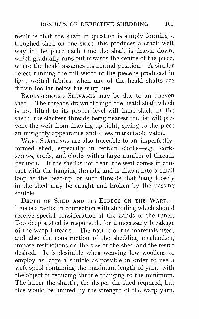
RESULTS OF DEFECTIVE SHEDDING 101
result is that the shaft in question is simply forming a
troughed shed on one side; this produces a crack weft
way in the piece each time the shaft is drawn down,
which gradually runs out towards the centre of the piece,
where the heald assumes its normal position. A similar
defect running the full width of the piece is produced in
light wefted fabrics, when any of the heald shafts are
drawn too far below the warp line.
Badly-formed Selvages may be due to an uneven
shed. The threads drawn through the heald shaft which
is not lifted to its proper level will hang slack in the
shed ; the slackest threads being nearest the list will pre-
vent the weft from drawing up tight, giving to the piece
an unsightly appearance and a less marketable value.
Weft Staplings are also traceable to an imperfectly-
formed shed, especially in certain cloths
—
e.g., cork-
screws, cords, and cloths with a large number of threads
per inch. If the shed is not clear, the weft comes in con-
tact with the hanging threads, and is drawn into a small
loop at the beat-up, or such threads that hang loosely
in the shed may be caught and broken by the passing
shuttle.
Depth of Shed and its Effect on the Warp.—This is a factor in connection with shedding which should
receive special consideration at the hands of the tuner.
Too deep a shed is responsible for unnecessary breakage
of the warp threads. The nature of the materials used,
and also the construction of the shedding mechanism,
impose restrictions on the size of the shed and the result
desired. It is desirable when weaving low woollens to
employ as large a shuttle as possible in order to use a
weft spool containing the maximum length of yarn, with
the object of reducing shuttle-changing to the minimum.The larger the shuttle, the deeper the shed required, but
this would be limited by the strength of the warp yarn.
102 TAPPET AND DOBBY LOOMS
If the strain imposed is in excess of the elasticity of the
yarn, more time would be lost in repairing the brokenthreads than would be gained by increasing the dimen-
sions of the spool and the shuttle. The mechanism of a
dobby imposes limitations on the depth of shed that
could be obtained. Dobbies containing 24 and 36 jacks
are largely employed in fancy woollen and worsted
weaving. Between the first and last heald shafts there
will be a distance of from 10 to I5in., so that the maximumdepth of shed and size of shuttle will be determined bythe possible stroke of the back heald shaft.
Perfect Slope of Shed.—To obtain a perfectly
sloping shed it is evident that the further the healds are
from the fell of the cloth their stroke must be increased
in proportion to their position. The threads which are
drawn on the back shafts will be subjected to consider-
ably more tension, as they are lifted and depressed moreout of the warp line than those drawn on the front shafts.
The material might sustain the tension applied by the
front shafts, but would be altogether inadequate for the
tension applied by the back shafts. It is on this account
occasionally advisable to resort to drafting the gear whenpossible—taking, for example, a warp backed, or a
double, cloth, in which one set of the warp threads is
made from a different material, as worsted for the face
and cotton for the back of the fabric, or they may be
made of the same materials but different qualities. Theset of threads least capable of resisting the tension
should be drawn into the front healds, if the structure
of . the design renders this possible. The principle of
drafting may also be employed for the purpose of assist-
ing to clear the shed. For instance, take a fabric madefrom coarse fibrous yarn with which it is difficult to clear
the shed. The weave is the 4-and-4 twill, straight draft
on 8 shafts. Clearing the shed may be facilitated by
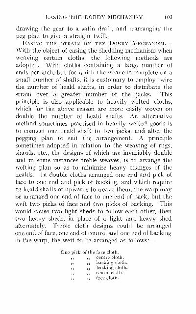
EASING THE DOBBY MECHANISM 103
drawing the gear to a satin draft, and rearranging the
peg plan to give a straight twill.
Easing the Strain on the Dobby Mechanism.—With the object of easing the shedding mechanism whenweaving certain cloths, the following methods are
adopted. With cloths containing a large number of
ends per inch, but for which the weave is complete on a
small number of shafts, it is customary to employ twice
the number of heald shafts, in order to distribute the
strain over a greater number of the jacks. This
principle is also applicable to heavily wefted cloths,
which for the above reason are more easily woven on
double the number of heald shafts. An alternative
method sometimes practised in heavily wefted goods is
to connect one heald shaft to two jacks, and alter the
pegging plan to suit the arrangement. A principle
sometimes adopted in relation to the weaving of rugs,
shawls, etc., the designs of which are invariably double
and in some instances treble weaves, is to arrange the
wefting plan so as to minimise heavy changes of the
healds. In double cloths arranged one end and pick of
face to one end and pick of backing, and which require
12 heald shafts or upwards to weave them, the warp maybe arranged one end of face to one end of back, but the
weft two picks of face and two picks of backing. This
would cause two light sheds to follow each other, then
two heavy sheds, in place of a light and heavy shed
alternately. Treble cloth designs could be arranged
one end of face, one end of centre, and one end of backing
in the warp, the weft to be arranged as follows:
—
One pick of ihe face cloth.
,, ,, centre cloth.
,, ,, backing clolh.
,, ,, backing cloth.
,, ,, centre cloth.
,, ,, face cloth.

104 TAPPET AND DOBBY LOOMS
This would bring two light sheds for the face together,
preceded and followed by a centre cloth shed, whichwould require all the face shafts lifted and all the back-
ing shafts down, except those used for stitching. Thechanges to and from the heavy backing sheds are thus
introduced with less strain on the shedding mechanism.
CHAPTER V
PICKING MECHANISM
This motion demands considerable time and attention
from the tuner. Not only does the motion require
careful attention, but in the hands of the competent
tuner, much more the incompetent, it is the chief source
of expense due to repairs and renewals of pickers,
shuttles, check and other strappings. In short, the pick-
ing motion is capable of increasing or decreasing to a
great extent the utility and earning capacity of a loom.
This will be better understood by taking into account the
following factors which are common to all picking
mechanism :
—
{a) The action of all picking motions is practically a
negative one. The force of the pick is expended on the
shuttle, thus driving it out of the box. The shuttle is
then left to travel across the race through the open shed
under no control except the contact it makes with the
race and the reed.
(b) The movement of the shuttle race renders it a
matter of great difficulty to prevent the shuttle diverg-
ing from a straight course. The pick is timed to take
place while the going part is receding towards the back
centre. The shuttle will therefore have travelled somedistance across the race when the back centre is reached,
the race remaining stationary at this point for a short
period. The race then commences to move in a forward
direction, during such time as the shuttle travels the
remaining distance and enters the shuttle-box.
105
106 TAPPET AND DOBBY LOOMS
(c) The speed at which the shuttle must travel across
the race must also be noted. This is calculated to
average about 40ft. per second in quick-running loomsof various widths
—
e.g., a loom running at the rate of
100 picks per minute has a reed space of 78in., and the
length of the shuttle-box is i8in. The shuttle travels
a distance equal to 8ft. at each pick, and assuming that
one-third of the revolution of the crank is occupied for
the passage of the shuttle, the shuttle will travel 100 x 8ft.
in 20 seconds, or an average of 40ft. per second.
(d) Checking the shuttle travelling at the above speed
in a space of from 3 to 5in. is an operation attended with
possibilities that may prove detrimental to the desired
result.
(e) The tendency for the shuttle to be drawn off the
race, on account of the weft passing through the eyelets
which are placed at one end of the shuttle, is largely
influenced by the amount of tension put on the weft,
which varies with the nature of the material used. Thelighter the shuttle the greater the possibility of it being
drawn off the race.
(/) Any variation in the weight of the shuttle used
affects the pick. A full or empty spool, and also any
slight discrepancy in the sizes of different shuttles, have
their effect.
{g) Obstructions in the shed may occur at any time, due
to broken threads or heald cords, and so cause trouble.
From the above it will be obvious that the picking
mechanism may become the source of considerable
trouble. In order to make this motion as accurate in its
action as possible, the following parts have received
special attention—viz., the shuttle, the race, and the
nature of the pick to be given to the shuttle, for successful
results can only be obtained by these parts being kept
in good working condition.
SHUTTLE CONSTRUCTION 107
Shuttles.—These may be considered as belonging to
one of two classes—wheel shuttles and sledge shuttles.
The former are not used on modern tappet and dobby
looms; they were chiefly employed in the top swing slow
loom, a type now rarely made. Such shuttles were ex-
ceptionally heavy, being fitted with steel side plates.
One feature of this type of shuttle was that the wheels
could be fixed at such an angle as to guide the shuttle
towards the reed, which reduced to a very appreciable
degree the liability of the shuttle to run off the race.
The construction of the sledge shuttle is designed to
obtain exactly the same result. To effect this the back
of the shuttle is made straight for a greater length than
at the front. By this means more surface contact with
the shuttle-box back and the reed is obtained. The bevel
of the shuttle must coincide with the angle formed by the
race and the reed. The shuttle tip is sometimes set
slightly to the front and a little below the centre of the
shuttle. The object of this arrangement is to enable the
shuttle to force its way under any obstruction in the shed,
and it is therefore not so easily thrown out. A further
advantage obtained from a shuttle made in this way is
that a slight bias is given to that side of the shuttle
running against the reed. The weight of the shuttle
should be such as will best suit the nature of the weft with
reference to the drag, whilst the size should be sufficiently
large to accommodate the weft cops it is intended to use.
Shuttles should be made from special wood, and the
tuner will do well to avoid the cheaper makes of shuttles,
as these quickly wear up rough, and are liable to split
with the momentum and impact when entering the box.
The shuttle and the weft cop may be responsible for
the following defects: If the shuttles in a set vary in size
and weight the loom will be constantly knocking off,
or the shuttle thrown out of the loom; as a result it is
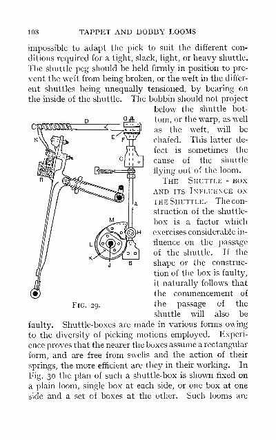
108 TAPPET AND DOBBY LOOMS
impossible to adapt the pick to suit the different con-
ditions required for a tight, slack, light, or heavy shuttle.
The shuttle peg should be held firmly in position to pre-
vent the weft from being broken, or the weft in the differ-
ent shuttles being unequally tensioned, by bearing on
the inside of the shuttle. The bobbin should not project
below the shuttle bot-
tom, or the warp, as well
as the weft, will be
chafed. This latter de-
fect is sometimes the
cause of the shuttle
flying out of the loom.
The Shuttle - boxAND ITS Influence on
THE Shuttle.—The con-
struction of the shuttle-
box is a factor which
exercises considerable in-
fluence on the passage
of the shuttle. If the
shape or the construc-
tion of the box is faulty,
it naturally follows that
the commencement of
the passage of the
shuttle will also be
faulty. Shuttle-boxes are made in various forms owing
to the diversity of picking motions employed. Experi-
ence proves that the nearer the boxes assume a rectangular
form, and are free from swells and the action of their
springs, the more efficient are they in their working. In
Fig. 30 the plan of such a shuttle-box is shown fixed on
a plain loom, single box at each side, or one box at one
side and a set of boxes at the other. Such looms are
Fig. 29.
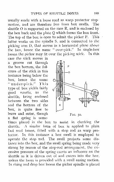
TYPES OF SHUTTLE BOXES 109
usually made with a loose reed as warp protector stop-
motion, and are therefore free from box swells. The
shuttle O is supported on the race R, and is enclosed by
the box back and the plate Q which forms the box front.
The top of the box is open to admit the picker P. This
latter works on the spindle S, and is connected to the
picking arm D, that moves in a horizontal plane above
the box, hence the name " over-pick." In single-box
looms the picker may fit over the picking stick. In this
case the stick moves in
a groove cut through
the box bottom, the ful-
crum of the stick in this
instance being below the
box, hence the name" under-pick." Thistype of box yields fairly
good results, as the
shuttle, being enclosed
between the two sides
and the bottom of the
box, is quite free to
leave and enter, though
a fiat spring is some-
times placed in the box
shuttle. A similar form
Fig.
to assist in checking the
of box is applied to plain
fast reed looms, fitted with a stop rod as warp pro-
tector. In this instance a box swell is employed to
operate the stop rod. The swell projects some dis-
tance into the box, and the swell spring being made very
strong by reason of the stop-rod arrangement, the ex-
cessive pressure of the spring exerts an influence on the
shuttle as it is driven out of and enters into the box,
unless the loom is provided with a swell easing motion.
In rising and drop box looms the picker spindle is placed
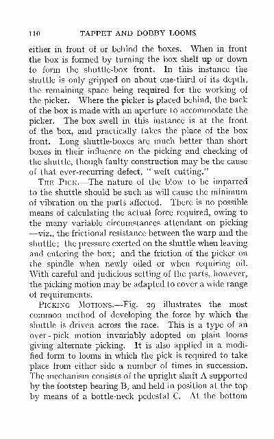
110 TAPPET AND DOBBY LOOMS
either in front of or behind the boxes. When in front
the box is formed by turning the box shelf up or downto form the shuttle-box front. In this instance the
shuttle is only gripped on about one-third of its depth,
the remaining space being required for the working of
the picker. Where the picker is placed behind, the back
of the box is made with an aperture to accommodate the
picker. The box swell in this instance is at the front
of the box, and practically takes the place of the box
front. Long shuttle-boxes are much better than short
boxes in their influence on the picking and checking of
the shuttle, though faulty construction may be the cause
of that ever-recurring defect, " weft cutting."
The Pick.—The nature of the blow to be imparted
to the shuttle should be such as will cause the minimumof vibration on the parts affected. There is no possible
means of calculating the actual force required, owing to
the many variable circumstances attendant on picking
—viz., the frictional resistance between the warp and the
shuttle ; the pressure exerted on the shuttle when leaving
and entering the box; and the friction of the picker on
the spindle when newly oiled or when requiring oil.
With careful and judicious setting of the parts, however,
the picking motion may be adapted to cover a wide range
of requirements.
Picking Motions.—Fig. 29 illustrates the most
common method of developing the force by which the
shuttle is driven across the race. This is a type of an
over - pick motion invariably adopted on plain looms
giving alternate picking. It is also applied in a modi-
fied form to looms in which the pick is required to take
place from either side a number of times in succession.
The mechanism consists of the upright shaft A supported
by the footstep bearing B, and held in position at the top
by means of a bottle-neck pedestal C. At the bottom
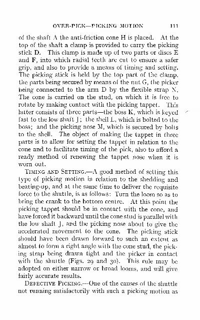
OVER-PICK—PICKING MOTION 111
of the shaft A the anti-friction cone H is placed. At the
top of the shaft a clamp is provided to carry the picking
stick D. This clamp is made up of two parts or discs Eand F, into which radial teeth are cut to ensure a safer
grip, and also to provide a means of timing and setting.
The picking stick is held by the top part of the clamp,
the parts being secured by means of the nut G, the picker
being connected to the arm D by the flexible strap N.
The cone is carried on the stud, on which it is free to
rotate by making contact with the picking tappet. This
latter consists of three parts—the boss K, which is keyedfast to the low shaft J ; the shell L, which is bolted to the
boss; and the picking nose M, which is secured by bolts
to the shell. The object of making the tappet in three
parts is to aUow for setting the tappet in relation to the
cone and to facilitate timing of the pick, also to afford a
ready method of renewing the tappet nose when it is
worn out.
Timing and Setting.—A good method of setting this
type of picking motion in relation to the shedding andbeating-up, and at the same time to deliver the requisite
force to the shuttle, is as follows: Turn the loom so as to
bring the crank to the bottom centre. At this point the
picking tappet should be in contact with the cone, andhave forced it backward until the cone stud is parallel with
the low shaft J, and the picking nose about to give the
accelerated movement to the cone. The picking stick
should have been drawn forward to such an extent as
almost to form a right angle with the cone stud, the pick-
ing strap being drawn tight and the picker in contact
with the shuttle (Figs. 29 and 30). This rule may be
adopted on either narrow or broad looms, and will give
fairly accurate results.
Defective Picking.—One of the causes of the shuttle
not running satisfactorily with such a picking motion as
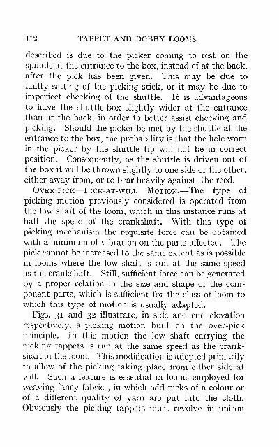
112 TAPPET AND DOBBY LOOMS
described is due to the picker coming to rest on the
spindle at the entrance to the box, instead of at the back,
after the pick has been given. This may be due to
faulty setting of the picking stick, or it may be due to
imperfect checking of the shuttle. It is advantageous
to have the shuttle-box slightly wider at the entrance
than at the back, in order to better assist checking andpicking. Should the picker be met by the shuttle at the
entrance to the box, the probability is that the hole wornin the picker by the shuttle tip will not be in correct
position. Consequently, as the shuttle is driven out of
the box it will be thrown slightly to one side or the other,
either away from, or to bear heavily against, the reed.
Over-pick—Pick-at-will Motion.—The type of
picking motion previously considered is operated from
the low shaft of the loom, which in this instance runs at
half the speed of the crankshaft. With this type of
picking mechanism the requisite force can be obtained
with a minimum of vibration on the parts affected. Thepick cannot be increased to the same extent as is possible
in looms where the low shaft is run at the same speed
as the crankshaft. Still, sufficient force can be generated
by a proper relation in the size and shape of the com-ponent parts, which is sufficient for the class of loom to
which this type of motion is usually adapted.
Figs. 31 and 32 illustrate, in side and end elevation
respectively, a picking motion built on the over-pick
principle. In this motion the low shaft carrying the
picking tappets is run at the same speed as the crank-
shaft of the loom. This modification is adopted primarily
to allow of the picking taking place from either side at
will. Such a feature is essential in looms employed for
weaving fancy fabrics, in which odd picks of a colour or
of a different quality of yarn are put into the cloth.
Obviously the picking tappets must revolve in unison
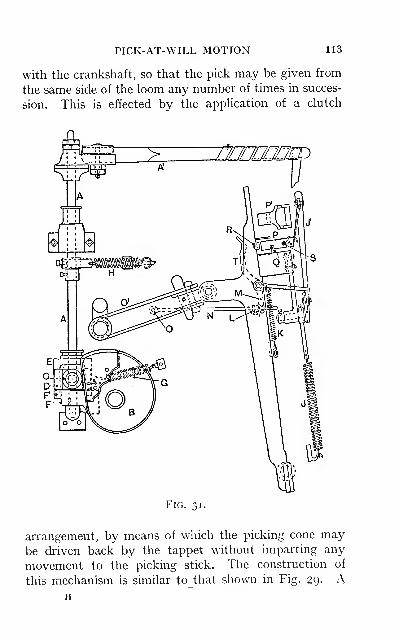
PICK-AT-WILL MOTION 113
with the crankshaft, so that the pick may be given from
the same side of the loom any number of times in succes-
sion. This is effected by the apphcation of a clutch
Fig. m
arrangement, by means of which the picking cone maybe driven back by the tappet without imparting any
movement to the picking stick. The construction of
this mechanism is similar tothat shown in Fig. 39. AH
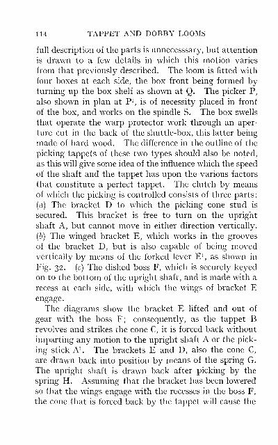
114 TAPPET AND DOBBY LOOMS
full description of the parts is unnecesssary, but attention
is drawn to a few details in which this motion varies
from that previously described. The loom is fitted with
four boxes at each side, the box front being formed byturning up the box shelf as shown at Q. The picker P,
also shown in plan at P^ is of necessity placed in front
of the box, and works on the spindle S. The box swells
that operate the warp protector work through an aper-
ture cut in the back of the shuttle-box, this latter being
made of hard wood. The difference in the outline of the
picking tappets of these two types should also be noted,
as this will give some idea of the influence which the speed
of the shaft and the tappet has upon the various factors
that constitute a perfect tappet. The clutch by meansof which the picking is controlled consists of three parts
:
(a) The bracket D to which the picking cone stud is
secured. This bracket is free to turn on the upright
shaft A, but cannot move in either direction vertically.
(b) The winged bracket E, which works in the grooves
of the bracket D, but is also capable of being movedvertically by means of the forked lever E^, as shown in
Fig. 32. (c) The dished boss F, which is securely keyed
on to the bottom of the upright shaft, and is made with a
recess at each side, with which the wings of bracket Eengage.
The diagrams show the bracket E lifted and out of
gear with the boss F; consequently, as the tappet Brevolves and strikes the cone C, it is forced back without
imparting any motion to the upright shaft A or the pick-
ing stick A^. The brackets E and D, also the cone C,
are drawn back into position by means of the spring G.
The upright shaft is drawn back after picking by the
spring H. Assuming that the bracket has been lowered
so that the wings engage with the recesses in the boss F,
the cone that is forced back by the tappet will cause the
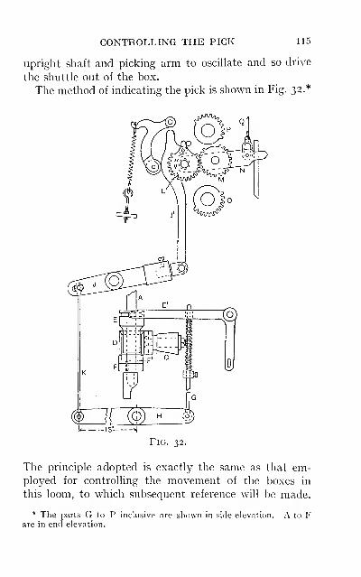
CONTROLLING THE PICK 115
upright shaft and picking arm to oscillate and so drive
the shuttle out of the box.
The method of indicating the pick is shown in Fig. 32.*
-13":*l
Fig. 32.
The principle adopted is exactly the same as that em-ployed for controlling the movement of the boxes in
this loom, to which subsequent reference will be made.
* The parts G to P inclusive are shown in side elevation. A to Fare in end elevation.
116 TAPPET AND DOBBY LOOMS
The fork lever E^ spanning the bracket E is operated bythe rod G and the lever H. This latter in turn is actu-
ated from the lever J, to which it is connected by the
rod K. The lever J is attached by a connector Ji to a
vibrator wheel L, which is in gear with the vibrator Msupported in the vibrator lever N. The vibrator M is
operated by the upper and lower semi-toothed cylinders
O and P respectively, into either of which it can be put
in gear through the medium of the connecting rod Q,which receives indication according to the pegging of the
box chain.
An objectionable feature of this type of picking
motion is the amount of force that must be expended in
order to destroy the energy contained in the various
springs which constitute part of the mechanism. Fromexperiments made, this force is in excess of that actually
required for driving the shuttle from box to box. In this
motion there are no fewer than five forces, in addition to
the resistance of the shuttle, to be overcome when picking
takes place—namely : The springs G, H and J (the latter
being used for drawing the picker clear of the boxes) ; the
pressure exerted on the shuttle when in the box, byreason of the swell spring and the stop-rod springs K;and the frictional resistance of the picker on the spindle.
The tuner should ever be alert to these factors, which are
present in every form of picking mechanism to a certain
degree, and should adopt every possible means to reduce
their opposing influences to the minimum.Shuttle-easing Motions.—It is with the object of
mitigating the above defect that shuttle-easing motions
have been introduced into certain types of picking
mechanism. Such a device is illustrated in Fig. 31. The
mechanism is simple in construction, and may be applied
to most looms fitted with a stop-rod as warp protector.
The stop-rod finger T is made with a projection M, which
PRESSURE ON THE SHUTTLE 117
is provided with an opening to admit the rod N. This
rod is supphed with an adjustable coUar L, and is pivoted
on the stud O fixed in the crank connecting arm O^. Fig.
31 shows the position of the several parts just as the pick
is about to take place. The crank-arm is at its lowest
point and the stud O in the near position to the stop-rod
finger. The collar L is set at such a distance from the
stud O as to push the projection M forward, and the stop-
rod finger T clear of the box swell. This reheves the
shuttle of the pressure exerted by the two stop-rod
springs K, as these are made fairly strong in order to keepthe stop-rod steady when the shuttle enters the box, or
when the loom knocks off. As the crank approaches
the back centre the action of the collar against the pro-
jection is gradually withdrawn by reason of the rod being
lifted into a position out of a straight line. This leaves
the stop-rod finger free to assist in checking the shuttle
as it enters the box.
Shuttle-checking Motion.—This motion has re-
ceived considerable attention during recent years, andseveral improvements have been introduced. Theprimary cause necessitating such improvements is the
gradual speeding-up of all types of power-looms, the in-
creased efficiency of the loom being obtained in this
direction, rather than by effecting any radical change in
its construction. The increase in the speed of a loom is
attended by a quicker movement of the shuttle, whichrequires more effective means for checking. This applies
more particularly to box looms, where the checking is notalternate as in the plain single-box loom. The mosteffective form of a checking motion is found in loomswhere the picking takes place from each side alternately.
This consists of a strap run along the front of the goingpart, extending from one box to the other. The strap is
first secured, in buckle form, to leather tags, which fit on
118 TAPPET AND DOBBY LOOMS
the spindle behind the picker. The ends of the strap are
fixed to the outer end of the shuttle-box by means
of the spindle spring or by a set-screw. The check
strap is left of such a length that when the shuttle enters
either box, the strap will be drawn in the same direction,
and so draws the picker forward at the opposite side
ready to check the shuttle as it is returned. With this
method the length of the check can be easily regulated,
whilst the checking of the shuttle is not influenced by any
variation of the pick. In looms where the checking is
required to take place at the same side a number of times
in succession, the above method is not applicable. Onsuch looms it is necessary to have the checking at each
side working independently of the other. This is accom-
plished by employing a short length of strap at each side,
one end being fastened to the tag on the spindle, and the
other end attached at some convenient point to the
breast beam. The strap is so adjusted for length and
position that when the going part recedes from the breast
beam, the strap and the picker are drawn forward. As
the going part approaches the breast beam they are then
drawn backwards by means of the switch stick Ji and the
spring J , Fig. 31. The shuttle, which enters the box at this
time, is gradually brought to a state of rest by contact
with the receding picker, irrespective of the side from
which picking has taken place. The objectionable
feature to this form of checking motion is that the check-
ing of the shuttle can be effectively done only when the
going part is in a certain position. As a result the pick
has to be regulated to suit the checking, and not, as is
desirable, the checking to the picking.
Recent inventions have aimed at overcoming this
difficulty, and at the same time obtaining a more effective
form of checking motion, by employing an eccentric to
control the checking strap. The eccentric is operated
RESULTS OF DEFECTIVE CHECKING 119
from some convenient part of the loom, usually the mainshaft, and possesses the advantage of allowing the check-
ing motion being set to suit the picking and speed of the
shuttle. This principle has been further developed byemploying an eccentric for each side of the loom, bymeans of which the checking is placed under separate
control.
Defective Checking.—This is responsible for the
pickers, shuttles, and strappings wearing out too quickly.
Defects in the piece are occasionally brought about bythe shuttle rebounding as the weft falls slack in the shed,
and during beating-up forms into small loops, varying in
size to the extent of the slack weft. This defect may also
be responsible for the weft stop-motion not working
satisfactorily. A more serious defect due to imperfect
checking is the stripping of the weft, which is an unneces-
sary waste of material and time. Faulty checking is
also frequently the cause of unsatisfactory picking.
Under - pick Motion.—A picking motion of the
under-pick type, which is employed on the well-known" Dobcross " loom, is illustrated in Fig. 33. Themechanism of this motion varies considerably from that
of the motions previously described. The picking arm Ais pivoted below the boxes on a stud B^ in the bracket B.
The arm extends upwards and works between the frame-
work of the box C and the picker spindle D, and is
directly behind the picker E, to which it is attached bymeans of a strap. The plan view shows the arrangement
of the shuttle-box, picker and spindle. The action of
the picking arm on the picker partakes of the nature of a
push along the spindle. The picker projects through the
aperture in the box framework, and makes contact with
the shuttle as shown. A swell F forms the front of the
box, which is built of steel and is fairly light but rigid.
The picking arm is actuated from the picking shaft G,
120 TAPPET AND DOBBY LOOMS
which in this instance makes one revolution per pick.
On this shaft are placed the picking tappets H, one at each
side of the loom; these carry a picking bowl J, and are
free to move along the shaft in a lateral direction only.
The tappets are constructed with two projections which
fit into the recesses of the picking block K, which, being
secured to the picking shaft, impart a rotary motion to
the picking tappet and the bowl. Below the picking
shaft and at right angles to it are placed the square
shafts L; these are supported in suitable bearings fixed
to the cross rails, as shown in the side elevation. Thesquare shafts are provided with a picking shoe M, directly
underneath the block K, and also with a lever N, to
which the picking arm is attached by means of the con-
nector and the strap O. The lateral movement of the
picking tappet is controlled by the forked lever P whichspans the grooved collar on the tappet. The lever P re-
ceives motion from the rod Pi and the pick jack P-, whichis actuated from the vibrator Q, to which it is coupled bymeans of a connector Q^.
The pick may take place a number of times in succes-
sion from either side of the loom, according as the picking
bowl is drawn over or away from the picking shoe. This
is governed by a pulley or blank in the pattern chain,
which puts the vibrator Q in gear with either of the semi-
toothed cylinders R or Ri respectively.
A modification of this picking motion has recently been
introduced, the object of which has been to facilitate an
increase in the speed of the loom. The motion has been
converted into a whip pick, and the box motion has also
been improved by making it positive in action whetherthe boxes are being lifted or depressed. These improve-
ments have rendered an increase of lo per cent, in speed
an easy matter. The chief feature of this improvementconsists in the substitution of a clamp bracket in place
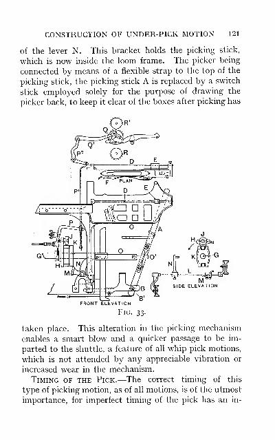
CONSTRUCTION OF UNDER-PICK MOTION 121
of the lever N. This bracket holds the picking stick,
which is now inside the loom frame. The picker being
connected by means of a flexible strap to the top of the
picking stick, the picking stick A is replaced by a switch
stick employed solely for the purpose of drawing the
picker back, to keep it clear of the boxes after picking has
FRONT ELEVATION
Fig. 33.
taken place. This alteration in the picking mechanism
enables a smart blow and a quicker passage to be im-
parted to the shuttle, a feature of all whip pick motions,
which is not attended by any appreciable vibration or
increased wear in the mechanism.
Timing of the Pick.—The correct timing of this
type of picking motion, as of all motions, is of the utmost
importance, for imperfect timing of the pick has an in-
122 TAPPET AND DOBBY LOOMS
jurious effect on the working of the loom. It is important
to note that the crankshaft in this loom works up from
the bottom centre towards the weaver. To time the
pick, turn the loom to bring the crank to the top centre.
When in this position the picking bowl should be im-
pinging on the shoe, and graduahy depressing it, drawing
the connector strap tight until the picker is in contact
with the shuttle tip, and ready for the accelerated move-
ment being imparted. The shuttle will then enter the
shed when the going part is about one inch from the back
position. The connector strap O should always be kept
as near as possible the same length, with the object of
presenting the picking shoe to the bowl in the same rela-
tive position. If the connector strap is too long, the
bowl cannot engage with the shoe at the same time and
place, consequently the action of the pick becomes jerky,
though not necessarily stronger, as is sometimes sup-
posed. To allow of any alteration in the timing of the
pick, the picking bowl stud is secured in the concentric
slot of the tappet H. By this means the bowl may be
put forward or backward according to requirements.
Setting the Pick.—The strength of the pick in this
motion can be regulated by (a) altering the position of the
connector strap O^ on the picking stick, raising or lower-
ing to decrease or increase the stroke of the stick;
(b) an
alteration in the position of the stud B^ in the bracket B
;
(c) moving the picking shoe along the shaft to bring it
more directly underneath the picking bowl (this will
increase the pick) , or moving it farther back to reduce the
pick. Any alteration here will also affect the timing of
the pick slightly.
Early and Late Picking.—All picking motions are
constructed with the object of affording scope for timing
the pick. This is essential since the timing of the pick
is often influenced by the timing of the shedding motion,
DEFECTIVE PICKING 123
and in some instances to a slight extent by the box motion.
Early picking is practised in order to facilitate early
shedding, for reasons already given on a previous page.
Occasionally it is advantageous when weaving with
tender weft or badly spun weft cops to time the picking
a little earlier. This gives the shuttle more time to travel
across the race, and the pick need not be as strong, so
that a gentler action is applied to the weft as it is drawing
off the cop. Late picking is sometimes adopted to allow
the boxes a little more time to arrive at a state of rest
before picking takes place. Usually late picking is
resorted to in order to increase the force of the pick.
This is bad practice, since late picking is always harsher
the nearer the crank is to the back centre when the actual
blow is delivered. This is attended by considerable
friction, especially in the driving wheels, in which, if the
teeth are not broken, they quickly wear out. When the
teeth are worn down in this way there is always an
amount of backlash when picking takes place, resulting
in a jerky motion being transmitted to the going part.
This defect has occasionally been remedied by having a
new keyway cut in the wheel, or a new keybed cut in the
shaft, in such a position as to bring an unworn portion of
the wheels in gear when picking takes place.
Defects in Picking Motions.—A defect common to
all picking motions is due to the mechanism becoming" picker-bound." This is brought about by reason of
the picker being drawn in close contact with and bearing
heavily against the buffer before the tip of the tappet
nose has passed the cone in the " over-pick " type, or the
picking bowl clear of the shoe in the " under-pick " type.
When picking takes place, the picker should have suffi-
cient play to move freely along the spindle. This can
only be effected by carefully setting the picking stick in
position, and by proper adjustment in the length of the
124 TAPPET AND DOBBY LOOMS
connecting strap. Whenever any alteration is deemednecessary the loom should be turned over by hand to
ascertain the extent of the chase given to the picker.
This defect is mainly responsible for the expense incurred
in the renewal of pickers, strappings, and picking sticks.
It is also a fruitful source of broken cone studs or strained
studs. The latter lock the cone and prevent it from
rotating, so that a flat is worn on the surface, which,
when the cone is released, produces imperfect picking.
The upright picking shafts and the low shaft pedestals in
the over-pick type are frequently broken by reason of the
above defect, whilst the square shafts are broken or
twisted, and occasionally the picking tappets broken, in
the under-pick type.
Tight and Slack Shuttle-boxes.—This is a defect
which occasions a considerable amount of trouble in the
working of the loom, and is always a harassing problem
to the tuner. Such a defect is often accentuated by some
slight discrepancy in the construction of the shuttle.
Providing the shuttles are accurate in shape and all of the
same size, then with the boxes set to the same gauge the
shuttles are interchangeable and fit each box correctly.
Occasionally the boxes are tightened to assist in checking
the shuttle. This is to be discountenanced, as the pick-
ing motion has to overcome this increased friction whendriving the shuttle out of or into a tight box. Too tight
a shuttle-box may be the cause of the shuttle flying out
;
whilst, if the box is too slack, the shuttle will rebound and
cause the loom to knock off, or the shuttle may be trapped
in the shed. Tight shuttles are very frequently the cause
of the boxes not working satisfactorily. If, when the boxes
are being lifted or depressed, the tip of the shuttle comes
in contact with the picker or the regulating bowls, and
the shuttle is held unduly tight in the box, it is unable to
slide forward clear of the obstruction, and so prevents the
WASTE OF WEFT 125
boxes from working. A shuttle which fits slackly in the
box, and not being required to run frequently in the
wefting plan, may gradually work forward to the front of
the box by reason of the vibration; when this par-
ticular shuttle is required in the order of the wefting, the
loom will probably knock off.
Waste of Weft.—Stripped weft and damaged weft
cops are a direct loss to the manufacturer, and a vigilant
eye should be kept on the weavers' waste to ascertain the
proportion which may be traced directly to this source.
Apart from the building of the weft cops during their
preparation for the weaver, there are causes in the
loom to which this defect may be due
—
e.g., too strong a
pick, imperfect checking, and tight shuttle-boxes. This
defect is no doubt encountered in its worst form whenweaving woollens of a medium or low quality. The weft
is usuaUy spun on to a bobbin, and in some instances in
cop form on to a bare spindle. The strength of the yarn
does not always allow of the weft cops being made hard
and firm enough to withstand the usage to which they are
exposed during weaving; consequently the weft is easily
stripped or damaged beyond the possibility of its being
woven. That stripping of the weft invariably takes
place at one side of the loom is a feature to be noticed
—
i.e., when the shuttle is travelling in the direction in
which the nose of the weft cop is pointing. If the shuttle
is brought to an abrupt stop by reason of any of the
above-mentioned causes, the tendency can only be for the
weft to slip off the bobbin, or in the case of weft cops they
are liable to buckle and break by the impact. When the
shuttle is moving in the opposite direction, the weft is
forced tighter on to the bobbin, and only in rare cases are
the weft cops damaged. Weft stripping has been brought
about by a renewal of one of the pickers, which was re-
newed at the side of the loom referred to. The new picker
126 TAPPET AND DOBBY LOOMS
being harder and firmer than the old one, increased the
force of the impact and caused the weft to strip. This can
be usually remedied in looms where the pickers are inter-
changeable, by putting the new picker on at the opposite
side, and using the partly worn picker in lieu of a new
one. By this means a counteracting action is imparted
to the weft on the bobbin as it enters opposite boxes.
Pickers and Picking Straps.—Considerable re-
duction in the expenses caused by renewals in the picking
motion may be effected by attention to minor details.
The picking straps should be well conditioned before
being used. The groove made in the picking stick to
accommodate the strap should be quite smooth, and the
picker where the strap is attached to it should be free
from the sharp edges occasionally left on during its con-
struction. Pickers should be thoroughly seasoned before
using, and on no account should they be put into
use if they possess the appearance of being in a state
approaching absolute dryness; when pickers are used
in this condition they are liable to break rather than
wear. The condition of a picker can be fairly determined
by the handle and its weight ; a light picker is usually
a very dry one. Pickers may be conditioned by im-
mersing them in oil for a period of from six to eight weeks.
They are then hfted out and allowed to drain for the same
period in a temperate atmosphere. The durability of a
picker is increased by the free use of buffer bits; these
are placed on the spindle to serve as a cushion for the
picker. The buffer should be connected to a strap in
order to give a certain amount of resilience, and it should
not be allowed to be driven into a solid mass against the
spindle stud. Large numbers of pickers are supplied to
the tuner with the socket smaller than is actually required
by the diameter of the spindle. The sockets are some-
times enlarged by burning them out with a red-hot spindle
BORING THE PICKERS 127
of the requisite dimensions. Occasionally an ordinary
brace and taper bit is employed for this purpose; but
this is a very unsatisfactory method, especially if the
taper of the bit is very acute. The bit must be forced
far enough to clear the inside of the socket; the outside
will then be too large for the spindle. This reduces the
wearing surface, as the socket in the picker soon becomes
too large for the spindle, with the result that the passage
of the shuttle is affected, and the picker requires morefrequent renewal.
CHAPTER VI
SHUTTLE-BOX MECHANISM
Box Motions.—The box motion is an accessory to those
power-looms adapted for the purpose of weaving cloths
in which more than one colour or quality of weft is used,
such looms having a greater scope for figuring in the weft.
There is therefore some analogy between the capacity
for figuring in the weft in the various types of boxmotions and the capacity for figuring in the warp in the
various types of shedding motions. Plain looms are
sometimes provided with two boxes at one side and a
single box at the other—such a loom is usually re-
ferred to as a " Bastard " loom. Plain looms may be
provided with two boxes at each side, but obviously the
wefting capacity of such looms is very limited, since com-
plicated wetting plans cannot be woven. These looms
are mainly employed for weaving plain goods in which
more than one shuttle is used merely to mix the weft.
The shuttles are picked two-and-two, or in the loom pro-
vided with two boxes at each side, three shuttles could be
employed and the weft run in three odd picks. The ad-
vantage accruing from this arrangement is that a better
distribution of the weft takes place, which reduces shadi-
ness in the piece due to faulty or uneven yarn. In looms
for weaving fancy goods a more comprehensive box
motion is necessary. On such looms there are two classes
of box motions adopted—namely, the circular box
motion and the rising or drop box motion. The main
128
FEATURES OF BOX MOTIONS 129
feature of difference between the two classes is found in
the method of carrying the shuttles. In the circular box
motion the shuttles are accommodated in a series of cells
arranged in circular form around a common axis on
which they revolve. In the other class the boxes are
arranged in shelf form one above the other. This class
of box motion may be either of the rising or drop box
type, according to the mechanism employed for controll-
ing the boxes. Such motions are usually constructed with
four boxes at each side, which are capable of being
operated so as to yield practically every order of wefting
;
the picking motion being constructed on the " pick-at-
will " principle. The following factors should be in
evidence in a good box motion: Each set of boxes must
work independently of the other; any box at either side
should be readily brought into operation, irrespective of
its former position; the boxes should be easily adjusted
for height with respect to the race ; the box and pattern
chains should be worked from the same cylinder ; and the
motion should be positive, but provided with an efficient
escape or safety motion.
Most box motions of this latter class are worked on the
lever principle ; the levers being compounded in such pro-
portions with respect to their fulcra and relative leverage
as to impart the requisite movement to the various boxes.
A type of rising box motion is illustrated in Fig. 34.
The boxes A form a rectangular block, and are provided
with a tongue at each side which works in the two slides
B and C of the framework. The boxes rest on the fork D,
through which the box rod E passes, this being secured to
the lug underneath the bottom box shelf. The rod Epasses downward through the spiral spring F and the
tube G, and is held in position by means of the lock-nuts
H. Each set of boxes is controlled by two levers J and Kto which they are connected by means of the chain L.
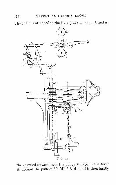
130 TAPPET AND DOBBY LOOMS
The chain is attached to the lever J at the point Ji, and is
then carried forward over the pulley M fixed in the lever
K, around the pulleys M^ M^. M^, M^, and is then finally
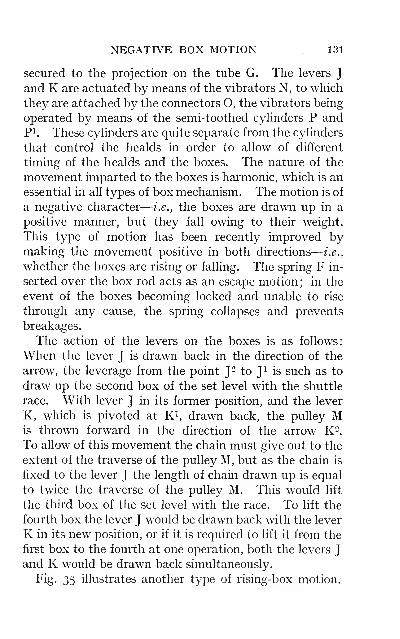
NEGATIVE BOX MOTION 131
secured to the projection on the tube G. The levers Jand K are actuated by means of the vibrators N, to which
they are attached by the connectors O, the vibrators being
operated by means of the semi-toothed cyhnders P andPi. These cyhnders are quite separate from the cyhnders
that control the healds in order to allow of different
timing of the healds and the boxes. The nature of the
movement imparted to the boxes is harmonic, which is an
essential in all types of box mechanism. The motion is of
a negative character
—
i.e., the boxes are drawn up in a
positive manner, but they fall owing to their weight.
This type of motion has been recently improved bymaking the movement positive in both directions
—
i.e.,
whether the boxes are rising or falling. The spring F in-
serted over the box rod acts as an escape motion ; in the
event of the boxes becoming locked and unable to rise
through any cause, the spring collapses and prevents
breakages.
The action of the levers on the boxes is as follows:
When the lever J is drawn back in the direction of the
arrow, the leverage from the point J ^ to Ji is such as to
draw up the second box of the set level with the shuttle
race. With lever J in its former position, and the lever
K, which is pivoted at Ri, drawn back, the pulley Mis thrown forward in the direction of the arrow K^^
To ahow of this movement the chain must give out to the
extent of the traverse of the pulley M, but as the chain is
fixed to the lever J the length of chain drawn up is equal
to twice the traverse of the pulley M. This would lift
the third box of the set level with the race. To lift the
fourth box the lever J would be drawn back with the lever
K in its new position, or if it is required to lift it from the
first box to the fourth at one operation, both the levers Jand K would be drawn back simultaneously.
Fig. 35 illustrates another type of rising-box motion.
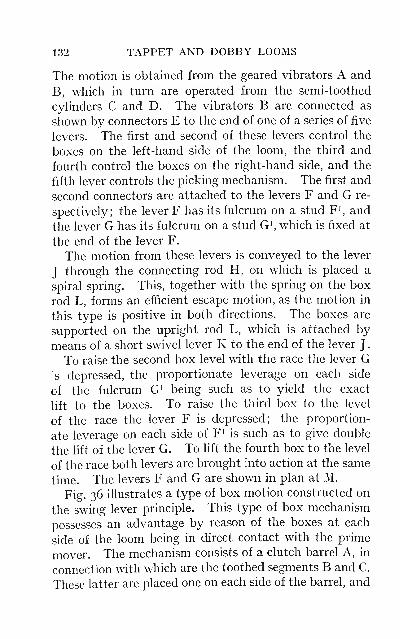
132 TAPPET AND DOBBY LOOMS
The motion is obtained from the geared vibrators A and
B, which in turn are operated from the semi-toothed
cylinders C and D. The vibrators B are connected as
shown by connectors E to the end of one of a series of five
levers. The first and second of these levers control the
boxes on the left-hand side of the loom, the third and
fourth control the boxes on the right-hand side, and the
fifth lever controls the picking mechanism. The first and
second connectors are attached to the levers F and G re-
spectively; the lever F has its fulcrum on a stud F^, and
the lever G has its fulcrum on a stud G^, which is fixed at
the end of the lever F.
The motion from these levers is conveyed to the lever
J through the connecting rod H, on which is placed a
spiral spring. This, together with the spring on the box
rod L, forms an efficient escape motion, as the motion in
this type is positive in both directions. The boxes are
supported on the upright rod L, which is attached by
means of a short swivel lever K to the end of the lever J
.
To raise the second box level with the race the lever Gs depressed, the proportionate leverage on each side
of the fulcrum G^ being such as to yield the exact
lift to the boxes. To raise the third box to the level
of the race the lever F is depressed; the proportion-
ate leverage on each side of F^ is such as to give double
the lift of the lever G. To lift the fourth box to the level
of the race both levers are brought into action at the same
time. The levers F and G are shown in plan at M.
Fig. 36 illustrates a type of box motion constructed on
the swing lever principle. This type of box mechanism
possesses an advantage by reason of the boxes at each
side of the loom being in direct contact with the prime
mover. The mechanism consists of a clutch barrel A, in
connection with which are the toothed segments B and C.
These latter are placed one on each side of the barrel, and
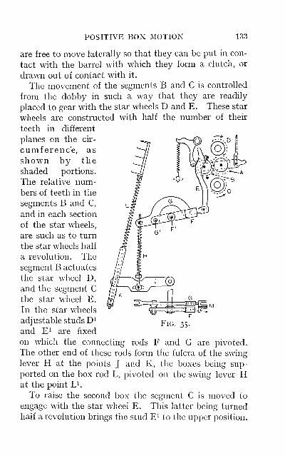
POSITIVE BOX MOTION 133
are free to move laterally so that they can be put in con-
tact with the barrel with which they form a clutch, or
drawn out of contact with it.
The movement of the segments B and C is controUed
from the dobby in such a way that they are readily
placed to gear with the star wheels D and E. These star
wheels are constructed with half the number of their
teeth in different
planes on the cir-
cumferenc'e, as
shown by the
shaded portions.
The relative num-bers of teeth in the
segments B and C,
and in each section
of the star wheels,
are such as to turn
the star wheels half
a revolution. Thesegment B actuates
the star wheel D,
and the segment Cthe star wheel E.
In the star wheels
adjustable studs D^
and El are fixed
on which the connecting rods F and G are pivoted.
The other end of these rods form the fulcra of the swing
lever H at the points J and K, the boxes being sup-
ported on the box rod L, pivoted on the swing lever Hat the point L^.
To raise the second box the segment C is moved to
engage with the star wheel E. This latter being turned
half a revolution brings the stud E^ to the upper position.
Fig. 35.
134 TAPPET AND DOBBY LOOMS
The traverse of the stud in combination with the
leverage of H, whicli now has its fulcrum at point K,
is such as to lift the second box to the level of the
race. To raise the third box, the star wheel E being
in its former position, the segment B is moved to
engage with the star wheel D. The stud D^ in this
wheel has a greater traverse than the stud E^, and this
in combination with the lever H, which now has its
fulcrum at point J, lifts up the third box to the level
of the race. To raise the fourth box to the level of
the race a combination of the above motions is per-
formed simultaneously.
Setting the Boxes.—It is of the utmost importance
that the boxes rise level with the shuttle race, and pro-
vision is made for adjusting their traverse at various
points in the mechanism. The setting of the boxes is
often a harassing duty of the tuner. This is due to the
levers in the various box motions being compounded in
such a way that any alteration at one or other of the vari-
ous points has an effect on other boxes of the set besides
the one it is desired to regulate. Owing to this feature the
setting of the boxes cannot be determined by " rule of
thumb." Any alteration necessary should be carried
out carefully, noting the influence that any alteration at
a given point will have upon the whole set of boxes on
that particular side. To deviate from this method of
setting only results in alterations first at one point and
then at another, until by mere chance the correct position
is obtained.
A common cause of the boxes being out of truth is due
to their irregular use. Frequently the loom is run for
long periods with only the first and second boxes at one or
both sides in use. Thus the surface of the studs, pulleys
and chains wears down at particular points, and, as a
result, when the other boxes are brought into operation
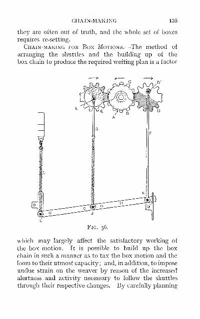
CHAIN-MAKING 135
they are often out of truth, and the whole set of boxes
requires re-setting.
Chain-making for Box Motions.—The method of
arranging the shuttles and the building up of the
box chain to produce the required wefting plan is a factor
Fig. 36.
which may largely affect the satisfactory working of
the box motion. It is possible to build up the boxchain in such a manner as to tax the box motion and the
loom to their utmost capacity ; and, in addition, to impose
undue strain on the weaver by reason of the increased
alertness and activity necessary to follow the shuttles
through their respective changes. By carefully planning
136 TAPPET AND DOBBY LOOMS
out the box chain, the above result can, however, be
frequently avoided, and the desired movement to the
various boxes obtained with the expenditure of a mini-
mum of power.
Features in Chain-making.—The following features
should be observed when building up a box chain: (a)
Each shuttle in the wetting plan should be brought into
sight as often as possible—by preference into the top box
on that side of the loom on which the weaver stands to
change the shuttles, (b) Those shuttles which run most in
the wetting plan, or those in which the cops run off most
frequently
—
e.g., as in a backed or double cloth made with
thick woollen weft for the backing yarn—should be
planned to run into sight in order to enable the weaver
to catch the weft before it is fully spent, (c) Each shuttle
should be kept to its own box as far as is practicable,
since this renders it easier for the weaver to follow the
order of running, and is of assistance when placing the
shuttles in their respective order after lagging back for
broken weft or other defects in the piece. Attention to
this feature is specially essential when the wetting plan
contains two or more colours or qualities of weft which are
very similar in character, (d) Double and treble movesshould be avoided as much as possible ; in a negative box
motion a double or treble lift is preferable to a double or
treble drop, (e) When a double or treble move takes
place it is best to have the shuttle picking into the box on
that side, since this allows more time for the boxes to
attain a state of rest ready to receive the incoming shuttle.
(/) The boxes should be balanced
—
i.e., when the boxes on
each side of the loom are changing at the same time, they
should be balanced by one set being lifted and the other
set lowered; less power is absorbed by this method,(g)
The complete working of the shuttles should be arranged
with a view to maintaining uniform tension on the lists
METHODS OF CHAIN-MAKING 137
of the piece whilst the wefts are running off at different
times. This may often be impracticable, so far as the
arrangement of the box chain is concerned, but it may be
largely regulated by the weaver effecting an occasional
change of the shuttles
—
i.e., replacing a half-spent weft
cop by a full one. (h) The complete repeat of the wetting
plan should be worked out by giving as few movements as
possible to the boxes, consistent with the foregoing rules.
Building up Box Chains.—A very common methodby which the experienced chain-maker determines the
order of working the boxes is by first passing over, from
one side to the other, into imaginary boxes, different sizes
or forms of tokens, usually metal discs, numbered to re-
present the various shuttles to be employed. Havingobtained a complete repeat of the wetting plan in this
manner, the box chain is built up, and at the same time
the tokens are passed over from side to side as a check on
the work. This is no doubt as expeditious a method as it
is possible to adopt for the experienced operative, but an
objection is found in the fact that no record of the run-
ning of the shuttles, or of a box-chain plan, is kept for
future reference. This is very desirable when the wetting
plan is complicated, as frequently the chain cannot be
kept intact after use, but its components are again used
in the construction of a box chain for some other wetting
plan. After a time the original box chain may be again
required, as is occasioned by a repeat order for that par-
ticular cloth. The former order of procedure in building
up the box chain is again necessary, and this operation in
case of a complex wetting plan may take up more time
planning the order of running the shuttles than is taken
to build up the actual chain. A further advantage of
keeping a box-chain plan of the running of any particu-
lar wetting plan is that the plan could be given to an
inexperienced operative, who could build the box chain

138 TAPPET AND DOBBY LOOMS
from it in a similar manner to pegging the lags for the
healds from the point-paper plan of the design.
The following " paper " method of illustrating box-
Left.
4th
BUILDING UP BOX CHAINS 139
the levers for the box motion shown in Fig. 34, but it will
also serve as an illustration for most modern box motions,
the only necessary alteration being in the position of the
levers employed for controlling the respective boxes.
On the box-chain pin there are spaces for five tubes or
pulleys, the effect of placing pulleys in any of these
spaces being shown in Fig. 37, as follows: The spaces are
numbered i to 5. With No. i space left blank the pick
would take place from the right-hand side of the loom ; a
pulley placed in this space causes the loom to pick from
the left-hand side. A pulley placed in the space No. 2
indicates for the second box on the right ; a pulley in the
space No. 3 indicates for the third box on the right ; whilst
pulleys placed in both the spaces Nos. 2 and 3 indicate
for the fourth box on the right. Similarly for the boxes
on the other side of the loom, a pulley in the space No. 5
indicates for the second box on the left; a pulley in the
space No. 4 indicates for the third box on the left; and
pulleys placed in both the spaces Nos. 4 and 5 indicate
for the fourth box on the left. This principle of chain-
making is further illustrated by the boxing plan in
Fig. 38, made out for the wetting plan given. This
only requires two shuttles and two boxes on each side
;
the boxes are numbered i, 2, 3, 4 on the left-hand,
and 4, 3, 2, I on the right-hand sides respectively. Theshuttles at the commencement are shown placed in boxes
Nos. I and 2 on the left-hand side. The order of running
is indicated by means of the crosses and letters
—
the
crosses denote the shuttle leaving the box on that side,
the letters indicating the box to which it is sent on the
opposite side.
The shuttle A is indicated as being sent from No. i box
on the left to No. i box on the right, then back again to
No. I box on the left, giving two successive picks from
the shuttle A. The second box on each side is next lifted,
140 TAPPET AND DOBBY LOOMS
and the shuttle B is indicated as being sent from No. 2
box on the left to No. 2 box on the right. The shuttles
are sent from side to side in this manner until they have
completed one repeat of the wefting plan.
The position of the shuttles at this stage leads to a con-
sideration of an important factor in chain-making. It
will be seen that the shuttles after completing one repeat
of the wefting plan are on the opposite side from which
they commenced. To make up the box chain for this
repeat only, would not give a succession of repeats of the
wefting plan. For instance, the first lag of the box chain
would be made up to pick the shuttle A from the left-
hand side of the loom, the same lag coming round on the
lag cylinder to indicate again for the first pick of the weft-
ing plan. But, as already pointed out, the shuttle A is
now on the right-hand side of the loom, consequently the
next lag of the box chain—viz., the seventh—must be built
up to pick from the right-hand side ; and similarly for the
shuttle B ; and the shuttles run for another repeat of the
wefting plan in order to bring them back to their original
position. This necessitates the box chain being madeon 12 lags, or twice the number of picks in the wefting
plan.
This obtains for all wefting plans in which an odd
number of picks is required from any one colour or quality
of the wefts composing the repeat. For instance, a
simple wefting plan is as follows:
49 picks black_. . .1^50
1 pick fancy twist . . J
This wefting plan is complete on 50 picks, but the box
chain will repeat at 100 on account of the odd pick of
fancy twist.
This feature in chain-making is responsible for the use
of excessively long box chains. To obviate this objec-
tionable feature, the picking mechanism of some looms
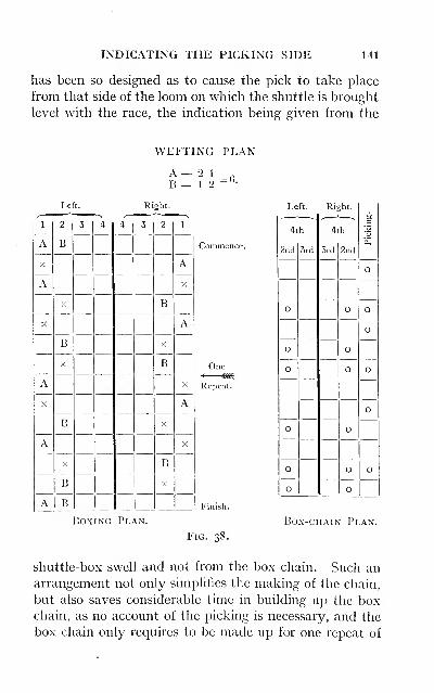
INDICATING THE PICKING SIDE 141
has been so designed as to cause the pick to take place
from that side of the loom on which the shuttle is brought
level with the race, the indication being given from the
WEFTING PLAN
A— 2 1
B — 1 2= G.
Left. Right.
1
A
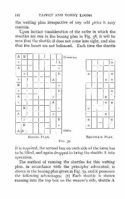
142 TAPPET AND DOBBY LOOMS
the wefting plan irrespective of any odd picks it maycontain.
Upon further consideration of the order in which the
shuttles are run in the boxing plan in Fig. 38, it will be
seen that the shuttle B does not come into sight, and also
that the boxes are not balanced. Each time the shuttle
A
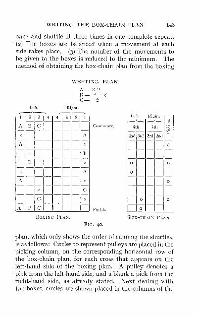
WRITING THE BOX-CHAIN PLAN 143
once and shuttle B three times in one complete repeat.
(2) The boxes are balanced when a movement at each
side takes place. (3) The number of the movements to
be given to the boxes is reduced to the minimum. Themethod of obtaining the box-chain plan from the boxing
WEFTING PLAN.
A —B —C—
Left. Right.
1
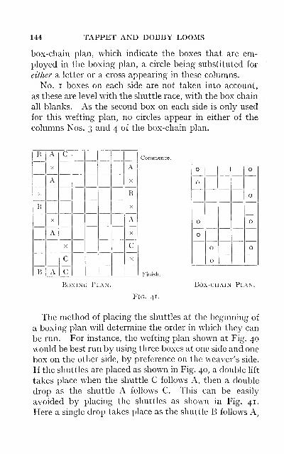
144 TAPPET AND DOBBY LOOMS
box-chain plan, which indicate the boxes that are em-
ployed in the boxing plan, a circle being substituted for
either a letter or a cross appearing in these columns.
No. I boxes on each side are not taken into account,
as these are level with the shuttle race, with the box chain
all blanks. As the second box on each side is only used
for this wetting plan, no circles appear in either of the
columns Nos. 3 and 4 of the box-chain plan.
Commence.B
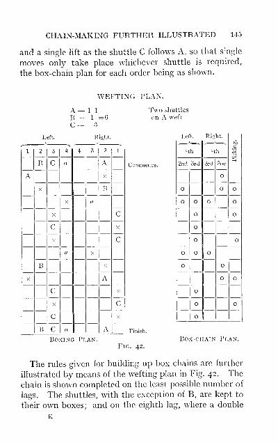
CHAIN-MAKING FURTHER ILLUSTRATED 145
and a single lift as the shuttle C follows A, so that sngle
moves only take place whichever shuttle is required,
the box-chain plan for each order being as shown.
WEFTING PLAN.
1 1
1 :
3
Two shuttles
on A weft
Left. Right.
1
146 TAPPET AND DOBBY LOOMS
drop takes place
—
i.e., from the fourth to the second box
on the left—the shuttle is picking inwards.
The defects of this chain are: (i) The boxes are not
balanced, as lifts and drops take place on each side
simultaneously. (2) The shuttle (a) is run " blind," this
term being applied to those shuttles which do not showin either the top or second box on the weaver's side of the
loom. Fig. 43 shows an alternative method of running
the shuttles for this wetting plan ; and although the chain
occupies double the number of links as in Fig. 42, it
possesses advantages over the former chain in that (i) the
boxes are much better balanced; (2) the shuttles run into
sight of the weaver more; and (3) only three boxes oneach side of the loom are employed.
The above examples illustrating the principles of build-
ing up box chains are taken from simple orders of wetting
;
but they cannot be taken as representing the general run
of wetting plans, nor do they indicate the intricacies
encountered in the operation. It is only when box chains
have to be made for wetting plans which necessitate five
or more shuttles that the real difficulties are apparent.
Frequently the tuner and the weaver have to adopt
some plan in order to deal with the difficulties which arise
in running the shuttles. For example, a wetting plan
may be such that four boxes are not sufficient to allow of
the necessary changes being made by the box motion.
By the weaver effecting, however, a change of the shuttles
(by preference those which carry the wefts for the over-
checking, which is known as " planting " the shuttles),
the running of the wetting plan is made possible. This
is more frequently the case when weaving large check
patterns, in which alternate overcheckings are of different
colours. It is possible, when the checking shuttles are
run into the bottom box at either side, to make an attach-
ment to the starting lever, in order to throw off the loom
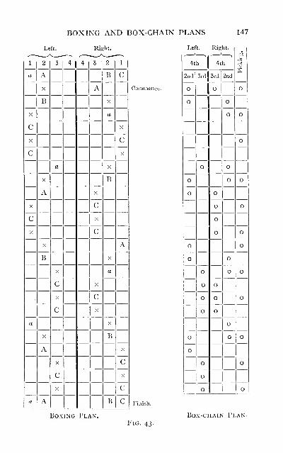
BOXING AND BOX-CHAIN PLANS 147
Left. Right.
1
148 TAPPET AND DOBBY LOOMS
when that box is Hfted. This reheves the weaver fromtracing the shuttles to that particular point in the plan in
order to effect the change of shuttles by hand. Another
method by which large checking plans have been run is to
return one or other of the checking shuttles back again
over the top of the warp. This necessitates the numberof pattern lags for the healds being increased to, say, half
the number of links contained in the box chain ; lengths
of pattern lags made up for the simple and standard
weaves being kept in stock for this purpose. A blank
pattern lag would be inserted to drop all the healds on
the corresponding pick in the box chain which returns the
shuttle.
When the pattern lags are increased to only half the
number of the box lags, one of the other shuttles must be
sent over the top of the warp when the blank lag in the
heald pattern comes round. Under certain conditions
this would be an advantage, and tend further to facilitate
the building up of the box chain to prevent any changing
of the shuttles by hand. Pattern lengths and pieces
have been woven in this manner, but such plans are the
exception to the general run of the fabrics woven on
looms built with four boxes.
Complicated Weft Plans.—These are of two kinds:
(a) Those in which i or 2 colours, in addition to the
ground shades, are employed; but owing to the desira-
bility of using two or more shuttles on the ground
shades, for the purpose of mixing the weft, building upof the box chain is rendered more difficult. An example
of this is shown in the following progressive wetting plans
obtained from a simple check made up of 6 black, 6
white : (i) It is usual to employ two shuttles for the black
weft. (2) Occasionally two shuttles are run on both the
black and the white, the order of wetting being i-and-i,
from the respective shuttles. (3) The colouring of the
DIFFICULT BOX CHAINS 149
fabric may be altered by the addition of a single coloured
thread as an overcheck. (4) Or by the addition of two
single coloured threads as overchecks. (5) Converting
the single cloth into a weft backed or double cloth, with a
different colour or quality of yarn on the back. The final
wetting plan, unless specially modified, would in such
cases exceed the range of a four-box loom.
Such wetting plans are, however, more easily dealt with
than those in which each shuttle carries a different weft,
and which must be taken in a given order. The reason
for this is that shuttles carrying similar wefts need not
be run so as to take an equal number of picks off each, in
one repeat of the wefting plan ; but either of them taken
as is the most convenient to facilitate the running of the
checking and the backing shuttles as they are required in
the plan.
(b) Wefting plans in which several colours or wefts are
employed, the following being an example showing the
developments :
—
3 threads of shade I. )
3 III3 " "
J*
r =12, colouring for the ground.
3 " ]] III.)
To such a checking pattern a single or double overcheck
may have been added, or, as is frequently the practice, a
backing weft, and occasionally a wadding weft, as in
heavy overcoatings and motor cloths. When dealing
with this type of wefting plan the limitation of a four-
box loom is soon exceeded, by reason of the ground shades
all running in odd picks. For such goods as the above,
check backs and fancy tweeds, looms provided with six
boxes at each side are employed.
Circular Box Motion.—This class of box motion is
invariably adopted on quick-running looms of light andmedium build, and is employed in the production of fancy
150 TAPPET AND DOBBY LOOMS
fabrics, such as check dress goods, tartan patterns, check
linings, cotton handkerchiefs, and small woollen shawls.
These fabrics are made from yarn of fine and mediumcounts to produce cloths up to a medium weight. Loomsprovided with a circular box motion are not constructed
to employ a large shuttle, on account of the high speed
and the shuttle-box space available; consequently they
are unsuitable for weaving thick weft yarns, as changes
would be too frequent ; nor for weaving heavy cloths, as
such looms being fitted with a '' loose reed " as the warp
protector motion are not adapted to this class of fabric.
Large numbers of these looms are fitted with boxes at
one side of the loom only, usually six boxes in the set,
and a single box at the other side. Such an arrangement
reduces the weft figuring capacity of the loom by reason
of the shuttle having to run in an even number of picks
;
nor would any advantage accrue if a set of boxes were
placed at each side, unless the loom was constructed on
the pick-at-will principle. The mechanism for operating
the boxes is of two different types: (a) The mechanism
may be such that the boxes can only be turned one box
forward or one box backward at any given move. This
restricts the capacity of the motion, as only those wetting
plans which run in symmetrical order can be woven
—
i.e.,
the shuttle containing the weft next required must always
be in the box, forward or backward, adjoining the running
shuttle, [b) Skip-box mechanism, which is so constructed
that any box of the set can be brought level with the
shuttle race, irrespective of its position to the box last
used. The construction of the former type of motion is
illustrated in Fig. 44. The boxes A are arranged in
circular form, and are supported at the outer end on a
spindle B, and at the front by means of a circular iron
band. Fixed to the spindle is a pegged disc B^, the pegs
being equal distances apart, one peg for each of the six
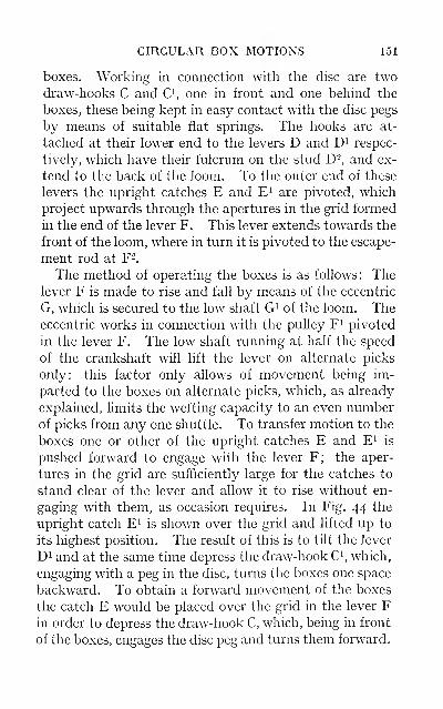
CIRCULAR BOX MOTIONS 151
boxes. Working in connection with tlie disc are two
draw-hooks C and C^, one in front and one behind the
boxes, these being kept in easy contact with the disc pegs
by means of suitable flat springs. The hooks are at-
tached at their lower end to the levers D and D^ respec-
tively, which have their fulcrum on the stud D^, and ex-
tend to the back of the loom. To the outer end of these
levers the upright catches E and E^ are pivoted, which
project upwards through the apertures in the grid formed
in the end of the lever F. This lever extends towards the
front of the loom, where in turn it is pivoted to the escape-
ment rod at F-.
The method of operating the boxes is as follows: Thelever F is made to rise and fall by means of the eccentric
G, which is secured to the low shaft G^ of the loom. Theeccentric works in connection with the pulley F^ pivoted
in the lever F. The low shaft running at half the speed
of the crankshaft will lift the lever on alternate picks
only: this factor only allows of movement being im-
parted to the boxes on alternate picks, which, as already
explained, limits the wetting capacity to an even numberof picks from any one shuttle. To transfer motion to the
boxes one or other of the upright catches E and E^ is
pushed forward to engage with the lever F; the aper-
tures in the grid are sufficiently large for the catches to
stand clear of the lever and allow it to rise without en-
gaging with them, as occasion requires. In Fig. 44 the
upright catch E^ is shown over the grid and lifted up to
its highest position. The result of this is to tilt the lever
Di and at the same time depress the draw-hook C^ which,
engaging with a peg in the disc, turns the boxes one space
backward. To obtain a forward movement of the boxes
the catch E would be placed over the grid in the lever Fin order to depress the draw-hook C, which, being in front
of the boxes, engages the disc peg and turns them forward.
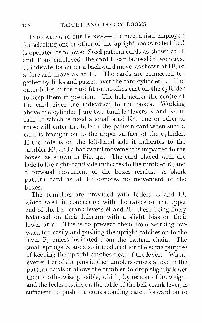
152 TAPPET AND DOBBY LOOMS
Indicating to the Boxes.—The mechanism employed
for selecting one or other of the upright hooks to be lifted
is operated as follows: Steel pattern cards as shown at Hand H" are employed : the card H can be used in two ways,
to indicate for either a backward move, as shown at H^, or
a forward move as at H. The cards are connected to-
gether by links and passed over the card cylinder J . The
outer holes in the card fit on notches cast on the cylinder
to keep them in position. The hole nearer the centie of
the card gives the indication to the boxes. Working
above the cylinder J are two tumbler levers K and K^, in
each of which is fixed a smah stud K-; one or other of
these will enter the hole in the pattern card when such a
card is brought on to the upper surface of the cylinder.
If the hole is on the left-hand side it indicates to the
tumbler K^, and a backward movement is imparted to the
boxes, as shown in Fig. 44. The card placed with the
hole to the right-hand side indicates to the tumbler K, and
a forward movement of the boxes results. A blank
pattern card as at H- denotes no movement of the
boxes.
The tumblers are provided with feelers L and L^,
which work in connection with the tables on the upper
end of the bell-crank levers M and M^, these being finely
balanced on their fulcrum with a slight bias on their
lower arm. This is to prevent them from working for-
ward too easily and pushing the upright catches on to the
lever F, unless indicated from the pattern chain. The
small springs X are also introduced for the same purpose
of keeping the upright catches clear of the lever. When-ever either of the pins in the tumblers enters a hole in the
pattern cards it allows the tumbler to drop slightly lower
than is otherwise possible, which, by reason of its weight
and the feeler resting on the table of the bell-crank lever, is
sufficient to push iLe corresponding catch forward on to
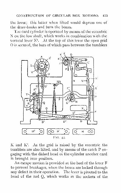
CONSTRUCTION OF CIRCULAR BOX MOTIONS 153
the lever; this latter when lifted would depress one of
the draw-hooks and turn the boxes.
The card cylinder is operated by means of the eccentric
N on the low shaft, which works in combination with the
vertical lever N^ At the top of this lever the open grid
O is secured, the bars of which pass between the tumblers
OO H'—S
O O OOFig. 44.
K and K^ As the grid is raised by the eccentric the
tumblers are also lifted, and by means of the catch P en-
gaging with the dished head of the cylinder another card
is brought into position.
An escape motion is provided at the heel of the lever Fto prevent breakages, when the boxes are locked throughany defect in their operation. The lever is pivoted to the
head of the rod Q, which works in the sockets of the
154 TAPPET AND DOBBY LOOMS
bracket R. The spring S exerts sufficient pressure on the
curved lever T, which under normal conditions prevents
the lever F from rising at the heel when the boxes are
being turned. If, however, any obstruction should pre-
vent the boxes from rotating, and the lever from rising
at the upright catches, it would lift at the heel by over-
coming the tension of the spring, which would draw the
lever back into position immediately the eccentric Gturns away from the pulley F\
A spring hammer U, working in contact with the disc
V, is provided to steady the action of the boxes, and re-
duce the vibration when turning.
Circular Skip-box Motion.—The mechanism em-ployed in this type of box motion varies slightly in con-
struction from that already described and illustrated in
Fig. 44. The general arrangement of the various parts is
practically the same, but the chief points of difference
may be stated as follows : Compared with the mechanism
shown in Fig. 44, a spur-wheel is fixed on the box spindle
to take the place of the pegged disc B\ The draw-hooks
C and C^ are substituted by a duplex rack, the respective
sides of which are made to engage with the spur-wheel as
required. The two sides of the rack merge into one lever,
which is pivoted at the bottom to a cross-lever similar to
D and D^ The nature of the movement imparted to the
rack is twofold, (a) It is free to move laterally to allow
of either side being put into gear with the spur-wheel,
according to the direction in which it is desired to turn the
boxes, {b) In order to turn the boxes, the rack must be
drawn downwards. The rack is operated in exactly the
same way as the draw-hooks, with this point of differ-
ence: the distance moved or the stroke imparted to the
rack can be varied in order to turn the boxes one, two or
three forward or backward. This is obtained by the
method of attaching the upright catches E and E' to the
FEATURES OF CIRCULAR BOX MOTIONS 155
single cross-lever. The catches are not pivoted directly
on to the end of this lever, but are first compounded with
a short lever, which is attached to the cross-lever in such
proportions of leverage that to raise one of the upright
catches the rack is drawn down such a distance as to turn
the boxes one forward or backward. With the alternate
catch lifted, the stroke of the rack is doubled, and so two
boxes are turned. Should both catches be indicated to be
raised at the same time, then three boxes would be turned.
Additional mechanism is necessary to put the rack in gear
with one or the other side of the spur-wheel.
It will be observed that this type of box motion affords
greater scope for weaving fancy wefting plans, as any
box of the set can be brought level with the race irre-
spective of its position in relation to the preceding shuttle.
The Working of Circular Box Motions.—Gener-
ally speaking, circular box mechanism demands moreattention on the part of the tuner than box motions of the
rising or drop-box class. This is primarily due to the in-
creased speed at which the looms provided with the
former class of box motion are run in comparison with
looms provided with a box motion of the latter class.
The mechanism in the circular box type is also moredelicate in construction, and consequently more sensitive
to any slight irregularity or failure of the working parts.
The setting of the boxes is very important to ensure satis-
factory working. They should be set in perfect align-
ment with the shuttle race and the reed. The boxes
must also work squarely with the going part, by setting
the additional connecting arm which couples the outer
end of the boxes to the stud in the balance-wheel in per-
fect truth with the crank-arms, in order to keep the lateral
movement of the boxes and going part in unison. Defec-
tive setting is a common cause of the shuttle flying out,
as well as the boxes not working smoothly, as the shuttle
156 TAPPET AND DOBBY LOOMS
is thrown out when leaving the box, and not being pro-
perly checked when entering, by reason of its bearing
heavily against the box side, the boxes cannot turn freely
on account of the shuttle or picker impeding their move-
ment.
Timing the boxes is of equal importance to the setting.
They should be timed so that they are not less than half-
way turned when the crank is on the front centre and the
reed beating up the weft. Any deviation from this
general rule must only be effected in combination with
any necessary alteration in the method of timing the
picking and the shedding motions for reasons previously
stated. When the boxes are timed to change with the
going part in this position, the picker is or should be
quite clear of the shuttle tip, and so allows them to turn
freely in either direction. Any defect in this particular
will be a productive source of trouble, and is one which is
a very common cause of unsatisfactory working. The re-
peated contact of the shuttle with the picker soon wears
a hole into the latter, so that if the shuttle when in the
box is in close contact with the picker, before the boxes
can turn the shuttle must be forced slightly forward into
the box, in order to be in a favourable position for receiv-
ing the pick; this is done by the sheer force of the box
motion overcoming the tension exerted on the shuttle in
the box. If the shuttle fits the box fairly tightly it is pre-
vented from sliding forward readily, with the result that
the boxes cannot turn freely, and consequently they do
not complete their movement for the pick to take place.
As a result the shuttle is either thrown out or only sent
part way across the race, and is trapped in the shed.
Occasionally the boxes only become half-way turned;
then the picker comes in contact with the end of the
shuttle-box, and the loom is stopped or the picking arm
or picking strap is broken. With reference to the above
SETTING AND TIMING 157
remarks, the strength of the pick when driving the shuttle
into the box has a decided influence. The force of the
pick should not be too excessive, but should be regulated
to drive the shuttle across the race into the box, but not
to jamb the picker full up to the end of the picker spindle,
or the defect referred to will be accentuated
—
i.e., the
shuttle tip will be in close contact with the picker, and the
shuttle must be pushed forward before the boxes can turn.
Another important feature is thechecking of the shuttle.
The length of the check should be adjusted to the strength
of the pick in such proportions that the shuttle will
be checked with the tip clear of the picker; not with the
picker driven back to its extreme position on the spindle.
The relation of the shuttle to the picker must be such as
to allow the latter to move slightly backward under the
least possible pressure from the tip of the shuttle, so that
the movement of the boxes will not be interrupted whenbringing another shuttle into position. The manner in
which the shuttles fit the respective boxes may easily act
adversely to their movement. In the ordinary circular
box loom the action of the draw-hooks may affect the
timing of the boxes. The draw-hooks should be ad-
justed for length and position, so that no matter which
hook is in action the boxes will be turned with the going
part in the same position. In this type of box motion
the boxes are under no positive control during such time
as they are being turned. The draw-hooks pull them
round up to a given point, then immediately the projec-
tion on the disc, which works in contact with the spring
hammer, has passed the highest point, the boxes movequickly forward in advance of the draw-hook, by reason
of the pressure of the spring hammer. This may have a
detrimental effect on the working by reason of the vibra-
tion which takes place if the tension of the spring is
excessive.
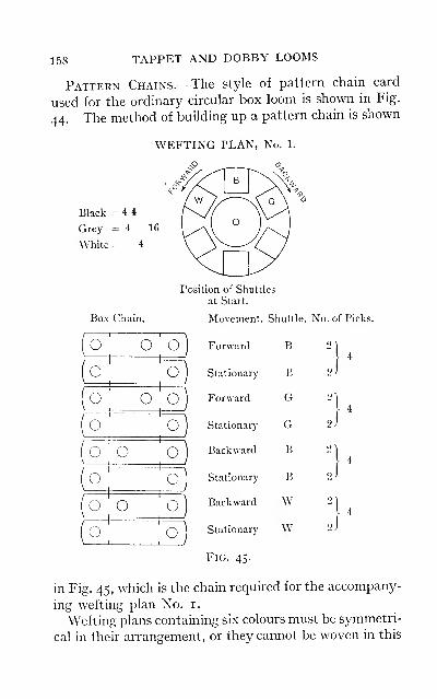
158 TAPPET AND DOBBY LOOMS
Pattern Chains.—The style of pattern chain card
used for the ordinary circular box loom is shown in Fig.
44. The method of building up a pattern chain is shown

CHAIN-MAKING FOR CIRCULAR BOXES 159
type of loom
—
i.e., the shuttle carrying the colour next
required must be one forward or backward of the box
WEFTING PLAN, No. 2
A= 24 24B= 4C= 4
D= 24 2 2 24
E= 2 2 2 2
F= 2
24
^
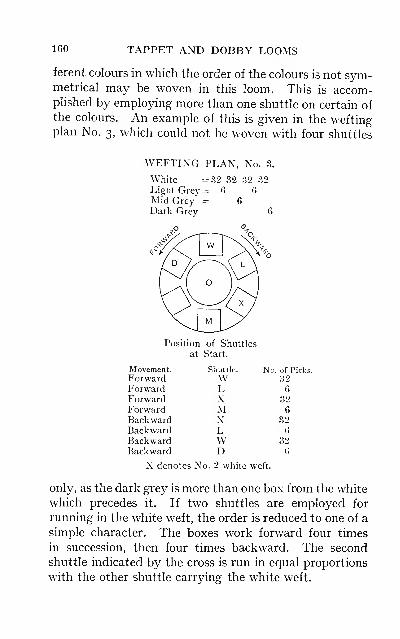
160 TAPPET AND DOBBY LOOMS
ferent colours in which the order of the colours is not sym-metrical may be woven in this loom. This is accom-plished by employing more than one shuttle on certain ofthe colours. An example of this is given in the weftingplan No. 3, which could not be woven with four shuttles
WEFTING PLAN, No. 3.
White ^32 32 32 32Light Grey = 6 6
Mid Grey' = 6Dark Grey = 6
Position
CHAPTER VII
LET-OFF MECHANISM
These motions are employed for regulating the amountof warp delivered from the warp beam, and also to main-
tain the necessary tension on the warp during the time that
shedding and beating-up take place. The let-off motion
has a direct influence on the number of picks per inch put
in the cloth, being subsidiary to the take-up motion. There
are two common classes of let-off motions, each class con-
taining different types, the principle involved and the
construction of each type in the two classes being practi-
cally the same. These motions are classified either as
negative or as positive let-offs. The former term is
theoretically correct, but is practically a misnomer, since
the construction of this class of motion is such that it is
solely employed for the purpose of keeping the warp in
tension, and it does not in any definite manner let off the
warp, the latter being drawn from the warp beam as re-
quired. Motions classed as " positive " differ from the
former in that the warp beam is actuated mechanically in
order to let off the requisite amount of warp, the motions
being automatic in their action. These motions, how-ever, do not necessarily give off exactly the same length
of warp for each pick, but are so constructed that they
are sensitive to variations in the tension on the warp,
which is brought about by any cause
—
e.g., the difference
in the counts of the weft yarns, as when weaving fancy
L i6i
162 TAPPET AND DOBBY LOOMS
vesting fabrics spotted by means of extra silk weft or
other yarns of much finer counts than those used for the
ground.
Various attempts have been made to construct a
positive let-off the principle of which was to draw the
warp off the beam by means of drawing rollers. The
rollers were driven by a train of wheels in a manner
similar to a positive take-up motion, suitable provision
being made for regulating the let-off of the warp to the
take-up of the piece in correct relation to each other, as
occasioned by the variation in the shrinkage of the differ-
ent weave structures, counts and quality of yarns, and in
the number of picks per inch in different cloths. It is
chiefly on account of these varying factors, and of the
difficulty experienced in taking back the exact amount of
warp after picking out, and at the same time preventing
a shady place in the cloth, that this class of motion has
not been adopted.
A let-off motion should possess the following features
:
Uniform tension should be maintained on the warp
during the cycle of motions attendant on each revolution
of the crankshaft. Provision should be made for re-
gulating the motion necessitated by reason of the de-
creasing diameter of the warp on the beam, from the
commencement to the finish of the warp. It should pro-
vide a ready means for taking back the warp on to the
beam after unweaving for any defect. The motion
should be sensitive, and readily respond to any variation
in the tension of the warp.
Negative Let-off Motions.—These are referred to
in different terms—namely, brake, friction and twitch
rope let-off. The principle is the same in each, the dif-
ference being in the method of application. The warp
beam is supplied with suitable ruffles, one at each end,
to which a brake may be applied, usually a steel band
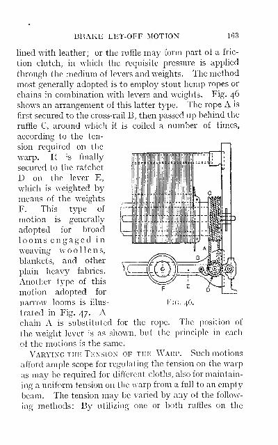
BRAKE LET-OFF MOTION 163
lined with leather; or the ruffle may form part of a fric-
tion clutch, in which the requisite pressure is applied
through the medium of levers and weights. The method
most generally adopted is to employ stout hemp ropes or
chains in combination with levers and weights. Fig. 46
shows an arrangement of this latter type. The rope A is
first secured to the cross-rail B, then passed up behind the
ruffle C, around which it is coiled a number of times,
according to the ten-
sion required on the
warp. It is finally
secured to the ratchet
D on the lever E,
which is weighted bymeans of the weights
F. This type of
motion is generally
adopted for broad
looms engaged in
weaving woollens,blankets, and other
plain heavy fabrics.
Another type of this
motion adopted for
narrow looms is illus-
trated in Fig. 47. Achain A is substituted for the rope. The position of
the weight lever is as shown, but the principle in each
of the motions is the same.
Varying the Tension of the Warp.—Such motions
afford ample scope for regulating the tension on the warp
as may be required for different cloths, also for maintain-
ing a uniform tension on the warp from a full to an empty
beam. The tension may be varied by any of the follow-
ing methods: By utilizing one or both ruffles on the
Fig. 46.
164 TAPPET AND DOBBY LOOMS
beam; increasing the number of coils on the ruffles;
adjusting the position of the weight on the lever; or
by means of additional weights. In the looms em-
ployed for weaving the heavier class of fabrics, two back
rails are employed at the back rest, the warp being inter-
laced as shown in Fig. 47. This is a very useful arrange-
ment, as the tension due to interlacing the warp in this
manner reduces very considerably the friction to be
applied by means of the ropes or chains on the ruffles;
this also renders the motion more sensitive to the varying
strains on the warp. There is a limit, however, to which
additional coils can be made effective; if the ropes are
coiled too frequently around the ruffles, and excessive
weight placed on the levers, the delivery of the warp will
be very irregular. This is due to the ropes maintaining
their grip on the ruffles without allowing the warp beamto slip forward; consequently the weight lever is gradu-
ally raised and the rope is slackened between the beamand the cross-rail, until the friction between the coils
and the ruffle is no longer sufficient to keep the warp beamin check ; the beam then moves quickly forward, deliver-
ing an indefinite length of warp, which allows the levers to
drop and the ropes to regain their grip. This process is
repeated again and again, with the result that the
numbers of picks per inch are irregular, and the piece is
very shady weft way. For this reason it will be found
that equal friction applied on each ruffle yields better
results than having excessive tension on one and the
other only lightly tensioned.
Causes of Defective Working.—The above feat-
ures outline the chief defect in this class of let-off motion,
which is in the main the cause of dark and light places in
the cloth. This defect may also be traced to the ropes
becoming dirty and greasy through usage. Owing to the
tension exerted on the ropes they are speedily drawn and
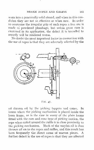
BRAKE ROPES AND CHAINS 165
worn into a practically solid strand, and when in this con-
dition they are not so effective as when new. In order
to overcome the irregular grip of such ropes a free use is
made of powdered plumbago, but unless great care is
exercised in its application, the defect it is intended to
remedy will be rendered worse.
No doubt the most important factor in connection with
the use of ropes is that they are adversely affected by the
Fig. 47.
oil thrown off by the picking tappets and cones. In
looms where the picking mechanism is placed inside the
loom frame, as is the case in many of the plain looms
fitted with the cam and cone type of picking motion, the
rope when coiled around the ruffle is in close proximity to
the picking mechanism. Much of the surplus oil is thus
thrown off on to the ropes and ruffles, and this result has
been frequently the direct cause of uneven pieces. Afurther defect in the use of ropes is that they are affected
166 TAPPET AND DOBBY LOOMS
by changes in the temperature of the weaving shed, such
changes increasing or diminishing their grip on the beamand resulting in the irregular delivery of the warp be-
tween one portion of the piece and another.
It is with the object of overcoming this defect that
chains have been substituted for hemp ropes, as they are
not affected by any change in the humidity. There is
one feature in the use of chains which is worthy of special
consideration. Some tuners prefer to use chains without
applying any oil or other lubricant, as they claim that a
very regular grip can be maintained between the chain
and the ruffle, providing that the latter is turned up true
and smooth. No doubt this practice is permissible, but
the difficulty is in keeping them perfectly dry throughout.
They are not only liable to receive the surplus oil thrown
off by the picking or any other mechanism of the loom,
but the indiscriminate weaver will often apply oil with the
object of increasing the production. For this reason it
is much safer to lubricate the chain and ruffle, with either
tallow or vaseline, at the commencement of a new warp,
and so mitigate the possibility of surplus oil falling on
them during weaving. A defect more common in light
wefted fabrics is due to uneven shedding by reason of one
or more of the heald shafts being lifted too high or drawntoo low. An irregular lift of the healds in the formation
of the shed is often sufficient to cause the warp to be
jerked forward, as the warp beam is only lightly tensioned,
the defect being more in the nature of a crack or incision
across the piece than one of shadiness.
Advantages and Disadvantages of this Class of
Motion.—The advantages of this class of let-off motion
are to be found in the simplicity of their construction;
their suitability for light and medium weighted cloths;
their adaptability for weaving tender warps and those
made from yarns possessing few elastic properties. This
DEFECTS OF THIS MOTION 167
latter is made possible on account of the oscillatory
movement which is imparted to the warp, simultaneously
with the strain of shedding and beating-up. Occasion-
ally for this purpose the back rest is so constructed as to
vibrate and yield to these varying strains, the oscillation
being obtained by means of a swinging back rest, operated
by a suitable lever actuated by a cam fixed on the crank-
shaft. The disadvantages may be summarized as
follows: Expenses incurred in the renewal of ropes;
the difficulty experienced by the weaver when taking
back the warp on to the beam after picking out, and also
of regulating the tension on the warp in order to start
up without showing a shady place in the piece; and
the amount of attention demanded from the tuner or
weaver to adjust the weight as required by the de-
creasing diameter of the warp on the beam.
The last of these factors is a constant source of defec-
tive pieces. The grip on the ruffles must be gradually
diminished, in relation to the decreasing leverage which
the warp line possesses at various stages. This is further
explained by reference to Fig. 47, in which the lines 3, 2, i
represent the position of the warp line at the start of each
cut in a three-cut warp. The leverage from the centre of
the beam to the point 4 is loin. ; this leverage at the end
of the first cut is reduced to 8|in., and at the end of the
second cut to 6|in. From these approximate figures it
will be evident that if the force of the beat-up and the
strain due to shedding are equal throughout the warp,
the beam will be drawn round much more easily at the
commencement, or during the first cut, with a leverage
of from 10 to 8| in., than during the last cut, with a lever-
age of from 6| to 3in., which is the radius of the beam. De-fects due to the above are most prevalent when weavingfabrics containing a few number of picks per inch, and are
always accentuated in the last cut off the warp. From
168 TAPPET AND DOBBY LOOMS
observations made it was found that many of the pieces
defective in this particular were the last cut off the beam.
This is readily explained when it is remembered that the
decrease in the diameter of the warp changes much morequickly during the last cut than during the first, the pro-
portion being as 3 to i. In such defective pieces the
worst examples of these defects were found to be morenoticeable in the last 10 to 15yds. of the piece. For this
particular class of fabrics it is an advantage to use cased
beams, say with a diameter of 8in., in preference to solid
beams of about 6in. diameter, as there would not be such
a marked difference in the changing diameter during the
last cut off the beam.
Positive Let-off Motions.—The construction of the
different types of these motions varies only in matters of
detail. The principal features involved are the sensitive
back-rest over which the warp is passed, and the methodof operating the let-off shaft.
The construction of a type of positive let-off motion is
illustrated in Fig. 48. The worm-wheel A fixed to the
warp beam is made to gear with the worm B on the let-
off shaft C. This shaft is supported in suitable brackets
fixed to the loom frame, usually on the inside, the back
bracket shown at D being made in cup form for the pur-
pose of retaining a quantity of oil, in which the wormrotates. On the shaft C a ratchet wheel E is secured, the
ratchet being actuated by means of the catches F and F^,
which are supported in the catch-box G fulcrumed on the
let-off shaft. The catches are made of different lengths,
the catch F being half the pitch of the teeth in the ratchet
wheel longer than F^. This provision renders the motion
more sensitive to any variation in the tension applied to
the warp. The shaft C is prevented from turning too
freely by means of a brake strap acting on the brake
wheel H. The catches are operated from the crankshaft
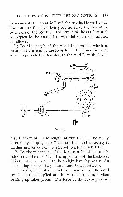
FEATURES OF POSITIVE LET-OFF MOTIONS 169
by means of the eccentric J and the cranked lever K, the
lower arm of this lever being connected to the catch-box
by means of the rod K^ The stroke of the catches, and
consequently the amount of warp let off, is determined
as follows:
(a) By the length of the regulating rod L, which is
secured at one end of the lever K, and at the other end,
which is provided with a slot, to the stud L^ in the back-
P^,pi
Fig. 48.
rest bracket M. The length of the rod can be easily
altered by slipping it off the stud L^ and screwing it
farther into or out of the screw-threaded bracket L^.
(b) By the movement of the back-rest M, which has its
fulcrum on the stud M\ The upper arm of the back-rest
M is suitably connected to the weight lever by means of a
connecting rod at the points N and O respectively.
The movement of the back-rest bracket is influenced
by the tension applied on the warp at the time whenbeating-up takes place. The force of the beat-up draws
170 TAPPET AND DOBBY LOOMS
the warp in the direction indicated at P, and simultane-
ously causes the back-rest to move inwards; this allows
the rod L to work forward, and the lever K and the catch-
box to fall, with the result that the catches engage with
the teeth of the ratchet wheel at a lower point than would
be possible if there was no movement of the back-rest.
It should be noticed that the cam J on the crankshaft is
so fixed that the throw
—
i.e., the swell of the cam
—
has worked clear of the lever K when beating-up is taking
place, and therefore permits the lever and the catches to
drop to the full extent, as determined by the movementof the back-rest. It will be obvious that any weight on
the weight lever will result in great resistance to the
movement of the back-rest, and consequently will increase
the impact during beating-up of the weft, and vice versa
with a reduced weight on the lever at O. The successful
working of this class of motion depends on maintaining a
correct relation between the stroke of the lever K and
the movement of the back-rest M, as the requisite amountof warp may be let off with more or less movement of the
back-rest. If the stroke given to the lever K from the
cam J is not sufficient to rotate the ratchet wheel and let
off the necessary amount of warp, the tension on the warpwill quickly increase, drawing forward the back-rest and
lifting the weight lever, thereby increasing the stroke of
the lever K, so that the catches take more teeth of the
ratchet wheel. To avoid this the motion should be regu-
lated by means of the rod L, which must be lengthened
in order to give a greater stroke to the lever K with less
movement of the back-rest. On the other hand, this
should not be carried to the extreme until very little
movement of the back-rest is perceptible. The best
results are obtained when the motion is set so that the
weight lever rises and fahs regularly at the beat-up.
When the proper relation has once been obtained, the
REGULATING THE MOTION 171
motion will yield very satisfactory results, as any ten-
dency for the warp to increase in tension is indicated
through the sensitive back-rest to the lever K, whilst any
slackening in the tension is taken up by reason of the
weight lever drawing down the rod N, and moving the
back-rest and the stud L' to their backward position,
which shortens the stroke of the lever K and reduces the
amount of warp let off.
This particular feature might appear to be a rather
defective arrangement—namely, that the regulation is
obtained after the tightening or slackening of the warp
has taken place. With careful setting at the commence-
ment of a warp the motion can be made very sensitive
and to respond to any slight variation in the tension,
therefore immediately correcting its action before any
defect is produced in the woven fabric.
Regulating this Class of Motion.—It must not be
inferred from the foregoing remark that no regulating of
the motion is necessary from the commencement to the
finish of a warp. The writer has, however, had experi-
ences with warps of very fine counts, one and two cuts in
length, which have been woven without the motion rod
or the weight on the lever requiring any adjustment
throughout the warp. There are two factors which have
a direct influence on the amount of attention necessary to
keep this class of motion working uniformly throughout
the warp. The first is the alteration in the diameter of
the warp from a full to an empty beam, and secondly,
the alteration in the direction of the resultant of the forces
P and P^ when the beam is full, to the resultant of the
forces P and P- when the beam is nearly empty.
Obviously the warp beam must travel quicker as the
diameter decreases in order to let off the same amount of
warp. This, as already explained, should be effected by
regulating at the motion rod L, giving a greater traverse
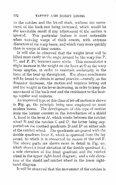
172 TAPPET AND DOBBY LOOMS
to the catches and the let-off shaft, without the move-ment of the back-rest bemg increased, which would be
the inevitable result if any adjustment of the motion is
ignored. This particular feature is most noticeable
when weaving warps of thick counts, with extreme
diameters of the warp beam, and which vary more quickly
than in warps of finer counts.
It will also be observed that the weight lever will be
lifted more easily as the angle formed by the warp line P,
F\ and P, P-, becomes more acute. This necessitates a
slight increase in the weight on the lever at O as the warpbeam empties, in order to maintain uniformity in the
force of the beat-up throughout. The above conclusions
will be found to obtain in actual practice—namely, as the
diameter decreases, the motion rod requires letting out
and the weight in the lever increasing, in order to keep the
movement of the back-rest and the resistance to the beat-
up regular and uniform.
An improved type of this class of let-off motion is shownin Fig. 49, the principle being now employed on mostmodern looms. The development of this type of motion
from the former consists in the introduction of a shield
A, fixed to the lever A\ which works between the ratchet
wheel B and the catches C and C\ the latter being sup-
ported on the toothed quadrants D and D^ on either side
of the ratchet wheel. The quadrants are geared with the
double quadrant lever E, which is operated from the lay
sword, to which it is connected by means of the rod F.
The above parts are shown more in detail in Fig. 50;
which shows a front elevation of the double quadrant E;a side elevation of the front quadrant and the ratchet
wheel in the upper right-hand diagram ; and a side eleva-
tion of the shield and ratchet wheel in the lower right-
hand diagram.
It will be observed that the movement of the catches is
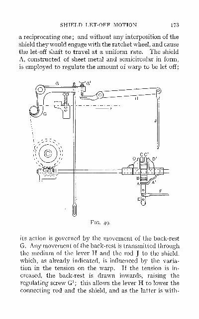
SHIELD LET-OFF MOTION 173
a reciprocating one ; and without any interposition of the
shield they would engage with the ratchet wheel, and cause
the let-off shaft to travel at a uniform rate. The shield
A, constructed of sheet metal and semicircular in form,
is employed to regulate the amount of warp to be let off;
Fig. 49.
its action is governed by the movement of the back-rest
G. Any movement of the back-rest is transmitted through
the medium of the lever H and the rod J to the shield,
which, as already indicated, is influenced by the varia-
tion in the tension on the warp. If the tension is in-
creased, the back-rest is drawn inwards, raising the
regulating screw G^ ; this allows the lever H to lower the
connecting rod and the shield, and as the latter is with-
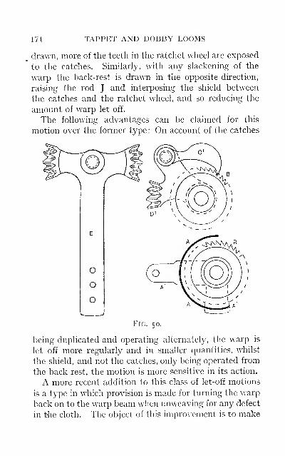
174 TAPPET AND DOBBY LOOMS
drawn, more of the teeth in the ratchet wheel are exposed
to the catches. Similarly, with any slackening of the
warp the back-rest is drawn in the opposite direction,
raising the rod J and interposing the shield between
the catches and the ratchet wheel, and so reducing the
amount of warp let off.
The following advantages can be claimed for this
motion over the former type : On account of the catches
being duplicated and operating alternately, the warp is
let off more regularly and in smaller quantities, whilst
the shield, and not the catches, only being operated from
the back-rest, the motion is more sensitive in its action.
A more recent addition to this class of let-off motions
is a type in which provision is made for turning the warp
back on to the warp beam when unweaving for any defect
in t4ie cloth. The object of this improvement is to make
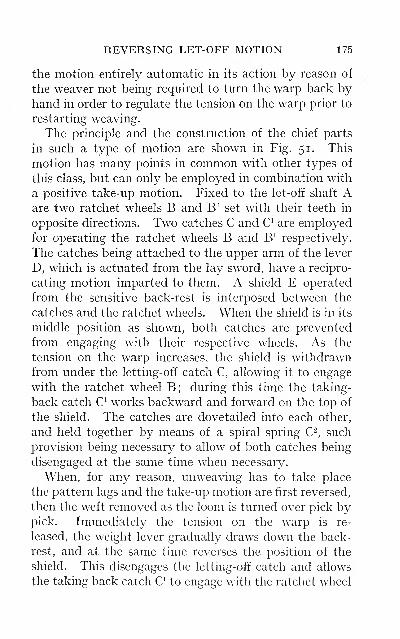
REVERSING LET-OFF MOTION 175
the motion entirely automatic in its action by reason of
the weaver not being required to turn the warp back byhand in order to regulate the tension on the warp prior to
restarting weaving.
The principle and the construction of the chief parts
in such a type of motion are shown in Fig. 51. This
motion has many points in common with other types of
this class, but can only be employed in combination with
a positive take-up motion. Fixed to the let-off shaft Aare two ratchet wheels B and B^ set with their teeth in
opposite directions. Two catches C and C^ are employed
for operating the ratchet wheels B and B^ respectively.
The catches being attached to the upper arm of the lever
D, which is actuated from the lay sword, have a recipro-
cating motion imparted to them. A shield E operated
from the sensitive back-rest is interposed between the
catches and the ratchet wheels. When the shield is in its
middle position as shown, both catches are prevented
from engaging with their respective wheels. As the
tension on the warp increases, the shield is withdrawnfrom under the letting-off catch C, allowing it to engage
with the ratchet wheel B; during this time the taking-
back catch C^ works backward and forward on the top of
the shield. The catches are dovetailed into each other,
and held together by means of a spiral spring C-, such
provision being necessary to allow of both catches being
disengaged at the same time when necessary.
When, for any reason, unweaving has to take place
the pattern lags and the take-up motion are first reversed,
then the weft removed as the loom is turned over pick bypick. Immediately the tension on the warp is re-
leased, the weight lever gradually draws down the back-
rest, and at the same time reverses the position of the
shield. This disengages the letting-off catch and allows
the taking back catch O to engage with the ratchet wheel
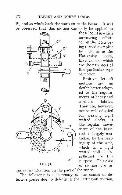
176 TAPPET AND DOBBY LOOMS
B\ and so winds back the warp on to the beam. It will
be observed that this motion can only be applied to
those looms in which
unweaving is effect-
ed by the loom be-
ing turned over pick
by pick, as in the
Hattersley loom,
the makers of which
are the patentees of
this particular type
of motion.
Positive let - off
motions are no
doubt better adapt-
ed to the require-
ments of heavy and
medium fabrics.
They are, however,
not so well adapted
for weaving light
wefted cloths, as
the regular move-
ment of the back-
rest is largely con-
trolled by the beat-
ing-up of the weft,
which in a light
wefted cloth is in-
sufficient for this
purpose. This class
of motion also re-
quires less attention on the part of the tuner.
The following is a summary of the causes of de-
fective pieces due to defects in the letting-off motion,
SUMMARY OF DEFECTS 177
the remedies for which are obvious: The beam wheel
springing out of gear with the worm; the beam wheel
and worm short of oil; defective brake strap due to
the presence of grease or dirt; irregular movement of
the back-rest; the catches missing when they are worndown or the teeth in the ratchet wheel worn down or
broken; strained warp beam shaft; and tampering with
the motion on the part of the weaver.

CHAPTER VIII
TAKE-UP MECHANISM
The function of a take-up motion is to draw the cloth
forward as it is w^oven. The operation is performed bymeans of a taking-up roller actuated by suitable mechan-
ism in such a manner that the cloth is drawn forward
regularly. The various types of these motions may be
divided into two classes—namely, negative and positive.
In the former class the principal feature is the methodby which motion is imparted to the taking-up roller, the
amount of cloth drawn forward at each pick being deter-
mined by the force applied by the reed to the fell of the
cloth at the beat-up. It is only as the cloth is pushed
forward by the reed that it is possible for the motion to
register any take-up. In the latter class the taking-up
roller is driven in a positive manner by a suitable train of
wheels actuated from some convenient part of the loom,
so that the same length of warp is drawn forward for each
pick of weft inserted.
Another feature of difference in the construction of the
two classes of motions is as follows: In the negative
motions only one taking-up roller or cloth beam is
employed, which performs the double function of drawing
the cloth forward as it is woven, and at the same time
winding it on to itself. In the positive motions there are
two rollers—the taking-up roller, which is employed solely
for drawing the cloth forward, and the cloth beam on to
which the cloth is wound.
178
NEGATIVE TAKE-UP MOTION 179
Negative Motions.—The constniction of a type of
this class of motion is illustrated in Fig. 52. To the
shaft of the cloth beam A the spur-wheel B is secured,
the latter being geared with the pinion wheel C which is
compounded with the ratchet wheel D. The latter is
actuated by the pawl E, which is attached to the upper
arm of the three-armed lever F fulcrumed at F'. Motion
is imparted to the lever F in one direction by means of
the stud G which is fixed in the lay sword. A forward
movement of the lever and pawl is obtained by reason of
the weight H on the arm of the lever F overcoming the
tension or pull of the piece at the time when the reed Jis beating up the weft. The retaining catches K are
necessary in order to prevent the motion from reversing
owing to the tension and pull of the piece being again
applied immediately the reed recedes from the fell of the
cloth. This type of motion is largely employed on plain
tappet looms weaving medium and heavy woollens andunion fabrics, for which it is specially adapted on account
of the quick movement which may be imparted to the
cloth beam when weaving fabrics containing few picks per
inch. This feature is made possible by reason of the move-
ment of the ratchet wheel being transmitted directly to
the cloth beam through the medium of the pinion wheel C.
Fig. 53 illustrates another type of negative motion
somewhat different in construction from that already
described. It is better adapted for weaving cloths con-
taining a large number of picks per inch, the ratio of the
first driver to the last follower being increased by the
introduction of an intermediate wheel and pinion. Thecloth beam A supported by the arbors A^ is provided with
a spur-wheel B which is in gear with the intermediate
pinion C. This pinion is secured to the shaft of the inter-
mediate wheel D, which in turn is geared with the ratchet
pinion E compounded with the ratchet wheel F. The
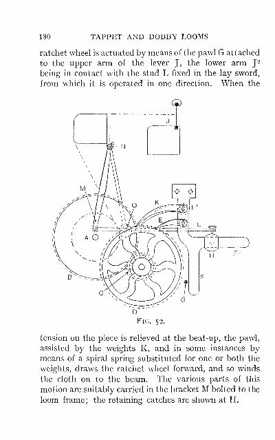
180 TAPPET AND DOBBY LOOMS
ratchet wheel is actuated by means of the pawl G attached
to the upper arm of the lever J, the lower arm J^
being in contact with the stud L fixed in the lay sword,
from which it is operated in one direction. When the
Fig. 52.
tension on the piece is relieved at the beat-up, the pawl,
assisted by the weights K, and in some instances bymeans of a spiral spring substituted for one or both the
weights, draws the ratchet wheel forward, and so winds
the cloth on to the beam. The various parts of this
motion are suitably carried in the bracket M bolted to the
loom frame ; the retaining catches are shown at H.
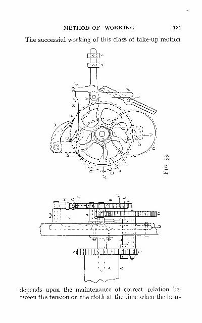
METHOD OF WORKING 181
The successful working of this class of take-up motion
E^iiiMmcEti
depends upon the maintenance of correct relation be-
tween the tension on the cloth at the time when the beat-
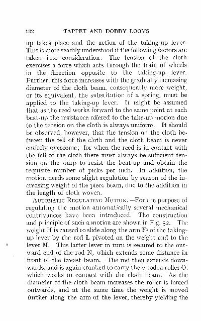
182 TAPPET AND DOBBY LOOMS
Up takes place and the action of the taking-up lever.
This is more readily understood if the following factors are
taken into consideration: The tension of the cloth
exercises a force which acts through the train of wheels
in the direction opposite to the taking-up lever.
Further, this force increases with the gradually increasing
diameter of the cloth beam, consequently more weight,
or its equivalent, the substitution of a spring, must be
applied to the taking-up lever. It might be assumed
that as the reed works forward to the same point at each
beat-up the resistance offered to the take-up motion due
to the tension on the cloth is always uniform. It should
be observed, however, that the tension on the cloth be-
tween the fell of the cloth and the cloth beam is never
entirely overcome; for when the reed is in contact with
the fell of the cloth there must always be sufficient ten-
sion on the warp to resist the beat-up and obtain the
requisite number of picks per inch. In addition, the
motion needs some slight regulation by reason of the in-
creasing weight of the piece beam, due to the addition in
the length of cloth woven.
Automatic Regulating Motion.—For the purpose of
regulating the motion automatically several mechanical
contrivances have been introduced. The construction
and principle of such a motion are shown in Fig. 52. The
weight H is caused to slide along the arm F- of the taking-
up lever by the rod L pivoted on the weight and to the
lever M. This latter lever in turn is secured to the out-
ward end of the rod N, which extends some distance in
front of the breast beam. The rod then extends down-
wards, and is again cranked to carry the wooden roller O,
which works in contact with the cloth beam. As the
diameter of the cloth beam increases the roller is forced
outwards, and at the same time the weight is movedfurther along the arm of the lever, thereby yielding the
UTILITY OF NEGATIVE TAKE-UP 183
increased power necessary to actuate the take - upmotion.
Wlien the relation between the tension of the cloth and
the weight is once obtained, any shght discrepancy in the
take-up is quickly corrected. If the motion is not setting
up quickly enough the reed comes in contact with the fell
of the cloth sooner, and the tension is relieved to a greater
extent, this being attended by a corresponding increase
in the take-up. Similarly, any excess of setting up would
correct itself by reason of the beat-up decreasing in force,
and the slackening of the piece not being sufficient to
allow any take-up to be registered until the tension again
became normal.
Features of Negative Motions.—This class of
motion is most advantageously employed for heavily
wefted goods. These are liable to slip on the friction
roller of a positive take-up motion, and are therefore
better w^oven with a negative motion, where the piece is
wound direct on to the cloth beam. It is also preferable
for weaving cloths in which the weft yarns are of dif-
ferent counts, also in fancy vestings and similar fabrics
in which the picks per inch vary on account of the extra
silk spotting picks. This class of motion is unsuitable
for weaving lightly wefted goods in which the reed is not
required to beat up the picks, but merely to push theminto position with the preceding picks. In the absence
of the beat-up the motion requires more attention
from the weaver if the picks per inch are to be kept
uniform. Frequent measurement of the picks should be
made, as under the above conditions the motion mayvary the number of picks inserted per inch very con-
siderably. The weaver should be warned against tam -
pering with the amount of weight on the taking-up lever,
as it is a very common practice for the weaver to keep a
supply of weights, consisting of parts of broken loom
184 TAPPET AND DOBBY LOOMS
castings, by means of which some alteration in the number
of picks per inch may be effected without in any wayregulating the let-off motion. The amount of weight on
the taking-up lever should always be attended to whenstarting a fresh piece. It is the practice, when one piece
follows another out of the same warp, to weave what is
called a " lapping-on " into the succeeding piece, usually
from two to three yards; the full piece is then pulled off
the beam, and the lapping-on length used to start again
for the new piece. Unless there is a reduction of the
weight on the taking-up lever to compensate for the re-
duced diameter of the cloth beam a reduction in the
number of picks per inch will inevitably take place. In
order to avoid this the tuner should make it a condition
for the weaver not to proceed with the next piece until
the weight has been regulated and the picks per inch have
been counted.
Positive Take-up Motions.—There are several well-
known types of this class of take-up motion, the principle
involved in each being practically the same. The con-
struction of the various types only differs in minor de-
tails, the method of imparting motion to the train of
wheels employed for driving the take-up roller being the
chief point of difference. Some motions are driven inter-
mittently by means of a pawl and ratchet wheel; others
are driven continuously by means of a worm and worm-
wheel.
A type of an intermittent motion is illustrated in Fig.
54. The take-up roller A, frequently referred to as the
friction roller, feed roller, sand roller or the " gratter,"
is clothed with perforated sheet metal, which is woundround the roller with the rough side outward, for the
purpose of increasing the grip on the cloth to prevent
slipping. To the shaft of this roller a spur-wheel Bis secured, this being geared with the pinion wheel C
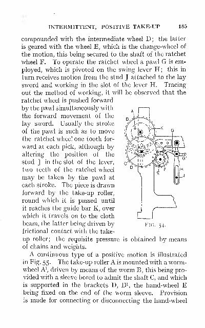
INTERMITTENT, POSITIVE TAKE-UP 185
compounded with the intermediate wheel D; the latter
is geared with the wheel E, which is the change-wheel of
the motion, this being secured to the shaft of the ratchet
wheel F. To operate the ratchet wheel a pawl G is em-
ployed, which is pivoted on the swing lever H; this in
turn receives motion from the stud J attached to the lay
sword and working in the slot of the lever H. Tracing
out the method of working, it will be observed that the
ratchet wheel is pushed forward
by the pawl simultaneously with
the forward movement of the
lay sword. Usually the stroke
of the pawl is such as to movethe ratchet wheel one tooth for-
ward at each pick, although byaltering the position of the
stud J in the slot of the lever,
two teeth of the ratchet wheel
may be taken by the pawl at
each stroke. The piece is drawnforward by the take-up roller,
round which it is passed until
it reaches the guide bar K, over
which it travels on to the cloth
beam, the latter being driven byfrictional contact with the take-
up roller; the requisite pressure is obtained by meansof chains and weights.
A continuous type of a positive motion is illustrated
in Fig. 55. The take-up roller A is mounted with a worm-wheel A', driven by means of the worm B, this being pro-
vided with a sleeve bored to admit the shaft C, and whichis supported in the brackets D, D^, the hand-wheel Ebeing fixed on the end of the worm sleeve. Provision
is made for connecting or disconnecting the hand-wheel
Fig. 54.
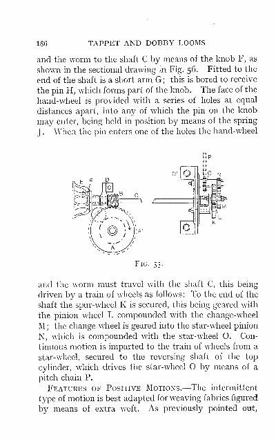
186 TAPPET AND DOBBY LOOMS
and the worm to the shaft C by means of the knob F, as
shown in the sectional drawing in Fig. 56. Fitted to the
end of the shaft is a short arm G; this is bored to receive
the pin H, which forms part of the knob. The face of the
hand-wheel is provided with a series of holes at equal
distances apart, into any of which the pin on the knob
may enter, being held in position by means of the spring
J. When the pin enters one of the holes the hand-wheel
Fig. 55-
and the worm must travel with the shaft C, this being
driven by a train of wheels as follows : To the end of the
shaft the spur-wheel K is secured, this being geared with
the pinion wheel L compounded with the change-wheel
M ; the change-wheel is geared into the star-wheel pinion
N, which is compounded with the star-wheel O. Con-
tinuous motion is imparted to the train of wheels from a
star-wheel, secured to the reversing shaft of the top
cylinder, which drives the star-wheel O by means of a
pitch chain P.
Features of Positive Motions.—The intermittent
type of motion is best adapted for weaving fabrics figured
by means of extra weft. As previously pointed out,
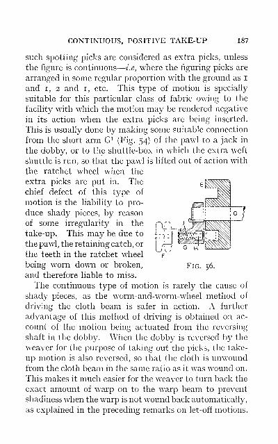
CONTINUOUS, POSITIVE TAKE-UP 187
such spotting picks are considered as extra picks, unless
the figure is continuous
—
i.e, where the figuring picks are
arranged in some regular proportion with the ground as i
and I, 2 and i, etc. This type of motion is specially
suitable for this particular class of fabric owing to the
facility with which the motion may be rendered negative
in its action when the extra picks are being inserted.
This is usually done by making some suitable connection
from the short arm G^ (Fig. 54) of the pawl to a jack in
the dobby, or to the shuttle-box in which the extra weft
shuttle is run, so that the pawl is lifted out of action with
the ratchet wheel when the
extra picks are put in. Thechief defect of this type of
motion is the liability to pro-
duce shady pieces, by reason
of some irregularity in the
take-up. This may be due to
the pawl, the retaining catch, or
the teeth in the ratchet wheel
being worn down or broken,
and therefore liable to miss.
The continuous type of motion is rarely the cause of
shady pieces, as the worm-and-worm-wheel method of
driving the cloth beam is safer in action. A further
advantage of this method of driving is obtained on ac-
count of the motion being actuated from the reversing
shaft in the dobby. When the dobby is reversed by the
weaver for the purpose of taking out the picks, the take-
up motion is also reversed, so that the cloth is unwoundfrom the cloth beam in the same ratio as it was wound on.
This makes it much easier for the weaver to turn back the
exact amount of warp on to the warp beam to prevent
shadiness when the warp is not wound back automatically,
as explained in the preceding remarks on let-off motions.
Fig. 56.
188 TAPPET AND DOBBY LOOMS
Some objections to the type of motion shown in Fig.
55 are as follows: The position of the taking-up roller in
relation to the piece is such that it acts on the face of the
piece, which in certain fabrics may be damaged. Theposition of the cloth beam in relation to the take-up roller
is also such that the back of the cloth cannot be seen
unless the piece is let slack for this purpose. It is an ad-
vantage, if not an essential, that the weaver should be
able to examine the back of the piece, and especially in
backed and double-cloth fabrics, as defects may be dis-
covered which would otherwise run throughout the piece.
It is worthy of note that the makers of this type of motion
have overcome the above defects by altering the position
of the take-up roller, which is now fixed immediately
under the breast beam, the direction of rotation being also
reversed.
Calculations for Take-up Motions.—For the pur-
pose of effecting any alteration in the number of picks
per inch, one of the wheels in the train is a change-wheel
;
this change-wheel may be either a driver or a driven
wheel. In the type of motion illustrated in Fig. 54 the
change-wheel E is a driver. Obviously any increase in
the number of teeth in this wheel will result in the follow-
ing wheels and the taking-up roller drawing the cloth
forward more quickly, with a corresponding reduction in
the picks per inch ; whilst the substitution of a wheel con-
taining a less number of teeth will increase the picks.
For the purpose of finding the number of teeth the
change-wheel must contain for a given number of picks
per inch, it is customary to supply the tuner with the
dividend number or gauge point of the motion. This is
obtained by the following formula
:
No. of teeth in No. of teeth in No. of teeth in
ratchet wheel F inter, wheel D roller wheel BNo. of teeth taken by No. of teeth in Circum. of the
X . ., , ,, X
the pawl G at each pick pinion wheel C roller A in inches
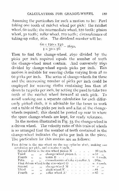
CALCULATIONS FOR CHANGE-WHEEL 189
Assuming the particulars for such a motion to be: Pawltaking one tooth of ratchet wheel per pick; the ratchet
wheel, 60 teeth; the intermediate wheel, 120 teeth; pinion
wheel, 30 teeth; roller wheel, no teeth; circumference of
taking-up roller, i6in. The dividend number will be:
60X120X110 r^-^ = 1650.I X 30 X 16
Then to find the change-wheel, 1650 divided by the
picks per inch required equals the number of teeth
the change-wheel must contain. And conversely 1650
divided by change-wheel equals picks per inch. This
motion is suitable for weaving cloths varying from 28 to
60 picks per inch. The series of change-wheels for these
and the intervening number of picks per inch could be
employed for weaving cloths containing less than 28
down to 14 picks per inch, by setting the pawl to take twoteeth of the ratchet wheel forward at each pick. Toavoid working out a separate calculation for each differ-
ently picked cloth, it is advisable for the tuner to workout a table of the picks per inch and a list of the change-
wheels required ; this should be posted up near to where
the spare change-wheels are kept, for ready reference.
In the motion illustrated in Fig. 55 the change-wheel is
a driven wheel. The velocity ratio of this train of wheels
is so arranged that the number of teeth contained in the
change-wheel indicates the picks per inch in the piece.
The particulars for this motion are as follows:
First driver is the star-wheel on the top cylinder shaft, making onerevolution per pick, and contains 8 teeth.
Second driver is ihe star-wheel pinion N .... =20 teeth.
Third ,, ,, change-wheel pinion I> . . . =18 ,,
Fourth ,, ,, worm B =1 tooth.
Fifth ,, ,, circumference of take-up roller A =20in.First driven wheel is the star-wheel O . . . . . =8 teeth.
Second ,, ,, change-wheel M = a: ,,
Third ,, ,, shaft-wheel K =84- ,.
Fourth ,, ,, roller wheel A^ =85 ,,
190 TAPPET AND DOBBY LOOMS
The working for the above may be stated as follows
:
Drivers= 8x20xl8xlx20x(;^ = picks per inch) _ 1 20 pDriven =8 x (a;= teeth in change-wheel) x 84 x 85 ~119a;
Therefore x, the number of teeth in the change-wheel,
equals f, the picks per inch, when a small percentage for
shrinkage in the piece is allowed, which takes place be-
tween the fell of the cloth and the taking-up roller; this
shrinkage will vary slightly in different cloths.
An advantage of this motion is, that a very wide range of
cloths can be woven from a small stock of change-wheels,
a large star-wheel containing i6 teeth being provided for
this purpose. This wheel may be substituted for the
star-wheel on the top cylinder shaft to act as a driver, or
be used in place of the star-wheel O as a driven wheel.
When the i6 wheel is employed as a driver, the change-
wheel indicates half the number of picks
—
i.e., a 40 wheel
would give 20 picks; when used as a driven wheel, a 40
change-wheel would give 80 picks. Assuming the highest
and lowest change-wheels of the series in stock to be 60
and 30 respectively, a range of cloths could be woven
containing as many as 120 picks with the 60 change-
wheel down to 15 picks with a 30 change-wheel.
CHAPTER IX
AUXILIARY MECHANISM
With the object of making the power-loom more auto-
matic in its action, various mechanisms have been intro-
duced, the chief of which are the weft stop-motion, warpprotector motion, warp stop-motions, and temples. In
addition various patents are being invented from time
to time the introduction of which makes the duties of the
tuner more exacting; needless to say, such additional
mechanism which does not justify its permanent adop-
tion is quickly discarded.
Weft Stop-motion.—The function of this motion is to
stop the loom when the weft supply fails or breaks. Sucha motion is practically indispensable on fast-running
looms engaged in weaving the more intricate and ex-
pensive fabrics. There are, however, many types of
plain looms employed for weaving low woollen and union
fabrics, on which weft stop-motions are not adopted.
There are two distinct types of these motions, knownas the " side weft fork " and the " centre weft fork." Atype of the former is illustrated in Fig. 57. The weft
fork A fulcrumed on the rod B is made with the hookedend slightly heavier than the forked end, which consists
of three prongs bent at right angles. The rod B is held
in position by the knob of the pistol lever C, this being
placed in close proximity to the starting lever D. Thehooked end of the fork works over the snecked surface of
the hammer lever E, the lower arm E^ extending down-
191
192 TAPPET AND DOBBY LOOMS
wards and projecting over the low shaft F. On this
shaft is fixed the cam G, which, making one revolution
every two picks, lifts the lever E^ and throws back the
upper arm E on alternate picks. Fixed in the shuttle
race at the entrance to the shuttle-box is a grid H, which
contains three apertures to admit the prongs of the fork
when the reed comes to its front position at the beat-up.
The method of working is as follows: When the weft is
present it is laid across the grid so that the prongs of the
fork are prevented from entering freely, and as a result
the fork is tilted just at the time when the hammer lever
E is thrown back by the cam G. If the weft is missing,
the prongs of the fork enter the grid, so that the hooked
end is allowed to engage with the sneck in the surface of
the hammer lever, which draws back the fork and the
pistol lever C, and at the same time knocks the starting
lever out of the retaining notch, transferring the belt on
to the loose pulley. When the loom is stopped by the
action of the weft fork, the brake motion is brought into
operation to prevent the loom over-running; also the
take-up motion is rendered inoperative, and in circular
box looms the boxes are prevented from turning during
the finding of the pick and replenishing the weft.
From these particulars it will be readily seen how the
weft stop-motion may be made to assist in no small
measure in the production of a perfect piece.
Satisfactory working of this motion depends on
accuracy of setting. The cam G must be set to lift
the lever E^ in unison with the beat-up, at which
time the weft fork will be tilted by the presence of
the weft, or allowed to engage with the sneck in the ham-mer lever E if the weft is missing. The tensioning of the
weft in the eyelets of the shuttle needs very careful ad-
justment; if left too slack it would fail to tilt the fork.
The fork should be set to allow the prongs to enter the
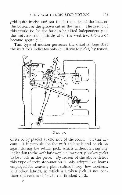
SIDE WEFT-FORK STOP-MOTION 193
grid quite freely, and not touch the sides of the bars or
the bottom of the groove cut in the race. The result of
this would be for the fork to be tilted independently of
the weft and not indicate when the weft had broken or
become spent out.
This type of motion possesses the disadvantage that
the weft fork indicates only on alternate picks, by reason
Fig. 57.
of its being placed at one side of the loom. On this ac-
count it is possible for the weft to break and catch on
again during the return pick, which without giving any
indication to the weft fork would allow partly broken picks
to be made in the piece. By reason of the above defect
this type of weft stop-motion is only adopted on loom.s
employed for weaving plain calico, linsey, low woollens,
and other fabrics, in which a broken pick is not con-
sidered a serious defect in the finished cloth.
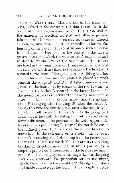
194 TAPPET AND DOBBY LOOMS
Centre Weft-fork.—This motion, as the name im-
pUes, is fixed in the centre of the shuttle race, with the
object of indicating on every pick. This is essential in
the majority of woollen, worsted and other expensive
fabrics in which broken and missing picks are considered
as defects, and which must be remedied prior to the
finishing of the piece. The construction of such a motion
is illustrated in Fig. 58. In the centre of the race a
groove is cut into which the weft feelers A may enter and
so drop below the level of the race-board. The feelers
are fixed in the winged bracket B supported by means of
the screws C which are fixed in the arms of the bracket Dsecured to the front of the going part. A sliding bracket
E on which are two inclined planes is placed to work
beneath the wings B^ and B-. A lateral motion is im-
parted to the bracket E by means of the rod F, which is
pivoted in the socket G secured to the breast-beam. As
the going part moves backward the sliding bracket E is
drawn in the direction of the arrow, and the inclined
plane H engaging with the wing B^ raises the feelers A
;
during this time the shuttle passes across the race, leaving
a pick of weft beneath the feelers. As the going part
again moves forward, the sliding bracket is forced in the
reverse direction. The presence of the weft supports the
feelers and keeps the wing B^ clear of the notch E^ cut in
the inclined plane H; this allows the sliding bracket to
move back to the extremity of its stroke. If, however,
the weft is missing, the feelers drop into the groove, and
the wing B^ enters the notch E^ ; this arrests the sliding
bracket on its return movement in such a position as to
stop the projection J, connected to the bracket by means
of the rod K, directly opposite the finger L. As the going
part comes forward the projection strikes the finger,
which, being fixed to the pistol lever, dislodges the start-
ing handle and so stops the loom. The spring F^ is neces-
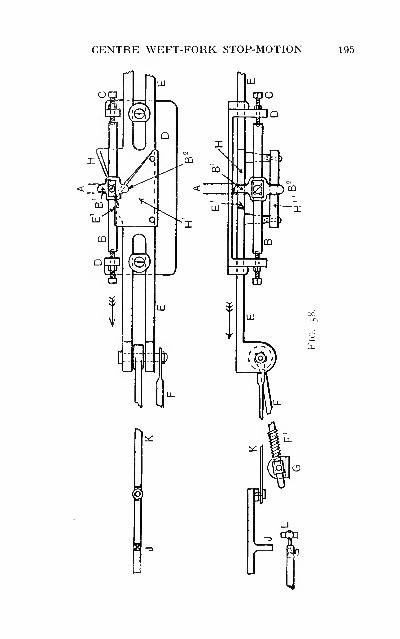
CENTRE WEFT-FORK STOP-MOTION 195
196 TAPPET AND DOBBY LOOMS
sary as an escape motion when the shding bracket is
locked by the absence of the weft; whilst the function
of the inclined plate H^ working in contact with the wing
B^, serves to prevent the feelers rising too high, also to
make their downward motion positive until the level of
the plate is reached, after which they are left quite free to
drop into the groove, or rest on the weft pick until they are
drawn off by the forward movement of the going part.
Defects due to Weft Stop-motions.—The weft maybe cut if the prongs are set to pass too far through the grid
or allowed to touch the sides of the bars. Weft loops
may be the result of defective working or irregular
tension on the weft ; broken picks if the weft stop-motion
fails, also short checks when weaving check patterns.
Constant knocking-off of the loom due to imperfect
setting and timing. The centre weft fork may be respon-
sible for throwing the shuttle or tearing the piece if the
feelers are not set to rise at the proper time.
Warp Protector Motion.—The object of this motion
is to protect the warp from being broken if the shuttle
through any cause is caught in the shed when the beat-up
is about to take place. There are two general types of
these motions, known as the " loose reed " and the " fast
reed " warp protectors. An illustration of the former is
given in Fig. 57, and is employed on most quick-running
looms weaving light and medium wefted fabrics. The
feature of this motion is that the reed is knocked out of
position when the shuttle is trapped in the shed, as an
alternative to the shuttle being forced through the warp,
breaking down some portion of the threads, which in
many instances would be equal to the length of the
shuttle.
The reed is held in position by fitting the top rib to the
groove cut in the hand tree; and at the bottom by the
angle plate J. This extends the full width of the reed,
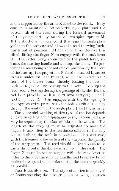
LOOSE REED WARP PROTECTOR 197
and is supported by the arms K fixed to the rod L. Easy
contact is maintained between the angle plate and the
bottom rib of the reed, during the forward movementof the going part, by means of two spiral springs M.
If the shuttle is in the shed at this time the angle plate
yields to the pressure and allows the reed to swing back-
wards out of position. At the same time the rod L is
tilted, lifting the finger N to engage with the rack lever
O. The latter being connected to the pistol lever, re-
leases the starting handle and so stops the loom. To pre-
vent the reed being knocked out of position by the force
of the beat-up, two projections P, fixed to the rod L, are set
to pass underneath the frogs Q, which are bolted to the
front of the breast beam, thereby locking the reed in
position to give a firm beat-up to the weft. To keep the
reed from vibrating during the passage of the shuttle, the
rod L is provided with a short arm carrying an anti-
friction pulley R. This engages with the flat spring S
and applies extra pressure to the bottom rib of the slay
through the medium of the angle plate J and the arms K.
The successful working of this type of motion depends
on careful setting and adjustment of the various parts, as
may be required by the class of fabric to be woven. Thelength of the frogs Q must be adjusted to meet the
fingers P according to the resistance offered to the slay
whilst pushing the weft into position. This will vary
with the fineness of the setting of the warp and the quality
of the warp yarn. The reed should be fixed so as to be
easily displaced if the shuttle is trapped in the shed. Thefinger N must be set to engage with the rack lever in
order to dislodge the starting handle, and bring the brake
motion into operation in order to stop the loom as quickly
as possible.
Fast Reed Motion.—This style of motion is employedon looms weaving the heavier builds of cloth, in which
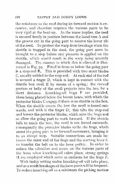
198 TAPPET AND DOBBY LOOMS
the resistance to the reed during its forward motion is ex-
cessive, and therefore requires the various parts to be
very rigid at the beat-up. As the name imphes, the reed
is secured firmly in position between the hand-tree A and
the groove cut in the going part to receive the lower rib
of the reed. To protect the warp from breakage when the
shuttle is trapped in the shed, the going part must be
brought to a stop before any pressure is applied on the
shuttle, which would result in the warp being severely
damaged. The manner in which this is effected is illus-
trated in Fig. 59. Fixed in front or below the going part
is a stop-rod B. This is provided with two stout blades
C, usually welded to the stop-rod. At each end of the rod
is secured a finger D, which is kept in contact with the
shuttle box swell E by means of a spring; the curved
portion or belly of the swell projects into the box for a
short distance. Knocking-off frogs F are provided,
these being placed below the breast beam, with which the
protector blades C engage if there is no shuttle in the box.
When the shuttle enters the box the swell is forced out-
wards, and with it the finger D; this tilts the stop-rod
and lowers the protector blades, which miss the frogs and
so allow the going part to work forward. If the shuttle
fails to reach the box, the swell is not forced outwards,
consequently the protector blades strike the frogs, which
arrest the going part in its forward movement, bringing it
to an abrupt stop. Suitable connections are made be-
tween the outer end of the frogs and the starting lever Gto transfer the belt on to the loose pulley. In order to
reduce the vibration and strain on the various parts of
the loom when knocking-off takes place, strong springs
H are employed which serve as cushions for the frogs F.
With faulty setting undue knocking-off will take place,
and as a result breakages of the loom parts will be frequent.
To reduce knocking-off to a minimum the picking motion
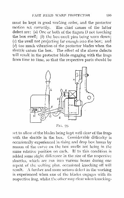
FAST REED WARP PROTECTOR 199
must be kept in good working order, and the protector
motion set correctly. The chief causes of the latter
defect are : {a) One or both of the fingers D not touching
the box swell; (b) the box-swell pins being worn down;(c) the swell not projecting far enough into the box; and(d) too much vibration of the protector blades when the
shuttle enters the box. The effect of the above defects
will result in the protector blade engaging with the frogs
from time to time, so that the respective parts should be
Fig. 59.
set to allow of the blades being kept well clear of the frogs
with the shuttle in the box. Considerable difficulty is
occasionally experienced in rising and drop box looms byreason of the curve on the box swells not being in the
same relative position on each. If to this condition is
added some slight difference in the size of the respective
shuttles, which are run into various boxes during one
repeat of the wetting plan, occasional knocking-off will
result. A further and more serious defect in the working
is experienced when one of the blades engages with its
respective frog, whilst the other may clear when knocking-
200 TAPPET AND DOBBY LOOMS
off takes place. This is chiefly due to the stop-rod being
twisted, or it may be due to the going part not working
squarely throughout its stroke. In any case, this defect
should receive immediate attention from the tuner, or
serious results, chiefly twisting of the lay or breakage of
the lay swords, will ensue.
Warp Stop-motion.—The function of this motion is to
stop the loom when a warp thread breaks. This acces-
sory to the power-loom is one to which considerable at-
tention has been directed during recent years. This
feature is no doubt largely due to the increasing develop-
ment of automatic w^eft-replenishing mechanisms. Until
recently warp stop-motions have been chiefly confined
to those branches of the weaving industry in which a
number of looms are under the supervision of one weaver—e.g., looms employed in weaving such goods as silk and
cotton umbrella cloths, Madras muslin and harness and
leno fabrics, where the breakage of a warp end has to be
repaired prior to finishing; if such goods contain a
number of warp floats they are classed as seconds. Abrief consideration of warp stop-motions discloses a multi-
plicity of parts, and also their somewhat delicate, if not
intricate, construction. These factors, accompanied bythe increased duties of the tuner attendant upon their
adoption, are features which have to some extent re-
tarded their initiatory stages. The tendency to the intro-
duction of these accessories to the power-loom does not
appear to be such as to warrant any prediction that they
win become general at an early date, or even that they
are absolutely essential on all classes of looms, although
for certain looms they may eventually become more
generally adopted. The main advantage which is to be
derived from their application is in the production of a
more perfectly woven piece, rather than in any increase
in loom production.
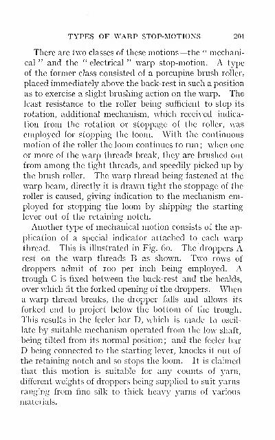
TYPES OF WARP STOP-MOTIONS 201
There are two classes of these motions—the " mechani-
cal " and the " electrical " warp stop-motion. A type
of the former class consisted of a porcupine brush roller,
placed immediately above the back-rest in such a position
as to exercise a slight brushing action on the warp. Theleast resistance to the roller being sufficient to stop its
rotation, additional mechanism, which received indica-
tion from the rotation or stoppage of the roller, wasemployed for stopping the loom. With the continuous
motion of the roller the loom continues to run ; when one
or more of the warp threads break, they are brushed out
from among the tight threads, and speedily picked up bythe brush roller. The warp thread being fastened at the
warp beam, directly it is drawn tight the stoppage of the
roller is caused, giving indication to the mechanism em-ployed for stopping the loom by shipping the starting
lever out of the retaining notch.
Another type of mechanical motion consists of the ap-
plication of a special indicator attached to each warpthread. This is illustrated in Fig. 60. The droppers Arest on the warp threads B as shown. Two rows of
droppers admit of 100 per inch being employed. Atrough C is fixed between the back-rest and the healds,
over which fit the forked opening of the droppers. Whena warp thread breaks, the dropper falls and allows its
forked end to project below the bottom of the trough.
This results in the feeler bar D, which is made to oscil-
late by suitable mechanism operated from the low shaft,
being tilted from its normal position; and the feeler bar
D being connected to the starting lever, knocks it out of
the retaining notch and so stops the loom. It is claimed
that this motion is suitable for any counts of yarn,
different weights of droppers being supplied to suit yarns
ranging from fine silk to thick heavy yarns of various
materials.
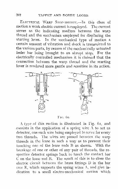
202 TAPPET AND DOBBY LOOMS
Electrical Warp Stop-motion.—In this class of
motion a weak electric current is employed. The current
serves as the indicating medium between the warpthread and the mechanism employed for displacing the
starting lever. In the mechanical type of motion a
certain amount of vibration and shock is transmitted to
the various parts, by reason of the mechanically actuated
feeler bar being brought to an abrupt stop. For the
electrically controlled mechanism it is claimed that the
connection between the warp thread and the starting
lever is rendered more gentle and sensitive in its action.
Fig. 6o.
A type of this motion is illustrated in Fig. 6i, and
consists in the application of a spring wire A to act as
detector, one such wire being employed to serve for every
two threads. The wires are passed between the warp
threads in the lease in such a way as to prevent their
touching one of the lease rods B as shown. With the
breakage of one or other of any pair of threads, the re-
spective detector springs back to touch the contact bar
C on the lease rod B. The result of this is to close the
electric circuit between the brass fittings D in the bar
tree E, which supports the spring wires A, and give in-
dication to a small electro-mechanical motion which
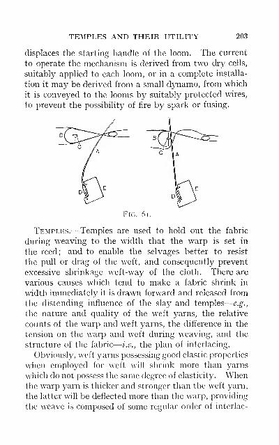
TEMPLES AND THEIR UTILITY 203
displaces the starting handle of the loom. The current
to operate the mechanism is derived from two dry cells,
suitably applied to each loom, or in a complete installa-
tion it may be derived from a small dynamo, from which
it is conveyed to the looms by suitably protected wires,
to prevent the possibility of fire by spark or fusing.
Fig. 6i.
Temples.—Temples are used to hold out the fabric
during weaving to the width that the warp is set in
the reed; and to enable the selvages better to resist
the pull or drag of the weft, and consequently prevent
excessive shrinkage weft-way of the cloth. There are
various causes which tend to make a fabric shrink in
width immediately it is drawn forward and released from
the distending influence of the slay and temples
—
e.g.,
the nature and quality of the weft yarns, the relative
counts of the warp and weft yarns, the difference in the
tension on the warp and weft during weaving, and the
structure of the fabric
—
i.e., the plan of interlacing.
Obviously, weft yarns possessing good elastic properties
when employed for weft will shrink more than yarns
which do not possess the same degree of elasticity. Whenthe warp yarn is thicker and stronger than the weft j^arn,
the latter will be deflected more than the warp, providing
the weave is composed of some regular order of interlac-
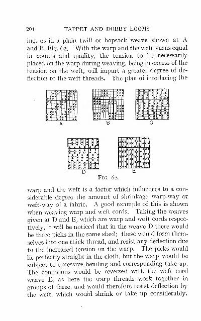
204 TAPPET AND DOBBY LOOMS
ing, as in a plain twill or hopsack weave shown at Aand B, Fig. 62. With the warp and the weft yarns equal
in counts and quality, the tension to be necessarily
placed on the warp during weaving, being in excess of the
tension on the weft, will impart a greater degree of de-
flection to the weft threads. The plan of interlacing the
XTa«« 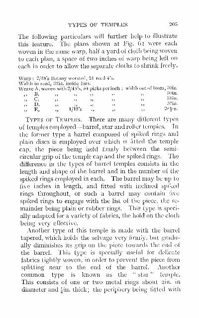
TYPES OF TEMPLES 205
The following particulars will further help to illustrate
this feature. The plans shown at Fig. 62 were each
woven in the same warp, half a yard of cloth being woven
to each plan, a space of two inches of warp being left on
each in order to allow the separate cloths to shrink freely.
Warp : 2/48's Botany worsted, 21 reed 4's.
Width in reed, 32in. inside lists.
Weave A, woven with 2/48's, 84 picks per inch ; width out of loom, oOin
,, B, „ „ „ „ ,, 30in.
,, C, „ „ „ ,, „ Shn.
,, D, „ „ „ „ ,, 32m.
„ E, „ 1/48's „ „ ,, 28Jm.
Types of Temples.—There are many different types
of temples employed—barrel, star and roller temples. In
the former type a barrel composed of spiked rings and
plain discs is employed over which is fitted the temple
cap, the piece being held firmly between the semi-
circular grip of the temple cap and the spiked rings. The
difference in the types of barrel temples consists in the
length and shape of the barrel and in the number of the
spiked rings employed in each. The barrel may be up to
five inches in length, and fitted with inclined spiked
rings throughout, or such a barrel may contain five
spiked rings to engage with the list of the piece, the re-
mainder being plain or rubber rings. This type is speci-
ally adapted for a variety of fabrics, the hold on the cloth
being very effective.
Another type of this temple is made with the barrel
tapered, which holds the selvage very firmly, but gradu-
ally diminishes its grip on the piece towards the end of
the barrel. This type is specially useful for delicate
fabrics tightly woven, in order to prevent the piece from
splitting near to the end of the barrel. Another
common type is known as the " star " temple.
This consists of one or two metal rings about 2in. in
diameter and {in. thick ; the periphery being fitted with
206 TAPPET AND DOBBY LOOMS
rows of fine pins. The rings are supported in the temple
brackets in a horizontal position, and take hold of the
selvage of the cloth only. This type is specially suitable
for fine fabrics which would be easily damaged by the
spiked rings or marked by the temple cap.
Roller Temples.—These are different from the
former types and consist of a roller which runs to the full
width of the piece, that is supported in a semicircular
trough placed between the fell of the cloth and the
breast beam. The surface of the roller is fluted at varying
angles, in order to obtain a rough surface and so maintain
a firmer grip of the fabric, which is in contact with half
of the circumference of the roller. Such temples are
employed for weaving light to medium fabrics, for which
the spiked ring type of temple is altogether unsuitable,
by reason of the spikes displacing and distorting the
threads during weaving.
Summary of Defects Caused by Temples.—Therings must be kept free from waste and grit, otherwise
they cannot rotate freely, and the cloth is prevented
from passing forward. The spikes may be damaged bybeing turned up at the point and formed into a small
hook. These catch on to the fibres and threads of the
fabric, and retard the forward movement of the piece
until they tear themselves free, thus damaging the
fabric. Many temple caps are made of brass; these
quickly wear down when weaving some classes of
goods, with the result that they fail to hold the piece out
to the width in the slay, the warp threads being chafed
down at the selvage. Occasionally the cap is indented
or the barrel pin strained by reason of the shuttle being
trapped in the shed, so that the piece is chafed while
passing through the temple or kept from working for-
ward freely. The temples may be set too near, so that the
weft is cut between the temple and the reed wires, or the
SELVAGES AND MATERIALS 207
wires become strained, causing reed marks in the piece.
Temple marks are sometimes due to tlie cap being set too
keen or close to the barrel, which in some fabrics leaves
the impression of the cap when the loom is left standing
any length of time; such defects are usually morepronounced and developed during finishing. Defective
beaming of the warp
—
i.e., tight or slack sections at the
lists— is a common cause of the temples not being
able to hold the piece effectively during weaving.
Selvages,—With the object of facilitating the opera-
tion of weaving and the subsequent processes of manu-facture, it is customary to put a selvage on each side of
piece-goods. Although that portion of the piece of cloth
formed by the selvages is not intended to be utilized in the
made-up garment, they may be considered as essential
from an economical standpoint. It is important that suit-
able yarns should be employed for the purpose, this being a
factor which very largely affects the weaving operation.
Selvages are very desirable in those woven fabrics whichare submitted to the operation of drying, after scouring,
etc., on the tentering machine, as such a process results in
the edges or selvages of the piece being rendered worthless.
Badly-formed selvages detract from the value of the piece
;
on the other hand, a well-woven selvage always adds to
the general appearance, and gives enhanced value to the
finished fabric.
The large diversity of cloths manufactured results in a
variety of selvages being used. Worsted cloths wovenin the grey to be piece-dyed may have the selvage
made of the same count and quality of yarn as that usedfor the warp, but with one or two cotton threads run in
from half to three-quarters of an inch from the edge to
form the selvage. Fancy worsteds are usually made witha solid coloured selvage of white or black yarns. Whiteselvages have the disadvantage of showing up any irre-
208 TAPPET AND DOBBY LOOMS
gularity of weaving or other defect. When black or other
dark-coloured yarn is employed it is advisable to run one
or two ends of some highly coloured yarn as a dividing
line between the selvage threads and those of the warp.
Woollen fabrics have a greater variety of selvages than
worsteds, including diversity of counts, quality and
colour. Woollen warps made from single yarns generaUy
require the yarn used for the selvages to be twofold, due
to the single yarn not being sufficiently strong to with-
stand the strain and chafing to which they are subjected
during weaving. Woollen cloths being submitted to
severe treatment during the finishing processes, particu-
larly in the scouring and milling operations, demandspecial attention in the selection of the yarn to be used
for the selvages. If the yarn selected does not possess
the same degree of felting property as the warp yarn,
long or short lists will result. Without trespassing too
far into the domain of the finisher, the general effect of
this may be briefly stated, as there is to a certain extent
something in common between the selection of unsuit-
able yarn and defective interlacing of the selvages during
weaving. Either error may be the cause of short or
long lists, which cockle the piece by allowing the centre
of the cloth to run slack during the finishing processes,
whilst the sides of the piece are held tight, and mustnecessarily bear all the drag. On the other hand, whenthe lists are too long the piece is held tight in the
centre, and the sides of the cloth run slack. This results
in a very unsatisfactory finish being obtained on the
piece, the centre and the sides not receiving the same
treatment in the subsequent finishing processes.
There are other defects in selvages for which the weav-
ing operation is more directly responsible. Occasionally
the weaver will alter the healding and the reeding of the
selvage threads as a remedy for frequent breakages
—
DEFECTIVE SELVAGES AND LISTED PIECES 209
probably the effect of the selection of faulty yarns, the
selvage threads being drawn two in a mail on the outside
edge to give additional strength. With thick woollen
yarns this is not advisable, as the lists have then a ten-
dency to curl, and may readily mill fast to the fabric if
subjected to too much milling. When the threads are
drawn double in this way, the list is increased in bulk,
which retards the various subsequent processes, and pro-
duces " listed pieces "
—
i.e., lack of finish at the sides.
Many pieces are spoiled by reason of one list being
badly woven while the other may be perfect. This maybe due to various causes. An imperfectly formed shed
will result in one or both the lists possessing a ragged
appearance. When the heald shafts are not adjusted
correctly, some of the threads will either hang slack in
the shed or be drawn excessively tight ; this prevents the
weft and the selvage threads from being drawn com-
pactly together.
Uneven tensioning of the weft in the shuttles will pro-
duce an unsatisfactory list. In a piece woven with two
or more shuttles running pick and pick, or two and two,
and the w^eaver using one or two change shuttles, it is
possible for the weft to be more heavily tensioned in one
shuttle than in another; usually this is the result of the
shuttle peg being set too low, so that the weft cannot pass
freely off the bobbin. The effect of this would be to
draw the lists tighter each time that particular shuttle
was running, which would show down the list of the piece
for a distance equal to the weaving length of the yarn on
the bobbin. Such a defect may be the cause of the piece
working out of the temples during weaving, and is a
frequent cause of a variation in the width of the finished
fabric. Cloths woven with two shuttles are liable to have
a defective list on one side of the piece only. When the
shuttles are started from the same side of the loom, the
210 TAPPET AND DOBBY LOOMS
tension on one selvage due to the drag on the weft will be
greater than on the other. This defect is accentuated
when the shuttles start from that side of the loom where
the eyelet of the shuttle, when at rest in the box, is nearest
to the picker.
When weaving with two or more shuttles on even pick-
ing, they should not be ahowed to run so that the
weft in each is spent and run off at the same time. It is
understood that the drag on the weft increases as the
bobbin empties, and the longer the bobbins or cops, the
greater the difference in the drag between a full andnearly spent bobbin. Take, for illustration, the weaving
of low woollens. The tendency during late years has
been to increase the bobbins in length, and by this meansobtain an increase in the number of yards on each bobbin
so as to reduce shuttle changing. When very long bob-
bins are used it will readily be seen to what extent
the drag on the selvage will vary from the full to the emptybobbin. Under such conditions the weft in the shuttles
should not be allowed to run off at the same time, but
arranged so that when one bobbin is full the other is half
spent. By this means the drag on the selvages is kept
more uniform, and better woven lists are produced.
Selvage Motions.—Frequently the selvages are re-
quired to be woven differently from the body of the cloth.
Many warp-faced cloths necessitate a plain or weft-faced
selvage to prevent them from curling. To produce such
selvages on the piece extra heald shafts, known as skele-
tons, are sometimes employed, these being operated by
means of special tappets or from spare jack levers in
dobby looms. There are, however, many devices knownto the tuner by which plain and other selvages can be
produced without the aid of special heald shafts. The
following are examples of a few of those generally
employed
:
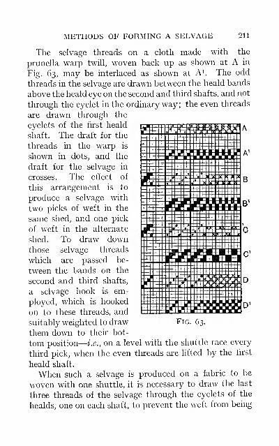
METHODS OF FORMING A SELVAGE 211
The selvage threads on a cloth made with the
prunella warp twill, woven back up as shown at A in
Fig. 63, may be interlaced as shown at A^. The odd
threads in the selvage are drawn between the heald bands
above the heald eye on the second and third shafts, and not
through the eyelet in the ordinary way; the even threads
are drawn through the
eyelets of the first heald
shaft. The draft for the
threads in the warp is
shown in dots, and the
draft for the selvage in
crosses. The effect of
this arrangement is to
produce a selvage with
two picks of weft in the
same shed, and one pick
of weft in the alternate
shed. To draw downthose selvage threads
which are passed be-
tween the bands on the
second and third shafts,
a selvage hook is em-
ployed, which is hooked
on to these threads, and
suitably weighted to draw
them down to their bot-
tom position
—
i.e., on a level with the shuttle race every
third pick, when the even threads are lifted by the first
heald shaft.
When such a selvage is produced on a fabric to be
woven with one shuttle, it is necessary to draw the last
three threads of the selvage through the eyelets of the
healds, one on each shaft, to prevent the weft from being
212 TAPPET AND DOBBY LOOMS
drawn back through the selvage up to the warp threads,
where the two picks are put into the same shed, or as analternative method to fix up a catch thread.
The draft B shows a method of healding the selvage
threads to obtain two picks in each of two different
sheds, when the weave for the piece is the ^^ twill.
The order of interlacing is given at B^. To prevent the
weft from drawing back through the selvage, if wovenwith one shuttle, the healding of the threads at each side
of the piece must be so arranged as to cross on theweft. This can be done by drawing the threads at -one
side of the piece on the first and third heald shafts, andthose on the other side on the second and fourth shafts.
By a slight modification of this principle a selvage maybe woven with two ends and two picks working together,
forming a hopsack or mat w^ave, the plan of the cloth
remaining ^^ twiU. This is illustrated at the draft C,
which indicates two threads drawn through separate
healds on the same shaft; these should be split in the
reed to prevent them rolling together, the order of inter-
lacing being as shown at C^.
To obtain a plain woven selvage on the J-^ twill, the
odd threads would be drawn between the heald bandsabove the eyelets on the first and third shafts, and the even
threads would be drawn between the heald bands on the
second and fourth shafts, as shown in the draft plan D,
the order of interlacing for the piece and selvage being
as in D^. Selvage hooks, as in example A, would be
necessary for each set of threads, to draw them down to
the level of the shuttle race. This would necessitate one
of the sets of threads in each selvage being left longer than
the other at the commencement of the warp, to avoid the
hook on one set when lifted to its highest point from
coming in contact with the alternate set of threads. Theeffect of this would probably be to hit them off the
CENTRE SELVAGES ON NARROW PIECES 213
shuttle race, and produce a defective interlacing or
render them liable to be broken with the passing shuttle.
Centre Selvages.—It is occasionally the practice
to weave narrow pieces, termed splits, side by side in a
broad loom, e.g., worsted trouserings are frequently
woven in this way. The warp pattern for the two pieces
will be different; the wetting pattern and the yarn for
each being the same, usually a solid colour. Pieces
woven in this way require to have the list ends of the
false selvage formed up the centre, one on each of the
two narrow pieces, stitched. These threads are not
stitched as tightly to the fabric as the outer lists, which
are bound to the fabric by reason of the weft doubling
back.
To prevent the centre selvages from fraying after the
pieces are separated by cutting up the centre, usually
after finishing, various methods are adopted. Theobject being to bind the outside threads on each of the
selvages to the piece by twisting two or more threads
round each other, and to interlace them with the weft
in such a way as to produce as near as possible a perfect
selvage.
When narrow pieces are regularly woven in a broad
loom it is advisable to employ one of the several centre
selvage motions obtainable for this purpose.
When such goods are only occasionally required there
are a few contrivances by which the desired result can
be obtained.
A very simple but effective method of stitching the
centre selvage consists of an arrangement usually termeda " monkey," the crossing of the stitching thread being
effected as shown in Fig. 64. A number of reeds are left
empty between the two pieces, to allow of them being
cut apart after finishing without in any way cutting the
warp threads. If the ground of the fabric is working
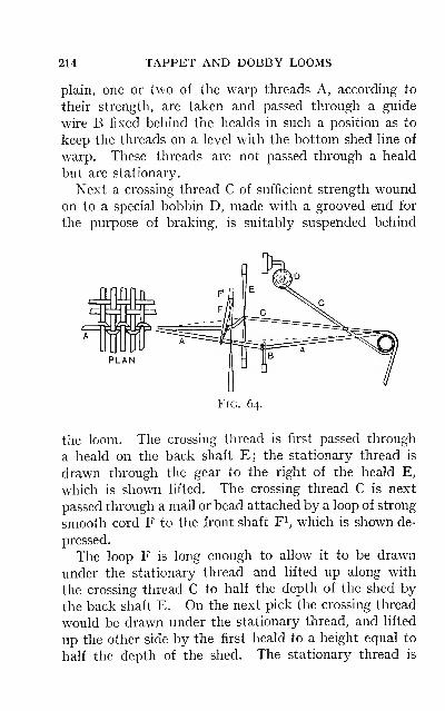
214 TAPPET AND DOBBY LOOMS
plain, one or two of the warp threads A, according to
their strength, are taken and passed through a guide
wire B fixed behind the healds in such a position as to
keep the threads on a level with the bottom shed line of
warp. These threads are not passed through a heald
but are stationary.
Next a crossing thread C of sufficient strength woundon to a special bobbin D, made with a grooved end for
the purpose of braking, is suitably suspended behind
PLAN
Fig. 64.
the loom. The crossing thread is first passed through
a heald on the back shaft E; the stationary thread is
drawn through the gear to the right of the heald E,
which is shown lifted. The crossing thread C is next
passed through a mail or bead attached by a loop of strong
smooth cord F to the front shaft F^, which is shown de-
pressed.
The loop F is long enough to allow it to be drawn
under the stationary thread and lifted up along with
the crossing thread C to half the depth of the shed by
the back shaft E. On the next pick the crossing thread
would be drawn under the stationary thread, and lifted
up the other side by the first heald to a height equal to
half the depth of the shed. The stationary thread is
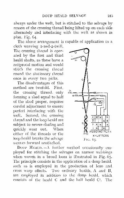
DOUP HEALD SELVAGE 215
always under the weft, but is stitched to the selvage byreason of the crossing thread being lifted up on each side
alternately and interlacing with the weft as shown in
plan, Fig. 64.
The above arrangement is capable of application to a
cloth weaving 2-and-2-twill.
The crossing thread is oper-
ated by the first and third
heald shafts, as these have a
reciprocal motion and would
stitch the crossing thread
round the stationary thread
once in every two picks.
The disadvantages of this
method are twofold. First,
the crossing thread, only
forming a shed equal to half
of the shed proper, requires
careful adjustment to ensure
perfect interlacing with the
weft. Second, the crossing
thread and the loop heald are
subject to severe chafing andquickly wear out. Wheneither of the threads or the
loop heald breaks the selvage
weaves forward unstitched.
Doup Heald.—A further method occasionally em-ployed for stitching the selvages on narrow webbings
when woven in a broad loom is illustrated in Fig. 65.
The principle consists in the application of a doup heald,
such as is employed in the production of leno andcross warp effects. Two ordinary healds, A and B,
are employed in addition to the doup heald, which
consists of the heald C and the half heald C^ The
PEGGING PLANm o
X=L1FTERS
P^IG. 65.
216 TAPPET AND DOBBY LOOMS
crossing threads D are all put on to a spare beam or
light roller.
The crossing thread is first drawn through the heald
of the shaft A, then passed through the doup eyelet
formed by the heald loop C^ being interlaced with the
mail or eyelet of the heald C. This is so arranged as to
allow the loop C^ to slide through the mail of C, whenthe crossing thread D is drawn down by the heald shaft
A to the right of the thread E as shown in Fig. 65. Thecrossing thread is drawn down on the alternate or left
side of E by the doup C and C^.
The method of working is further illustrated by the
pegging plan of the figure.
The first pick of the plan gives the position of the healds
and threads as shown.
The second pick indicates for the next change as follows
:
The heald A, the doup C and C^ and the thread D are
lifted, whilst the heald B and the thread E are down.
The third pick indicates the healds A and B lifted,
also both the threads D and E, but the doup heald Cand C^ is down, therefore the thread D is drawn down on
the left side of E and across it. Owing to the thread Dbeing hfted by the heald A, but depressed by the doupheald C and C^ it is essential to slacken the thread Dto facilitate the crossing. This is usually accomplished
by drawing the back-rest forward by some mechanical
contrivance, e.g., this may be performed by means of
a spare jack in the dobby.
The fourth pick is like the second—the crossing thread
is lifted, the thread E being depressed.
The manner in which the crossing thread interlaces
with the picks is shown at G. From this it will be ob-
served that the threads D and E work plain, also cross
and re-cross every two picks.
INDEX
Advantages of Indirect DrivingMotions, 19
Arrangement^ and Installation of
Looms, 2
Automatic Regulating Motion, 182
B
Balance Wheel, 17
Barrel Tappet, 50Beat-up, Resistance of the Warp
in different Weaves. 40Beating-up Motion, 28
The Position of the Reedwhen, 39
Belts, Open and Crossed, 7Care of, 8
Box Chains, Building up, 137Box Motion, Rising, 130
Chain-making for, 135Circular, 149
Working of, 155Box Motions, Different Classes,
129Boxes, Setting the, 134Bradford Tappet. 53Brake, Let-off, Advantnges and
Disadvantages, 166Motion, 162
Defective Work-ing, 164
Motions, 14, 23Ropes and Chains, 165
Breakages of Warp Threads, andCauses, 30
Calculations, Speed, 25for Positive Take - upMotions, 188
Centre Closed-shed Dobby, 97Selvages, 213Weft-fork, 194
Chain-making for Box Motions,
135Features in, 136
Chains, Building up Box, 137Change Wiieel Calculation for
Driving Tappets, 55Checking. Defective, 1 19
Motion, 117Circular Box Motion, 149
Boxes, Indicating to the,
152Skip-box Motion, 154Box Motions, Working of,
155Pattern Chains, 158
Classification of Power-looms, i
Clearing the Shed, 58Complicated Weft Plans, 148Construction of Tappets, 57
of the Going Part, 29Cover on Cloth, 99Crank Centres, Motions of Going
Part about, 36Cross Border Dobby, 97
Defective Checking, 119Picking, III
Shedding, 98Working of Negative Let-
off, 164of Positive Let-off, 177
Defects in Picking Motions, 123in Pieces due to Weft Stop-
motion, 196caused by Temples,
206
217
218 TAPPET AND DOBBY LOOMS
Depth of Shed and Effect on the
Warp, loi
Dividend Number for Positive
Take-up, i88
Dobby Alechanism, Easing the
Strain on, 103Dobcross, 78
Centre Closed-shed, 97Cross Border, 97Double-action Open - shed,
92Lever, 90
Doup Heald, Centre Selvage, 215Drafting for Backed and other
Cloths, 102
Driving of Looms, 6
Belts, Open and Crossed, 7
Care of, 8
Motions, 1
1
• Motion, Features of, 19'Wheels, Eccentric, 13
the Tappets, Change WheelCalculation, 55
Easing the Strain on DobbyMechanism, 103
Eccentric Driving Wheels, 13Motion of the Going Part, 38
Electrical Warp Stop-motion, 202
Factors in Eccentric INIotion of
the Going Part, 38Fast Reed Warp Protector
Motion, 197Features in Chain-making, 136
of Indirect Driving, 19
of Negative Motions, 183of Positive Motions, 186
Flying Shuttles, 30Friction Driving, 18
Going Part, Construction of the,
29Factors which Influence
Eccentric Motion, 38
Going Part, Motion aboutCrank Centres, 36
the
Nature of Motion impartedto, 34
Stroke of the, 23
HHarmonic Motion of the Heald, 88Hattersley Double-action Open-
shed Dobby, 92Heald, Doup, 215
Harmonic Motion of, S8Pulleys, 64
Healds, Nature of Motion desir-
able, 62HeavyWefting, How to Facilitate,
58
I
Indicating to the Boxes, 152Indirect Driving, Features andAdvantages of, 19
Installation and Arrangement of
Looms, 2
J
Jack-missings, 88
KKenyon's and similar Under-
motions, 69Knocking-off, Causes of, 198
Lag Cylinder, 85Lags Gathering, 85Let-off Motions, 161
Brake or Negative,
162
Positive, 168
Lever Dobbies, 90Listed Pieces, 209Lists, Tight and Slack, 208Looms, Classification of, i
Driving of, 6
INDEX 219
Looms, Installation and Arrange-ment of, 2
Right and Left Hand, 3—
—
^Transmitting Motionthroughout, 26
Loose Reed Warp Protector, 196
MMechanical Warp Stop-motion,
200Method of Drawing the Outline
of a Tappet, 60Motion of the Going Part about
the Crank Centres, 36Motion, Box, 44, 128
Circular Skip-box, 154Let-off and Setting-up, 45Picking, 42, noShedding, 43Under-pick, 119
Motions, Beating-up, 28
Brake, 14, 23Driving, ii
for Tappet Mechanism, Re-
versing, 63Selvage, 210Transmitting. 26Various, Relation and Tim-ing of, 41
Movement of the Going Part, 30
NNature of Motion desirable for
the Healds, 62Imparted to the Going
Part, 34Negative Let-off Motion, Causes
of Defective Working, 164—— Take-up Motions, 179— Automatic Regulatingof, 182
• Features of, 183
OOpen and Crossed Belts, 7
Outline of a Tappet, Method of
Drawing, 60Over-pick—Pick-at-will Motion,
112
Pattern Chains for Circular Boxes,
158Perfect Slope of Shed, 102
Pick-at-will Motion, Over-pick,
112Pickers and Picking Straps, 126
Picking, Defective, inEarly and Late, 122
Mechanism, 105• Motion, Timing of, 42
Under-pick, Timingand Setting, 121
Motions, Timing and Set-
ting, no. III
Defects in, 123
Position of the Reed when Beat-
ing-up, 39Positive Let-off Motions, 168
Regulating of,
171
Defects due to,
177—•— Take-up Motions, 184Features of, 186
—— Calculation for,
188
Tappet Mechanism, 72Power-looms, Classification of, i
Production and Speed, 24
Races, Wood and Iron Shuttle, 30Reed, Position of, when Beating-
"P. 39Reediness in Cloth, 98Regulating Motion, Automatic,
182
Relation and Timing of the Various
Motions, 41Resistance to the Beat-up in dif-
ferent Weaves, 40Reversing Motions for Tappet
Mechanism, 63Right and Left Hand Looms, 3
Rising Box Motion, 130
220 TAPPET AND DOBBY LOOMS
Sectional Tappets, 48Selvage Motions, 210Selvages, 207
Badly-formed, loi
Centre, 213Stitched by Doup Heald,
215Setting-up Motions, 178
Negative, 179Positive, 184
Shady Pieces due to UnevenWeft, 128
Shed, Depth of, loi
Perfect Slope of, 102Shedding, Defective, 98
Mechanism, 46Motion, Timing of, 43Uneven, 100
Shrinkages of different Weaves,204
Shuttle Box, its Influence on the
Shuttle, 108Boxes, Tight and Slack, 124
• Checking Motions, 117Easing Motions, 116Flying, 30Races, 30
Shuttles, 107Sizing Warps, 59Skip-box Motion, Circular, 154Speed and Production, 24
Calculations, 25Splits, 213Springs, 64Stocks and Bowls. 66Stripped Weft, 125Stroke of the Going Part, ;^^
Take-up Motions, 178Calculations, 188— Negative, 179Positive, 184
Tappet, Barrel, 50Bradford, 53Construction, 57Mechanism, Positive, 72Sectional, 48
Temples, 203, 205Summary of Defects due to,
206Tension of the Warp, varying, 163Timing of the Pick, 121
of the various Motions, 41and Setting, DobcrossDobby, 81
Transmitting Motion throughout
the Loom, 26
U
Under-motions, 69Under-pick Motion, 119Uneven Shedding, 100
V
Variety of Weave Effect, 56Varying the Tension of the Warp,
163
WWarp Floats due to Jack-miss-
ings, 88Protector Motions, 196
Fast Reed, 197Stop-motions, Mechanical,
200Electrical, 202
Varying the Tension of, 163Waste of Weft, 125Weave Effect, Variety of, 56Weft Cutting due to Defective
Shuttle-box, 124Temples, 206
Weft Stop-motion, Defects dueto, 196
Centre Wefi-fork, 194Side Weft-fork, 191
Staplings, loi
Wefting Plans, Complicated, 148Weights, 63Wood and Iron Shuttle Races, 30Woodcroft Tappet, 72, y6Working of Circular Box Motions,
155
INDEX TO ADVERTISEMENTS.
George Hodgson, Limited . . . . • .
Tattersall & Holdsworth's Globe Works and Stores .
Wm. Dickinson & Sons
George Hattersley & Sons, Limited iv
Wm. Smith & Brothers, Limited v
'•Theory of Sizing" vi
"The Textile Manufacturer" vii
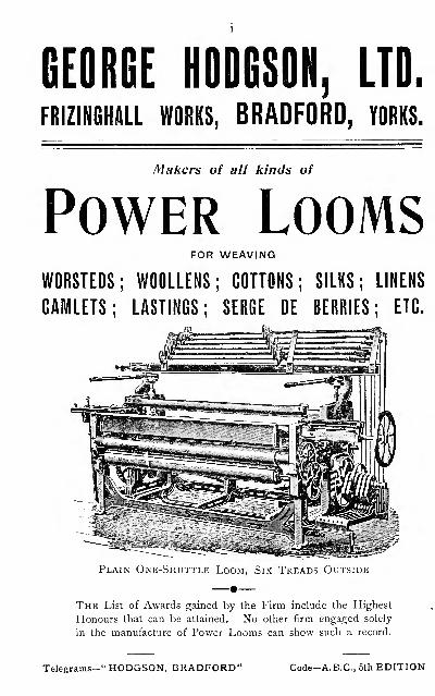
GEORGE HODGSON, LTD.
FRIZINGHALL WORKS, BRADFORD, YORKS.
Makers of all kinds of
Power LoomsFOR WEAVING
WORSTEDS; WOOLLENS; COTTONS; SILKS; LINENS
CAMLETS; EASTINGS; SERGE DE BERRIES; ETC.
Plain One-Shuttle Loom, Six Treads Outside
The List of Awards gained by the Firm include the Highest
Honours that can be attained. No other firm engaged solely
in the manufacture of Power Looms can show such a record.
Telegrams-" HODGSON, BRADFORD" Code-A.B.C, 5th EDITION
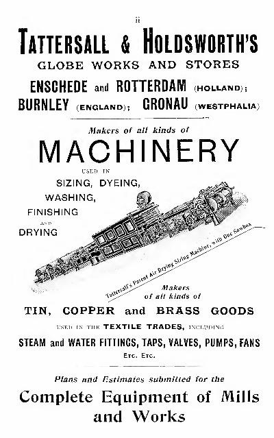
TaTTERSALL & HOLDSWORTH'SGLOBE WORKS AND STORES
ENSCHEDE and ROTTERDAM (holland),
BURNLEY (ENGLAND); GRONAU (WESTPHAUA)
Makers of all kinds of
MACHINERYUSED IN
SIZING, DYEING
WASHING,
Makerskinds
TIN, COPPER and BRASS GOODSUSED IN JiiE TEXTILE TRADES, including
STEAM and WATER FITTINGS, TAPS, VALVES, PUMPS, FANS
Etc. Etc.
Plans and Estimates submitted for the
Complete Equipment of Mills
and Worlds
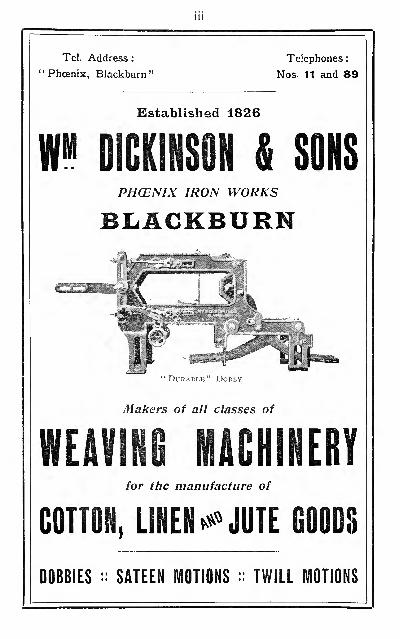
Ill
Tel. Address : Telephones :
Phoenix, Blackburn" Nos. 11 and 89
Established 1826
m DICKINSON & SONSPHCENIX IRON WORKS
BLACKBURN
Durable" Dobby
Makers of all classes of
WEAVING MACHINERYfor the manufacture of
COTTON, LINEN •»' JUTE GOODS
DOBBIES :: SATEEN MOTIONS :: TWILL MOTIONS
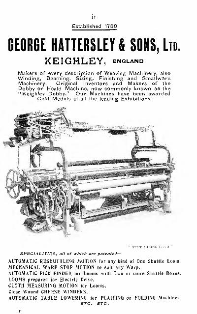
IV
Established 1789
BEORGE HATTERSLEY & SONS, Ltd.
KEIGHLEY, enqland
Makers of every description of Weaving Machinery, alsoWinding, Beaming, Sizing, Finishing and SmallwareMachinery. Original Inventors and Makers of theDobby or Heald Machine, now commonly known as the" Keighley Dobby. " Our Machines have been awarded
Gold Medals at all the leading Exhibitions.
WEFT MIXING LOOM
SPECIALITIES, all of which are patented—
AUTOMATIC RESHUTTLING MOTION for any kind of One Shuttle Loom.
MECHANICAL WARP STOP MOTION to suit any Warp.
AUTOMATIC PICK FINDER for Looms with Two or more Shuttle Boxes.
LOOMS prepared for Electric Drive.
CLOTH MEASURING MOTION for Looms.
Close Wound CHEESE WINDERS.AUTOMATIC TABLE LOWERING for PLAITING or FOLDING Machines.
ETC. ETC.
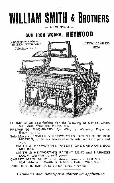
WILLIAM SMITH & Brothers— LIMITED -
SUN IRON WORKS, HEYWOODTelegraphic Address
:
"SMITH'S, HEYWOOD"Telephone No. 2
ESTABLISHED1824
LOOMS of all descriptions for the Weaving of Cotton, Linen,Silk, Jute, Woollens, Hemp, etc.
PREPARING MACHINERY for Winding, Warping, Dressing,Beaming, etc.
Sole Makers of SMITH &. HEYWORTH'S PATENT DROP BOXMOTION, up to six boxes at each side, working pick andpick.
SMITH & HEYWORTHS PATENT ONE-CARD ONE-BOXMOTION.
SMITH & HEYWORTH'S PATENT LENO and HARNESSLOOM, working up to 5 cover.
CARPET MACHINERY of all descriptions, and LOOMS up to
16/4 wide, with Smith & Hobson's Patent Wire Motion.
PRINTING DRUMS up to 70 feet circumference.
Estimates and Descriptive Matter on application
Theoky of SizingBy HARRY NISBET,
Weaving Master, Technical School, Bolton, Author of Grammar of Textile Desipi.Member of The Textile Institute. Contributor oi i^x\\c\^s on Preliminary Operations
of Weaving in The Textile Manufacturer.
CONTENTS :
Chapter I. Introduction : The Commercial and Technical Policy of
Sizing Yarn.
Chapter II. Classification ok Sizing Ingredients : Their Essential
Constituents, Properties and Specific Purpose. Also the Physical
Structure and Microscopical Appearance of Different Varieties of
Starch Granules, and Methods of Distinguishing Them. Mildew :
Its Cause, Effect, and Prevention.
Chapter III. Size Mixing and Size-Mixing Plant. Also Size-Boiling
and Automatic Size Feeding Devices.
Chapter IV, Data for Size-Mixing Recipes. Also Useful Formulae andData Relating to Sizing Ingredients, Size Mixing, and Size-MixingApparatus.
"This is a concise and very handy manual of 75 pages, within which the
author succeeds to a commendable degree in presenting the subject in goodform. . . . He shows that he has a good knowledge of the subject of whichhe has written."
—
The I'extile Merairy." It can be commended as a useful practical work."
—
Belfast News-Letter." This most practical and authoritative manual will no doubt prove
of great value to manufacturer, sizer and technical student alike."
—
TheBlackburn Times.
"Always clear, concise, and to the point, the book has the additional
authority derived from personal observation and experiment."
—
NorthernWhig.
" Is an admirable example of what a good technical manual should be
—
written in plain and clear English, and amply illustrated."
—
Notlinghavi
Guardian."There was a distinct need for such a treatise: . . . much information
is imparted in reference to size mixing and boiling ; and, as might be
expected, the book contains ample data and formuk-e of a reliable character."
—
Cotton Factory Times.
"Mr Nisbet's knowledge is that of an expert, based on both personal
observation and experiment ; and the way he treats of this subject gives oneconfidence that the book must prove of inestimable value to textile workersand manufacturers of textile fabrics."
—
Yorkshiie Factory Times.
"An interesting volume summarising, in a concise form, a multitude of
data which one cannot consult without benefit."
—
LIndustrie Textile.
"This textile expert has written a very valuable treatise on Sizing."
—
Spinner and PVeber, Leipzig.
Crown 8vo. 80 pp. Illustrated. Price 2/6 Net, Post Free, 2/9.
Obtainablefrom all Booksellers or directfrom the Publishers
:
EMMOTT & CO., Limited, 65 King Street, MANCHESTER,
and 20 Bedford Street, LONDON, W.C.
The
Textile ManfuacturerA Practical Journal for
Millowners, Machinists, Dyers, Calico Printers,
Bleachers, &c.
PliOFUSELT ILLUSTRATED
Contains more Original Contributions by the Leading
Experts than any other Textile Journal
The reputation of the "Textile Manufacturer" has been
built up on the excellence and high standard of its
literary contents, and its claim to be the
WORLD'S PREMIER JOURNAL
of the Textile Industry was never more irrefutable than
the present time. Its Contributors are recognised as
the very highest authorities in their respective branches
of the Trade.
NOTICES OF ALL THE LATEST TYPES OF TEXTILE
MACHINERY, SPECIMENS OF WOVEN FABRICS,
DYED SAMPLES AND PLATES OF ORIGINAL DESIGNS
Published on the i^th of every Month. Price n.
Annual Subscription, 125., post free to any part of the World
Speciynen Copy Free on Application to—EMMOTT & COMPANY, LIMITED
65 King Street, Manchester, and
20 Bedford Street, London, VV.C.


SOUTHEASTERN MASSACHUSETTS UNIVERSITY
3 ETE2 D D3Eli 3 3 fi
E>ate Loaned
SPECIAL COLL TS1493.R5 1912Roberts, Thomas.Tappet and dob by looms
^6