the evolution of uwb and ieee 802.15.3a for very...
TRANSCRIPT

The Evolution of UWB and IEEE 802.15.3a for Very High Data Rate WPAN
By Ketan Mandke, Haewoon Nam, Lasya Yerramneni, and Christian Zuniga
EE 381K-11 Wireless Communications
UWB Group, The University of Texas at Austin
Prepared for Dr. T. S. Rappaport May 6, 2003

1
ABSTRACT The proliferation of wireless communication devices in our lives shows no sign of stagnation. The ever-growing demand for higher quality media and faster content delivery where we work, live, and play drives the quest for higher data rates in communication networks. To meet this demand for capacity in the wireless personal area network (WPAN) space, the IEEE 802.15.3a task group has set out to define a very high data rate alternate physical layer for IEEE 802.15.3, the current high data rate WPAN standard. The IEEE 802.15.3a task group is currently in the process of reviewing proposals presented by a variety of companies (including Texas Instruments, Intel, XtremeSpectrum, etc). All of the current proposed physical layers employ ultra wideband (UWB) communication. The goal of this paper is to create a clear picture, or “snapshot,” of the current state of UWB communications and its relation to the standardization efforts of IEEE 802.15.3a. The paper includes a discussion of the benefits of UWB radio, the regulatory environment of UWB, and the design issues and trade-offs which face WPAN standards makers. This paper should aid the reader in understanding the motivations for and implications of the convergence of IEEE 802.15.3a and UWB radio. The IEEE is expected to release an approved standard in mid-2004.

2
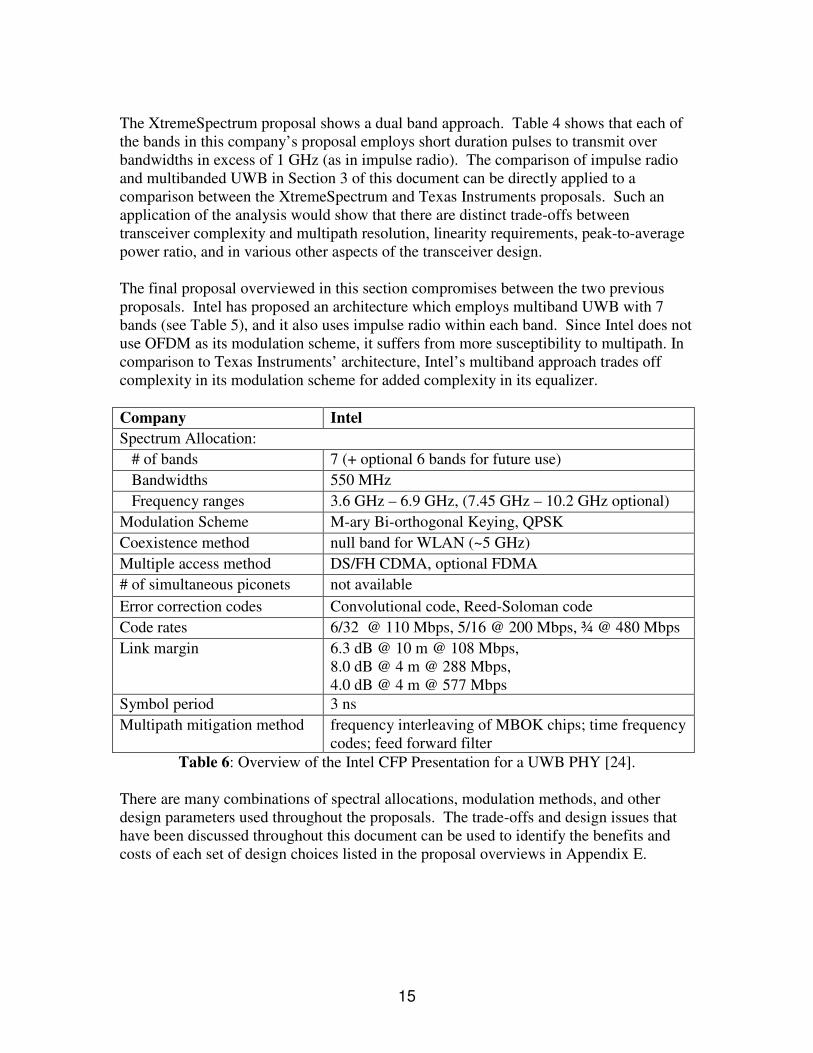
1.0 INTRODUCTION The IEEE 802.15 working group develops personal area network consensus standards for short distance wireless personal area networks (WPANs). Task group 3 has developed a standard (IEEE 802.15.3) to deliver data rates from 20 Mbps to 55 Mbps over short range (less than 10 meters) WPANs. Table 1 lists a variety of wireless applications in the WPAN space and their estimated requirements for data rates. Appendix A contains a more detailed description of these applications and their data rate requirements.
Application Min Data Rate Max Data Rate
H.323 / T.120 Video Conferencing 188+ Mbps 1.4+ Gbps Home Theater 43 Mbps 56.8 Mbps Interactive Application (e.g. gaming) 76.8+ Mbps unknown Content Downloading (e.g. photos, MP3, CD, movies) 90+ Mbps unknown
Table 1: Estimated data rates for various WPAN applications [1]. IEEE 802.15.3 would not be able to provide the data rates necessary to support many of these applications. In November 2001, an additional task group within IEEE 802.15, Task Group 3a, was formed to identify a higher speed physical layer alternative that could support data rates between 110 Mbps and 480 Mbps over short ranges of less than 10 meters. The February 2002 FCC approval of ultra wideband (UWB) devices prompted many companies to consider UWB radio when proposing physical layers to IEEE 802.15.3a. This paper will explore a range of issues concerning UWB, specifically as they relate to the IEEE 802.15.3a standards group. This discussion will begin with an introduction of UWB, the FCC regulations on UWB, and a detailed description of how IEEE 802.15.3a fits into the wireless standards efforts of IEEE 802. 1.1 The Evolution of UWB The concept of ultra wideband communication originated in the early days of radio. In the 1900s, the Marconi spark gap transmitter (the beginning of radio) communicated by spreading a signal over a very wide bandwidth. This use of spectrum did not allow for sharing, so the communications world abandoned wideband communication in favor of narrowband or tuned communication in which the FCC governed spectrum allocation. The FCC provides guidelines for radiated power in the bandwidths of these communications systems and for incidental out of band radiated power. These incidental radiated power limits were the motivation for various organizations to challenge the paradigm of narrowband communications, in an ongoing effort to squeeze capacity out of a highly regulated spectrum. The Shannon-Hartley theorem states that channel capacity grows linearly with increases in bandwidth and decreases

3
logarithmically with decreases in the signal to noise ratio (SNR). Although this relation is only exact under a considerable caveat, it does suggest how capacity is an impetus for UWB communication. Many companies argued that they should be allowed to intentionally transmit at the incidental radiated power limits (where they could already transmit accidentally) over an ultra-wide bandwidth to take advantage of this capacity potential. This argument was the motivation for the FCC approval of UWB devices. In February of 2002, the FCC amended their Part 15 rules (concerning unlicensed radio devices) to include the operation of UWB devices without a license. The FCC defines UWB signals as having a fractional bandwidth of greater than 0.20 or a UWB bandwidth greater than 500 MHz. UWB bandwidth is defined as “the frequency band bounded by the points that are 10 dB below the highest radiated emission” [2].
Figure 1: Spectrum of UWB Signal Compared with Wi-Fi (802.11a) Signal [3].
The FCC ruling allows UWB communication devices to operate at low power (an EIRP of -41.3 dBm/MHz) in an unlicensed spectrum from 3.1 to 10.6 GHz (see Figure 1). The low emission limits for UWB are to ensure that UWB devices do not cause harmful interference to (i.e. coexist with) “licensed services and other important radio operations” [2] (e.g. 802.11a devices). Table 2 summarizes a few of the guidelines most relevant to the use of UWB technology in WPAN devices.
Operating frequency range 3.1 GHz to 10.6 GHz Average radiated emissions limit
Frequency range (MHz) EIRP in dBm (indoor/hand held) 960-1610 -75.3 / -75.3
1610-1900 -53.3 / -63.3 1900-3100 -51.3 / -61.3
3100-10600 -41.3 / -41.3 Above 10600 -51.3 / -61.3
Peak emission level in band 60 dB above average emission level Max unacknowledged transmission period 10 seconds
Table 2: FCC requirements for indoor and hand held UWB systems [2].
Many manufacturers of PCS, GSM, and ISM band devices adamantly opposed the approval of FCC devices because of the additional noise it would introduce in their

4
systems. Because of this opposition, the FCC made guidelines which are very conservative with respect to the receiver sensitivities of most out of band devices. The combination of a potential for coexistence, fine multipath resolution, tremendous capacity potential, advances in CMOS technology, and a simpler RF architecture due to reduced complexity in terms of filtering [4] makes UWB an attractive alternative to narrowband technology. The IEEE 802.15 Task Group 3a is currently evaluating alternative physical layer designs (especially UWB) for high data rate WPAN systems. The next section characterizes this group’s place in the wireless standards efforts of IEEE 802, and discusses the evolution and projected goals of Task Group 3a in deploying a UWB standard for WPAN within the FCC regulations. 1.2 UWB and IEEE 802.15.3a The indoor wireless standards effort can be broadly categorized into three standards groups. The first of which is IEEE 802.11, responsible for Wireless Local Area Network (WLAN) standards. This deployment can provide connectivity in homes, factories, and “hot spots” (public wireless internet access networks [5]). The IEEE 802.16 group is responsible for Wireless Metropolitan Area Networks (WMAN) standards. This body is concerned with fixed broadband wireless access systems, also known as “last mile” access networks. IEEE 802.15, of which we are concerned with, is responsible for Wireless Personal Area Network (WPAN) standards.
Figure 2: IEEE 802.15, standards group responsible for WPAN standards.
The efforts of IEEE 802.15 are divided up into four main areas (as shown in Figure 2): (1) Task Group 1 (TG1) is creating a WPAN standard based on Bluetooth™ to operate in the 2.4 GHz ISM band; (2) TG2 is concerned with the coexistence of unlicensed spectrum devices; (3) TG3 is responsible for high data rate (in excess of 20 Mbps) WPAN standards; and (4) TG4 is creating a low data rate, low power WPAN standard. An additional group, TG3a, was created to investigate physical layer alternatives for high data rate WPAN systems (i.e. alternatives for the IEEE 802.15.3 physical layer). TG3a established technical requirements and selection criteria for a WPAN physical layer in December 2002 (which will be covered in greater detail in later sections of this
IEEE 802.15 WPAN
TG1 Bluetooth™
TG2 Coexistence
TG3 High Data
Rate WPAN
TG4 Low Data
Rate WPAN
TG3a Very High Data Rate WPAN

5
paper), and is currently reviewing proposals or presentations submitted by various companies (including Time Domain, Intel, Texas Instruments, XtremeSpectrum, etc.). Appendix B contains a more detailed description of the timeline for TG3a presented in [6]. If the standardization process finishes according to this timeline, high data rate WPAN devices with UWB IEEE 802.15.3a could be available before 2005. TG3a has set out to develop a flexible standard which will enable high data rate WPAN (110 Mbps at 10m, 200 Mbps at 4m, and 480 Mbps at an unspecified distance) over a cost effective architecture. This new standard will enable a broad range of applications including the wireless transmission of images and video. The goal of this paper is to explore the unique design issues specific to UWB, engineering trade-offs faced by standards developers, and the current state of IEEE 802.15.3a. Section 2 will discuss the unique aspects of indoor UWB channels and the four of the proposed TG3a channel models. Section 3 compares a traditional impulse radio approach to UWB with a more recent multibanded approach (which has been employed in many TG3a proposals). Section 4 details the requirements and specifications set forth by IEEE 802.15.3a, and categorize the proposals being considered in order to form a clear picture of the current state of UWB technology as it relates to WPANs. 2.0 UWB CHANNEL MODEL The goal of UWB channel modeling is to understand the characteristics of the propagation channel where UWB devices are operating in order to help implement an efficient high data rate communications system. The model chosen by TG3a should be relatively simple so that physical layer proposers can easily use the model to test and evaluate the performance of their proposal in typical environments. In order to optimize the utility of this channel model, TG3a must balance the trade-off between the need for a simple model and the accuracy of the model. This section discusses models for indoor fading channels that are being considered by IEEE 802.15.3a (since these are the channels of interest for most UWB devices). The basic parameters to consider in a channel model are path loss and the behavior of multipath in the relevant environments (such as office or home, line of sight (LOS) or non-line of sight (NLOS), etc.). For a path loss model of a UWB channel, the narrowband model (known as Friis free space model) based on the assumptions of a flat frequency response and isotropic antennas can be used to give a good approximation of the UWB channel [8]. Since it may be difficult to consider all the characteristics of a multipath channel in a single simple model, TG3a has chosen to focus only on the following primary characteristics of the indoor multipath channel: 1) RMS delay spread, 2) the power decay profile, and 3) the number of multipath components. 2.1 Summary of Measurements and Proposed Models 1) “UWB Channel Modeling Contribution from Intel,” J. Foerster and Q. Li [8].

6
In their measurements, the authors sound the channel over the frequency range of 2 – 8 GHz using 0.167 ns baseband pulses, which corresponds to a 5 cm spatial resolution of the multipaths. This is a high resolution for the indoor environment that 802.15.3a devices will operate on. Measurements were made over distances from 1 to 20 meters, and included LOS and NLOS cases.
Three channel models – the Rayleigh tap delay line model (same as the one used in 802.11), the ∆-K model, and the Saleh-Valenzuela (S-V) model – were compared and the paper showed that the S-V model was able to best fit the measured channel characteristics. In addition, the measurement data was compared with the Rayleigh and lognormal amplitude distributions, and the results showed that the lognormal distribution fit the characteristics of the measurement data better than the Rayleigh distribution. Hence, the final proposed model was the S-V model with a lognormal fading distribution on the amplitudes of multipath components.
2) “Empirically Based Statistical Ultra-Wideband Channel Model,” M. Pendergrass [9].
These measurements are made in the 3 – 5 GHz band using 1.7 ns baseband pulses, which have a spatial resolution of 51 cm. The ∆-K model uses only a single exponential to characterize path arrivals. Thus it cannot characterize mean excess delay and RMS delay spread for LOS and NLOS channel conditions simultaneously. This proposal recommends that a better model than the ∆-K is necessary and suggests an extension of the ∆-K model using ∆ = 0.5 ns. The measurement data was compared with simulated data produced by the IEEE 802.11 channel model and the ∆-K model based on various environments.
3) “Radio Channel Model for Indoor UWB WPAN Environments,” J. Kunisch and J. Pamp [10]
These measurements were performed with omnidirectional antennas on both transmitter and receiver in an office with LOS, NLOS, intra-office, and inter-office scenarios. The measured frequency range is 1 – 11 GHz; and the separation distance was varied from 3 to 10m. The model is based on the Saleh-Valenzuela (S-V) approach. However, unlike the traditional S-V approach, the model accounts for strong individual echoes which are generated according to a simple algorithm based on the imaging method. Consequently, the model allows determining space-variant impulse responses; in particular, individual echoes caused by receiver movement are accounted for. This means that the model reproduces Doppler behavior of the channel, as induced by the receiver movement.
4) “The Ultra-Wide Bandwidth Indoor Channel: from Statistical Model to Simulations,” A. Molisch, M. Win, and D. Cassioli [7]

7
This model uses 2ns baseband pulses, a minimum spatial resolution of 60cm, to sound the channel. The authors’ measurements in the 1.5 – 3 GHz frequency band are not of high interest to UWB communications (which operates from 3.1 – 10.6 GHz). Multipath is modeled with the Nakagami distribution, which is observed to have better fading behavior than a Rayleigh distribution.
2.2.0 Intel’s Proposed UWB Channel Model The FCC allows a maximum bandwidth of 7.5 GHz, from 3.1 – 10.6 GHz, for UWB communication. Among the proposed models above, only the model proposed by Intel provides enough spatial or time resolution to study the multipath fading characteristics of a UWB system. The Intel measurements suggest an interesting phenomenon. Path arrivals tend to come in clusters rather than uniformly spaced in time, which was also observed in several other indoor channel measurements [12, 14, and 15]. The S-V model seems to best fit this clustering phenomenon. Single exponential decay cannot model both mean excess delay and RMS delay spread for LOS and NLOS channel environments at the same time, while the Intel model can by using a double exponential decay (which is capable of modeling these parameters simultaneously – see Appendix C). The narrow pulses used in the Intel measurements provide high multipath resolution. The Intel measurements, taken in the UWB band, observe a lognormal distribution for multipath fading; this distribution fits the measurements better than both the Rayleigh and Nakagami distributions. The model also statistically characterizes the multipath arrival times, thus providing double exponential decay (which generates impulse responses close to the measured cases). For these reasons, the Intel model provides all the tools necessary to test UWB systems with reasonable accuracy. 2.2.1 Model Parameters The following six parameters are important in defining the Intel model:
• Λ = cluster arrival rate; • λ = ray arrival rate (i.e., the arrival rate of path within each cluster); • Γ = cluster decay factor; • γ = ray decay factor; • σ1 = standard deviation of cluster lognormal fading term (dB). • σ2 = standard deviation of ray lognormal fading term (dB). • σx = standard deviation of lognormal shadowing term for total multipath
realization (dB). 2.2.2 Channel Characteristics The following characteristics of the channel are used to determine the previous parameters: .

8
• Mean excess delay • RMS delay spread • Number of multipath components (defined as the number of multipath arrivals
that are within 10 dB of the peak multipath arrival) • Power decay profile
2.2.3 Channel Parameters Since power decay profile is difficult to measure, only the first three characteristics above are used to characterize a channel. The following table lists some model parameters for four different channel characterizations from measurement data by Intel [11].
Target Channel Characteristics CM 11 CM 22 CM 33 CM 44 Mean excess delay (nsec) ( mτ ) 5.05 10.38 14.18
RMS delay (nsec) ( rmsτ ) 5.28 8.03 14.28 25
NP10dB 35 NP (85%) 24 36.1 61.54 Model Parameters Λ (1/nsec) 0.0233 0.4 0.0667 0.0667 λ (1/nsec) 2.5 0.5 2.1 2.1 Γ 7.1 5.5 14.00 24.00 γ 4.3 6.7 7.9 12
1σ (dB) 3.3941 3.3941 3.3941 3.3941
2σ (dB) 3.3941 3.3941 3.3941 3.3941
xσ (dB) 3 3 3 3
Model Characteristics Mean excess delay (nsec) ( mτ ) 5.0 9.9 15.9 30.1
RMS delay (nsec) ( rmsτ ) 5 8 15 25
NP10dB 12.5 15.3 24.9 41.2 NP (85%) 20.8 33.9 64.7 123.3 Channel energy mean (dB) -0.4 -0.5 0.0 0.3 Channel energy std (dB) 2.9 3.1 3.1 2.7
Table 3: Indoor multipath channel characteristics and corresponding model parameters from Intel measurements [11].
The next section will compare the impulse radio approach to ultra wideband communication with a more recent multibanded approach. These two approaches vary in their complexity and performance over the indoor multipath channel discussed in this section.
1 This model is based on LOS (0 – 4 m) channel measurements. 2 This model is based on NLOS (0 – 4 m) channel measurements. 3 This model is based on NLOS (4 – 10 m) channel measurements. 4 This model was generated to fit a 25 ns RMS delay spread to represent an extreme NLOS multipath channel.

9
3.0 IMPULSE RADIO VS. MULTIBANDED UWB There are two general ways to use the bandwidth available for UWB. Impulse Radio was the original approach to UWB. It involves the use of very short-duration baseband pulses that use a bandwidth of several Gigahertz. Data could be modulated using either pulse-amplitude modulation (PAM) or pulse-position modulation (PPM). Multiple users could be supported using a time-hopping scheme [16]. A more recent approach to UWB is a multibanded system where the UWB frequency band from 3.1 – 10.6 GHz is divided into several smaller bands. Each of these bands has a bandwidth greater than 500MHz, to comply with the FCC definition of UWB. Several companies like Intel, Texas Instruments, and Time Domain support this approach. Figure 3 illustrates Time Domain’s division of the bands. Within the bands, companies have proposed a variety of modulation methods (including BPSK, QPSK, OFDM, etc.). At the recent March 2003 meeting of the IEEE 802.15.3a group, the majority of the proposals presented involved a multibanded UWB system [17].
0 1 2 3 4 5 6 7
Reserved 9 10 11 12 13 14 15
Low Frequency Group High Frequency Group
Drop band in Japan Drop band in Europe
0 1 2 3 4 5 6 7
Reserved 9 10 11 12 13 14 15
Low Frequency Group High Frequency Group
~ ~
0 1 2 3 4 5 6 7
Reserved 9 10 11 12 13 14 15
Low Frequency Group High Frequency Group
Drop band in Japan Drop band in Europe
0 1 2 3 4 5 6 7
Reserved 9 10 11 12 13 14 15
Low Frequency Group High Frequency Group
~ ~~ ~
Unexpected Interferer
Unexpected Interferer
Sacrifice 1 band for coexistence (dependent upon geographical location)
3.1 10.6
Figure 3: Time Domain’s Multiband Spectrum Allocation [18].
Impulse radio faces the very important challenge of coexisting with existing narrowband systems. Most companies (e.g. IEEE 802.11a device makers) would prefer not to have a UWB signal occupying their frequency band, particularly those companies involved with critical services like GPS. To successfully coexist, notch filters might be required in impulse radio to mitigate the effects of narrowband interferers. However, the use of such filters will distort the received signal. Multibanded UWB on the other hand, can avoid transmitting on the frequency bands where other wireless systems like 802.11a are present by not using those frequency bands (as suggested by Figure 3). This approach has the additional benefit of being able to adapt to the different regulatory requirements of various countries due to the flexibility of multiband allocation. The short duration of the pulses of impulse radio presents several technical challenges as well. The remainder of this section summarizes the comparison of the two approaches by Somayazulu, Foerster, and Roy, from Intel Labs [19]. The generation of pulses to fit into the FCC’s spectral mask is difficult and their short duration makes them more susceptible to timing jitter. Supporting higher data rates will involve increasing the pulse repetition frequency (PRF), using higher-order modulation, or using spread spectrum technology. The first option would make the system more vulnerable to ISI. The second would

10
increase the peak-to-average power ratio and impose greater linearity requirements on the circuits. The last option requires careful selection of the properties of the codes. In multibanded UWB, the pulses are not as short. So, the PRF can be lower than that of impulse radio at the same peak power, diminishing the effects of ISI and timing jitter. This approach also eases the requirements of pulse shaping filters and avoids having to use notch filters. Scaling can be achieved by simply adding more bands. Furthermore, more multiple access schemes like FDMA and CDMA are available. Two other important issues in the design of UWB systems are timing acquisition and multipath effects. For a high data rate system, fast acquisition of a signal is very important and the preamble overhead should be minimized. The wide bandwidth also allows the resolution of several multipath components, implying the use of a rake receiver for reliable detection. In their paper, Somayazulu and his colleagues have compared the two systems at a bandwidth of 3-6 GHz, 100 Mbps (uncoded) and Eb/No of 5 dB. They used 6 sub-bands for the multibanded system and the entire band for the impulse based approach. Under an AWGN channel, they used a serial search correlator for timing acquisition. The shorter duration of the pulses of the impulse radio made the search bins much smaller than for the multibanded case. This made the time required to scan the search range lower for the multibanded system (5.4 us compared to 13.75 us for the impulse radio system). Parallel search methods could also be used but would make the receiver more complex. The presence of multipath complicates the picture a little bit. The wider bandwidth of impulse radio leads to more resolvable multipath components, but this also implies less energy per pulse. This increases the acquisition times of the impulse-based system. Furthermore, The RMS delay spread of an indoor environment (~25 ns [20]) is comparable to the symbol duration, leading to ISI spanning several symbols. Some equalization may be necessary. The longer duration of the pulses in a multibanded system lead to milder ISI and equalization requirements, but may also require the suppression of adjacent channel interference. In addition, the number of resolved multipath components increases as the bandwidth increases. Thus, the number of rake fingers needed for the impulse-based approach is around ten times more than the multibanded approach for a given signal to interference ratio (SIR), leading to a more complex receiver. The challenges facing impulse radio have made several companies look toward a multiband approach to UWB. This approach has much greater flexibility in coexisting with other wireless systems and is based on more conventional technology. The specifics of the system, however, are different for various companies and are under review by the 802.15.3a task group.
11
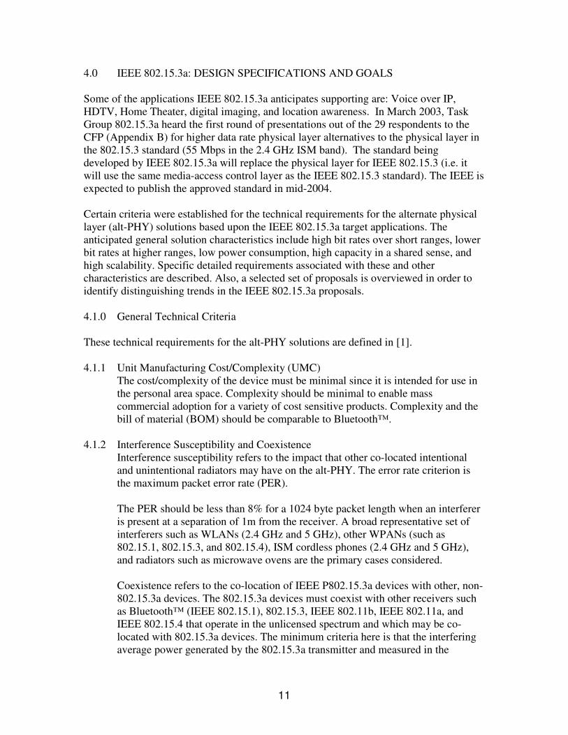
4.0 IEEE 802.15.3a: DESIGN SPECIFICATIONS AND GOALS Some of the applications IEEE 802.15.3a anticipates supporting are: Voice over IP, HDTV, Home Theater, digital imaging, and location awareness. In March 2003, Task Group 802.15.3a heard the first round of presentations out of the 29 respondents to the CFP (Appendix B) for higher data rate physical layer alternatives to the physical layer in the 802.15.3 standard (55 Mbps in the 2.4 GHz ISM band). The standard being developed by IEEE 802.15.3a will replace the physical layer for IEEE 802.15.3 (i.e. it will use the same media-access control layer as the IEEE 802.15.3 standard). The IEEE is expected to publish the approved standard in mid-2004. Certain criteria were established for the technical requirements for the alternate physical layer (alt-PHY) solutions based upon the IEEE 802.15.3a target applications. The anticipated general solution characteristics include high bit rates over short ranges, lower bit rates at higher ranges, low power consumption, high capacity in a shared sense, and high scalability. Specific detailed requirements associated with these and other characteristics are described. Also, a selected set of proposals is overviewed in order to identify distinguishing trends in the IEEE 802.15.3a proposals. 4.1.0 General Technical Criteria These technical requirements for the alt-PHY solutions are defined in [1]. 4.1.1 Unit Manufacturing Cost/Complexity (UMC)
The cost/complexity of the device must be minimal since it is intended for use in the personal area space. Complexity should be minimal to enable mass commercial adoption for a variety of cost sensitive products. Complexity and the bill of material (BOM) should be comparable to Bluetooth™.
4.1.2 Interference Susceptibility and Coexistence
Interference susceptibility refers to the impact that other co-located intentional and unintentional radiators may have on the alt-PHY. The error rate criterion is the maximum packet error rate (PER).
The PER should be less than 8% for a 1024 byte packet length when an interferer is present at a separation of 1m from the receiver. A broad representative set of interferers such as WLANs (2.4 GHz and 5 GHz), other WPANs (such as 802.15.1, 802.15.3, and 802.15.4), ISM cordless phones (2.4 GHz and 5 GHz), and radiators such as microwave ovens are the primary cases considered.
Coexistence refers to the co-location of IEEE P802.15.3a devices with other, non-802.15.3a devices. The 802.15.3a devices must coexist with other receivers such as Bluetooth™ (IEEE 802.15.1), 802.15.3, IEEE 802.11b, IEEE 802.11a, and IEEE 802.15.4 that operate in the unlicensed spectrum and which may be co-located with 802.15.3a devices. The minimum criteria here is that the interfering average power generated by the 802.15.3a transmitter and measured in the
12
relevant bandwidth of the victim receiver should be at least 6 dB below the minimum sensitivity level of the non-802.15.3a device operating in the 6 Mbps mode, when the separation between the 802.15.3a transmitter and victim receiver is 1 m.
4.1.3 Technical Feasibility – Manufacturability and Time to Market
The proposed alt-PHY should be feasible in the sense that the manufacturing process should have an effective mass production capability. Also, a short time to market is extremely desirable.
4.1.4 Regulatory Impact
Because of the different spectral allocations in different geopolitical regions, the proposed alt-PHY should be adaptable to various regulatory restrictions (such as those in the United States, European countries, and Japan).
4.1.5 Scalability
Scalability parameters include; power consumption, payload bit rate and data throughput measured at the PHY-service access point (PHY-SAP), channelization (physical or coding), complexity, range, frequencies of operation, occupied bandwidth of operation, and other functions deemed appropriate. The alt-PHY should scale up to 480 Mbps and beyond, as well as 110Mbps and below. The MAC should be able to support the scaling of the alt-PHY.
4.1.6 Location Awareness
Location awareness improves the usability of portable devices. A specific device can be located and identified amongst users in crowded environments. This greatly simplifies device registration in ad-hoc networks. Provisions must be made to propagate location information to a suitable management entity.
4.2.0 Physical Layer Selection Criteria The down-selection process, which will begin after the third round of proposal presentations (Appendix B), will use these selection criteria (defined in [21]) to select a candidate proposal for drafting. 4.2.1 Size and Form Factor
The device should be compact and easy to integrate into consumer devices, especially portable ones. The PHY components should be capable of fitting into a form factor consistent with that of hand-held devices and storage mediums.
4.2.2 Simultaneously Operating Piconets
The proposed PHY should operate in the close proximity of multiple uncoordinated piconets, at bit rates of 110 Mbps, 200 Mbps and the optional 480 Mbps. A minimum of 200 packets should be used in estimating the packet error rate.

13
4.2.3 Signal Acquisition The signal acquisition methods are the techniques by which the proposed receiver acquires and tracks the incoming signal in order to correctly receive the transmitted data. Target acquisition times are less than 6 µs for piconet clear channel assessment (CCA) (referenced to the beginning of the preamble), and less than 20µs for acquisition from the beginning of the preamble to the beginning of the header.
4.2.4 Power Management Modes:
The ability to reduce power consumption for consumer electronic devices is important to enable battery operated devices. The alt-PHY should consume less than 100 mW for 110 Mbps and less than 250 mW for 200 Mbps in either the transmit state or the receive state. The 802.15.3a standard should also provide power management capabilities such as device sleep, wakeup, poll, power save etc.
4.2.5 Antenna Practicality
The antenna size and form factor should be consistent with a small form factor without deviating significantly from the original device size. That is, the antenna size should be comparable to the 802.15.3a device.
The antenna form factor should be consistent with the following form factors:
- PC Card - Compact Flash - Memory Stick - SD Memory
A summary of these technical requirements and selection criteria developed by the 802.15.3a task group are included in Appendix D: 4.3 Proposals Overview This section will analyze the proposals from 3 of the 29 companies that have responded to the CFP (Appendix B) as of March 2003. These proposals were chosen because they provide distinct examples of some of the unique design choices made by the proposers. This discussion will identify these design choices and the larger implications of these choices. An extensive collection of proposal overviews (of the same form as Table 3) can be found in Appendix E. Company Texas Instruments Spectrum Allocation: # of bands 3 (additional bands can be added in the future) Bandwidths 503.25 MHz Frequency ranges 3.168 GHz – 4.752 GHz Modulation Scheme TFI-OFDM, QPSK

14
Coexistence method null band for WLAN (~5 GHz) Multiple access method not available # of simultaneous piconets not available Error correction codes Convolutional code Code rates 11/32 @ 110 Mbps, 5/8 @ 200 Mbps, ¾ @ 480 Mbps Link margin 5.5 dB @ 10 m @ 110 Mbps,
10.2 dB @ 4 m @ 200 Mbps, 12.2 dB @ 2 m @ 480 Mbps
Symbol period 312.5 ns OFDM symbol Multipath mitigation method 1-tap (robust to 60.6 ns delay spread)
Table 4: Overview of the TI Physical Layer Proposal for IEEE 802.15.3a [22]. As shown in Table 3, Texas Instruments chose to implement a multibanded UWB system. In [22], the authors argue that, due to path loss, attenuation, and losses in current RF technology, the use of the frequency bands above 5 GHz only yields minor improvements in capacity at the cost of increased receiver complexity. For this reason, Texas Instruments chose to use only 3 bands located below the 5 GHz ISM band for their implementation. Each band uses orthogonal frequency division multiplexing (OFDM) which allows for each UWB band to be divided into a set of orthogonal narrowband channels (with much larger symbol period duration). Because of the increased length of the OFDM symbol period, this modulation method can successfully reduce the effects of ISI. However, this robust multipath tolerance comes at the price of increased transceiver complexity, the need to combat inner carrier interference (ICI), and tighter linear constraint on amplifying circuit elements. Company XtremeSpectrum Spectrum Allocation: # of bands 2 Bandwidths 1.368 GHz, 2.736 GHz Frequency ranges 3.1 GHz – 5.15 GHz,
5.825 GHz – 10.6 GHz Modulation Scheme BPSK, QPSK Coexistence method null band for WLAN (~5 GHz) Multiple access method Avoidance # of simultaneous piconets Ternary CDMA Error correction codes Convolutional code, Reed-Soloman code Code rates ½ @ 110 Mbps, RS(255,223) @ 200 Mbps,
RS(255,223) @ 480 Mbps Link margin 9.9 dB @ 10 m @ 110 Mbps,
13.2 dB @ 4 m @ 200 Mbps, 3.4 dB @ 2 m @ 600 Mbps
Chip duration 731 ps (Low band), 365.5 ps (High band) Multipath mitigation method Decision feedback equalizer
Table 5: Overview of the XtremeSpectrum CFP Document [23].
15
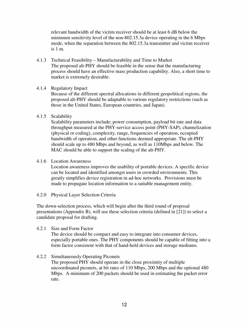
The XtremeSpectrum proposal shows a dual band approach. Table 4 shows that each of the bands in this company’s proposal employs short duration pulses to transmit over bandwidths in excess of 1 GHz (as in impulse radio). The comparison of impulse radio and multibanded UWB in Section 3 of this document can be directly applied to a comparison between the XtremeSpectrum and Texas Instruments proposals. Such an application of the analysis would show that there are distinct trade-offs between transceiver complexity and multipath resolution, linearity requirements, peak-to-average power ratio, and in various other aspects of the transceiver design. The final proposal overviewed in this section compromises between the two previous proposals. Intel has proposed an architecture which employs multiband UWB with 7 bands (see Table 5), and it also uses impulse radio within each band. Since Intel does not use OFDM as its modulation scheme, it suffers from more susceptibility to multipath. In comparison to Texas Instruments’ architecture, Intel’s multiband approach trades off complexity in its modulation scheme for added complexity in its equalizer. Company Intel Spectrum Allocation: # of bands 7 (+ optional 6 bands for future use) Bandwidths 550 MHz Frequency ranges 3.6 GHz – 6.9 GHz, (7.45 GHz – 10.2 GHz optional) Modulation Scheme M-ary Bi-orthogonal Keying, QPSK Coexistence method null band for WLAN (~5 GHz) Multiple access method DS/FH CDMA, optional FDMA # of simultaneous piconets not available Error correction codes Convolutional code, Reed-Soloman code Code rates 6/32 @ 110 Mbps, 5/16 @ 200 Mbps, ¾ @ 480 Mbps Link margin 6.3 dB @ 10 m @ 108 Mbps,
8.0 dB @ 4 m @ 288 Mbps, 4.0 dB @ 4 m @ 577 Mbps
Symbol period 3 ns Multipath mitigation method frequency interleaving of MBOK chips; time frequency
codes; feed forward filter Table 6: Overview of the Intel CFP Presentation for a UWB PHY [24].
There are many combinations of spectral allocations, modulation methods, and other design parameters used throughout the proposals. The trade-offs and design issues that have been discussed throughout this document can be used to identify the benefits and costs of each set of design choices listed in the proposal overviews in Appendix E.

16
5.0 CONCLUSION In this paper, tremendous capacity over short distances was identified as the major impetus for UWB communication. This driving factor and the FCC approval of UWB for commercial use prompted IEEE 802.15.3a standards proposers to consider UWB as a viable physical layer alternative for very high data rates in WPANs. In order to communicate over the typical environment for a WPAN device (i.e. the indoor fading channel), Section 2 showed that accurate channel models are necessary. Though there is still ongoing work to model the indoor wireless channel, there are some proposed channel models which closely fit measured data (namely Intel’s modified S-V model). The multipath effects of an indoor channel impact the multibanded approach to UWB less severely than an impulse radio approach to UWB, as described in Section 3. The multibanded approach to UWB has multiple degrees of freedom over the impulse based approach [19], which can be exploited in order to reduce receiver complexity. Because of its flexibility and more conventional implementation in CMOS technology, many companies presenting 802.15.3a proposals favor the multibanded approach to UWB. The design choices described in the last section should be an indicator to the reader of the multitude of design trade-offs facing standards makers in TG3a. It will be a difficult task to find a single proposal which will optimally meet all of the requirements set forth in [1]. The successful commercialization of UWB technology depends on the success of IEEE 802.15.3a in developing a flexible and cost effective standard that can easily be deployed to deliver high data rate applications to WPAN devices.

17
REFERENCES [1] Ellis, Siwiak, Roberts, “TG3a Technical Requirements,” IEEE 802.15-03/030r0.
December 27, 2002. [2] FCC, First Report and Order 02-48. February 2002. [3] A. F. Molish, J. Zhang, “Ultra Wideband Systems,”
http://www.wmrc.com/businessbriefing/pdf/wireless_2003/Publication/molisch.pdf. Last accessed May 5, 2003.
[4] W. M. Lovelace and J. K. Townsend, “The Effects of Timing Jitter and Tracking on the Performance of Impulse Radio,” in IEEE Journal on Selected Areas in Communications, vol. 20 no. 9, pages 251-254, December 2002.
[5] 802.11Hotspots.com. http://www.multispectral.com/history.html. Last accessed April 24, 2003.
[6] R. F. Heile, “TG3a Project Timeline,” IEEE 802.15-03/056r0. January, 2003. [7] D. Cassioli, M. Z. Win, and A. F. Molisch, “The Ultra-Wide Bandwidth Indoor
Channel: from Statistical Model to Simulations,” IEEE P802.15-02/284-SG3a. September 4, 2002.
[8] J. Foerster and Q. Li, “UWB Channel Modeling Contribution from Intel,” IEEE P802.15- 02/279-SG3a. September 4, 2002.
[9] M. Pendergrass, “Empirically Based Statistical Ultra-Wideband Channel Model,” IEEE P802.15-02/240-SG3a. September 4, 2002.
[10] J. Kunisch and J. Pamp, “Radio Channel Model for Indoor UWB WPAN Environments,” IEEE P802.15-02/281-SG3a. September 4, 2002.
[11] J. Foerster, “Channel Modeling Sub-committee Report,” IEEE P802.15-02/368r1-SG3a. November 5, 2002.
[12] A. Saleh and R. Valenzuela, “A Statistical Model for Indoor Multipath Propagation,” IEEE JSAC, Vol. SAC-5, No. 2, Feb. 1987, pp. 128-137.
[13] Q. H. Spencer, B. D. Jeffs, M. A. Jense, A. L. Swindlehurst, "Modeling the Statistical Time and Angle of Arrival Characteristics of an Indoor Multipath Channel," IEEE JSAC, Vol. 18, No. 3, March 2000.
[14] T. S. Rappaport and S. Sandhu, “Radio-Wave Propagation for Emerging Wireless Personal Communication Systems,” IEEE Antennas and Propagation Magazine, Vol. 36, No. 5, pg. 14-24, Oct. 1994
[15] H. Hashemi, “Impulse Response Modeling of Indoor Radio Propagation Channels,” IEEE JSAC, Vol. 11, No. 7, Sept. 1993, pp. 967-978.
[16] M. Z. Win and R. A. Scholtz, “Impulse Radio: How it Works” IEEE Communications Letters, Vo. 2, No.2, p. 36, February 1998.
[17] http://grouper.ieee.org/groups/802/15/pub/2003/Mar03/. Last accessed May 5, 2002. [18] M. Pendergrass, Time Domain Corporation, “Time Domain Supporting Text for
802.15.3 Alternate Physical Layer Proposal,” IEEE 802.15-03/144r1. March 3, 2003.
[19] Somayazulu, Foerster, and Roy, “Design Challenges for Very High Data Rate UWB Systems,” Intel Labs, http://www.intel.com/technology/ultrawideband/ downloads/Asilomar_2002_final.pdf. Last accessed May 5, 2003.
[20] T. S. Rappaport, Wireless Communications. Prentice Hall. December 2001.

18
[21] Ellis, Siwiak, Roberts, “P802.15.3a Alt PHY Selection Criteria,” IEEE 802.15-
03/031r9. March 13, 2003. [22] A. Batra, et. al. “TI Physical Layer Proposal for IEEE 802.15 Task Group 3a,”
IEEE P802.15-03/142r0. March 3, 2003. [23] R. Roberts, “XtremeSpectrum CFP Document,” IEEE P802.15-03/154r1. March
3, 2003. [24] J. Foerster, V. Somayazulu, S. Roy, et. al., “Intel CFP Presentation for a UWB
PHY,” IEEE P802.15-03/109r1. March 3, 2003.
19
APPENDIX A – Data Rate Requirement for Various WPAN Applications This appendix provides a detailed description of the data rate requirements of some emerging and existing applications in the WPAN space (a range of less than 10 meters). These tables are from [1], a document released by IEEE 802.15.3a. H.323 / T.120 Video Conferencing
Application Ingredients
Data Format Min Data Rate Max Data Rate
Video Camera MPEG2 resolution w/o compression
75Mbps 150Mbps
Monitor Varying compression 63Mbps 1Gb/s H.323 comm (broadband)
H.261/H.263, G.711/G.723, T.120
128kb/s 10Mbps
Audio (mono) PCM 64kb/s 64kb/s Mass storage 50Mbps 240 Mbps Mouse < 9600 b/s < 9600 b/s Keyboard < 9600 b/s < 9600 b/s Total 188+ Mbps 1.4+ Gb/s
Home Theater
Application Ingredients
Data Format Min Data Rate Max Data Rate
Monitor/Projector HD Video 19.2 Mbps 19.2 Mbps Audio (speakers) 5.1 to 10.2 channels (24 bits) 13.8 Mbps 27.6 Mbps Web Pad Internet (streaming media) 10 Mbps 10 Mbps Remote Controller ?? ?? Total 43 Mbps 56.8 Mbps
Interactive Applications
Application Ingredients
Data Format Min Data Rate Max Data Rate
Monitor/Projector XGA w/ Varying compression
63 Mbps 1 Gb/s
Audio (speakers) 5.1 to 10.2 channels (24 bits)
13.8 Mbps 27.6 Mbps
Interactive controller
(Reaction Sensitive) ?? ??
Total
Content Downloading
Content Downloaded
Data Format Data Rate Transfer Time
Audio MP3 60 Mbps 10 sec CD 90 Mbps 60 sec Photos Varied Compression 90 Mbps 10 sec Movies DV ?? (higher) ?? Total
20
APPENDIX B – IEEE 802.15.3a Timeline
2003
J J A S O N D J F M A M J J DJ F M A M A S O N
Downselect
2002
CFA
D
DraftProject Definition
FCC approves UWB3 rounds ofproposals
Selection Criteriaestablished
Technical Requirementsapproved
CFI/CFP
Complete drafting,Begin voting
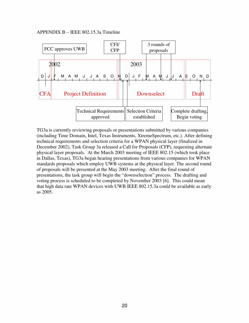
TG3a is currently reviewing proposals or presentations submitted by various companies (including Time Domain, Intel, Texas Instruments, XtremeSpectrum, etc.). After defining technical requirements and selection criteria for a WPAN physical layer (finalized in December 2002), Task Group 3a released a Call for Proposals (CFP), requesting alternate physical layer proposals. At the March 2003 meeting of IEEE 802.15 (which took place in Dallas, Texas), TG3a began hearing presentations from various companies for WPAN standards proposals which employ UWB systems at the physical layer. The second round of proposals will be presented at the May 2003 meeting. After the final round of presentations, the task group will begin the “downselection” process. The drafting and voting process is scheduled to be completed by November 2003 [6]. This could mean that high data rate WPAN devices with UWB IEEE 802.15.3a could be available as early as 2005.
21
APPENDIX C – Saleh-Valenzuela Model [8]
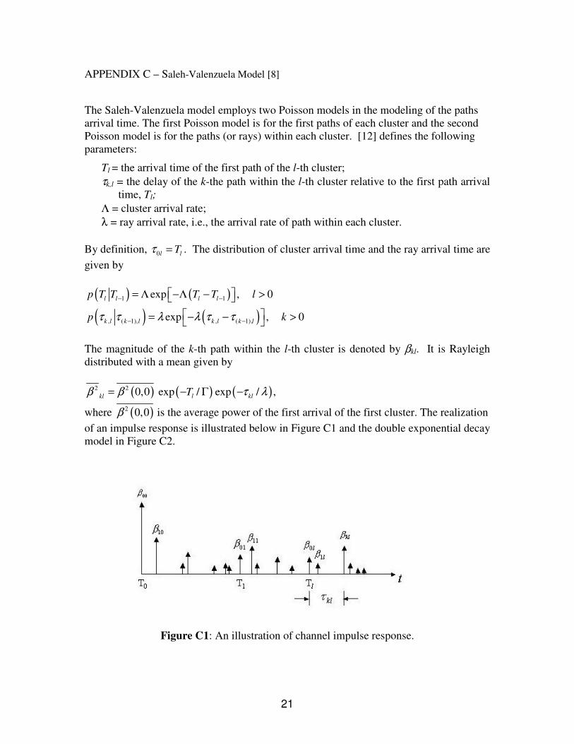
The Saleh-Valenzuela model employs two Poisson models in the modeling of the paths arrival time. The first Poisson model is for the first paths of each cluster and the second Poisson model is for the paths (or rays) within each cluster. [12] defines the following parameters:
Tl = the arrival time of the first path of the l-th cluster; τk,l = the delay of the k-the path within the l-th cluster relative to the first path arrival
time, Tl; Λ = cluster arrival rate; λ = ray arrival rate, i.e., the arrival rate of path within each cluster.
By definition, 0l lTτ = . The distribution of cluster arrival time and the ray arrival time are given by
( ) ( )( ) ( )
1 1
, ( 1), , ( 1),
exp , 0
exp , 0
l l l l
k l k l k l k l
p T T T T l
p kτ τ λ λ τ τ
− −
− −
� �= Λ −Λ − >� �
� �= − − >� �
The magnitude of the k-th path within the l-th cluster is denoted by βkl. It is Rayleigh distributed with a mean given by
( ) ( ) ( )2 2 0,0 exp / exp / ,l klkl Tβ β τ λ= − Γ −
where ( )2 0,0β is the average power of the first arrival of the first cluster. The realization of an impulse response is illustrated below in Figure C1 and the double exponential decay model in Figure C2.
Figure C1: An illustration of channel impulse response.

22
Figure C2: An illustration of double exponential decay (copied from [13]).
23
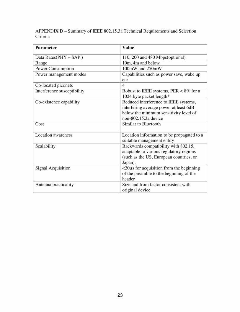
APPENDIX D – Summary of IEEE 802.15.3a Technical Requirements and Selection Criteria Parameter Value
Data Rates(PHY – SAP ) 110, 200 and 480 Mbps(optional) Range 10m, 4m and below Power Consumption 100mW and 250mW Power management modes Capabilities such as power save, wake up
etc Co-located piconets 4 Interference susceptibility Robust to IEEE systems, PER < 8% for a
1024 byte packet length* Co-existence capability Reduced interference to IEEE systems,
interfering average power at least 6dB below the minimum sensitivity level of non-802.15.3a device
Cost
Similar to Bluetooth
Location awareness Location information to be propagated to a suitable management entity
Scalability Backwards compatibility with 802.15, adaptable to various regulatory regions (such as the US, European countries, or Japan).
Signal Acquisition <20µs for acquisition from the beginning of the preamble to the beginning of the header
Antenna practicality Size and from factor consistent with original device

24
APPENDIX E – Proposal Overview This Appendix provides an overview of the current proposals being presented to IEEE 802.15.3a for consideration as of March 2003. Company Texas Instruments Spectrum Allocation: # of bands 3 (additional bands can be added in the future) Bandwidths 503.25 MHz Frequency ranges 3.168 GHz – 4.752 GHz Modulation Scheme TFI-OFDM, QPSK Coexistence method null band for WLAN (~5 GHz) Multiple access method not available # of simultaneous piconets not available Error correction codes Convolutional code Code rates 11/32 @ 110 Mbps, 5/8 @ 200 Mbps, ¾ @ 480 Mbps Link margin 5.5 dB @ 10 m @ 110 Mbps,
10.2 dB @ 4 m @ 200 Mbps, 12.2 dB @ 2 m @ 480 Mbps
Symbol period 312.5 ns OFDM symbol Multipath mitigation method 1-tap (robust to 60.6 ns delay spread) A. Batra, et. al. “TI Physical Layer Proposal for IEEE 802.15 Task Group 3a,” IEEE P802.15-03/142r0. March 3, 2003. Company XtremeSpectrum Spectrum Allocation: # of bands 2 Bandwidths 1.368 GHz, 2.736 GHz Frequency ranges 3.1 GHz – 5.15 GHz, 5.825 GHz – 10.6 GHz Modulation Scheme BPSK, QPSK Coexistence method null band for WLAN (~5 GHz) Multiple access method Ternary CDMA # of simultaneous piconets 4 piconets/band Error correction codes Convolutional code, Reed-Soloman code Code rates ½ @ 110 Mbps, RS(255,223) @ 200 Mbps,
RS(255,223) @ 480 Mbps Link margin 9.9 dB @ 10 m @ 110 Mbps,
13.2 dB @ 4 m @ 200 Mbps, 3.4 dB @ 2 m @ 600 Mbps
Chip duration 731 ps (Low band), 365.5 ps (High band) Multipath mitigation method Decision feedback equalizer R. Roberts, “XtremeSpectrum CFP Document,” IEEE P802.15-03/154r1. March 3, 2003.

25
Company Intel Spectrum Allocation: # of bands 7 (+ optional 6 bands for future use) Bandwidths 550 MHz Frequency ranges 3.6 GHz – 6.9 GHz, (7.45 GHz – 10.2 GHz optional) Modulation Scheme M-ary Bi-orthogonal Keying, QPSK Coexistence method null band for WLAN (~5 GHz) Multiple access method DS/FH CDMA, optional FDMA # of simultaneous piconets not available Error correction codes Convolutional code, Reed-Soloman code Code rates 6/32 @ 110 Mbps, 5/16 @ 200 Mbps, ¾ @ 480 Mbps Link margin 6.3 dB @ 10 m @ 108 Mbps,
8.0 dB @ 4 m @ 288 Mbps, 4.0 dB @ 4 m @ 577 Mbps
Symbol period 3 ns Multipath mitigation method frequency interleaving of MBOK chips; time frequency
codes; feed forward filter J. Foerster, V. Somayazulu, S. Roy, et. al., “Intel CFP Presentation for a UWB PHY,” IEEE 802.15-03/109r1. March 3, 2003. Company Time Domain Spectrum Allocation: # of bands 15 Bandwidths 520 MHz Frequency ranges 3.236 GHz – 10.311 GHz Modulation Scheme BPSK, QPSK, FH-SS Coexistence method sacrifice 1 band for WLAN coexistence (~5 GHz) Multiple access method TFMA, FDMA # of simultaneous piconets 6 Error correction codes Convolutional code Code rates ½ @ 110 Mbps, ¾ @ 200 Mbps, 1/1 @ 480 Mbps Link margin 3.50 dB @ 10 m @ 110 Mbps,
8.20 dB @ 4 m @ 200 Mbps, 6.41 dB @ 2 m @ 480 Mbps
Chip duration 3.89 ns Multipath mitigation method 1or 2-finger Rake, Viterbi decoder J. Kelly, “Time Domain’s Proposal for UWB Multi-band Alternate Physical Layer for 802.15.3a,” IEEE 802.15-03/143r2. March 8, 2003.

26
Company Pulse Link Spectrum Allocation: # of bands 1 Mandatory + 1 Optional Bandwidths 1.45 GHz Frequency ranges 3.115 GHz – 4.656 GHz, 6.475 GHz – 7.925 GHz Modulation Scheme Ternary (2nd order OFDM and Walsh codes) Coexistence method Avoidance Multiple access method not available # of simultaneous piconets not available Error correction codes Convolutional code Code rates ¾ Link margin 2.5 dB @ 10 m @ 110 Mbps,
2.6 dB @ 7 m @ 200 Mbps, 2.5 dB @ 5 m @ 480 Mbps
Symbol period 11.1 ns @ 110 Mbps, 5.6 ns @ 200 Mbps, 2.8 ns @ 480 Mbps
Multipath mitigation method not available Y. Bahreini, J. Santhoff, “Alternate PHY Proposal for High Rate 802.15.3 Draft Standard,” IEEE 802.15-03/127r0. March 2, 2003. Company Sony Spectrum Allocation: # of bands 3 Bandwidths 1.8 GHz Frequency ranges 3.1 GHz – 4.9 GHz, 6.1 GHz – 7.9 GHz,
8.1 GHz – 9.9 GHz Modulation Scheme DS-SS, BPSK Coexistence method avoidance Multiple access method FDMA, CDMA # of simultaneous piconets not available Error correction codes Convolutional code Code rates ½ @ 110 Mbps Link margin 2.35 dB @ 10 m @ 110 Mbps,
3.06 dB @ 4 m @ 200 Mbps, 2.57 dB @ 2 m @ 480 Mbps
Symbol period not available Multipath mitigation method 4-finger baseband Rake receiver E. Fujita, K. Watanabe, K. Tanaka, et. al., “Sony CFP Presentation,” IEEE 802.15-03/137r1. March 20, 2003.

27
Company Discrete Time Spectrum Allocation: # of bands 15 bands Bandwidths 500 MHz Frequency ranges 3.1 GHz – 10.6 GHz, Modulation Scheme QPSK, FH Coexistence method sacrifice 2 band for WLAN coexistence (5 GHz) Multiple access method FDMA # of simultaneous piconets not available Error correction codes Convolutional code Code rates ½ @ 110 Mbps Link margin 15.1 dB @ 4m @ 110 Mbps,
12 dB @ 4 m @ 220 Mbps, 11.1 dB @ 4 m @ 480 Mbps
Symbol period 8.9 ns @ 110 Mbps, 4.5 ns @ 200 Mbps, 2.1 ns @ 480 Mbps
Multipath mitigation method not available Roberto Aiello, “Discrete Time PHY Proposal for TG3a,” IEEE 802.15-03/099r1. March 2003. Company Mitsubishi Spectrum Allocation: # of bands 1 Bandwidths 6.6 GHz Frequency ranges 4 GHz – 10.6 GHz Modulation Scheme BPSK Coexistence method not available Multiple access method PPM and polarity hopping # of simultaneous piconets 4 Error correction codes Convolutional code Code rates ½ @ 200 Mbps Link margin 3 dB @ 10 m @ 200 Mbps Symbol period 4.5 ns @ 200 Mbps Multipath mitigation method Rake receiver, MMSE equalizer A. F. Molisch et al., “Mitubishi Electric Proposal Time-Hopping Impulse Radio,” IEEE 802.15-03/111r0. March 3, 2003.

28
Company Philips Spectrum Allocation: # of bands 4 – 10, 6 (110 Mbps, 200 Mbps) , 8 (480 Mbps) Bandwidths not available Frequency ranges 2 GHz – 6 GHz Modulation Scheme Spectral Keying Coexistence method avoidance Multiple access method not available # of simultaneous piconets 4 Error correction codes Convolutional code Code rates Parallel concatenated convolution turbo code Link margin not available Chip period 9.1 ns @ 110 Mbps, 4.5 ns @ 200 Mbps,
4.5 ns @ 480 Mbps Multipath mitigation method Rake receiver C. Razzell, “Philips TG3a CFP Presentation,” IEEE 802.15-03/125r2. March 2003. Company Focus Enhancements Spectrum Allocation: # of bands 1 Bandwidths 2.9 GHz Frequency ranges 3.4 GHz – 6.36 GHz Modulation Scheme FM-OFDM, 8-ary PSK Coexistence method null subcarrier for WLAN (~5 GHz) Multiple access method not available # of simultaneous piconets not available Error correction codes Convolutional code Code rates 2/3 @ 110 Mbps Link margin not available Symbol period 10 ns @ 110 Mbps Multipath mitigation method PolyPhase Receiver K. A. Boehlke, “P802.15 Alt PHY using FM-OFDM,” IEEE 802.15-03/103r0. March 3, 2003.