the emonator: a novel musical interface
TRANSCRIPT

The Emonator: A Novel Musical Interfaceby
Daniel James Overholt
B.A., Music
B.S. Computer Engineering
California State University, Chico (1997)
Submitted to the Program in Media Arts and Sciences,
School of Architecture and Planning
in Partial Fulfillment of the Requirements for the Degree of
Master of Science in Media Arts and Sciences
at the
Massachusetts Institute of Technology
Sept, 2000
Copyright 2000 Massachusetts Institute of Technology
All rights reserved.
Signature of Author Program in MediaA ts and SciencesAug 17, 2000
MASSACHUSETTS INSTITUTE
MASSACHUSETTS INSTITUTEOF TECHNOLOGY
OrT 9 0 ?000
LIBRARIES
Chair
7') Tod MachoverAssociate Profess o 3dia Arts and Sciences
MIT Media Laboratory
Stephen A. BentonDepartmental Committee on Graduate Students
Program in Media Arts and Sciences
Certified by
Accepted by
/11

2

The Emonator: A Novel Musical Interface
by
Daniel James Overholt
Submitted to the Program in Media Arts and Sciences,School of Architecture and Planning on Aug , 2000
in Partial Fulfillment of the Requirements for the Degree ofMaster of Science at the Massachusetts Institute of Technology
Abstract
This thesis will discuss the technical and artistic design of the Emonator', anovel interactive musical interface which responds to gestural input with real-time aural and visual feedback. A user interacts with the Emonator bymanipulating the surface formed by a bed of rods at the top of the Emonator. The
user's movements are analyzed and used to control several music and soundgeneration engines as well as video streams in real-time. The Emonator is aninteresting musical experience for both amateur and professional musicians. It isalso versatile, working well as a stand-alone interface or as part of a largerinteractive experience.
Thesis Supervisor: Tod MachoverTitle: Associate Professor of Media Arts and Sciences
1 Emo-nator \e-'mO nAtor\ n An innovative hypermedia performance instrument.
-3-

-4-

The Emonator: A Novel Musical Interface
by
Daniel James Overholt
The following people have served as readers for this thesis:
Reader:Joseph Paradiso
Principal Research ScientistMIT Media Laboratory
Glorianna DavenportPrincipal Research Associate
MIT Media Laboratory
Reader:
-5-

-6-

Table of Contents
1 Introduction 13
1.1 Motivation 13
1.2 The Emonator 15
1.3 Background and Review of Research Activities 16
1.3.1 Electronic Instruments and Interactive Computer Music 17
1.3.2 Previous Work from the Media Laboratory and Industry 20
1.4 Fundamental Hypotheses 21
1.5 Organization of this Thesis 21
2 The Emonator System 23
2.1 Design Criteria 23
2.2 Hardware Design Decisions 23
2.3 Equipment 26
2.3.1 Operational Equipment 26
2.3.2 Aesthetic Equipment 27
3 Emonator Implementation: Technical and Artistic Issues 29
3.1 Technical Design in an Artistic Context 29
3.1.1 Mechanical Design 29
3.1.2 Sensor Architecture Design 31
3.1.3 System Logic Design 36
3.2 Software Implementation 38
3.2.1 Software Tools Used 39
MIDI 39
MaxIMSP 40
SuperCollider 40
Open Sound Control 41
QuickTime for Java 41
3.2.2 Testing Applications 41
3.2.3 Audio Applications 42
Low-level Interaction 43
Medium-level Interaction 44
-7-

High-level Interaction 46
Remote and Distributed Operation 47
3.2.4 Visual Applications 48
4 Results, Observations, and Future Directions 49
4.1 Observation of the Emonator in Use 49
4.1.1 Preliminary Emonator Testing 50
4.1.2 The Emonator Demonstration in Ireland 50
4.2 Critical Evaluation of the Emonator 52
4.2.1 Strengths of the Emonator System 53
4.2.2 Weaknesses of the Emonator System 54
4.3 Future Directions for Applications and Research 55
4.3.1 Signal Processing Extensions to the Emonator 55
4.3.2 Learning Systems, Musical Intention, and Interactive Systems _ 56
4.3.3 Visual Enhancements to the Emonator System 57
4.3.4 Beyond the Emonator 58
5 Conclusions 61
5.1 Synopsis of the Emonator 61
A FPGA Code Snippet-Top File of the Hierarchy 63
-8-

List of Figures and Tables
1.1 The Emonator 16
1.2 Part of the Score for Karlheinz Stockhausen's 'Studie I' 19
2.1 Opto-electronic Sensing Architecture 24
2.2 Photo of Emonator Optics Board 25
2.3 Block Diagram of the Emonator System 26
2.4 Emonator Equipment List 26
2.5 Half-Scale Model of Table Design 28
3.1 Moire pattern on Emonator Rod 30
3.2 Optics Holders made of Acrylic 31
3.3 Diagram of a Quadrature Waveform. 32
3.4 Schematic Diagram of the Emonator Motherboard. 33
3.5 PCB Layout of the Emonator Motherboard. 34
3.6 PCB Layout of the Emonator Optics Board 35
3.7 Emonator Components 36
3.8 Photo of the Emonator Motherboard.___________________ 38
3.9 The Emonator Testing Application ____________________42
3. 10 Emonator Low-level Additive Synthesis in Max!MSP ____________44
3.11 Vocalator Medium-level Application in SuperCollider _____________45
3.12 Rhythmator High-level Application in Max ________________46
3.13 Emonator Video Collage Application ___________________48
4.1 The Emonator Being Played by a New User ________________49
4.2 Diagram of the Demonstration Setup in Ireland _ _____________51
4.3 Setup of the Ireland Demonstration ____________________52
4.4 Visualization of a Future Graphic Display _________________57
4.5 Real-time Graphics Generated by SuperCollider ______________58
-9-

-10-

Acknowledgements
I have had a amazing experience here in the stimulating environment of the Media Lab-
Thanks to all of my great friends, colleagues, and professors who have taught me so much about life.
I would like to thank,
Tod Machover, for his guidance, vision, and encouragement which led to the Emonator, and providing me
with resources to pursue my work.
Glorianna Davenport, for being so supportive at all the hard times, and being patient with me.
Joe Paradiso, for his encouragement, and amazing knowledge.
Tristan Jehan, for his work with Max, Open Sound Control, and SuperCollider.
Paul Nemirovsky, for his interesting conversations, and Lingo hacking skills.
Andrew Yip, for working on software for the Emonator, and being one of the coolest UROPs out there.
All of the Hyperinstrument Group graduate students and UROPs.
Ali Mazalek, for being there when I need it most, and putting up with me.
And most of all, my family. Without your support and love I would never make it.
- 11 -

- 12 -

Chapter 1
Introduction
1.1 Motivation
Everyone enjoys listening to music, and many of us aspire to contribute to the process. But how
can we express ourselves musically without first spending years learning how to play an
instrument? For those among us who are already musicians, how can we gain additional control
over the music we play in order to be more expressive? The goal of this work is to develop the
Emonator, a musical instrument for amateurs and professionals alike. My hypothesis is that by
creating a tactile gestural interface to control a multi-functional musical instrument, a whole new
class of musical instruments evolves: the Emonator is a versatile controller that can easily adapt
to new tasks and to the skills of individual performers (from novices to experts) in a variety of
different environments. It provides the performer with a sculptable 3D surface to control music
and visuals through a matrix of push rods.
The human hand has shaped and produced many amazing things over the centuries-it is one of
the most nimble and dexterous tools at our disposal. Hundreds, if not thousands of musical
instruments have been developed that are played with the hand, and one of the goals of the
Emonator is to create an interface that will make the most of our skills with our hands. There are
several ways in which the Emonator is optimized in this respect-the most obvious being the
physical size and shape of the interface, which is based around the structure of the hand. The
design allows for a variety of interaction techniques, ranging from the smooth, wave-like
continuous control of the surface formed by the Emonator's rods (using the open palm and
fingers), to the individual control of single rods (or a groups of rods) using the fingertips. In
- 13 -

order to provide these different levels of control, it was necessary to construct an interface with
multiple points of interaction. This requirement led to a design that uses a matrix of rods in
which each is roughly the size of a human finger, and the entire array is slightly larger than the
average hand. While there are musical controllers that provide discrete event-type data (such as
keyboards), or continuous data (such as sliders, joysticks, etc), very few of them allow control of
both. Some MIDI keyboards provide a limited amount of continuous control, but it is always
done through a disparate left-hand controller that is separate from the actual keys. The Emonator
combines these functionalities by allowing the performer to access individual parameters through
each rod, yet simultaneously shape the continuous data through the overall shape of the bed of
rods.
The Hyperinstruments and the Interactive Cinema groups at the MIT Media Laboratory are
concerned with using technology to engage people in an active role while listening to music or
watching a video. Previous work in the Hyperinstruments group using interactive computer
algorithms, computer human interfaces, and sensor technologies has led to projects such as
Singing Tree [23], the Sensor Chair [25, 26], the Melody Easel [16], and the Rhythm Tree [24].
These interfaces were developed as part of the Brain Opera [24] by Tod Machover, which was an
attempt to collectively involve large numbers of people in an active musical experience from
composition to performance. Previous work in the Interactive Cinema group includes the design
of interactive installations and computer-based applications that aim to actively engage the
audience in the co-construction of immersive visual and narrative experiences. Some examples
include projects such as Kidsroom [12], Augmented Performances [6, 20, 27], and Dream
Machine [5].
Today, most people do not play an instrument, compose, or get involved in music beyond simply
hearing it, paying as much attention to it as external circumstances permit. Those who do still
engage in music making-be it playing the violin professionally, or getting together with friends
to 'jam'-know the value of what the others are missing: experiences that are emotionally,
intellectually, and socially gratifying in the most profound sense. While it is impossible to expect
everyone to become proficient at composing music or playing an instrument, the use of
computers today as part of the "musical experience" has allowed designers to create interactive
music systems for novices. One of the areas this thesis focuses on is engaging people in a new
- 14 -

and active relationship with music that is richer than passive listening, and accessible to
everyone.
1.2 The Emonator
This thesis presents the idea of an innovative hypermedia performance instrument. It was
conceived as a collaborative project with Paul Nemirovsky from the Interactive Cinema group. In
this thesis I will explain the design and structure of the instrument, and explore three core levels
of interaction with the Emonator: high-level (affective), medium-level (timbre control), and low-
level (sonic shaping). Functionality for each level is described, and the implementation details
are explained. The intention of this multi-level approach is to allow people of varying musical
ability to actively participate in the process of making music. The implementation of the
Emonator's three levels of interaction will lead to the following scenario. A user interacts with
the Emonator by manipulating the surface formed by a bed of rods at the top of the Emonator.
The sensor architecture beneath analyzes the position of each rod, and sends it to a computer
which interprets the data as control parameters to a music generation algorithm and a video
stream. In effect, a user's gestures determine the musical and visual feedback in real-time. The
user is surrounded by a musical and visual presentation that is designed to respond to the user's
motions in an aesthetically appropriate manner.
In a larger sense, the Emonator is a physical object that acts as a means to control and manipulate
digital media. It is an attempt to design an interface which responds in real-time to the shape of a
three-dimensional surface, and interprets this in a musically meaningful way. In addition to the
musical experience, the Emonator is also an example of a human-computer interface that can
extract useful information from a human gesture by exploiting the human senses of touch and
kinesthesia. The goal is to capture the movement of the hand with as much resolution as possible,
and thus take advantage of the richness of multi-modal human senses and skills developed
through a lifetime of interaction with the physical world. Unlike many existing controllers, the
Emonator allows direct manipulation of the interface using the entire hand, as well as with the
individual fingers of one or both hands. And by using the bed of rods to provide a parallel input
- 15 -

specification for a large number of control points, the Emonator improves the communication
bandwidth with the computer, thereby giving the user a much greater potential for control.
Figure 1.1: The Emonator
1.3 Background and Review of Research Activities
In this section, particularly relevant works in the area of interactive music projects are presented.
The Emonator and its modes of interaction are innovations based on the works of many in the
fields of computer music, human-computer interaction, control systems, and audio analysis and
synthesis. The purpose is to provide an introduction to the foundation and context of this work.
Readers who wish to further research these areas are referred to the appropriate references.
- 16 -

1.3.1 Electronic Instruments and Interactive Computer Music
Beginning in 1920 with the Theremin, electronic musical instruments have become more and
more commonplace. Considered to be the first electronic instrument, the Theremin [39] (invented
by Leon Theremin) was actually more adventurous and comprehensive than most instruments
developed since. It included both a radical new interface for controlling its sound2, and a whole
new way of producing sound (by means of electronics). Since then, our ability to create, process,
and manipulate sound has developed dramatically, while interfaces to 'perform' electronic music
have progressed at a relatively slow pace. Today's commercial interfaces are most often
fashioned in the likeness of traditional instruments. This model allows musicians to apply their
technical skills to a wide variety of sound production devices, but often limits the type of musical
expressions that can be played. For example, the most ubiquitous electronic musical interface
available today is the MIDI keyboard, which is excellent for playing music written for the piano
(which it mimics). However, the interface does not provide much expressive control over notes
beyond their attack and duration (though some provide "aftertouch"), making it quite
unsatisfactory for playing most non-percussive sounds. While the Theremin does not share these
limitations with the MIDI keyboard, it requires a highly developed sense of pitch (perfect pitch),
and a very high level of muscular control in order to play it precisely. Although this is true of
many musical instruments, the Theremin was found to be particularly difficult because of the
lack of tactile feedback to the performer.
Other novel interfaces include the Radio Drum, invented by computer music pioneer Max
Mathews and engineer Bob Boie, which was used as an instrument for both amateur and
professional performers. The instrument consists of two radio batons that are actually small radio
transmitters, and a flat table-top surface with embedded receivers. Over this surface, baton
positions and velocities are tracked, and beat gestures detected; the interface has been used for
new works by composers such as Richard Boulanger at the Berklee College of Music. Max
Mathews also developed a computer-controlled analog synthesizer called GROOVE with F.
Moore while he was at AT&T Bell Laboratories in the late 1960's, which allowed a user to
2 The Theremin allows a performer to change its sound by moving their hands closer to or further from a setof antennas, one of which controls the pitch one hears, while the other controls the volume.
- 17 -

control 14 'functions of time' in real-time. These 'functions of time' are used to control
parameters of the music such as speed, volume, and waveform[ 19].
Computer Music, in the traditional sense of the term, implies that all of the music is being
generated by a computer algorithm. While the Emonator uses computer algorithms to assist users
while performing, the system is designed more as an interactive performance-driven instrument,
in which the user gets to be the composer and the performer all at once. There are many areas of
research that have combined music and technology, with some most notable examples among the
works of Max Mathews[20], Karlheinz Stockhausen[35], Pierre Boulez [18], Morton Subotnick
[36], George Lewis [14], Barry Vercoe [32], Tod Machover [31], Leon Theremin [23], and John
Cage [11].
Another area that relates to this thesis is the field of digital audio synthesis. Additive synthesis is
a technique of generating audio that uses a summation of multiple oscillators (usually sinusoid)
as individual partials in the sound, and it has been an active topic at various academic and
research institutes for some time now. Many people have used the technique to generate timbres
of different instruments (Schaeffer, Risset, McAdams & Bregman, McAdams, Gordon & Grey,
Barriere) [30]. In actuality, the concept of additive synthesis is centuries old, first being applied
in pipe organs by means of their multiple register-stops. By pulling out several of these register-
stops, one could add together the sound of several pipes on the organ. In more recent history.,
people have used the technique of additive synthesis with the electrical tone generator to
compose and perform electronic music (e.g., Cahill, Stockhausen, Douglas) [30].
Karlheinz Stockhausen's piece, "Studie I", composed in 1953, is one of the first examples of the
use of electronic additive synthesis. Without a source of real time control over many sinusoids,
Stockhausen was forced to compose the piece entirely by hand, as there was no way of
performing or composing music with control of a large number of sinusoids. Stockhausen
recorded individual sine waves from a frequency generator onto magnetic tape, played them back
two at a time using 2 tape recorders, and recorded them on a 3 d tape recorder, etc. Because of
this painstaking method of production, he developed his own musical notation to describe the
piece (see figure 1.2).
- 18 -

Par Liter STUME , %t I. Uore of STUME 1. Mr t
V,. ._..
t it
......... ----
1AI
- 4~Ti~'-- LS4
Figure 1.2: Part of the Score for Karlheinz Stockhausen's 'Studie I' [34]
Some modem software programs and synthesizers allow you to create waveforms via harmonic
addition [7]. The user specifies the loudness of each harmonic by adjusting a bar graph where the
height of a number of vertical bars represents the strength of each of the corresponding
harmonics. However, modifying this bar graph affects only one frequency-domain spectrum,
creating a static sound in the time-domain. In order to control a time-varying spectral envelope,
much more control data is needed. Past solutions to this problem involved gathering control data
from a variety of different sources, none of which allowed real-time modification of the
harmonic spectrum (Risset, Dodge, Chowning, Truax, Rodet & Cointe) [30].
Finally, the work of Woody and Steina Vasulka [40] and others in the field of video art serves as
precedence for the use of the Emonator as a video controller. The Vasulkas were among the first
to explore ways of modifying a video signal in real-time, experimenting with electronic ways to
manipulate and control the video signal and image. Because of the large amount of control data it
generates, the Emonator can be a powerful tool for distorting a video's shape, frequency content,
and time.
- 19 -

1.3.2 Previous Work from the Media Laboratory and Industry
Here at the MIT Media Laboratory, Gil Weinberg [41] and Seum-Lim Gan [9] have created a
series of musical instruments called squeezables, which capture the gestures of squeezing and
pulling of squeezable foam, gel and plastic balls, and Teresa Marrin built a conductor's interface
that maps gestures to musical intentions [10]. Many interactive performance-driven instruments
came out of the work of Tod Machover, who coined the term 'hyperinstrument' to describe many
of the inventions that his compositions utilize [17]. As well as the Brain Opera, Machover also
composed many pieces that utilize hyperinstruments such as the Hyperstring Trilogy for
hyperviolin, hyperviola, and hypercello, and a piece for solo cello played by Yo-Yo Ma called
'Begin Again Again'.
Dr. Joseph Paradiso, in his Expressive Footwear project [28], has developed an impressive
interactive system that maps the output of various sensors attached to a performer's shoe (foot
pressure at various points, bidirectional bend, 2-axis tilt, 3-axis shock, magnetic orientation, spin,
height above an active floor, and translational position as derived from a sonar pickup) to a
musical stream. The result is an interface which allows a dancer (or anyone wearing the shoes) to
compose his or her own music in real-time as they are performing.
In industry, Tactex Controls, Inc. is currently producing one of the only commercially available
multiple touch capable control surface [38]. It utilizes fiber optic-based Kinotex® technology,
which was developed by Canpolar East, Inc. for the Canadian Space Agency. Another company
that is developing multiple touch interfaces is FingerWorks [8]. They are in the process of
developing a product called the FingerBoard that uses their GestureScan technology to replace a
standard keyboard and mouse with their multi-touch interface, to be released in the first half of
2001. While both of these interfaces allow multiple points of interaction, they are only sensitive
to two-dimensional pressure, not three-dimensional motion, as the Emonator is.
- 20 -

1.4 Fundamental Hypotheses
The motivation behind this project is two-fold: to introduce more people to the 'musical
experience' and to enhance the experiences of those who are already musicians. In order to create
a truly multi-purpose instrument we must concern ourselves with each of the individual modes of
operation as well as with the coherence of the experience on both the user and perceiver levels.
How can we make sure that a performer is acutely aware of the musical output as the response to
his actions, and how can we be sure the resulting musical performance is easily perceived by the
audience? While developing new types of musical instruments, we must focus less on emulating
traditional ones, and work on incorporating new technologies in order to separate a controller
from its musical usage. Otherwise, we risk developing special purpose instruments with very
limited scopes of musical content. Though such an interface may be ingenious and well built, its
evaluation would be inseparable from its purpose in musical control. It is my goal to create a
truly new and adaptive musical instrument that will acknowledge the natural methods of human
expression, yet still allow people to improve their skill and knowledge in the course of musical
discovery.
1.5 Organization of this Thesis
After a brief introduction in Chapter 1, the foundation of the thesis begins in Chapter 2 with a
discussion of the Emonator at the system level. This covers the design criteria, design approach,
equipment, and physical setup from a practical point of view. Chapter 3 is devoted to the musical
choices, interpretation, and mapping algorithms, and attempts to show how different technologies
served as tools in the realization of the artistic goals of the Emonator project. Chapter 4 discusses
the Emonator in use, and looks at the next steps one could take in both research and development
for the Emonator and other interactive experiences. Finally, Chapter 5 summarizes the work.
The thesis is a full discussion of the Emonator's development and operation. However, this does
not imply that the author created the Emonator by himself. To the contrary, the Emonator project
was a culmination of the efforts of many. Those who made the most significant contributions are
mentioned with their work, while others are mentioned in the acknowledgements. While some
-21-
research projects focus on a single question in great detail, others, such as the Emonator,
investigate and incorporate concepts spanning a wide range of disciplines. To the credit of all
who were involved, the Emonator project proved to be an excellent learning experience for the
author because of its breadth.
- 22 -

Chapter 2
The Emonator System
2.1 Design Criteria
In this section I will discuss many of the Emonator design decisions. They range from the
hardware sensor architecture for determining the position of each rod, to the applications for low-
level spectral shaping and high-level gestural analysis & mapping. The musical interaction
experience must be accessible to both amateur and professional musicians. Additionally, can
Emonator will work as a stand-alone interface or as part of a larger interactive experience. The
software design should be flexible, allowing new music and video to be incorporated easily.
2.2 Hardware Design Decisions
Many different sensors were considered when the idea for this project was first discussed. Both
analog and digital systems were considered, but because of mechanical difficulties, and the sheer
number of sensors required, it was decided to go with a digital approach. The Emonator has a
total of 144 rods in a 12 by 12 grid, which covers a space of approximately 36 square inches,
giving a density of about 4 rods per square inch. With analog sensing techniques such as linear
potentiometers, mechanical size and endurance were issues, and with analog optical designs, the
issue of how to design an appropriate light guide arose. In the end, it was decided that the best
choice would be to use optical quadrature encoding to produce digital signals that could be used
to determine the position of each rod.
- 23 -

The quadrature effect relies on a series of stripes on each rod through which infrared light is
directed. Two infrared receivers on the other side of the rod are offset in such a way that the light
alternates between the pair, and allows the underlying architecture to determine the direction and
rate of travel for each rod. Physically, The Emonator prototype is made of plexiglass, and
consists of a face plate, a back plate, 144 spring-mounted plexiglass rods, and thirteen circuit
boards. The rods can move vertically within their guides, and are held up by springs at rest. All
of the plexiglass parts are made using a laser-cutter and designed to be close-fitting without
excessive friction.
IR LED
IR LED
Rounded Top for Comfort
Top Plate
Flange Limits Range of Motion
Spring
Bottom Plate
Receiver 1 Quadrature Output
I Receiver 2
Moire Pattern on Rod
Figure 2.1: Opto-electronic sensing architecture produces quadrature output
- 24 -

The position of each rod is determined using opto-electronics (similar to the technique used in
shaft-encoders), as shown in figure 2.1. The system keeps track of absolute position by updating
the data in a counter when a rod is moved. The range of travel for each rod is about four inches,
with 64 stripes in that length (a pitch of approximately 0.06"). Each stripe produces two optical
transitions, resulting in the need for a seven-bit counter (from 0 to 128). There are twelve
Emonator optics boards that are used to both direct and detect Infrared light through the
transparent rods; each of these boards has twenty-four IR transmitters and twenty-four IR
photosensitive receivers (2 transmitters and 2 receivers per rod). All of the rods are striped with a
moire pattern through which the IR light shines, and the receivers are offset so that they are
spaced one quarter of the way between the stripes in the pattern. This allows the receivers to
generate a quadrature signal from each rod that is sent to the main Emonator board and used to
determine position, movement, and direction of travel. Each row of the 12x12 array of rods uses
one optics circuit board as shown in Figure 2.2.
Figure 2.2: Each of these Emonator Optics Boards determines the position of twelve plexiglass rods.
The main Emonator circuit board takes the signals from all twelve optics boards and does the
calculations to determine the 3D topology of the surface using an FPGA (Field Programmable
Gate Array). All of the resulting information is then sent back to a host computer in real-time via
a serial link at 57,600 baud. The FPGA is running custom VLSI signal processing routines
written in VHDL. In addition to the FPGA, the main Emonator circuit board has EEPROM
memory, a PIC, several LEDs, and a serial line driver.
- 25 -

Custom Hardware,
Figure 2.3: Block Diagram of the Emonator System
2.3 Equipment
There are 2 types of materials and equipment used in the Emonator. The first category includes
that which is required to make the Emonator function, and the second contains all the rest of the
equipment that surrounds the Emonator to support the aesthetic experience.
Table 2.4: Emonator Equipment List
2.3.1 Operational Equipment
As shown in figure 2.3, a user changes the shape of the surface of the Emonator, which is sensed
by the optics boards, decoded by the motherboard, and the corresponding data sent to the
computer. The computer analyzes this data, determines the music and video to be output, sends
MIDI commands to the Korg Triton to play music, and displays the correct video on the LCD
- 26 -
-- N
screen. In an alternative mode, the computer uses this data to directly generate digital audio
output in a language called SuperCollider. This mode can also utilize a microphone connected to
the computer to modify a live input signal in response to the shape of the Emonator's surface.
More on this topic will follow in section 4.3.
2.3.2 Aesthetic Equipment
While the Emonator can work as a stand-alone input device quite capably, and provides good
tactile feedback to the user through physical contact with the rods, it offers relatively limited
visual feedback. As the device is made out of a transparent acrylic material, it was quite easy to
imagine using the rods as light guides by placing a light source beneath the bed of rods. The
colors and patterns of the lights could then be synchronized to the movement of the rods and
other audio-visual output, providing the user with aesthetically pleasing visual feedback for their
actions. We decided to use four computer controlled ColorKinetics C-30 lights [4], as they are
computer-controllable, and provide no interference in the InfraRed band that the optical sensors
use. These lamps can generate 24 bit additive RGB color (16.7 million colors), using
continuously variable intensity colored LEDs, and can be controlled via the DMX512 protocol
(using an RS485 connection). The projected light provides feedback about the state of the
system: the user's gestures are interpreted by shifting the colors and intensity in harmony with
changes in the music. The design of light patterns (i.e. the mapping of a performer's gesture to
color and intensity) can be done in many different ways. One approach is to divide the
Emonator's rods into four quadrants, corresponding to the four C-30 lights. Color and intensity
of any one of the lights can then be varied using the average value and rate information for its
corresponding quadrant of rods. As the average value changes, the colors cycle through the entire
color wheel, while the overall rate of movement in the quadrant controls the intensity of its
corresponding light.
The entire system of Emonator and lights (as well as speakers and a housing for the computer)
are contained within a custom designed table. The table is circular, approximately 4 feet tall, and
has a graduated diameter of about 2 feet at its widest point (see figure 2.5). It is laser-cut from
black acrylic, with an inner support structure made of aluminum and wood. The Emonator is
- 27 -

embedded in the table with its top plate aligned to the surface, so that when the user pushes on
the rods they descend into the table. The ColorKinetics lights are placed directly beneath the
Emonator in such a way that the colored light patterns shine upwards through the rods.
Figure 2.5: Half-Scale Model of Table Design for the Emonator
- 28 -

Chapter 3
Emonator Implementation:Technical and Artistic Issues
3.1 Technical Design in an Artistic Context
This chapter will present the technology and artistry behind the Emonator. I will describe the
process of design from the ground up, starting with the mechanical and hardware portions, then
moving on to the software design. While it is the technology that makes the Emonator function, it
is my opinion that it is the artistry that makes it interesting. Therefore, I have discussed the
technology and artistry together in this section.
3.1.1 Mechanical Design
With any system that has moving parts, care must be taken to assure that all the components will
work together and function properly. This aspect of the design ended up requiring quite a bit
more attention to detail than I had originally thought, as I am not a trained mechanical engineer.
Mechanical tolerances, spring tensions, and accuracy of dimensions all had effects on the
workings of the device. For instance, I created the components of the Emonator using a 2-D
design program (Corel Draw) to draw the parts, and then sent the file to a laser-cutter, which
used the path I specified to cut individual pieces out of acrylic (Plexiglass) material. However, in
order to get the parts to fit precisely, I had to take into account uncertainties such as the amount
- 29 -

of material that melts during each cut from the heat of the laser. This caused problems with the
fit between the rods and the two horizontal plates that they go through, causing excessive friction
if the parts were slightly mis-matched.
Even more critical than the outlines of the laser-cut parts is the tolerance of the moird pattern that
is needed on every rod. This striped pattern is required in order for the optical components on the
circuit boards to function correctly, and provides a positional accuracy of approximately 0.03
inches (see figure 3.1). During the prototyping stages of the hardware development, I used
overhead transparencies and a 1200dpi laser printer to test several different patterns (by printing
the patterns onto the transparency, and taping part of the printout onto each rod). While this
method proved effective for short-term use, it would eventually come apart, as the tape aged and
the friction caused it to come off. In the final version (once I had found the correct moir6
pattern), I ordered custom made decals with the stripes printed on one side, and the other side
sticky. This solved the problem of having to tape things to each individual rod, because it
allowed me to put the decals on a large sheet of acrylic even before cutting the rods with the
laser-cutter. Additionally, I used an extra layer of clear decal on top of the striped decal in order
to protect the printed stripes from being rubbed off from friction while in use.
Figure 3.1: One rod and its Moird pattern used for the Optical Sensors
The most difficult mechanical problem I ran into was the issue of how to precisely mount the
optical components on the twelve circuit boards that mount to the bottom plate of the Emonator.
While the placement of the footprints on the circuit board itself is very precise, the optical
transmitters and receivers do not sit all the way down against the surface of the board.
Consequently, in the process of soldering on the components, it is necessary to hold them in
place as precisely as possible. It is also desirable to provide a shield between the optical
components for one rod and the next (to act as a barrier for infrared light), so I designed a part
that would accomplish both of these things, and then searched for the most accurate method of
- 30 -

manufacturing it. I tried 3-D printing and injection molding before ending up settling back on the
laser-cutter (which, even given it's known problem of melting the acrylic, was the easiest to deal
with). While the results were not perfect, enough of the parts worked to be useful (about a 25%
failure rate). The final parts were cut out of black acrylic (non-reflective), and mounted on each
set of four optical components (see figure 3.2). Other aspects of the mechanical design required
determining the spring force required for each rod, and laying out the dimensions of the table.
However, these parts of the design were not nearly as critical as those related to the sensor
architecture.
Clips ontooptics board
Holds opticalcomponents
in place
Figure 3.2: Optics Holders made of Acrylic (shown mounted on Optics Board on right).
3.1.2 Sensor Architecture Design
The Emonator uses a technique called quadrature encoding in which only one input from the
photodiode pair is allowed to make a transition at a time. The optical receivers next to each rod
are positioned so that the distance between them is a multiple of the width of the moir6 pattern
on the rods plus one quarter of the width of one stripe. It is this positioning that assures that only
one optical receiver can make a transition at any given moment, so it is critical that the
mechanical alignment is good. In order to decode a quadrature signal, a simple state machine can
determine which direction the rod has moved, and a counter keeps track of the current position (it
is assumed that the rods are at position zero when the system is first booted). The logic in the
-31-

state machine determines the direction of travel by comparing the previous state of the two inputs
to the current state-in one direction, the first input will be changed, and in the other, the second
will differ. Figure 3.3 shows a quadrature waveform corresponding to a change in direction,
shown at the point where two transitions of R2 occur during RI's extended low period.
R1
R2
Figure 3.3: Diagram of a Quadrature Waveform
Given the need for two inputs per rod in order to determine each rod's movement, the number of
input pins necessary to scan a large number of rods is far greater than that offered by most
microprocessors or microcontrollers. And because I wanted to construct an interface with at least
one hundred rods, this required a minimum of two hundred (or more) inputs. Therefore, I chose
to base the design on a completely programmable chip called a Field Programmable Gate Array
(FPGA), and I chose one of the largest available FPGAs, the Altera 10K50, as shown in figure
3.4. This FPGA has 403 pins, of which slightly over 300 are available as inputs. This number of
inputs led me to decide on a twelve-by-twelve matrix of rods, giving a total of 144 rods, or 288
inputs needed to decode the quadrature data from all of the optical receivers.
The state machine logic necessary to decode the quadrature input is programmed into the FGPA,
along with control logic to step through all of the inputs, and send the corresponding output to a
PIC microcontroller. The PIC is used to convert the data format from parallel to serial, and while
it is also possible for the FPGA to do this (by placing a jumper in place of the PIC), it was quite
difficult to fit this into the available logic cells along with the logic required to decode all 288
inputs.
- 32 -

I
IK
IE
1

The schematic of the Emonator motherboard consists of the FPGA, and twelve connectors that
carry the signals from the optics boards, as well as providing power to the optics boards.
Additionally, there is a PIC 16F84 microcontroller which receives the data from the FPGA, and
sends it to the Maxim233 RS232 serial level converter. This chip uses a built in charge pump to
bring the TTL logic levels (0-5volts) up to the RS232 voltage levels of -12 to 12 volts. There is
also a port called a 'ByteBlaster' programming port that is used to fill the contents of the logic
cells in the FPGA with the appropriate logic. This port allows a computer running the
'MaxPlus2' software made by Altera to program the FPGA.
Figure 3.5: PCB Layout of the Emonator Motherboard
- 34-

The motherboard for the Emonator is shown in figure 3.5, with the FPGA in the center, and the
surface mount PIC and Maxim 232 located near the top. The connectors that go to the optics
circuit boards are around the outside perimeter, as well as the connector for the serial port
through which data is sent. The overall size of the circuit board is designed to match the size of
the top and bottom plates through which the rods are guided. This allows the vertical supports for
the Emonator to hold the circuit board in place along with all of the acrylic parts. The final
design for the motherboard is a six layer board shown in figure 3.8.
The optics circuit boards (see figure 3.6) are designed to fit into the bottom plate of the Emonator
using the four tabs spaced out across the top of the board's outline. Each of the optics boards has
24 infrared transmitters, and 24 infrared receivers that have built in schmitt triggers. The layout
of the board was done manually in order to precisely position the transmitters and receivers
correctly around the rods. Each rod has a pair of transmitters along one side of it, and a pair of
receivers on the opposite side so that the moire stripes on the rod will alternately block or let the
light through.
Figure 3.6: PCB Layout of the Emonator Optics Board
The connector on the left side of the optics circuit board allows a ribbon cable to bring the power
to the components, and send the receiver's outputs to the motherboard. In between the slots for
the rods (which run directly above the surface mount resistors) are notches in the top of the
board's outline that allow the optics holders to snap into place. Similar notches on the bottom of
-35-

the board are not needed, as only the top part of the board is required to sit flush against the
bottom plate of the Emonator. The entire assembly is shown in figure 3.7.
Figure 3.7: Emonator Components
3.1.3 System Logic Design
The logic that is required to determine the position of all 144 rods is the most important part of
the Emonator, and is written in the VHDL [1] language, or VHSIC-HDL (Very High Speed
Integrated Circuit, Hardware Description Language). VHDL allows chip designers and engineers
to design custom logic chips that can either be implemented in a PLD (Programmable Logic
- 36 -

Device) such as an FPGA, or manufactured in mass quantity in the form of an ASIC (Application
Specific Integrated Circuit). Because of this, it would be feasible in the future to turn the
Emonator into a production product.
I began implementing the VHDL code in steps, starting with the basic state machine required to
decode a single rod's quadrature output. This requires a comparison between the current state of
the inputs from a rod and it's previous state. This comparison can either be triggered by a
transition in one of the inputs (asynchronous), or sampled at a fixed rate (synchronous)-I chose
the synchronous approach, as it lead to an easier implementation of multiple rod decoding. There
is a seven-bit counter that stores the current position for each of the rods, and is bounded at each
end (to keep it from wrapping around). In this way, it is possible to re-calibrate the system while
in operation simply by pushing the rods through their entire range of motion. The implementation
of a single state machine per rod can be scaled up and duplicated for a number of rods, but given
the total number of logic cells available in the Altera 10K50, and the amount of logic required to
implement the state machine, it is not possible to copy the architecture 144 times in a single chip.
Therefore, it is necessary to use a single state machine to decode multiple rods, resulting in a
time domain multiplexing architecture. The final implementation uses just one state machine to
decode all 144 rods, and steps through the inputs sequentially, storing the position for each rod
and its previous state in the on-chip memory (SRAM) in the FPGA.
At the same time that the state machine decodes the quadrature input from the rods, another state
machine steps through the memory, and sends the current rod positions to the PIC
microcontroller, which converts them from parallel to serial. The system of storing and retrieving
data from the SRAM in the FPGA requires a dual port asynchronous interface to the memory in
order for the state machine that decodes the quadrature input to operate simultaneously with the
output state machine. This is because the sampling rate at which the input state machine must
operate is much faster (15 MHz) than the rate at which the output is polled. Implementing the
dual port asynchronous interface to the memory required a complicated access structure for the
SRAM, and a simple communication between the two state machines, in order for one state
machine to let the other know that the SRAM was busy, and to wait until later if it was in the
middle of an access. The output state machine steps through the rod's current positions in order,
pre-pending the entire list with a header so that after the conversion to serial, the receiving
- 37 -

computer can determine where a new list of rod data begins. The data is sent to the computer at a
baud rate of 57,600 in order to achieve a rate of approximately 30 frames per second. This allows
the system to respond without delay to a user's input, giving the perception of smooth,
continuous changes in the resulting audio and video. However, this method of transmitting data
is fairly inefficient, and future protocols may send only changes in the data, requiring much less
communication bandwidth.
Figure 3.8: Photo of the Emonator Motherboard
3.2 Software Implementation
In this section I will describe a line of Emonator applications, with the focus on the interpretation
of gestures for a dynamic creation of music and video. The overall goal of the software is to
-38-
create an inclusive environment capable of establishing the Emonator as a versatile new type of
media performance and composition tool. In the Audio Applications section, I describe three
levels of musical control provided by the Emonator: a low-level audio shaper (direct synthesis), a
medium-level combination mode that allows the Emonator to shape the sound of an existing
musical instrument, and a high level performance mode that allows users to generate music using
only the Emonator. Following the description of the high-level mode, I discuss the remote and
distributed operation modes which allow the Emonator to act as a controller for remote media
events (such as changing the sound of multiple remote live audio sources in real time). And
finally, in the Visual Applications section I describe how the Emonator can be used as a video
controller that allows users to navigate through and mix multiple live video streams.
3.2.1 Software Tools Used
This subsection will talk about the different software tools used in the development of the
Emonator applications. After a brief digression into MIDI, I will provide short descriptions of
Max/MSP, Supercollider, OSC (Open Sound Control), and QuickTime for Java.
MIDI
MIDI stands for Musical Instrument Device Interface [22], and it is a communications protocol
used primarily in music production to link computers, electronic musical instruments, video
equipment, and controllers. MIDI allows the transfer of messages or commands from one device
to another, such as start, stop, or play a note. MIDI utilizes 16 independent channels, and
messages can be sent along all 16 channels. One of the advantages of MIDI is that it was
designed for real-time performance and has very low latency. MIDI can be used to control most
functions of a musical instrument including, but not limited to,
- Over 10 octaves of discrete pitch control
- Velocity and pressure dynamics for each note
- A group of 95 real-time controllers such as volume, modulation, and sustain
- 39 -

- Instrument and/or program selection
For each of the controllable parameters, a unique set of MIDI messages is defined. Simply stated,
the MIDI message is a stream of numbers that indicate which parameter is to be changed and the
value to which it is changed. For example, the MIDI message used to change an instrument is a
number (or set of numbers) referring to the location of the sound patch in a sound module. The
values for parameters such as volume, on the other hand, typically run from 0-127. The
Emonator's music is generated at the computer, and it is via MIDI that the computer 'tells' the
Korg Triton what to play. This will be discussed in more in Section 3.2.2.
Max/MSP
Max [21] is a graphical programming language invented by Miller Puckette and David Zicarelli
which was originally developed as a real-time control interface for MIDI equipment. The MSP
(Max Signal Processing) extension is a recent addition to Max that allows the language to
process real-time digital audio signals in addition to its MIDI abilities. The high level approach
to the control of such real-time events allows composers and musicians to design algorithms that
generate music and audio without having to first create their own software architecture.
SuperCollider
SuperCollider [37] is a sound synthesis and processing language developed by James McCartney
that allows many different types of sound processing algorithms to be combined in order to
synthesize new and interesting sounds, or process incoming sound through a microphone. While
the MSP extension to Max is able to do similar processing, SuperCollider is much more efficient,
and more flexible for doing low-level audio synthesis and processing.
-40 -

Open Sound Control
OSC [24] is a protocol developed at U.C. Berkeley's Center for New Music and Audio
Technologies that allows applications such as Max/MSP and SuperCollider to communicate over
the Internet, through the UDP (Universal Data Packet) service. It has many uses, but the
transmission of real-time control data from one program to another allows the Emonator to
control more than one process running simultaneously on multiple machines.
QuickTime for Java
QuickTime [29] is a multimedia software architecture designed by Apple that is used by software
developers, hardware manufacturers, and content creators to author and publish synchronized
graphics, sound, video, text, music, VR, and 3D media. Java [13] is an object-oriented
programming language developed by Sun Microsystems and designed to facilitate the production
of cross-platform and web-enabled software. QuickTime for Java brings together these two
technologies by giving developers the ability to access the functionality of QuickTime from their
Java applications on both the Macintosh and Windows platforms.
3.2.2 Testing Applications
A number of test applications were written for the Emonator, and have been used for
measurement and analysis of the response of the interface. At first, they only displayed the data
from twelve rods. The final testing application was written in Java as a visual display of each
rod's position, and was used during hardware development and for calibration and testing of the
system (figure 3.9).
The display shows the full 12x12 matrix of rods on-screen, and as the rods are depressed, the
corresponding graphic moves simultaneously. The display also changes the color of each rod as it
is depressed, allowing better visualization of the rods that are occluded. The triangular layouts in
-41-

the top right and bottom left of the screen provide a top down view of the bed of rods, with the
colors of each square mapped to the current height of the rod.
/ 0 .......b ...... .... ......
Son
;an anEl".ion Moss"
Anea vae as * .HE.......
Figure 3.9: The Final Emonator Testing Application
3.2.3 Audio Applications
This section details the implementations of low-level, medium-level, and high-level interactions
with the Emonator. The purpose is to inform the reader what types of interactions are possible
with the low-level audio synthesis algorithm, the medium-level audio processing algorithm, and
the high level performance mode. Video and Audio clips of these interactions will be posted at
http://www.media.mit.edu/-dano/emonator/.
-42-
................ ....................................................................................... ......................................... ...................................................................... ................................................................................................... .................

Low-level Interaction
The low-level music software has been designed to allow people to utilize the Emonator for the
creation of original sounds. In order to gain mastery of the sounds produced using such direct
mappings, a performer or composer would have to develop considerable skill in controlling the
Emonator. In the low-level mode, the surface of the Emonator is used as a way of sculpting the
sound of a software synthesizer. In this case, the Emonator controls an additive synthesis engine,
which is a very powerful way to manipulate the timbre of a sound-giving you control over a
much wider range of sounds than any traditional instrument [8]. The method is to use the
changing shape of the Emonator's surface to control the harmonic spectrum of the additive
synthesizer-something the interface is particularly well suited for, as it provides the direct
mapping of one harmonic per rod. The algorithm is implemented in Max/MSP, and uses a bank
of sinusoid oscillators to generate the sound, with each oscillator reproducing the frequency and
amplitude of one harmonic (see figure 3.10). The synthesis can also be performed using an
inverse FFT (Fast Fourier Transform), which is more efficient for a larger number of harmonics.
While the algorithm works well as it is designed, there is a large step between controlling a bank
of sinusoids, and producing music. This interaction leads more to sounds that are very smooth
(no sharp attacks), pure tones, with an increase in tonal brightness as the higher harmonics are
brought in. In order to model more interesting sounds, it is possible to change the frequency that
each rod is controlling. While the first set of twelve rods controls the overtone series for one
fundamental, the next set can be based around a different pitch center, or even more creative
mappings can be constructed, where the frequencies are not related harmonics at all. However, in
the case of assigning a random frequency to each rod, the resulting sound very quickly turns into
noise as multiple rods are depressed.
The individual harmonics generated in this Additive synthesis algorithm are brought in as the
corresponding rod is depressed on the surface of the Emonator, and the sound can either be
generated by MSP inside Max, or by SuperCollider, with the Emonator data sent via OSC.
Depending on which file is running in SuperCollider, it is possible to either duplicate the
functionality of the additive synthesis done by MSP (using a much more efficient inverse FFT),
or let the Emonator control a medium level application which I will describe next.
- 43 -

..........
Figure 3.10: Emonator Low-level Additive Synthesis patch in Max /MSP
Medium-level Interaction
In the medium-level mode, the Emonator is used in combination with another musical
instrument, allowing those who are accustomed to a traditional instrument to use the Emonator to
sculpt the sound of their instrument. By allowing a user to process a signal of their own creation,
the Emonator becomes more than a synthesizer. This gives the performer the ability to modify a
live sound (i.e., through a microphone), or play an instrument such as a piano with one hand
while shaping the sound with their other hand (as a "left-hand controller"). Medium-level
interactions with the Emonator require at least some musical understanding or skill in order to
produce interesting results.
-44 -
E f!Enionator-Addtifvo-Snth a
This patch generates sinusoids (freq + amp) andlets the Emonator control additive synthesis - italso sends the data through OSC to SuperCollider
Frequencies IIsmooth-emonator-data 1
emonator-invert
Start soundlocally in Max
a2207 |

Figure 3.11: Vocalator Medium-level Application in SuperCollider
Vocalator, the first medium-level algorithm, was implemented in SuperCollider with the help of
Tristan Jehan. It is intended to be used with a microphone, into which users vocalize and
simultaneously modify their voices by interacting with the Emonator. The algorithm in
SuperCollider takes the audio input from the microphone, cuts it into short segments of time, and
assigns each clip to a particular rod on the Emonator. It then breaks these audio fragments up,
and puts them back together in a rhythmic pattern, allowing the user to modify the accents and
syncopation of this pattern through the Emonator, while providing new sound fragments by
singing into the microphone. Figure 3.11 shows the Vocalator application running in
SuperCollider. The scope window displays the waveform generated by the user's interactions
with the Emonator while singing into the microphone. While this technique of cutting audio into
small snippets produces quite an interesting sound, it is not a new idea. It is in fact, just a
-45 -

variation on the standard implementation of granular synthesis, only at a much slower rate, and
the grain length is not variable.
High-level Interaction
Inexperienced musicians will likely enjoy the higher level of interaction, as it allows them create
music by expressively manipulating the 3D surface formed by the Emonator's rods. The high-
level interaction with the Emonator is appropriate for use by people from the general public or
those who like music but have not had any formal training.
I ~.
Figure 3.12: Rhythmator High-level Application in Max
The first example of a high-level mode is an algorithm created in Max called the Rhythmator
which maps twelve of the Emonator's rods to various drum sounds, depending on the activity
level and excursion of the performer's gestures (see figure 3.12). If the performer is making
subtle, gentle movements, the resulting sounds are soft, high-pitched drums. And if the
movements become more vigorous, the drums sounds become much louder, varied, and
explosive. This approach demonstrates a very basic mapping of gesture to musical intent. The
Rhythmator application uses MIDI to control an E-mu Audity 2000 sound module, which
produces the drum sounds that are triggered by a performer.
-46 -
R hythmator _ _ _
I RhvtAmatorH

Another, even higher-level mode of interaction was developed in Macromedia Director with the
help of Paul Nemirovsky, and is centered around the idea of mapping expressive gestures to
music. It is an attempt to reflect the emotions of the performer in the audio output, and is still a
work in progress. In the final version, the user's input will be mapped to real-time to musical
phrases that connote different emotional states. These phrases may be created using the low-level
sonic shaping mode or the medium-level interactions, and will be automatically selected during
high-level use from a categorized library (based on the player's preferences). In order to
accomplish a feeling of emotional feedback, the flow of music is algorithmically generated based
on the user's gestures, and the appropriate musical phrases are played. One of the strengths to
this approach is that individuals can customize the instrument to respond best to their skill level
and style of playing, making the interaction considerably easier to control, and opening the
possibility for an infinitely large number of musical 'genres'.
Remote and Distributed Operation
The Emonator can also be used as a device for remote interaction with a media performance. As
described earlier, a slight modification of the low-level additive synthesis algorithm allows the
Emonator to be used as a left-hand timbral controller for a musical keyboard. This same idea,
through the use of OSC, allows users to modify the sound of a performance from afar.
Preliminary tests between MIT in Cambridge, Massachusetts and Media Lab Europe in Dublin,
Ireland confirm that this can be done. These tests were based on the low-level additive synthesis
algorithm, using Max to send OSC control data to SuperCollider across the Internet. With high-
speed access on both ends, the response time was surprisingly good, with delays of less than half
a second in almost all cases. Even so, the sporadic nature of the Internet may make this mode of
interaction a bit too risky for live performances. It would, however, be quite satisfactory for
installation type settings, and if the data is confined to a LAN (Local Area Network), it is very
reliable. In its current state, the Emonator can be used to shape the sound of a remote musical
instrument (whether it is across the stage or in another country), or modify/transform the input of
a live video camera that is streaming across the Internet.
-47 -

3.2.4 Visual Applications
In addition to the audio applications that have been developed, the Emonator interface is also
well suited as a real-time controller for video effects. As the well-known video artist Woody
Vasulka said, "the first video instruments were inspired by the architecture of audio instruments,
and the first organization of images was negotiated in similar ways." While the capabilities of the
Emonator in this regard were not a major focus of this thesis, the first steps towards this are
described in this section, and the potential exists to push the interaction much farther.
A video application has been written with Andrew Yip and Paul Nemirovsky that allows a live
video collage to be modified using input from the Emonator to affect each video stream's
intensity, relative location on the screen, size, speed of movement, and real-time video effects
(see figure 3.13). This work provides an exploratory visual response to the gestures made by a
user, and is intended to be used in a public setting, such as in an art installation. The video
streams in the collage can either be pre-recorded, or streamed as live video sources from
anywhere in the world.
Figure 3.13: Emonator Video Collage Application
-48 -

Chapter 4
Results, Observations, and Future Directions
4.1 Observation of the Emonator in Use
This section discusses the observations of low-level, medium-level, and high-level interactions
with the Emonator. The purpose is to detail the user testing that has been done with the Emonator
during sponsor events here at the Media Lab, as well as at the opening of the new Media Lab
Europe. I will explain users' reactions to the device, and discuss how this will impact future
development of the Emonator.
Figure 4.1: The Emonator Being Played by a New User
-49 -

4.1.1 Preliminary Emonator Testing
While the Emonator interface was still in development, one of the first prototypes was used to
demonstrate the Rhythmator (a high-level application) to people during the spring sponsor
consortium meetings at the Media Lab. This allowed people to test the preliminary concepts of
the music for the Emonator. Although this application used only twelve rods of the Emonator
prototype, it confirmed some of the basic methodologies behind expressive gestural interaction.
As users expected, their subtle, gentle movements resulted in soft, relatively mellow sounds,
while their more vigorous movements produced much louder, more intense sounds. While there
was no melodic content provided by the Rhythmator (the algorithm produced only drum sounds),
many people still considered it the beginning of an interesting mapping from their gestures to a
corresponding musical output. During the first few demonstrations, I began by giving users a
short explanation of how to play the Emonator. However, I quickly discovered that users
preferred to figure this out for themselves. The bed of rods on the Emonator naturally affords
pushing, much like the popular 'pin-screen' toy, so users needed no explanation for how to
interact with the device. After having played with the Emonator for a few moments, most users
commented on how intuitive the gesture-to-music mapping was.
These preliminary tests of the high-level mode of interaction seem to suggest that it is indeed
possible to find meaningful mappings from emotive gestures to music. Encouraged by these
results, Paul Nemirovsky and I began development of a more complete high-level application in
order to map a greater variety of gestures to different types of musical output (as described in the
high-level subsection of 3.2.2).
4.1.2 The Emonator Demonstration in Ireland
The first large-scale demonstration of the Emonator to the public happened in July 2000 in
Dublin, Ireland, at the opening of the MLE (Media Lab Europe) [15]. The setup included two
Emonators running separate demonstrations: the first was used for both high-level performance
(MIDI-based), and medium-level interaction (real-time audio processing via OSC on a remote
- 50 -

machine), while the second was used to drive a live video collage application. The system was
comprised of two Macintosh computers, and one PC (see figure 4.2). During the Emonator's
demonstrations, people were given the opportunity to interact with the device, and explore its
musical possibilities.
OSCout
OSC -Wireless EthernetinLaptop headphonesMacintosh
Medium-level Music microphone
Figure 4.2: Diagram of the Demonstration Setup in Ireland
Users responses to the Emonator were in general very positive. Many users especially enjoyed
the medium-level mode, because they found that the mappings from their gestures to the resulting
music were easy to comprehend. On the other hand, unlike the fairly direct mapping in the
Rhythmator application, the high-level applications used in the Ireland demonstrations were quite
abstract and caused a bit of confusion with certain users. Observing users' interactions lead me to
conclude that due to the slow musical response of the high-level interaction, some users had
trouble correlating their actions to effects in the music. This is an important consideration for the
development of future high-level applications-it is necessary to ensure that users' actions always
result in smooth, direct, and immediate musical responses, and that the mapping between gesture
and sound is easy to understand.
- 51 -

Figure 4.3: Setup in Progress for the Ireland Demonstration, with Emonator at Left.
4.2 Critical Evaluation of the Emonator
Designing a system with musical feedback is a delicate balancing act between many interrelated
factors. I found that people wanted to be challenged and rewarded by the system, both musically,
and in terms of the dexterity required. For example, people expected their more complex gestures
to result in more interesting and intricate music. However, people did not expect the interaction
to be so challenging as to be inaccessible to the amateur, or first time user. Thus, it seems that the
best approach is to provide a framework for creative exploration, using direct and interesting
mappings, yet strive to avoid limiting the interaction to the point of simplicity. While the
medium-level and first high-level modes seemed to accomplish this in most cases, the final
emotion-reflection model seems a bit too separated from the gestural inputs, and needs further
refinement. Additionally, it is important that the experience is worthwhile both for those who
play and those who observe. The goal of creating a 'musically meaningful' experience for the
user who plays the Emonator is only partially met as yet, and future work will attempt to address
this.
- 52 -

The experience of playing the Emonator, in almost all cases, has been well received by test users
and the public to whom it has been demonstrated. While it is enjoyable, I am certainly not
contented with an experience that is simply pleasant. The musical response is direct and
immediate in the low and medium-level modes, and users easily correlated their actions to effects
in the music. But the high-level modes had more abstraction and diverse mappings (particularly
in the applications created for the Ireland demonstrations), causing a slower and less causal
musical response. Because of this, and because the lower level mappings are more direct (and by
consequence, repeatable), users seem to grasp them better than the high level interactions. One
user in particular found that he needed to push on the rods much harder than he expected, and
commented that "it doesn't respond as quickly as I'd like." While the response time is not limited
by the design of the Emonator, the force required to push the rods all the way down is something
that was a drawback with the current hardware. Newer versions of the Emonator will include
lighter springs that will allow the interaction to more easily use the full range of motion. Both of
these issues can also be addressed in the software mappings, by allowing users to achieve
interesting musical results using only the top part of the rods' range, and striving to achieve as
direct a response to the user's input as possible.
4.2.1 Strengths of the Emonator System
In the author's opinion, the most successful aspects of the Emonator are as follows.
- The Emonator is accessible to people of all ages and musical abilities.
- The Emonator can produce different levels of music for different people.
- The system allows for musical collaboration across the Internet.
- The physical design is compact and self-contained.
- The video collage of different streams worked well.
With the three different levels of interaction offered by the Emonator, a user can feel comfortable
regardless of their previous musical experience and level of skill with the device. First-time users
can interact with the high-level mode in order to achieve a pleasing result without having to learn
a system of complex mappings, or acquire the technical skill necessary to play a traditional
- 53 -

instrument. And those who are already musicians can use the medium-level mode to modify and
enhance the sound of their preferred instrument. Finally, those who become skilled with the
Emonator will appreciate the precise control of sound synthesis offered by the low-level mode of
interaction.
Although most of the Emonator applications do not make any sound without user input, the
addition of the ColorKinetics lights strengthens the draw to interact with the device. The lights
help to capture the interest of passers-by, and their response is to push on the rods of the
Emonator, and generate music. When they do so, they are rewarded with an immediate auditory
response and heightened visual stimuli.
4.2.2 Weaknesses of the Emonator System
The author certainly acknowledges the shortcomings and weaknesses of the Emonator, which
include, but are not limited to the following.
- Spring tension required too much force for large excursions.
- Each application is limited to a very specific type of control.
- The different levels of interaction were not linked together in any way.
- The high-level interaction left some people wondering what they were controlling.
- The video application had no strong links between gesture and control.
While most of these weaknesses are self-explanatory, it is interesting to point out that one of the
strengths of the system is also something that I have considered a weakness. The multi-modal
capabilities of the Emonator, with the ability to change what type of output is mapped to the
user's gesture, is something that I strived for from the beginning. This has been accomplished to
a certain degree, but the inflexibility of the Emonator system when it comes to changing modes
has proven to be an annoyance during use. The need to quit one program and start another,
possibly even on a different machine, gets to be tedious-with the exception of the distributed
processing made possible by OSC. For example, the demonstration in Ireland used OSC to
simultaneously run both the high-level and medium-level applications. But for a single user with
- 54 -

limited resources, this would not be possible. In the physical interface, spring tension and some
problems with stiction and robustness caused the interaction to feel somewhat unpleasant. And
the final listed weakness is something that came out of the exploratory nature of the video
application, which was intended to test the ideas of video mixing using a tangible interface.
Other possibilities for more direct methods of visual feedback are discussed in section 4.3.3.
4.3 Future Directions for Applications and Research
The possibilities of using the Emonator to generate or modify an audio or video signal are quite
wide ranging, and many different implementations have been considered. This section outlines
ideas for future developments and applications for the Emonator. The research has the potential
to improve both the Emonator and interactive musical mappings and interpretations in general.
The author finds it interesting to work both in the domain of musical interfaces for amateurs, and
for professionals.
4.3.1 Signal Processing Extensions to the Emonator
In addition to the current additive synthesis application, the Emonator can be used to control
many different synthesis and signal processing techniques. As a direct corollary to the additive
synthesis application, future applications will map the rods to a set of fixed frequency filters,
allowing a live input source to be dynamically modified and equalized through the shape of the
Emonator's surface. An alternative structure would be to modify a set of notch filters, creating a
subtractive approach to altering sound. And by thinking of each row of the Emonator as
frequency domain representation of audio, it becomes possible to sweep through a series of
spectral envelopes and interpolate from one row to the next. This approach would keep the sound
from being static even when the user is not moving.
Other methods of synthesis will also be investigated, including (but not limited to) granular
synthesis [31] and wave terrain synthesis [2]. The Emonator is a powerful interface for either of
these techniques, as it allows the expert player to simultaneously vary many different parameters.
- 55 -

Wave terrain synthesis was developed in 1978 by Bischoff, Gold, and Horton, and is based on
the idea of scanning a 3D surface over a sequence of points in order to generate a waveform [30].
The Emonator can interface with this method of generating sound by allowing a user to control
the shape of the wave terrain. Granular synthesis is another technique that can be controlled by
the Emonator, mapping each of the rods to a sound 'grain' (a grain is a very short segment of
audio, usually 1 to 100 ms). Having individual control over the length, volume, or some other
aspect of each grain of sound will allow composers and performers to use the synthesis technique
in an entirely new way.
Many other signal processing algorithms that allow a performer to modify live or pre-recorded
sounds will also be included in future research, such as pitch shifting, time scaling, and sound
spatialization. Finally, an attempt will be made to develop completely new signal processing
techniques that allow extensive control of an audio signal using the Emonator's expressive
abilities. One possible example of this would be to use the Emonator's rods to control a set of
phase-independent filters, with each row mapped to a set of resonant filters that have a different
phase offset from the other rows. This would allow users to control an audio effect that would be
a cross between a timbral shaper, and a phaser.
4.3.2 Learning Systems, Musical Intention, and Interactive Systems
Effort will be made to make the Emonator more easily adaptable to different levels of skill to
better suit individual performers. This will allow novices to engage in musical expression
without control of specific notes and harmonies, as the interface will not immediately demand
virtuosi levels of skill. Instead of requiring excessive musical knowledge and physical precision,
performers will be able to think about music in terms of emotional outputs and the gestures that
feel natural to express them. This allows a performer to go much more directly from a musical
idea or feeling to sound, thinking more about qualitative musical issues than technique or
physical manipulations. As a user becomes more experienced with the Emonator, they will start
defining their own mappings from gestural input to musical output by pairing emotive sounds
with corresponding emotive gestures. This will allow the Emonator to be a customizable musical
instrument that is responsive to each user in the manner which they are most comfortable with.
- 56 -

In this way, the Emonator has the potential to be used as teaching tools for its users.
Inexperienced users can first learn to shape the sound, learning about timbres, dynamics, and
sound modification. Using the same interface, the user can then proceed to higher-level
functions, exploring complex composition and performance techniques. Finding the right level of
control for each skill level is very important, as too much control presents a pedagogical problem
similar to traditional instruments, and too little control will frustrate those who are already
musicians. Although it is not a part of this research, the Emonator provides the potential to
explore this approach to adaptable learning with a unified interface in which each level leads to
the next.
4.3.3 Visual Enhancements to the Emonator System
While the main focus of future research will be on musical algorithms for the Emonator, effort
will also be made to offer some form of visual feedback to the user on a display near the device.
A direct mapping showing the position of each rod will create an animated 3D surface similar to
that shown in figure 4.4, and other more creative graphics displays may potentially be developed
as further enhancements.
A
Figure 4.4: Visualization of a Future Graphic Display
- 57 -

Some of the newest developments in the SuperCollider language allow real-time graphics to be
generated as well as the audio processing, and figure 4.5 shows two examples of the type of
graphics that could be controlled with the Emonator. The first is an abstract image generated by
the computer, and the second is a static picture that is being warped in real-time by
SuperCollider. Using these kinds of image generation and modification algorithms (following in
the footsteps of John Maeda, Fred Collopy, and others), many different real-time graphical
displays can be realized using the Emonator.
.I .. ....... pic synth
Figure 4.5: Real-time Graphics Generated by SuperCollider
4.3.4 Beyond the Emonator
By using a natural-gesture interface to control a multi-modal musical instrument, musicians and
non-musicians alike should be able to express their ideas more directly. Musicians practice many
years in order to gain the skill necessary to turn their creative ideas into sound-I am striving to
create an instrument that does not require so much practice just to master the basic technique.
The art of musical improvisation requires the player's inspiration to flow unimpeded from idea to
execution, and it is my goal to link these more directly through the creation of new types of
-58-

musical instruments. In this thesis I have explored the use of tactile hand gesture as one method
of attempting to achieve this goal, which may ultimately lead to the evolution of a new meta-
class of musical instruments.
Performance instruments of the future will be multi-purpose, multi-functional controllers, easily
adaptable to different levels of skill, and styles of playing to better suit individual performers.
This new category of instruments will allow novices to engage in musical expression without
control of specific notes and harmonies, as the interface will not immediately demand virtuosi
levels of skill. Instead of requiring excessive musical knowledge and physical precision,
performers will be able to think about music in terms of emotional outputs and the gestures that
feel natural to express them. As a user becomes an experienced performer, they will start
defining their own mappings from gestural input to musical output by pairing emotive sounds
with corresponding emotive gestures.
These new musical instruments would also have the potential to be used as teaching tools for
their users. Inexperienced users first learn to shape the sound, learning about timbres, dynamics,
and sound modification. Using the same interface, the user can then proceed to higher-level
functions, exploring complex composition and performance techniques. Finding the right level of
control for each skill level is very important, as too much control presents a pedagogical problem
similar to traditional instruments, and too little control will frustrate those who are already
musicians. Although it was not a part of this thesis, the Emonator provides the potential to
explore this approach to adaptable learning, with a unified interface in which each level leads to
the next.
In the future, the author plans to continue working on the Emonator, both enhancing the
interface, and further developing the musical mappings for the instrument. The next generation of
the Emonator may include haptic feedback, allowing the user to feel various contours and
pressures while interacting with the device. This can be done using various electronic actuators,
ranging from simple motors to shape memory alloys or other electrically active polymers. While
the technology to implement this does exist, it would be difficult to achieve the same density of
rod placement as in the current Emonator. Future research will also be done into the development
of other creative interactive musical interfaces, and new ideas will be explored for the control of
music and sound in a variety of performance and composition environments. Although the author
- 59 -

enjoys composing music, he is more interested in interfaces that allow for the improvisational
aspects of a live performance. For this reason, the focus of new work will be on real-time
systems that allow performers to create, modify, and interact with music.
- 60 -

Chapter 5
Conclusions
5.1 Synopsis of the Emonator
The Emonator is a novel interactive musical interface which responds to gestural input with real-
time aural and visual feedback. A user interacts with the Emonator by pushing on a matrix of
rods and changing the 3-dimensional shape of the surface that they form. Based on this input,
musically meaningful mapping algorithms are developed to control low, medium, and high-level
musical interactions. The three levels of interactivity are designed to provide access for people
with various levels of musical understanding and skill. In the current version of the Emonator,
these take the form of three different applications, depending on which level of interaction a user
would prefer. The user may also control several video streams in real-time. The result is a
versatile, multi-modal system with a flexible relationship between the gestures one makes and the
music and visuals one experiences.
Musical instruments have traditionally been divided according to their technique of producing
sound (strings, winds, percussion, etc.). The Emonator does not produce any sound on its own,
and as such, is a new type of instrument that does not fit into any of these categories-it is an
adaptive musical instrument. Adaptive instruments use algorithms to create music, by
interpreting human gesture and mapping it to various audio generation techniques. By making the
interface adaptive, individuals can set up the instrument to respond best to their skill level and
style of playing. This provides an interesting musical interaction experience for both amateurs
and professionals, and can be enjoyed by people of all ages.
-61 -

The Emonator brings a new perspective to the way in which we perceive, create, and perform
music. Traditional instruments require practice in order to produce musically pleasing sounds,
and are therefore inaccessible to those who cannot devote enough time to acquire the necessary
skill. The Emonator opens a new world of possibilities for non-musicians-it allows them to
create and interact with music in ways that would otherwise require a great deal of training.
Many users who tried the Emonator during the spring sponsor consortium meetings at the Media
Lab and during the opening of Media Lab Europe in Ireland were not musicians, yet they were
able to produce interesting music using the Emonator, and experience some of the joy of making
music. And those who were trained musicians usually found the low-level and medium-level
modes of interaction interesting, confirming the scalability of the device.
It was my goal to provide people who use the Emonator with a meaningful artistic experience,
rewarding their actions with more interesting and intricate music in response to new and complex
gestures. However, the Emonator provides only a limited amount of musical freedom to the user,
as too much would impair users' interactions in the same way as traditional instruments. Thus, it
seems that the best approach is to provide a framework which confines the range of musical
possibilities, in order to avoid overwhelming the user with the abundance of musical directions
offered by a traditional instrument. On the other hand, musical restrictions that are too extreme
also impair the creativity of the user, and designing the interactions with the Emonator therefore
required finding the correct balance for each desired level of control.
Based on user observations and feedback, the Emonator has been a successful interactive
interface. The Emonator successfully captured the real-time gestures from a tactile bed of 144
rods, and a set of methodologies for mapping these gestures was developed in order to allow
three different levels of musical interaction to exist. These mapping algorithms provided a
musical experience that was adaptive, interactive, and responsive. While the current applications
are limited to only three different modes of interaction, future research will enhance the
Emonator and provide a performer with a much broader palette of musical modes. In designing
the Emonator, I hope to have achieved a system that leads to meaningful, rich, and engaging
musical experiences.
- 62 -

Appendix AFPGA Code Snippet-Top File of the Hierarchy
-- FileName: emonator8.vhd-- Author: Dan Overholt-- Usage: Emonator code for FPGA-- Hierarchy: Top
LIBRARY ieee;LIBRARY altera;USE altera.maxplus2.ALL;USE ieee.stdlogic1 164.ALL;USE ieee.std_logicarith.all;USE ieee.STDLOGIC_unsigned.ALL;
ENTITY emonator8 isPORT
rst IN std logic;
clk IN stdjlogic;
date IN std_logic;
current st1 IN std_logic_vector(1 DOWNTO 0);
current st2 IN stdjlogicsvector(1 DOWNTO 0);
current-st3 IN stdlogicvector(1 DOWNTO 0);
current st4 IN stdjlogicyvector(1 DOWNTO 0);
current st5 IN stdjlogic-vector(1 DOWNTO 0);
current st6 IN std logic vector(1 DOWNTO 0);
current st7 IN stdjlogicsvector(1 DOWNTO 0);
current st8 IN std_logic-vector(1 DOWNTO 0);
current st9 IN std_logicvector(1 DOWNTO 0);
current stA: IN stdjlogicyvector(1 DOWNTO 0);
current stB IN stdjlogic-vector(1 DOWNTO 0);
current-stC IN std-logic-vector(1 DOWNTO 0):
current stlb IN std_logic-vector(1 DOWNTO 0);
current st2b IN stdjlogicsvector(1 DOWNTO 0);
current st3b IN stdjlogic-vector(1 DOWNTO 0);
current st4b IN std-logic-vector(1 DOWNTO 0);
current st5b IN stdjlogicyvector(1 DOWNTO 0);
current st6b IN stdjlogicyvector(1 DOWNTO 0);
current-st7b IN stdjlogic-vector(1 DOWNTO 0);
current st8b IN stdlogicvector(1 DOWNTO 0);
current st9b IN stdjlogicvector(1 DOWNTO 0);
current-stAb IN stdjlogicsvector(1 DOWNTO 0);
current stBb IN stdjlogic_vector(1 DOWNTO 0);
current stCb IN stdjlogicvector(1 DOWNTO 0);
current st 1 c IN std_logicvector(1 DOWNTO 0);
current st2c : IN std_logicvector(1 DOWNTO 0);
current-st3c : IN stdjlogic-vector(1 DOWNTO 0);
current st4c : IN stdjlogic-vector(1 DOWNTO 0);
current st5c : IN stdjlogic-vector(1 DOWNTO 0);
current st6c : IN std-logic-vector(1 DOWNTO 0);
current-st7c : IN stdjlogicyvector(1 DOWNTO 0);
current-st8c : IN stdjlogicsvector(1 DOWNTO 0);
current st9c : IN stdjlogic-vector(1 DOWNTO 0);
current stAc IN stdlogic_vector(1 DOWNTO 0);
current stBc : IN std_logic_vector(1 DOWNTO 0);
current stCc : IN std-logic-vector(1 DOWNTO 0);
currentst 1 d IN stdlogicvector(1 DOWNTO 0);
current st2d : IN stdjlogicvector(1 DOWNTO 0);
current st3d : IN std_logic_vector(1 DOWNTO 0);
current-st4d IN stdlogic-vector(1 DOWNTO 0);
current st5d : IN stdjlogic-vector(1 DOWNTO 0);
currentst6d IN std_logic_vector(1 DOWNTO 0);
current-st7d : IN stdjlogicsvector(1 DOWNTO 0);
- 63 -

current st8d IN std logic vector(1 DOWNTO 0);current st9d IN std logic vector(1 DOWNTO 0)current stAd IN std logic vector(1 DOWNTO 0);current stBd IN std logic vector(1 DOWNTO 0);current stCd IN stdjogicsector(1 DOWNTO 0);currentst 1 e IN stdleogicector(1 DOWNTO 0);current st2e IN stdjogic.ector(1 DOWNO 0);current st3e IN stdjogicyector(1 DOWNTO 0);current st4e IN stdjogicvector(1 DOWNTO 0):current st5e IN stdjogicvector(1 DOWNTO 0);current st6e IN stdjogicyector(1 DOWNTO 0);current st7e IN stdjogicvector(1 DOWNTO 0);current st8e IN stdjogcvector(1 DOWNTO 0);current st9e IN stdjogicvector(1 DOWNTO 0);current stAe IN stdjogicyector(1 DOWNTO 0);current stBe IN stdjogicyector(1 DOWNTO 0)current stCe IN stdjogicvector(1 DOWNTO 0);currentst if IN stdjogicvector(1 DOWNTO 0);current st2f IN stdjogicyector(1 DOWNTO 0);current st3f IN stdjogicyector(1 DOWNTO 0);
current st4f IN stdjogic~yector(1 DOWNTO 0);current st5f IN stdlogic vector(1 DOWNTO 0);current st6f IN stdjogicvector(1 DOWNTO 0);current st7f IN stdjogicyector(1 DOWNTO 01;current st8f IN stdjogicjector(1 DOWNTO 0);current st9f IN stdjogiqyector(1 DOWNTO 0);current stAf IN stdjogic-vector(1 DOWNTO 0);current stBf IN stdjogicvector(1 DOWNTO 0);current stCf IN stdjogicsector(1 DOWNTO 0);current-stig IN stdjogicsector(1 DOWNTO 0);
current-st2g IN stdjogicvector(1 DOWNTO 0);current-st3g IN stdjogicsector(1 DOWNTO 0);current-st4g IN stdjogicjector(1 DOWNTO 0);current-st5g IN stdjogicsector(1 DOWNTO 0);current-st6g IN stdjogicsector(1 DOWNTO 0);current-st7g IN stdjogicvector(1 DOWNTO 0);current-st8g IN stdjogicvector(1 DOWNTO 0);current-st9g IN stdjogicvector(1 DOWNTO 0);current-stAg IN stdjogicvector(1 DOWNTO 0);current-stBg IN stdjogicvector(1 DOWNT 0);current-stCg IN stdjogicvector(1 DOWNT 0);current st1h IN stdjogicvector(1 DOWNTO 0);current st2h IN stdjogcvector(1 DOWNTO 0);current st3h IN stdjogicvector(1 DOWNTO 0);current st4h IN std-logic vector(1 DOWNTO 0);current st5h IN stdjogicvector(1 DOWNTO 0);current st6h IN stdjogicyector(1 DOWNTO 0);current st7h IN stdjogicvector(1 DOWNTO 0);current st8h IN stdjogicvector(1 DOWNTO 0);current st9h IN stdjogicvector(1 DOWNO 0);current stAh IN stdjogicyector(1 DOWNTO 0);current stBh IN stdjogicvector(1 DOWNTO 0);current stCh IN stdjogicyector(1 DOWNTO 0);
current st 11 IN stdogicvector(1 DOWNTO 0);current st2i IN stdjogicvector(1 DOWNTO 0);current st3i IN stdjogic-yector(1 DOWNTO 0);current st4i IN stdjogic-vector(1 DOWNTO 0);current st5i IN stdjogicvector(1 DOWNTO 0);currentst6i IN stdjogicjector(1 DOWNTO 0);current st7i IN stdjogicsector(1 DOWNTO 0);currentst8i IN stdjogicsector(1 DOWNTO 0);current st9i IN stdjogicsector(1 DOWNTO 0);current stAi IN stdjogicyector(1 DOWNTO 0);current stBi IN stdjogicvector(1 DOWNTO 0);current-stCi IN stdjogicsector(1 DOWNTO 0);current-stlj IN stdjogicsector(1 DOWN1O 0);currentst2j IN stdjlogic-vector(1 DOWNTO 0);currentst3j IN stdjlogic-vector(1 DOWNTO 0);currentst4j IN stdjlogic-vector(1 DOWNTO 0);
- 64 -

current-st5j IN stdjlogic-vector(1 DOWNTO 0);
current st6j IN std logicvector(1 DOWNTO 0);
current-st7j IN std logic_vector(1 DOWNTO 0);
current st8j IN std-logic-vector(1 DOWNTO 0);
current-st9j IN std logic_vector(1 DOWNTO 0);
current-stAj IN std logic-vector(1 DOWNTO 0);
current-stBj IN stdlogic vector(1 DOWNTO 0);
current-stCj IN stdilogic-vector(1 DOWNTO 0);
currentst 1k IN stdlogic vector(1 DOWNTO 0);
current-st2k IN stdjlogicsvector(1 DOWNTO 0);
current-st3k IN stdlogic-vector(1 DOWNTO 0);
current st4k IN std-logic-vector(1 DOWNTO 0):
current st5k IN stdlogic-vector(1 DOWNTO 0);
current st6k IN stdjlogicsvector(1 DOWNTO 0);
current-st7k IN stdlogic-vector(1 DOWNTO 0);
current st8k IN std_logicvector(1 DOWNTO 0);
current st9k IN stdjlogicyvector(1 DOWNTO 0);
current stAk IN stdjlogicsvector(1 DOWNTO 0);
current stBk IN std_logicvector(1 DOWNTO 0);
current stCk IN stdjlogic-vector(1 DOWNTO 0);
current st11: IN stdjlogic-vector(1 DOWNTO 0);
current-st2l IN stdjlogicsvector(1 DOWNTO 0);
current st3l IN stdjlogic-vector(1 DOWNTO 0);
current-st41 IN stdjlogic-vector(1 DOWNTO 0);
current-st5l IN stdjlogic-vector(1 DOWNTO 0);
current st6l IN stdjlogicsvector(1 DOWNTO 0);
current-st7l IN stdjlogic-vector(1 DOWNTO 0);
current st8l IN stdjlogicvector(1 DOWNTO 0);
current st9l IN stdjlogic_vector(1 DOWNTO 0);
current-stAl IN stdjlogicsvector(1 DOWNTO 0);
current stB: IN stdjlogic-vector(1 DOWNTO 0);
current stCl IN std-logicivector(1 DOWNTO 0);
out val OUT std-logicyvector (7 DOWNTO 0)
END emonator8;
ARCHITECTURE rtl of emonator8 is
-- COMPONENTS
COMPONENT csdp-ram_256x9PORT (
clock IN STDLOGIC;
clockx2 IN STDLOGIC;
wea IN STDLOGIC;
web IN STDLOGIC;
dataa IN STDLOGICVECTOR (8 DOWNTO 0);
datab : IN STDLOGICVECTOR (8 DOWNTO 0);
addressa IN STDLOGICVECTOR (7 DOWNTO 0);
addressb IN STDLOGICVECTOR (7 DOWNTO 0);
qa : OUT STDLOGICVECTOR (8 DOWNTO 0);
qb : OUT STDLOGICVECTOR (8 DOWNTO 0);
busy OUT STDLOGIC
END COMPONENT;
-- SIGNALS
SIGNAL delay STDLOGIC;
SIGNAL delayO STDLOGIC;
SIGNAL delayl STDLOGIC;
SIGNAL delay2 STDLOGIC;
SIGNAL delay3 STDLOGIC;
SIGNAL delay4 STDLOGIC;
SIGNAL waiti STDLOGIC;
- 65 -

SIGNAL wait2SIGNAL wait3SIGNAL wait4SIGNAL wait5SIGNAL wait6SIGNAL wait7SIGNAL wait8SIGNAL wait9SIGNAL slwclkSIGNAL writeaSIGNAL writebSIGNAL datainaSIGNAL datainbSIGNAL addressaSIGNAL addressbSIGNAL dataoutaSIGNAL dataoutbSIGNAL membusySIGNAL tempSIGNAL CurrRodSIGNAL PrevRodSIGNAL positionSIGNAL RodNumberSIGNAL PrevStSIGNAL CurrStSIGNAL OutPosSIGNAL OutCountSIGNAL pass
STDLOGIC;STDLOGIC;STDLOGIC;STDLOGIC;STDLOGIC;STDLOGIC;STDLOGIC;STDLOGIC;STDLOGIC;STDLOGIC;STDLOGIC;STDLOGICVECTOR (8 DOWNTO 0);STDLOGICVECTOR (8 DOWNTO 0);STDLOGICVECTOR (7 DOWNTO 0);STDLOGICVECTOR (7 DOWNTO 0);STDLOGICVECTOR (8 DOWNTO 0);STDLOGICVECTOR (8 DOWNTO 0);STDLOGIC;INTEGER RANGE 0 TO 127;STDLOGICVECTOR (6 DOWNTO 0);STDLOGICVECTOR (6 DOWNTO 0);UNSIGNED (6 DOWNTO 0);STDLOGICVECTOR (7 DOWNTO 0);STD LOGIC VECTOR (1 DOWNTO 0);STDLOGICVECTOR (1 DOWNTO 0);STDLOGICVECTOR (7 DOWNTO 0);UNSIGNED (7 DOWNTO 0);STDLOGIC;
BEGIN
STATE MACHINE
get-data: PROCESS (slwclk)BEGINIF (rst = '0') then
pass <= '0';delay <= '0';RodNumber <= "00000000";OutCount <= "00000000":
IF (slwclk'event AND slwclk = '1') then -- ELSIFIF (pass = 'O') then
IF (delayO = '0') thendelayO <= '1';writea <= '1';dataina(6 DOWNTO 0) <= CurrRod;
ELSEIF (delay = '0') then
delay <= '1';CASE RodNumber is
WHEN "00000000" =>CurrSt <= current st1;
WHEN "00000001" =>CurrSt <= current-st2;
WHEN "00000010" =>CurrSt <= current-st3;
WHEN "00000011" =>CurrSt <= currentst4;
WHEN "00000100" =>CurrSt <= current st5;
WHEN "00000101" =>CurrSt <= current-st6;
WHEN "00000110" =>CurrSt <= currentst7;
WHEN "00000111" =>CurrSt <= current st8;
WHEN "00001000" =>CurrSt <= currentst9;
WHEN "00001001" =>
- clear memory and reset all values to zero
-- put new position into ram
-- get latest input for current rod and put it in CurrSt
- 66 -

CurrSt <= current-stA;WHEN "00001010" =>
CurrSt <= current-stB;WHEN "000010 11" =>
CurrSt <= current_stC;
WHEN "00001100" =>CurrSt <= current-stlb;
WHEN "00001101" =>CurrSt <= currentst2b;
WHEN "00001110" =>CurrSt <= current-st3b;
WHEN "00001111" =>CurrSt <= currentst4b;
WHEN "00010000" =>CurrSt <= current-st5b;
WHEN "00010001" =>CurrSt <= currentst6b;
WHEN "00010010" =>CurrSt <= current-st7b;
WHEN "00010011" =>CurrSt <= current st8b;
WHEN "00010100" =>CurrSt <= current-st9b;
WHEN "00010101" =>CurrSt <= current-stAb:
WHEN "00010110" =>CurrSt <= current-stBb;
WHEN "00010 111" =>CurrSt <= current-stCb;
WHEN "00011000" =>CurrSt <= current-stlc;
WHEN "00011001" =>CurrSt <= currentst2c;
WHEN "00011010" =>CurrSt <= current-st3c;
WHEN "00011011" =>CurrSt <= current-st4c;
WHEN "00011100" =>CurrSt <= current st5c;
WHEN "000 1110 1" =>CurrSt <= currentst6c;
WHEN "00011110" =>CurrSt <= current-st7c;
WHEN "00011111" =>CurrSt <= current-st8c;
WHEN "00100000" =>CurrSt <= currentst9c;
WHEN "00100001" =>CurrSt <= current_stAc;
WHEN "00100010" =>CurrSt <= current-stBc;
WHEN "00100011" =>CurrSt <= current-stCc;
WHEN "00100100" =>CurrSt <= current-stld;
WHEN "00100101" =>CurrSt <= current-st2d;
WHEN "00100110" =>CurrSt <= current st3d;
WHEN "00100111" =>CurrSt <= current-st4d;
WHEN "00101000" =>CurrSt <= current-st5d;
WHEN "00101001" =>CurrSt <= current-st6d;
WHEN "00101010" =>
- 67 -

CurrSt <= currentst7d;WHEN "00101011" =>
CurrSt <= current st8d;WHEN "00101100" =>
CurrSt <= current-st9d;WHEN "00101101" =>
CurrSt <= current_stAd;WHEN "00101110" =>
CurrSt <= current-stBd;WHEN "00101111" =>
CurrSt <= currentstCd;
WHEN "00110000" =>CurrSt <= current-stle;
WHEN "00110001" =>CurrSt <= currentst2e;
WHEN "00110010" =>CurrSt <= current st3e;
WHEN "00110011" =>CurrSt <= current-st4e;
WHEN "00110100" =>CurrSt <= current-st5e;
WHEN "00110101" =>CurrSt <= current-st6e;
WHEN "00110110" =>CurrSt <= currentst7e;
WHEN "00110111" =>CurrSt <= current-st8e;
WHEN "00111000" =>CurrSt <= current-st9e;
WHEN "00111001" =>CurrSt <= current_stAe;
WHEN "00111010" =>CurrSt <= current_stBe:
WHEN "00111011" =>CurrSt <= current stCe;
WHEN "00111100" =>CurrSt <= current-stlf;
WHEN "00111101" =>CurrSt <= currentst2f;
WHEN "00 111110" =>CurrSt <= currentst3f;
WHEN "00111111" =>CurrSt <= currentst4f;
WHEN "01000000" =>CurrSt <= currentst5f;
WHEN "01000001" =>CurrSt <= current-st6f;
WHEN "01000010" =>CurrSt <= current st7f;
WHEN "01000011" =>CurrSt <= currentst8f;
WHEN "01000100" =>CurrSt <= current st9f;
WHEN "01000101" =>CurrSt <= current-stAf;
WHEN "01000110" =>CurrSt <= current_stBf;
WHEN "01000111" =>CurrSt <= current_stCf;
WHEN "01001000" =>CurrSt <= currentst1g;
WHEN "01001001" =>CurrSt <= current st2g;
WHEN "01001010" =>CurrSt <= current-st3g;
WHEN "01001011" =>
- 68 -
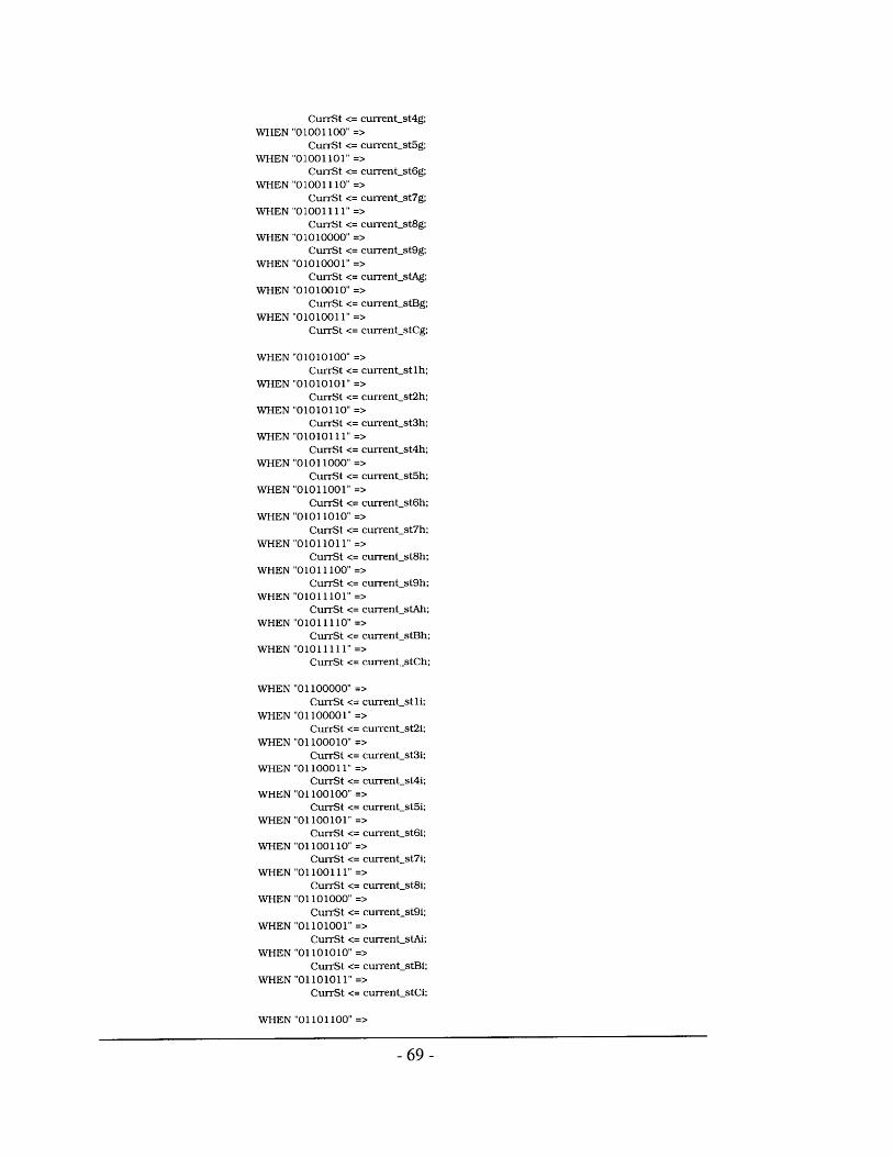
CurrSt <= currentst4g;WHEN "01001100" =>
CurrSt <= current-st5g;WHEN "01001101" =>
CurrSt <= current-st6g;WHEN "01001110" =>
CurrSt <= currentst7g;WHEN "01001111" =>
CurrSt <= current-st8g;WHEN "01010000" =>
CurrSt <= currentst9g;WHEN "01010001" =>
CurrSt <= current-stAg:WHEN "01010010" =>
CurrSt <= current-stBg;WHEN "01010011" =>
CurrSt <= current-stCg;
WHEN "01010100" =>CurrSt <= currentst1h;
WHEN "01010101" =>CurrSt <= current-st2h;
WHEN "01010110" =>CurrSt <= currentst3h;
WHEN "01010111" =>CurrSt <= current-st4h;
WHEN "0 1011000" =>CurrSt <= current-st5h;
WHEN "01011001" =>CurrSt <= current-st6h;
WHEN "01011010" =>CurrSt <= current-st7h;
WHEN "01011011" =>CurrSt <= current-st8h;
WHEN "01011100" =>CurrSt <= current-st9h;
WHEN "01011101" =>CurrSt <= current-stAh;
WHEN "01011110" =>CurrSt <= current-stBh;
WHEN "01011111" =>CurrSt <= current_stCh;
WHEN "01100000" =>CurrSt <= current-stli;
WHEN "01100001" =>CurrSt <= current-st2i;
WHEN "01100010" =>CurrSt <= current-st3i;
WHEN "01100011" =>CurrSt <= current-st4i;
WHEN "01100100" =>CurrSt <= current-st5i;
WHEN "01100101" =>CurrSt <= current-st6i;
WHEN "01100110" =>CurrSt <= currentst7i;
WHEN "01100111" =>CurrSt <= currentst8i;
WHEN "01101000" =>CurrSt <= currentst9i;
WHEN "01101001" =>CurrSt <= current-stAi;
WHEN "01101010" =>CurrSt <= current-stBi;
WHEN "01101011" =>CurrSt <= current-stCi;
WHEN "01101100" =>
- 69 -
CurrSt <= current stlj;WHEN "01101101" =>
CurrSt <= current-st2j;WHEN "01101110" =>
CurrSt <= current-st3j;WHEN "1101111" =>
CurrSt <= current-st4j;WHEN "01110000" =>
CurrSt <= current-st5j;WHEN "01110001" =>
CurrSt <= current-st6j;WHEN "01110010" =>
CurrSt <= current st7j;WHEN "01110011" =>
CurrSt <= current-st8j;WHEN "01110100" =>
CurrSt <= current-st9j;WHEN "01110101" =>
CurrSt <= current-stAj;WHEN "01110110" =>
CurrSt <= current stBj;WHEN "01110111" =>
CurrSt <= current-stCj;
WHEN "01111000" =>CurrSt <= current-stlk;
WHEN "01111001" =>CurrSt <= currentst2k;
WHEN "01111010" =>CurrSt <= current-st3k;
WHEN "01111011" =>CurrSt <= current-st4k;
WHEN "01111100" =>CurrSt <= current-st5k;
WHEN "01111101" =>CurrSt <= current-st6k;
WHEN "01111110" =>CurrSt <= current-st7k;
WHEN "01111111" =>CurrSt <= currentst8k;
WHEN "10000000" =>CurrSt <= current st9k;
WHEN "10000001" =>CurrSt <= currentstAk;
WHEN "10000010" =>CurrSt <= current-stBk;
WHEN " 100000 11" =>CurrSt <= current stCk;
WHEN "10000100" =>CurrSt <= current stil;
WHEN "10000101" =>CurrSt <= current-st2l;
WHEN "10000110" =>CurrSt <= current_st3l;
WHEN "10000111" =>CurrSt <= currentst4l;
WHEN "10001000" =>CurrSt <= currentst5l;
WHEN "10001001" =>
CurrSt <= currentst6l;WHEN "10001010" =>
CurrSt <= currentst7l;WHEN "10001011" =>
CurrSt <= current-st8l:WHEN "10001100" =>
CurrSt <= currentst9l;WHEN "10001101" =>
CurrSt <= current stAl;
- 70 -

WHEN "10001110" =>CurrSt <= current-stBl;
WHEN "10001111" =>CurrSt <= current-stCl;
WHEN OTHERS =>NULL;
END CASE;ELSE
delayOdelay4delaypasswriteaaddressa <=
END IF;END IF;
ELSIF (pass = '1') thenIF (delayO = '0') then
delayO <=ELSIF (delay4 = '0') then
delay4 <=
ELSEIF (delay = '0') then
IF (delayl = '0') thendelaylPrevStCurrRod
ELSIF (delay2 = '0') thendelay2temp
ELSIF (delay3 = '0') thendelay3position <=
ELSEdelaydelayldelay2delay3
END IF;ELSE
delayO <= '0';
delay <= '0';
writea <= '1';pass <= '0';IF (RodNumber(7) = '1' AND
RodNumber(4) = '1') thenRodNumber <= "00000000";
ELSE
<= '0';<= '';
<= '';<= '1';<= '';
RodNumber;
-- toggle modes
- next time around will read new data-- setup address for next time around
'1';
'1':
dataouta(8 DOWNTO 7); -- get next rod's input state
dataouta(6 DOWNTO 0); -- and put position and PrevSt
'1';
CONVINTEGER(CurrRod); -- type conversion
<= ' 1';CONVUNSIGNED(temp, 7); -- finally put it in position
-- write coming up 2 more cycles-- toggle modes
-- increment RodNumber until 144 <10010000> then reset
RodNumber <= RodNumber + 1: -- but don't put RodNumber in addressa until mode 0
END IF;CASE PrevSt is
WHEN "00" =>dataina(8 DOWNTO 7) <= CurrSt;IF (CurrSt= "10") then
IF (position = 0000000) thenposition <= position;
ELSE
-- set PrevSt equal to CurrSt
CurrRod <= CONVSTDLOGICVECTOR(position- 1,7);PrevRod <= CONVSTDLOGICVECTOR(position- 1,7);
END IF;ELSIF (CurrSt= "01") then
IF (position(6) = '1' ANDposition(5) = 1' ANDposition(4) = '1' ANDposition(3) = '1' ANDposition(2) = '1 ANDposition(1) = '1'then
- 71 -

position <= position;ELSE
CurrRod <= CONVSTDLOGICVECTOR(position+1,7);PrevRod <= CONVSTDLOGICVECTOR(position-1,7);
END IF;ELSE
position <= position;END IF;
WHEN "01" =>dataina(8 DOWNTO 7) <= CurrSt;
IF (CurrSt= "00") thenIF (position = 0000000) then
position <= position;ELSE
CurrRod <= CONV-STD-LOGICQYECTOR(position- 1, 7);PrevRod <= CONCSTDLOGICECTOR(position-1,7):
END IF;ELSIF (CurrSt= 11" then
IF (position(6) = '1' ANDposition(5) = '1' ANDposition(4) = '1' ANDposition(3) = '1' ANDposition(2) = '1' ANDposition(1) = '1') then
position <= position;ELSE
CurrRod <= CONVSTDLOGICVECTOR(position+ 1,7);PrevRod <= CONVSTDLOGICVECTOR(position-1,7);
END IF;ELSE
position <= position;END IF;
WHEN 10" =>dataina(8 DOWNTO 7) <= CurrSt;
IF (CurrSt= "11") thenIF (position = 0000000) then
position <= position;ELSE
CurrRod <= CONVSTDLOGICVECTOR(position- 1,7);PrevRod <= CONVSTDLOGICVECTOR(position-1,7);
END IF;ELSIF (CurrSt= "00") then
IF (position(6) = '1' ANDposition(5) = 1' ANDposition(4) = '1' ANDposition(3) = '1' ANDposition(2) = 1' ANDposition(1) = '1') then
position <= position;ELSE
CurrRod <= CONVSTDLOGICVECTOR(position+ 1,7);PrevRod <= CONVSTDLOGICVECTOR(position-1,7);
END IF;ELSE
position <= position;END IF;
WHEN "11" =>dataina(8 DOWNTO 7) <= CurrSt;
IF (CurrSt= "01") thenIF (position = 0000000) then
position <= position;ELSE
CurrRod <= CONVSTDLOGICVECTOR(position- 1,7);PrevRod <= CONVSTDLOGICVECTOR(position- 1,7);
END IF;ELSIF (CurrSt= "10") then
IF (position(6) = '1' AND
- 72 -

position(5) = '1' ANDposition(4) = '1' ANDposition(3) = '1' ANDposition(2) = '1' ANDposition(1) = '1') then
position <= position:ELSE
CurrRod <= CONVSTDLOGICVECTOR(position+1,7);PrevRod <= CONVSTDLOGICVECTOR(position-1,7);
END IF;ELSE
position <= position;END IF;
WHEN OTHERS =>dataina(8 DOWNTO 7) <= CurrSt;position <= position:
END CASE;END IF:END IF;END IF;
END IF;END PROCESS get-data;
-- INSTANTIATE COMPONENTS
-- Instantiate 9 x 256 Dual Port RAM-- Model generated by Genmem Version 2.8, on Mon Jul 03 17:38:04 2000
ram: csdpramGENERIC MAP (LPMWIDTH => 9,PORT MAP (
clock =>
clockx2 =>wea =>
web =>dataa =>datab =>addressa =>
addressb =>
qa =>
qb =>
busy =>
LPMWIDTHAD => 8, LPMNUMWORDS => 256)
slwclk,clk,writea,writeb,dataina,datainb,addressa,addressb,dataouta,dataoutb,membusy
incoutcount: PROCESS (update)BEGIN
writeb <= O';
datainb <= "000000000";IF (update'event AND update = '1') then
IF (OutCount(7) = '1' ANDOutCount(4) = '1' ANDOutCount(2) = '1') thenOutCount <= "00000000";
ELSEOutCount <= OutCount + 1;
END IF;END IF;
END PROCESS inc-outcount;
-- increment OutCount until 148 <10010100> then reset
- 73 -

put-data: PROCESS (slwclk)BEGIN
WAIT UNTIL slwclk'EVENT AND slwelk = 1';IF (update = '1') then
IF (OutCount(7) = '1' AND OutCount(4) = '1' AND(OutCount(2) = '1' OR OutCount(1) = '1' OR OutCount(O) = '1')) then -- 145 through 148
OutPos <= "11111111"; -- send header OxFF
ELSEIF (wait 1 = '0') then -- set memory address to current output
rodaddressb <= CONV-STDLOGICVECTOR(OutCount,8);wait1 <='1';,
ELSIF (wait2 = '0') thenwait2 <= '1';
ELSIF (wait3 ='') thenwait3 <= '1';
ELSIF (wait4 = 'O') thenwait4 <= '1';
ELSIF (wait5 = 'O') thenwait5 <= '1';
ELSIF (wait6 = '0') thenwait6 <= '1';
ELSIF (wait7 = '0') thenwait7 <= '1';
ELSIF (wait8 = 'O') thenwait8 <= '1';
ELSIF (wait9 = 'O') thenIF (membusy = '0') then -- check if dataa is doing a write
OutPos <= '0' & dataoutb(6 DOWNTO 0);wait9 <= '1'; -- set the output for the current rod
END IF;END IF;
END IF;ELSIF (update = '0') then
waiti <= '0';wait2 <= '0';wait3 <= '0';
wait4 <= '0';wait5 <= '0';wait6 <= '0';wait7 <= '0';waitS <= '0';wait9 <= 'O';
END IF;END PROCESS put-data;
out val <= OutPos;
clockgen: PROCESS (clk)BEGIN
WAIT UNTIL clk'EVENT AND clk = '1';slwclk <= NOT (slwclk);
END PROCESS clock-gen;
END rtl;
- 74 -

Bibliography
[1] Ashenden, P.: The Designer's Guide to VHDL. Morgan Kaufmann, San Francisco, CA.1995.
[2] Bischoff, J., Gold, R., and Horton, J.: "A microcomputer-based network for liveperformance." Computer Music Journal 2(3), pp. 24-29. 1978.
[3] Cage, John - A Page for John Cage, http://www.emf.net/maal/cage.
[4] ColorKinetics, http://www.fingerworks.com/.
[5] Davenport, G., Agamanolis, S., Barry, B., Bradley, B.: Dream Machine: CINEMAT.Presented in Exploding Cinema 27th International Film Festival, Rotterdam, January 28 -February 8, 1998, and at Espacio '98, Mexico City, Mexico, March 30 - April 4, 1998.
[6] Davenport, G., Agamanolis, S., Bradley, B., Sparacino, F. Encounters in DreamWorld: AWork in Progress. Consciousness Reframed, 1 t International CAiiA ResearchConference, University of Wales College, Newport, Wales, July 1997.
[7] Dodge, Charles & Jerse, Thomas A. Computer Music: Synthesis, Composition, andPerformance. New York: Schirmer Books, 1985.
[8] FingerWorks - MultiTouch Technology, http://www.fingerworks.com/.
[9] Gan, Seum-Lim: Squeezables: Tactile and Expressive Interfaces for Children of AllAges. Cambridge, MIT Media Lab Masters Thesis, 1998.
[10] Gerzso, A.: Reflections on Repons. Contemporary Music Review, Vol. 1, Part 1, pp. 23-24, Amsterdam, 1984.
[11] Goldstein, E. Bruce. Sensation and Perception. California: Brooks/Cole PublishingCompany, 1996.
[12] Intille, S., Baird, F., Schutte, A., et. al. (1996). "The Kidsroom: A Perceptually-BasedInteractive and Immersive Story Environment." IC Technical Report.
[13] Java - Sun Microsystem's Java Developer Site, http://www.javasoft.com/.
[14] Lewis, G., Roads, C. ed.: Composers and the Computer. William Kaufmann, Inc., Los
Altos, 1985.
[15] Lillington, K.: "Sounds Interactive". The Irish Times, July 28, 2000,http://www.ireland.com/newspaper/features/2000/0728/feal.htm.
[16] Machover, T: Brain Opera Update, January 1996. Internal Document, MIT Media
Laboratory, 1996.
-75-

[17] Machover, Tod. Hyperinstruments: A Progress Report. Cambridge: MIT - Media Lab,1992.
[18] Marrin, Teresa & Picard, Rosalind: The Conductor's Jacket: a Testbed for Research onGestural and Affective Expression. Cambridge: MIT Media Lab
[19] Mathews, M., Moore, F: "GROOVE-A Program to Compose, Store, and Edit Functionsof Time", Communications of the ACM, Vol. 13, No. 12, 1970.
[20] Mathews, M., Pierce, J.: Current Directions in Computer Music Research. The MITPress, Cambridge, MA. 1989.
[21] Max/MSP - Publisher of Max and MSP, Cycling'74. http://www.cycling74.com/.
[22] MIDI Manufacturer's Association, http://www.midi.org/.
[23] Oliver, William David: The Singing Tree: A Novel Interactive Musical Experience.Cambridge, MIT Media Lab Masters Thesis, 1997.
[24] Open Sound Control at U.C. Berkeley's Center for New Music and AudioTechnologies,http://cnmat.cnmat.berkeley.edu/OSC/.
[25] Paradiso, J., Gershenfeld, N: "Musical Applications of Electric Field Sensing."Submitted to Computer Music Journal, 1995.
[26] Paradiso, Joseph A: The Brain Opera Technology: New Instruments and GesturalSensors for Musical Interaction and Performance. In Journal of New Music Research,No. 2, pp. 130-149. Netherlands: Swets & Zeitlinger, 1999.
[27] Paradiso, J.A. & Sparacino, F. Optical Tracking for Music and Dance Performance.Fourth Conference on Optical 3-D Measurement Techniques, Zurich Switzerland,September 29-October 2, 1997.
[28] Paradiso, J., Hsiao, K., & Hu, E.: "Interactive Music for Instrumented Dancing Shoes."Proc. of the 1999 International Computer Music Conference, October 1999, pp. 453-456.
[29] QuickTime - Apple Computer's QuickTime Developer Site,http://developer.apple.com/quicktime/.
[30] Roads, Curtis. The Computer Music Tutorial. Cambridge: The MIT Press, 1996.
[31] Roads, C.: "Granular Synthesis of Sound." In C. Roads and J. Strawn, eds. Foundationsof Computer Music, pp. 145-159. The MIT Press, Cambridge, MA. 1985.
[32] Rowe, R.: Interactive Music Systems, Machine Listening and Composing. The MITPress, Cambridge, MA 1993.
- 76 -

[33] Sparacino, F., Hall, K., Wren, C., Davenport, G., Pentland, A. Improvisational TheaterSpace. The Sixth Biennal Symposium for Arts and Technology, Connecticut College,New London, CT, February 27 -March 2, 1997.
[34] Stockhausen, Karlheinz: Electronische Studien I und II. London: Universal Edition,1968.
[35] Stockhausen, K.: Kontakte, (On Compact Disk), Universal Edition, Wien, 1959-1960.
[36] Subotnick, M.: Interview with Morton Subotnick. Contemporary Music Review, Vol. 13,Part 2, pp. 3-11, Amsterdam, 1996.
[37] SuperCollider Home Page, http://www.audiosynth.con.
[38] Tactex Control, Inc.: Multi-touch, pressure sensitive input devices. Tactex web site:http://www.tactex.com/
[39] Termen, L.S., & Galeyev, B.: "Faustus of the Twentieth Century", in Leonardo (24), No.5, 1991. p. 573-579.
[40] Vasulka, Steina & Woody: Curriculum Vitae,http://www.c3.hu/scca/butterfly/Vasulkas/cv.html.
[41] Weinberg, Gil: Expressive Digital Musical Instruments for Children. Cambridge, MITMedia Lab Master's Thesis, 1999.
- 77 -