the elomatic magazine 2 · 2015 · the elomatic magazine 2 · 2015 ... ispe (international society...
TRANSCRIPT

The Elomatic Magazine 2 · 2015
Consulting • Engineering • Design • R & D • Innovation • Technical Solutions
Juhani KääriänenCyber-security enables more intelligent automation solutions page 18
Anita VuorenmaaCorrosion in district cooling systemspage 26
Anna-Mari HämäläinenThe new welding symbol standard – something new, something oldpage 30
“Careful and systematic adherence to guidelines is key in delivering GMP compliant facilities and processes.” – Heikki Niskanen

The Elomatic Magazine · 2 | 3
At the time of writing this editorial I have been the CEO of Elomatic for close on 20 years and employed within
the Elomatic Group for 33 years. In October we announced that I will vacate my position as CEO and make way for Patrik Rautaheimo, who will take over the reins of the company on 1.1.2016. At the same time Elomatic founder, Ari Elo, will step down as Chairman of the Board of Directors and I will take up that post.
The fact that we have managed to make this smooth transition tells something about our corporate culture, val-ues and the continuity of our operations. I, for one, am very excited about our future.
When I started out as CEO of Elomatic there was already a culture of investing in development, both in engineering methodologies and in people. We have further strength-ened this over the years and have been able to turn this into growth and customer satisfaction. Our goal is to develop our employees’ know-how so they can be leaders in their respec-tive technical fields. To us it is clear that human capital is our most precious asset. It is the core of our value proposition to our customers.
Investing in our employees by encouraging them and giving them the freedom to enhance their know-how and develop new methods and technologies is also a key factor in creating concepts and products that can eventually be marketed as standalone or turnkey deliveries; a key element of our strategy to drive international growth.
A good example of this is the top know-how we have de-veloped in the field of sterile manufacturing. In this edition of the Top Engineer we highlight this know-how in two of the articles. This top know-how has brought us to the point where we can with confidence offer turnkey sterile manu-facturing plants worldwide. This is now a fast growing business area for us. This kind of know-how is, however, not developed overnight; it takes years of hard work by a dedicated team and a corporate culture that facilitates learning. It requires people with positive curiosity.
In Patrik Rautaheimo we have a future CEO that has bought into our culture of development during the few years he has worked with us and will no doubt take us to new heights in the years ahead. His career to date includes ambitious and successful design de-velopment projects in international environments and engineering directorships in Germany and Finland. We at Elomatic, and you as our highly valued client and partner, are in safe hands.
I look forward to the challenge of being part of and contributing to Elomatic in my new capacity as Chairman of the Board of Directors. Ari Elo will also continue as a member of the board and as such his wise inputs are not lost to us.
As autumn sets in the winds of positive change are blow-ing through Elomatic. We will adapt and change in our evolving environment, but stay true to the principles that have brought us this far. By investing in and valuing our peo-ple we invest in our own success, and that of our customers.
The winds of change
Olli MannerEditor-in-ChiefPresident, CEO

Contents
2/2015
Publisher ElomaticItäinen Rantakatu 7220810 Turku, FinlandTel. +358 2 412 [email protected]
Editor-in-ChiefOlli [email protected]
EditorMartin [email protected]
Art DirectorOlli [email protected]
Anita Vuorenmaa
Corrosion in district cooling systems
26
Juhani Kääriäinen
Cyber-security enables more intelligent automation solutions
18
Anna-Mari Hämäläinen
The new welding symbol standard– something new, something old
30
If you would like to receive a copy of the Top Engineer, or would like to be added to our Top Engineer mailing list please send your request to [email protected].
Elomatic believes that all information provided in this publication is correct at the time of printing. Elo-matic is not responsible for any inadvertent errors.
Elomatic holds the copyright to all materials con-tained in this publication, unless specified otherwise. Written permission from Elomatic is required for the reproduction of articles in whole or in part.
Cover: Heikki Niskanen, Senior Consulting Engineer at Elomatic. Cover photo © Olli Tuomola / Elomatic. Background cover photo © depositphotos.com/photosoupy.
Elomatic has donated this year’s Christmas gift funds to develop the Tampere University Hospital’s pediatric clinic in Tampere, Finland.
Elomatic India and Heikki NiskanenEngineering for sterile product manufacturing facilities – A GMP overview 4
Markku Mäkinen A practical approach to GMP cleanrooms and cleanroom HVAC 10
Arto Sampo, Pasi AhonenRaising competitiveness and innovation potentials – EU funded RePCI project leading the way 16
Timo Rauma Structural Analysis – A brief history: 1980s to 2010s 23
Martin BrinkInvesting in technology and personnel development bears fruit– Case Cadmatic 34
The Elomatic Magazine · 4 | 5The Elomatic Magazine · 4 | 5

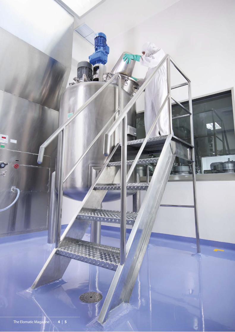
Processing of sterile medicinal products is one of the most critical operations in pharmaceutical manufacturing due to the highly technique-driven processes and the potential detrimental impact on patients. Since sterile manufacturing is subject to inspections by different regulatory authorities, such as the US FDA, WHO and EMA, it is imperative to be thoroughly familiar with Good Manufacturing Practice (GMP) regulations and their application.
It is noteworthy that most GMP regu-lations describe what needs to be ac-
complished, rather than how it should be accomplished. A disciplined ap-proach is, therefore, required to meet the requirements.
This article provides an overview of the regulatory guidelines and the fun-damental GMP requirements with re-gards sterile manufacturing of medic-
inal products, with a particular focus on engineering aspects. It should be remembered, however, that engineer-ing is only the basis and that quality as-surance is vitally important. Manufac-turing must strictly follow the carefully established and validated methods of preparation and prescribed procedures. An overview of the relevant regulato-ry authorities and their publications is provided in the info box (see overleaf ).
Sterile manufacturing processes re-quire close coordination and interac-tion between personnel, equipment systems, cleanroom and support facil-ities, and sterilized components.
Recommendations by the various authorities regarding premises, room classification, area classifications for various processes, equipment, person-nel, processing, and sterilization are outlined in the following paragraphs (according to WHO’s guidelines and with comparison to guidelines of oth-er regions).
Risk management concepts (ICH Q9 guidance) and modern pharmaceutical
quality systems (ICH Q10) should be in-troduced in the design and during pro-duction of pharmaceutical preparations. These concepts are already noted in the Sterile Product Manufacturing Facilities guide (Volume 3, Sept. 2011, ref. 9) by ISPE (International Society for Pharma-ceutical Engineering) and are under preparation and discussion in the EU (Concept paper on the revision of An-nex 1, February 2015) as well as in the Pharmaceutical Inspection Convention’s co-operation scheme (PIC/S).
It needs to be kept in mind that the manufacture of sterile preparations should be carried out in clean areas, and operations are divided into two categories:
■ products which are terminally steri-lized; and
■ products which are produced asep-tically at some or all stages.
Tables 1a and 1b on page 8 illustrate typical production operations in differ-ent clean room areas in these two ster-ile manufacturing categories.
Engineering for sterile product
manufacturing facilities – A GMP overview
Text: Elomatic India and Heikki Niskanen
Phot
o © de
posit
phot
os.co
m/p
hoto
soup
y
The Elomatic Magazine · 6 | 7
Manufacture of sterile preparations
Each manufacturing operation in the manufacture of sterile products requires an appropriate level of environmental cleanliness of the operational state to minimize the risk of particulate or mi-crobial contamination of the product or materials being handled (ref. 5).
For processing it is recommended that separate facilities be used for prod-ucts that contain live microorganisms and those that don’t, except when the product contains properly inactivated organisms, or the deactivation/con-tainment can be demonstrated/vali-dated. All possible efforts should be made to reduce the bio-burden even before sterilization. These guidelines also guide the media fill procedure, media selection, batch size, frequency, and interpretation of simulation results for the validation of aseptic processing.
Minimizing and validating the time interval between various processing stages is recommended, for example, between equipment cleaning and ster-ilization, equipment sterilization and formulation, as well as between formu-lation and product sterilization. These guidelines also highlight specific pre-cautions and advantages of isolator and blow-fill-seal technologies. The EU GMP and WHO focus on routine moni-toring and frequent leak testing of iso-lators and glove/sleeve systems.
One of the most important labo-ratory controls is the environmental monitoring program. The monitoring program should cover all production shifts and include air, floor, walls, and equipment surfaces, in particular sur-faces that come in contact with the product, container, and closure.
Sterilization
Various sterilization methods such as heat sterilization, filtration sterilization, radiation sterilization, and ethylene ox-ide sterilization are accepted by the authorities; but where possible, heat sterilization should be the method of choice. Each load type and load pattern
has to be validated. Biological indicators should be considered as an additional method for monitoring sterilization and indicators such as autoclave tapes and radiation sensitive colour discs should be used to clearly distinguish the steri-lization statuses of objects.
Whenever possible products intend-ed to be sterile should be terminally sterilized with heat in the final contain-er (ref. 5). Filtration sterilization is ac-ceptable when sterilization in the final container is not possible due to the in-stability of a formulation or incompat-ibility of a pack type. Since sterile grade filters (≤0.22 µm or less) cannot remove all viruses and mycoplasma; considera-tion should be given to some degree of heat treatment to complement the filtration process.
It is recommended to use anoth-er sterile grade filter immediately prior to the filling point. The maximum us-age duration of a single filter should be demonstrated by validation. Filter integrity testing requirements are also suggested in the guidelines and filters should be non-shedding and not affect the product composition via absorp-tion/leaching.
The FDA requires sterility testing methods to be accurate and repro-ducible while the EU GMP and WHO point out that sterility tests applied to the finished product should only be re-garded as the last in a series of control measures whereby sterility is assured. The test should be validated for the product(s) concerned.
Personnel
It is suggested that personnel be mini-mized in clean rooms. All personnel including housekeeping and main-tenance staff should be trained in manufacturing (aseptic techniques), cleanroom behaviour, personnel hy-giene, gowning and basic microbiol-ogy (ref. 1). To avoid cross contami-nation dedicated persons should be employed unless rigorous and clearly defined decontamination procedures have been followed.
Wrist-watches, cosmetics, and jew-ellery shall be strictly avoided (refs 3, 6). These guidelines also suggest ap-propriate gowning requirements with respect to clean room grades, gown material quality, frequency of chang-ing clothes and gloves, sanitization of gloves, and requirements for dedicated and separate laundry.
Premises
With regards premises all the regu-latory authorities agree that the de-sign of a given area needs to satisfy microbiological and particle criteria defined for the operational activities along with the fulfilment of require-ments for equipment, components, and products. The recommendation is for smooth, impervious, and sanitizable surfaces with sealed false ceilings. They advise against drains in grade A or B ar-eas. For other grades they indicate that equipment drains should be equipped with air gaps and floor drains with wa-ter seal/traps.
These guidelines also provide the necessary input for room pressure dif-ferentials, air flow rates, air flow pat-terns, interlocks for change rooms, and the number of change rooms (sepa-rate changing rooms for entering and leaving may be desirable, ref. 3). They also indicate that swing doors should open into high-pressure areas and be provided with self-closers and that un-necessary access should be restricted to critical manufacturing areas.
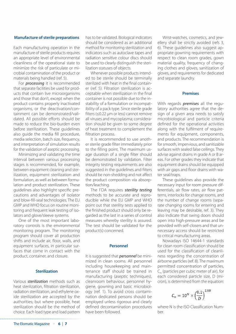
Nowadays ISO 14644-1 standards for clean room classification should be used for the classification of cleanli-ness regarding the concentration of airborne particles (ref. 8). The maximum permitted concentration of particles, Cn (particles per cubic meter of air), for each considered particle size, D (mi-cron), is determined from the equation:
where N is the ISO Classification Num-ber.

Info box Regulatory authorities and relevant publications
US Food and Drug Administration (FDA)The FDA publishes regulations and guidance documents. Its Code of Federal Regulations (CFR) is a codification of the general and permanent rules published by the Federal Government, which is divided into 50 titles that represent broad areas subject to federal regulation.
Title 21 of the CFR is reserved for FDA rules and updated annually on April 1. It contains general regulations for pharmaceuticals including manufacturing, processing, packing, or holding of a drug, and rules for design and construction features of buildings and facilities, ventila-tion, air filtration, as well as air heating and cooling and di-rections regarding the use of defined areas and controlled conditions to prevent contamination (Part 210, and 211). It also covers general instructions for equipment selection with respect to equipment design, size and location, con-struction, cleaning and maintenance, as well as guidelines for automatic, mechanical and electronic equipment and filters.
The CFR delineates GMP for complete manufacturing activities from raw material issuance to final product dispatch from the facility. There are also special regulatory parts for Quality Systems (Part 820) and Electronic Records (Part 11).
The FDA’s guidance documents represent the agency’s current thinking on a particular subject and as non-binding guides they act as the reference for inspectors and manufacturers. The most relevant guidelines for the manu-facturing of sterile products are contained in Guidance for Industry: Sterile Drug Products Produced by Aseptic Process-ing — Current Good Manufacturing Practice (Sep 2004), and Non-Penicillin Beta-Lactam Drugs: A CGMP Framework for Preventing Cross-Contamination (April 2013).
European Union GMP (EU GMP)The rules governing medicinal products in the EU are published in various EudraLex volumes containing EU leg-islation and guidelines that support the basic legislation. Volume 4 of the European publication contains guidance for the interpretation of the principles and guidelines of good manufacturing practices for human and veterinary medicinal products specified in EU directives.
Directive 2003/94/EC (8 Oct 2003) lays down the principles and guidelines of good manufacturing practice in respect of medicinal products for human use and investigational medicinal products for human use while Directive 91/412/EEC (23 Jul 1991) covers the principles and guidelines of
good manufacturing practices for veterinary medicinal products. Annex 1, Manufacture of Sterile Medicinal Prod-ucts, (Nov. 2008) of Volume 4 of European Good Manu-facturing Practice Guidelines specifically explores sterile medicinal product manufacturing.
World Health Organization (WHO)One of the WHO’s constitutional functions is to provide objective and reliable information and advice in the field of human health, a responsibility that it fulfils in part through its extensive programme of publications. WHO ex-pert committees have made numerous recommendations contained in annexes to several WHO Technical Report Series (TRS). Today TRS 986 (2014) Annex 2 profiles the WHO’s thinking with regards the main GMP principles for pharmaceutical products.
The WHO Good Manufacturing Practices for Sterile Phar-maceutical Products (Annex 6, WHO Technical Report Series 961, 2011) describes its regulatory requirements for sterile manufacturing.
International Organization for Standardization (ISO)The ISO has published a number of standards relevant to pharmaceutical manufacturing, of which ISO 14644 for clean rooms and associated controlled environments is the most adhered to by industry.
ISO 14644 Cleanrooms and associated controlled environments
Part 1: Classification of air cleanliness
Part 2: Specifications for testing and monitoring to prove continued compliance with ISO 14644-1
Part 3: Test methods
Part 4: Design, construction and start-up
Part 5: Operations
Part 7: Separative devices (clean air hoods, glove boxes, isolators and mini-environments)
Part 8: Classification of air cleanliness by chemical con-centration (ACC)
Part 9: Classification of surface cleanliness by Particle Concentration
Part 10: Classification of Surface Cleanliness by Chemical Concentration

The Elomatic Magazine · 8 | 9
Table 2 presents selected airborne particulate cleanliness classes and the corresponding particle concentrations for particles equal to and larger than the considered sizes shown.
The US FDA defined area classifica-tion is provided in Table 3. USFDA con-siders only In-operation condition and for 0.5 µm particle size only.
The EU GMP & WHO defined area classification is provided in Table 4. EU GMP & WHO considers limits ‘at rest’ as well as ‘in operation’. Also, these regula-tions consider 5 µm particle size along with 0.5 µm particle size. These regu-lations don’t define ‘in operation’ lim-its for Grade-D; the company should establish in operation limits based on a risk analysis and on historical data where applicable.
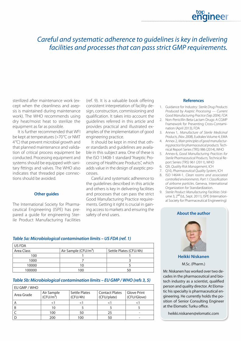
During operation the manufacturer should monitor airborne particles and microbiological contamination. In this context FDA accepts the use of settle plates only as optional for continuous air sample measurements (Table 5a); while for WHO / EU GMP, the use of settle plates and glove prints are com-pulsory (Table 5b).
A new version of EU GMP Annex 15 (Qualification and Validation) has been published describing the principles of qualification and validation for facili-ties, equipment, utilities and processes. Annex 15 takes into account current changes to other sections of EudraLex, Volume 4, Part I, the relationship to Part II, Annex 11, ICH Q8, Q9, Q10 and Q11, QWP guidance on process validation, and changes in manufacturing tech-nology. This version has been opera-tional from 1 October 2015.
Equipment
For equipment the guidelines suggest that a conveyor should not pass from a Grade A/B room to a lower grade room unless the conveyor is continu-ously self-sanitized. They also suggest that the technical parts of equipment should be placed outside clean rooms and that equipment and the clean room be cleaned, disinfected and/or
Table 1a: Operations in various grades for terminally sterilized products – EU GMP (ref. 3)Terminally Sterilized ProductsGrade Operations
A ■ Filling of ‘unusually at risk’ products
C ■ Filling of Products ■ Solution preparation of ‘unusually at risk’ products
D ■ Solution preparation ■ Components preparation for subsequent filling
Table 1b: Operations in various grades for aseptic preparations – EU GMP (ref. 3)Aseptically Processed Products
Grade Operations
A ■ Aseptic Preparations ■ Product Filling
C ■ Preparation of solution to be filteredD ■ Component handling after washing
Table 2: Area Classification – ISO (ref. 8)ISO Classifica-tion Number, N
Maximum concentration limits (particles/m³ of air) for particles equal to and larger than the considered sizes shown below 0.1µm 0.2µm 0.3µm 0.5µm 1µm 5µm
ISO Class 1 10 2
ISO Class 2 100 24 10 4ISO Class 3 1000 237 102 35 8ISO Class 4 10000 2370 1020 352 83ISO Class 5 100000 23700 10200 3520 832 29ISO Class 6 1000000 237000 102000 35200 8320 293ISO Class 7 352000 83200 2930ISO Class 8 3520000 832000 29300ISO Class 9 35200000 8320000 293000
Table 3: Area Classification – US FDA (ref. 1)Clean Area Classification(0.5 µm particles/Cu.ft) ISO Designation ≥0.5 µm Particles /Cu. m
100 5 3,5201000 6 35,200
10000 7 352,000100000 8 3,520,000
Table 4: Area Classification – EU GMP / WHO (refs 1, 5)
Area Grade
Maximum permitted number of particles per cubic meter greater than or equal to the tabulated size RemarksAt rest In Operation0.5 µm 5 µm 0.5 µm 5 µm
A 3520 20 3520 20 For both (at rest & in operation) ISO 5 for 0.5 µm particles & ISO 4.8 for 5 µm particles
B 3520 29 352000 2900 ISO 5 ‘at rest’ & ISO 7 ‘in operation’C 352000 2900 3520000 29000 ISO 7 ‘at rest’ & ISO 8 ‘in operation’D 3520000 29000 - - ISO 8 ‘at rest’
sterilized after maintenance work (ex-cept when the cleanliness and asep-sis is maintained during maintenance work). The WHO recommends using dry heat/moist heat to sterilize the equipment as far as possible.
It is further recommended that WFI be kept at temperatures (>70 °C or NMT 4 °C) that prevent microbial growth and that planned maintenance and valida-tion of critical process equipment be conducted. Processing equipment and systems should be equipped with sani-tary fittings and valves. The WHO also indicates that threaded pipe connec-tions should be avoided.
Other guides
The International Society for Pharma-ceutical Engineering (ISPE) has pre-pared a guide for engineering Ster-ile Product Manufacturing Facilities
(ref. 9). It is a valuable book offering consistent interpretation of facility de-sign, construction, commissioning and qualification. It takes into account the guidelines referred in this article and provides practical and illustrated ex-amples of the implementation of good engineering practice.
It should be kept in mind that oth-er standards and guidelines are availa-ble in this subject area. One of these is the ISO 13408-1 standard “Aseptic Pro-cessing of Healthcare Products”, which adds value in the design of aseptic pro-cesses.
Careful and systematic adherence to the guidelines described in this article and others is key in delivering facilities and processes that can pass the strict Good Manufacturing Practice require-ments. Getting it right is crucial in gain-ing access to markets and ensuring the safety of end users.
References1. Guidance for Industry: Sterile Drug Products
Produced by Aseptic Processing — Current Good Manufacturing Practice (Sep 2004), FDA
2. Non-Penicillin Beta-Lactam Drugs: A CGMP Framework for Preventing Cross-Contami-nation (April 2013), FDA
3. Annex 1, Manufacture of Sterile Medicinal Products, (Nov. 2008), Eudralex Volume 4, EMA
4. Annex 2, Main principles of good manufactur-ing practice for pharmaceutical products. Tech-nical Report Series (TRS) 986 (2014), WHO
5. Annex 6, Good Manufacturing Practices for Sterile Pharmaceutical Products, Technical Re-port Series (TRS) 961 (2011), WHO
6. Q9, Quality Risk Management, ICH 7. Q10, Pharmaceutical Quality System, ICH 8. ISO 14644-1. Clean rooms and associated
controlled environments. Part 1: Classification of airborne particles. Geneva, International Organization for Standardization.
9. Sterile Product Manufacturing Facilities (Vol-ume 3, 2nd Ed., Sept. 2011), ISPE (Internation-al Society for Pharmaceutical Engineering)
About the author
Heikki Niskanen
M.Sc. (Pharm.)
Mr. Niskanen has worked over two de-cades in the pharmaceutical and bio-tech industry as a scientist, qualified person and quality director. At Eloma-tic his specialty is pharmaceutical en-gineering. He currently holds the po-sition of Senior Consulting Engineer at the Elomatic Turku office.
Careful and systematic adherence to guidelines is key in delivering facilities and processes that can pass strict GMP requirements.
Table 5a: Microbiological contamination limits – US FDA (ref. 1)US FDAArea Class Air Sample (CFU/m³) Settle Plates (CFU/4h)
100 1 11000 7 3
10000 10 5100000 100 50
Table 5b: Microbiological contamination limits – EU GMP / WHO (refs 3, 5)
EU GMP / WHO
Area Grade Air Sample (CFU/m³)
Settle Plates (CFU/4h)
Contact Plates (CFU/plate)
Glove Print (CFU/Glove)
A <1 <1 <1 <1B 10 5 5 5C 100 50 25 -D 200 100 50 -

The Elomatic Magazine · 10 | 11
A practical approach to GMP cleanrooms and cleanroom HVAC
The Elomatic Magazine · 10 | 11

A practical approach to GMP cleanrooms and cleanroom HVAC
Identifying the most practical approach to achieve Good Manufacturing Practice (GMP) cleanrooms and cleanroom HVAC in the pharmaceutical industry does not require an “out of the box” or innovative approach. It rests, rather, on the comprehension of and adherence to a set of basic rules that have been penned by several GMP regulatory authorities. Rules are nevertheless open to subjective interpretation and herein lie some potential pitfalls. The International Society for Pharmaceutical Engineering (ISPE) provides invaluable and much needed guidance in this regard.
Phot
o © de
posit
phot
os.co
m/D
mitr
y Kali
novs
ky
Text: Markku Mäkinen

The Elomatic Magazine · 12 | 13
The most commonly used GMP reg-ulations that govern the design of
pharmaceutical cleanrooms and clean-room HVAC systems include the EU GMP, PIC/S GMP, FDA cGMP, and WHO GMP.
What is clean and how particle-based cleanliness is specified depends on what standards are applied. The world community of cleanroom de-signers mostly follows the ISO 14644 standard family for this purpose. Clean-room designers and builders should concentrate on the first five parts of the standard family depicted in Table 1.
ISPE has provided a set of tools that facilitates a clearer understanding of the application of different GMP reg-ulations, standards and guidelines in everyday work. Without these base-lines it would be difficult to find suit-able solutions to GMP matters. ISPE creates a bridge between pharma-ceutical engineers and regulative au-thorities by writing baselines, good
engineering practices and monthly articles in its ”Pharmaceutical Engi-neering” magazine.
The ISPE publication series includes ISPE Baselines, ISPE GAMP Guidance documents, ISPE Guides and Good Practice Guides, ISPE Investigational Products Resources, and ISPE Regu-latory. This excellent source of refer-ence information combined with en-gineers’ practical experience allow most clients’ GMP related questions to be solved. Local laws and codes naturally have to be applied in every aspect in order for project goals to be fulfilled. Once a project has started the ISPE general V-model should be fol-lowed (see Figure 1)
According to the V-model all GMP projects should start with a properly executed risk assessment based ap-proach which leads to the appropriate Validation Master Plan (VMP) and final-ly to project-specific User Requirement Specification (URS). All GMP cleanroom
projects should follow this generally accepted route:
Conceptual Design ↓Basic Design (or Functional Design) ↓Detail Design ↓Design Review and/orDesign Qualification ↓Implementation (Construction) ↓Installation Qualification ↓Operational Qualification ↓Performance Qualification
Every phase has to be approved and completed with documented confir-mation before proceeding to the next phase. It all starts from the user re-quirements and ends with the very
EN-ISO 14644-1 Classification of Air Cleanliness
EN-ISO 14644-2 Specifications for Testing and Monitoring to Prove Continued Compli-ance with ISO 14644-1
EN-ISO 14644-3 Test Methods
EN-ISO 14644-4 Design, construction and start-up
EN-ISO 14644-5 Operations
► Table 1. The first five parts of the standard family are of importance for cleanroom designers.
▼ Figure 1. The ISPE general V-model
Project ManagementDefine Scope
Procure BudgetDevelop Timelines
Validation Plan(VP)
Risk Assessment
Performance PlanQualification (PQ)
and CQ
Validation PlanSummary Report
Design Construction Qualification Maintenance
User Requirements
(URS)
Functional Requirements
(FRS)
OperationalQualification (OQ)
and CQ
Design Specifications
(DDS)
Installation Qualification (IQ)
and CQ
PreventiveMaintenance
Commissioningand Qualification
CommissioningEngineering Runs
FAT/SATBuild Calibration
Change Control
Re-Qualification

same user requirements. All require-ments in the URS need to be fulfilled or approved with documented devia-tions.
User requirements
When the URS for cleanrooms or cleanroom HVAC is written in the conceptual design phase by the plant operator (often with engineers’ assis-tance) and approved, one can pro-ceed to the basic design phase (or the functional design). the URS is ar-guably the most important document in the whole GMP project as it defines all the users’ (GMP) critical demands for the process, clean utilities, clean-rooms, cleanroom HVAC and black utility. URS in the GMP context means a documented definition of the key re-quirements stated by the user.
The URS must state what GMP reg-ulations should be followed and what
cleanliness grades are required. EU GMP and FDA cGMP requirements are the two mostly referred to but also WHO and Japanese regulations can be used if applicable.
Cleanrooms can be constructed in various ways, but the first thing that has to be solved is the layout, which is governed by basic rules. Figure 2 dis-plays the main principle of a shell-like barrier system where the cleanliness grades are always separated by person-nel airlocks, material airlocks or pass-through cabinets.
Layout design should only be start-ed once a clear understanding of the user requirements has been gained. The basic rules for airlocks and pressure cascading regimes should, however, be checked first. Here again ISPE has some useful models. See Figure 3 (overleaf ) for a layout with cleanliness grades and pressure cascading.
There are some differences in clean-liness grades between the US and EU
which need to be kept in mind when designing cleanrooms for different reg-ulatory environments. US GMP covers three cleanliness grades: supporting clean areas in two grades and critical areas. EU GMP includes four cleanli-ness grades: A, B, C and D. This differ-ence affects design especially when sterile drugs are produced in aseptic processing.
The crucial role of HVAC
Once layout work is completed the HVAC designer can begin working. HVAC is only a small part of a clean-room – but a very important part. With-out a well-functioning HVAC system the desired conditions for production might not be achievable. HVAC sys-tems for cleanrooms are relatively ex-pensive and take up much space, but are essential for the critical product pa-rameters.
► Figure 2. A shell-like barrier system
People Change
Transition ZoneBrings people, materials, etc. from external areas
to the manufacturing areas in a “controlled” manner
External AreasStreet, offices, restaurant
Supporting Clean AreaProvides a protective envelope to minimize
the challange to the Critical Areas
Sterilize
Remove outers
Raw materials
Remove outers
Container/closures
Product out
WasteSamples
Critical Areae.g. Point of FillChange Compounding

The Elomatic Magazine · 14 | 15
HVAC systems also represent large operating costs. It firstly needs to be decided what type of ventilation princi-ple would best satisfy the URS require-ments: recirculated air or outside air? Recirculated air means a ventilation system where e.g. 80% of air flow is in constant circulation and only 20% is replaced with fresh air from outside. A 100% fresh air system uses non-recircu-lated air from the outside.
It is preferable to use recirculated air in a cleanroom ventilation system if it is not prohibited for any reason as the use of recirculated air reduc-es energy consumption and emission levels.
Direct and indirect impact systems
It is of critical importance to deter-mine whether the HVAC system has a direct or indirect impact on the prod-
uct. According to the ISPE guidelines a direct impact system “is expected to have a direct impact on product qual-ity. These systems are designed and commissioned in line with Good En-gineering Practice and in addition, are subject to qualification practices that incorporates the enhanced review, control, and testing against specifica-tions or other requirements necessary for cGMP compliance.” ISPE indicates that an indirect impact system “is not expected to have a direct impact on product quality, but typically will sup-port a direct Impact system. These sys-tems are designed and commissioned following Good Engineering Practice only. Indirect impact systems can af-fect the performance or operation of a direct impact system.”
Once the impact type of the system has been determined, the appropriate commissioning and validation activities can be applied.
Critical parameters
The so-called critical parameters for products manufactured in a clean-room environment need to be speci-fied in the URS. According to the ISPE guidelines there are several factors that need to be considered and the onus is on the designer to gather all the rele-vant information (see the info box for details):
Validation of cleanrooms and cleanroom HVAC
The first validation activity in cleanroom and cleanroom HVAC projects is the DQ whereas the last is the approval of all the
CNC
Packing hall (not directly
pressure controlled)
Changing room / airlock
Changing room/ airlock
(measured at rest)
Component preparation
Pass thru airlock
Final rinse
Grade C30 Pa
Grade C30 Pa
Aseptic processing room 145 Pa
Grade BGrade B
“Critical” AreasGrade AAirflow direction
Washing / sterilizing tunnel
Autoclave
Autoclave loading room
Cooling area (“Sterile corridor”)15 Pa
“Building” areas (general)
Aseptic processing room 245 Pa
Grade B
▼ Figure 3. A layout with cleanliness grades and pressure cascading.

required design documents. When eve-rything is complete a design qualifica-tion (DQ) report is drawn up and signed. It is a generally applied approach that construction work cannot be started be-fore design qualification is done.
The next step is construction, which is followed by commissioning (C), in-stallation qualification (IQ), operation-al qualification (OQ) and finally perfor-mance qualification (PQ). Each has to be approved before the next step can start and approval of all steps has to be documented.
ISPE defines commissioning as a “well planned, documented, and man-aged engineering approach to the start-up and turnover of facilities, sys-tems, and equipment to the end-user that results in a safe and functional en-vironment that meets established de-sign requirements and stakeholder ex-pectations”.
Validation on the other hand “en-sures that the facility and system qual-ification (DQ, IQ, OQ and PQ) require-ments are communicated and met.”
Conclusion
The procedures outlined in this arti-cle provide a practical guide to GMP cleanrooms and cleanroom HVAC in the Pharmaceutical industry. The ba-sic rules change frequently and it is the responsibility of designers and engineers to follow this and keep up to date with related developments. This is the best way to ensure that the quality of our skills and services con-sistently meet the demand of our cli-ents worldwide.
About the author
Markku Mäkinen
M. Sc. (HVAC Engineering)
Mr Mäkinen has worked within the Finnish and Swedish building construction industry, pharmaceuti-cal industry and food industry for the last 34 years. His experience and know-how covers feasibility studies, conceptual design, basic design, de-tail design and site supervision. In re-cent years he has focused on pharma-ceutical cleanroom HVAC projects. Mr Mäkinen joined Elomatic in 1982. Af-ter gaining experience further afield in 2006 he rejoined Elomatic in 2009 where he currently works as a Senior Design Manager.
Info box
Critical Attribute A physical, chemical, biological or microbio-logical property or characteristic that should be within an appropriate limit, range, or distribution to ensure the desired product quality (ICH Q8(R2))
Critical Process Parameter A process parameter whose variability has an impact on a critical quality attribute and therefore should be monitored or controlled to ensure the process produces the desired quality (ICH Q8(R2))
Critical Parameter (in HVAC) A room variable (such as temperature, humidity, air changes, room pressure, par-ticulates, viable organisms, etc.) that, by law or by determination from pharmaceutical product development data, affects product strength, identity, safety, purity, or quality (SISPQ)
Acceptance Criterion The predetermined result of a special test. In HVAC, the upper and lower limits of the room environment (critical parameters). If these limits are exceeded, the exposed pharmaceutical product may be considered adulterated.
HVAC is a small but crucial part of any cleanroom implementation.

The Elomatic Magazine · 16 | 17
In many industrial fields Europe is finding it increasingly difficult to compete with low-cost countries that are successfully challenging the value proposition of European technologies. European welfare is nevertheless still dependent on its industries and mechanical engineering know-how in general. In order to compete now and in the future the European Union, industrial companies and educational institutions have to think out of the box and create new synergies that foster the creation of competitive advantages. A recently completed EU funded project named Reshaped Partnerships for Competitiveness and Innovation Potentials in Mechanical Engineering (RePCI), which was coordinated by the JAMK University of Applied Sciences in Finland, is a good example of such thinking.
Since the inception of the EU it has provided funding for universities
and companies via several different pro-grammes. The Erasmus program, which was established in 1987 and is currently continuing under the Erasmus+ um-brella, is the EU’s flagship education and training programme in the field of higher education. It not only supports mobility, but also provides co-funding to higher education institutions (HEI) through transnational cooperation projects. Within Erasmus the Life Long Learning Programme provides funding for higher education purposes in Eu-rope. There is also large scale national funding available for universities. These resources have, however, not been op-timally utilized to support the compet-itiveness of industrial companies and one of the purposes of RePCI project was to find and use those resources more effectively and in new way.
Participants from Finland, Hungary, Romania and Germany
The JAMK University of Applied Scienc-es in Jyväksylä, Finland led the EU fund-ed RePCI project from 2013 to 2015.
The RePCI project was tasked with creating a new strategic cooperation model between universities and indus-try that does not rely on individual in-terests and/or particular cases. The pro-ject participants included JAMK and Elomatic from Finland, Miskolc Univer-sity, Konecranes and Fux from Hunga-ry, Cluc-Napoca University and Prototip from Romania, as well as the Esslingen University of Applied Science in Ger-many. Festo from Germany participat-ed in the project without EU funding.
The effectiveness of the coopera-tion was based on commonly select-ed competence areas between the companies and universities. The crux of the idea is that universities are able develop their educational offering bet-ter when they are thoroughly familiar with the competence requirements of industry players.
During the RePCI project coopera-tion agreements were signed between the universities and partner companies where the strategic areas of coopera-tion and the commitment to a system-atic approach were confirmed. SWOT analyses of the partner companies and universities were conducted and served as the basis for competence de-
Raising competitiveness and innovation potentials– EU funded RePCI project leading the way

velopment, while action plans based on the common areas of development were also agreed.
The RePCI project allowed all par-ticipants to become more familiar with how other European HEIs cooperate with industry players. This informa-tion is extremely useful when plan-ning new projects and cooperation activities. The possibility to benchmark teaching at HEIs in different countries and student competencies interna-tionally is important for international companies and HEIs.
Another significant achievement of the project was the acquisition of the information and connections required for international student exchange. During the RePCI project student groups worked together on partner company tasks.
Product R&D projects in university laboratories
A further useful aspect of RePCI was that it provided the partner companies with information regarding the use of labora-tory capacities at foreign universities for product research and development pro-jects. The key point was understanding that HEIs are not only a source for new engineers, but have the potential to be partners in a continuous dialog about the future competencies required in the competitive global market of mechani-cal engineering products.
A competence coaching concept was also tested in Hungary and Roma-
nia during RePCI. The concept is based on the use of pedagogical approach-es used in HEI institutions in the de-velopment of knowledge in partner companies. Staff from the HEIs worked as coaches in training projects inside partner companies. As a result the first competence matrix of job descriptions was created, which outlined what skills are required by industry players going forward. The industrial partners were also involved in ensuring that these identified competences were included as intended in the teaching programs.
A key result of the project was that it deepened the cooperation between the universities and companies in-
volved and elevated the cooperation from an operational level to a more strategic level. Both the HEIs and their partner companies will reap the bene-fits of the deeper strategic cooperation over the long-term.
In some countries legislation needs to be adjusted to make the coopera-tion between educational institutions and companies easier. Development work is also required to identify the op-timal interface and how to retain flex-ibility in scheduling. It is clear, however, that precisely the kind of novel coop-eration seen during the RePCI project is what is needed on a much larger scale to bolster European competitiveness.
About the authors
Arto Sampo
B.Sc. (Machine Design), M.Sc. (Automation)
Arto Sampo has extensive experience in production line and production de-vice design. His experience covers de-sign, implementation and develop-ment projects since 1981. He has also taught special courses at the Jyväsky-lä University of Applied Sciences for more than 10 years. Arto has worked at Elomatic since 1990. His current po-sition is Business Area Manager, Pro-duction Development Projects.
Pasi Ahonen
M.Sc. (Paper Technology)
Pasi Ahonen is a Senior Lecturer, Pa-per Machine Technology at the Jy-vaskyla University of Applied Scienc-es. He has among others also worked at Metso Paper/Valmet, Mreal and RGE Group. His areas of expertise in-clude paper machine technologies, paper line investments and related value chain as well as process and mill engineering.
When universities are thoroughly familiar with the competence requirements of industry players
they can develop a better educational offering.
◄ A RePCI project meeting in Jyväskylä, Finland. On the far left, Arto Sampo, and on the far right, Pasi Ahonen.

The Elomatic Magazine · 18 | 19
Cyber-security enables more intelligent
The Elomatic Magazine · 18 | 19
automation solutions

Cyber-security is becoming increasingly prominent when it comes to automation. It is noteworthy that technical solutions can only remove 33% of all security threats and that two out of three attacks originate from within our own organizations. Firewalls cannot prevent an attack if malware is installed directly to the target on-site. How can and should cyber-security be handled and what does the future hold?
Cyber-security enables more intelligent automation solutions
Text: Juhani Kääriäinen

The Elomatic Magazine · 20 | 21
The cyber-security mind-set com-bines information security, conti-
nuity management and societal crisis preparation. As a concept, it covers the so-called digital world, which is con-nected to physical world practices and society as a whole where individual ac-tions and human error are an addition-al challenge.
Cyber-security can be divided into three different levels: strategic, opera-tive and technical. At the strategic lev-el, the company creates a cyber-secu-rity strategy that defines the actions that have a significant effect on per-formance. Actions that are greatly cy-ber-dependent can then be identified. Resources can thereafter be allocated to secure these critical actions and en-sure that the residual risk is acceptable. It will then, for example, be possible to insure the residual.
The operative level directs the strat-egy towards real actions, and the tech-nical level implements the technical actions according to the strategy. It is, then, important that cyber-security is managed and influenced by corpo-rate management as a strategy. Man-agement needs to work closely with the ICT department and ICT solutions must be based on management-de-fined strategic goals.
Taking cyber-security into account in automation
In automation, cyber-security is cre-ated through the chosen solutions. Equipment must be reliable, and from known operators. Cyber-security con-cerns all “intelligence” connected to the network or channel.
The creation of a new automation network, or the expansion of an exist-ing one, must proceed in phases so that cyber-security is observed. Work must always begin with a risk assess-ment to determine the cyber-securi-ty risks of the automation system. Af-ter this, the company’s cyber-security strategy, if one exists, comes into play, along with how that strategy is taken into account in the design or expan-sion of the automation system.
For technical reasons, the network must be segmented correctly and sen-sibly (DMZ, isolated, etc.) while deter-mining access to company and other (external) networks. Equipment secu-rity surveys are an important part of cyber-security. Inspections of equip-ment with or without network connec-tions include their identifier, type and explanation in addition to passwords.
Info box
The International Organization for Standardization defines the “preservation of confidentiality, integrity and availability of infor-mation in the Cyberspace” in its standard, ISO/IEC 27032:2012.
Security standards for industrial automation systems:
IEC 62443-1-1: Terminology, con-cepts and models
IEC 62443-2-1: Establishing an in-dustrial automation and control system security program
IEC 62443-3-1: Security technolo-gies for industrial automation and control systems
Cyber-security – visions for the future
Technological progress and digitisation enable the market of applied cyber-security. The growth of computing power and its distribution, storage capacity and network traffic create possibilities for growth in the IT business and cyber-security will, eventually, become a thing of utmost importance for everyone.
It is clear that everything that can be digitised will be!
Openness, networking and internationality will continue expanding and companies will communicate openly and learn from each other. A company’s credibility won’t be questioned if it is targeted in a cyber-attack. It is more credible to admit to having been attacked than not.
■ Digital and physical security will merge and be referred to simply as security.
■ Digital information will become an asset and a commodity.
■ The reliability of digital data will become more important.
■ The importance of personal information security will increase: identity theft, privacy, etc.
■ We will have to learn to live with “hackers” who will gain access to our systems no matter what.
Illustr
ation
© ti
gerli
ly713

The passwords should be strong and the equipment password list must be kept in a secure location. In addition, the possibility of upgrading old devices with new ones must be investigated.
In many cases, industrial networks are completely disconnected from the Internet, which means they can only be accessed on-site. Even in this case, the risk of a virus being installed on an on-site computer remains, regardless whether done on purpose or by acci-dent. This is where “hardening” a com-puter is helpful.
Not all automation networks are, however, entirely disconnected from the Internet. Inspecting firewall con-figurations is integral to finding out whether unnecessary traffic has been blocked and default settings changed appropriately. For example, in a worst-case scenario, routers/firewalls may have been left in “nearly default” set-tings, and the connections to removed devices unrevoked.
In many cases, it is necessary to ac-cess an automation system from the outside. Remote access is provided with industrial-grade VPN equipment. The devices contain a firewall and a VPN server. A static IP address or dy-namic DNS is required and the use of an Industrial VPN Appliance rather than a cloud-based remote connectivity ser-vice is recommended.
The design must also take physi-cal information security into account, which entails limitations to access / disposal of sensitive papers / locking doors, etc. If necessary, a training ses-sion for proper use of the system can be held as a part of the delivery.
Usability is an integral part of cyber-security and also connected to physi-cal information security. If a device be-comes overly difficult to use due to security concerns it can in itself consti-tute a cyber-security risk. If a device’s
user experience is poor, it is possible that it may be misused or used in a way that is less secure. An example of this would be writing down complicat-ed, frequently-changed passwords on a post-it note next to devices.
Manufacturing execution systems (MES)
Manufacturing execution systems add intelligence to manufacturing execu-tion and optimisation. Intelligent field devices that are connected to an in-dustrial-grade system with remote ac-cess require a secure framework to ensure their functionality. There is a large amount of information that can be gathered from the manufacturing process and that creates the possibil-ity for, among other things, industrial espionage.
When discussing mobile devices, the term “fleet management” is often used. Workstations maintain a connec-tion to a server that gathers a host of information and creates reports on, for example, working hours, machine loca-tion and its working condition.
Storing information (Big Data)
As MES and Fleet Management solu-tions become more common, it will be increasingly important to gather data. Over 99% of data is stored in digital for-mat and the amount of stored data is constantly growing. As the Internet of Things (IoT) expands, intelligence is dis-tributed ever further and linked via the Internet. Smart devices communicate with host machines, which increases the amount of gathered information. Raw data can be used to collect infor-mation and draw conclusions on cost efficiency, among other things. Some
examples include actions related to preventive maintenance, such as meas-urements related to bearing heat or ab-normal vibrations in a device.
As the amount of data grows, more attention will certainly have to be paid to data integrity and confidentiality. In the future data itself and refining “raw data” into a useful format will become a commodity. As this happens, it is para-mount that the information is correct and unmodified.
About the author
Juhani Kääriäinen
M.Sc. Eng. (Process Automation)
Juhani Kääriäinen holds a graduate degree in process automation from the Oulu University. After graduating in 2000 he has worked in research and training as well as in consulting and engineering. He also has several years’ experience in sales and market-ing. Currently Juhani works at the Elo-matic Jyväskylä office as the Design Manager of the Electrical and Auto-mation Engineering Team.
In the future data itself and refining raw data into useful formats will become a commodity.

The Elomatic Magazine · 22 | 23The Elomatic Magazine · 22 | 23

All consulting work comes with its own challenges and responsibilities – fiscal for the company and moral for the individual designer. In the field of structural analysis, this is abundantly clear at all times. Incorrect analysis can lead to personal injuries and significant economic ramifications. Structural analysis as a field of engineering has gone through many changes in the past four decades. In this article I take a closer look at these changes as I experienced them.
I signed my name on a work contract in September 1984, as a freshly grad-
uated Master of Science from the Uni-versity of Oulu. This meant moving from East Lapland to Finland Proper in the south, which was like moving to another country; I almost couldn’t un-derstand the dialect. I faced structural analysis with the same bewilderment.
Elomatic had employed structural analysts before, or at least so I under-stood, but the company didn’t have any material on any performed struc-
tural analyses. At first, the work was much like laying a foundation – fortu-nately no rocket science was required in the beginning.
Changes in data transfer have turned more than just my field upside down. In the beginning, all we had were tel-ephones and the post, along with cus-tomer meetings, which we definitely had more of than we do now. Structur-al analysis, especially in the early days, was a challenging field for gaining cus-tomers’ and colleagues’ trust.
Calculation methods and tools have seen many changes
The fact that I was among the first to be allowed to use a calculator instead of having to use a slide rule in my ma-triculation exam tells its own story.
The early calculations were often based on standards and used ana-lytical solutions we found in litera-ture. Some well-informed customers provided very helpful dimensioning guides. I also spent some time looking for help in my study materials, but it soon became apparent that the theo-
retical slant was of little use for practi-cal purposes.
Those analytical solutions, while be-ing theoretically accurate, could only be used for structures with a simple and clear geometry. There are tables for beams supported in different ways that show the distribution deflections and internal forces that the point load or distributed loads can exert. Similar calculations also exist for plates. Calcu-lation for more complicated structures was not, however, achievable with usu-al mathematics, so instead we had to settle for near-solutions gained with numerical methods. The most efficient of those methods we’ve found is the Finite Element Method (FEM), which is what we now use almost exclusively. The method is also often called Finite Element Analysis (FEA).
The finite element method in-volves creating a simplified calcula-tion model on a computer for the structure under analysis using solu-tion-appropriate structural parts that are called elements. The elements are joined together with node points. The solution of node displacements (translations and rotations) is, in fact,
Structural Analysis – A brief history: 1980s to 2010s
Text: Timo Rauma
Phot
o © 20
15 O
lli Tu
omola
/ Elo
mat
ic

The Elomatic Magazine · 24 | 25
a solution for an equation set with n unknowns and n equations. The ele-ment stresses can be calculated from the displacements of the nodes re-lated to them. The figure n is called the calculation model’s number of de-grees of freedom, which indicates the magnitude of the solution.
This simplified description of a fi-nite element method can be used as a bridge to our current level of pro-gress. Financially sensible computers and software in the 1980s were able to calculate a solution with a few hun-dred degrees of freedom, and today we even use calculation models with millions of degrees of freedom. I re-member a calculation we did on a train sleeper carriage’s partition wall sup-porting structure – it took two weeks on a workstation machine (rough shell element model and non-linear large deflection calculation). Today, that would have taken no more than a few seconds.
The finite element method came into use in the 1950s in the USA. The method improved along with comput-ers and a large amount of commercial software was already available in the 1970s. The software ran on mainframes and was hard to use, as the inputs had to be made manually in numerical for-mat. Even the results had to be read in numerical form in massive tables. The analyst had to have an excellent understanding of what the calculation was, and confirmation of the results was necessary as well.
Improved software user-friendliness
in 80s and 90s
In the 1980s and 90s, the software start-ed becoming more user-friendly. It was called graphical interactivity: when cre-ating a calculation model, the analyst would be given immediate graphical feedback, and the results were view-able in graphical form as well. As the development of personal computers kicked into full force in the 1990s, the finite element method started becom-ing a more useful and efficient tool.
We have used FEM calculations in structural analysis since the early 1980s. At the time we performed our beam calculations on HP computers, using Stafra software, which was made with HP Basic. For shell and solid calculations we used British software called Pafec (on a UNIX mainframe). Both of these 1980s software programs were slow and labour-intensive to use. The scope of the calculation models was extreme-ly limited. We had to simplify the struc-tural models and use symmetry and asymmetry constraints whenever we could. Since the 1990s and the person-al computer “revolution”, we’ve had ac-cess to a wealth of financially sensible structural analysis software suites. Dur-ing the DOS era, we used Beamex for beam structure calculations and ANSYS for shell and solid element model cal-culations. In Windows, we used Finnsap at first, and in the last few years our an-alysts have been using both ANSYS and
ABAQUS thanks to their wide feature-set.
As personal computers have im-proved, they have become far more cost-effective solutions. The calculation software suites have become more us-er-friendly. The geometry of a struc-ture can be transferred directly from 3D design software to the structural analysis suite. Using different non-lin-ear analyses (large displacement, plas-ticity, stability, etc.) provides us with more possibilities to use the finite ele-ment method.
Role and challenges of structural analysts
Generally speaking, the role and chal-lenges of a structural analyst are de-pendent on the nature of their place of employment. In extreme situations, companies that focus on a specific product or group of products can tai-lor the calculation methods to meet the needs of that specific product. The calculation involves the development, improvement and optimisation of a product the company has extensive experience in.
Engineering companies have a larg-er portfolio when it comes to both en-gineering and structural analysis – the analytics bring variety and challenges to our work.

In the beginning, when we had one or two structural analysts, the cal-culations mostly concerned our own engineering projects. Many assign-ments in the 1980s and 90s began with brainstorming, preliminary design and structural reviews. The analyst would take part in the project, if not as the project lead, in a capacity that helped carry the project through. Analysts would in other cases fill the time be-tween calculation projects by taking part in engineering work. This helped them understand how structures work and to become familiar with manufac-turing requirements.
Today, the structures under analysis are often already engineered or even manufactured, when for some reason, a structural analysis is required (by an authority or an inspection body, or when the structure does not meet re-quirements for some reason, etc.).
The “hand-in-hand” development of information technology and structural analysis software has, over the years, ended up with us using different piec-es of software. The competition be-tween analysis suite providers often leads to an accelerating versioning cy-cle as they add features and correct mistakes. Keeping up with their pace while providing competitive structural analysis services poses its own chal-lenge. Today, students become famil-iar with the use of FEM program pack-ages while studying for their degrees. The youth are growing up using in-formation technology and are better
equipped to adapt to the current world of calculation.
As calculation capacity increas-es and software develops, it has be-come possible to create very specific calculation models for very significant structures. Even in real situations, a structure’s points of discontinuity are subject to peak tensions (or “hot spots”) that are limited to the material’s yield strength. The hot spots shown by cal-culation models may also be caused by an inappropriate element grid. It can be said that sometimes, the more you know, the more you suffer when inter-preting the results.
The amount of norms and stand-ards used in calculation is constantly growing, partly thanks to common EU standards and the internationalisation of work.
Balance between technology and practical know-how
Despite all the technological advance-ments and changes we have witnessed in the field of structural analysis over the years there are some things that haven’t changed. It is, for example, still vitally important that analysts are con-vinced of the results of their work in one way or another. The modern an-alyst relies to a great extent on soft-ware tools and the immense process-ing power of modern computers to conduct analyses instantly. We could not even dream of such calculations
25 years ago. One nevertheless still has to be able to look at results and use your experience and common sense to question and verify results.
About the author
Timo Rauma
M.Sc (Mechanical Engineering)
After working as an assistant for one year at Oulu University, Timo joined Elomatic in September1984. His expe-rience covers strength calculations of steel structures (e.g. cranes, harbour equipment etc.).
A standout project in his career was the strengthening of the bow struc-tures and visors for all Viking Lines’ car ferries. The work was based on rule modifications caused by the Estonia catastrophe and consisted of preli-minary design, strength calculations, applying for maritime class approval and leading the drawing design work.
A calculation that took two weeks in the 1980s can now be done in a few seconds.

The Elomatic Magazine · 26 | 27
District cooling is becoming an increasingly popular way of cooling properties and special facilities. In such cooling systems corrosion represents a serious risk to the integrity of the steel pipes used. The conditions in district cooling systems differ from those in district heating systems and are in many ways unique. In order to mitigate the threat posed by corrosion many factors have to be considered and controlled.
Corrosion refers to the deteriora-tion of materials, usually metals,
via chemical interactions with their environment (see the info box for an overview of the corrosion process). Corrosion can take many forms: Gen-eral or uniform corrosion proceeds uni-formly over the entire surface area as the oxidation and reduction occur on the same surface while the anode and cathode change their positions con-tinuously. In water, though, corrosion tends to occur more often in its lo-cal forms. Pitting corrosion often origi-nates from a scratch or a crack in a protective film and results in holes in
the metal surface. A scratch or a pit functions as a local anode while the surface around it serves as a cathode. In district cooling systems local corro-sion appears often as crevice corrosion where a crevice, joint or a hidden pit under a deposit can create a micro-environment that enhances the cor-rosion attack.
Galvanic corrosion can take place where different metals are present in electrical contact with each other – the less noble metal will become an anode and corrode. There are many compo-nents made of different materials in a district cooling system, which means
Corrosion in district cooling
systemsText: Anita Vuorenmaa

Info boxBasics of corrosion
When a metal corrodes it is oxidized and emits electrons (1). These electrons are consumed in reduction reactions at the cathode. Usually reduction oc-curs with oxygen or with water that contains oxygen (2) or with hydrogen ions (3).
Fe → Fe²+ + 2e- (1)
O₂ + 2H₂O + 4e- → 4OH- (2)
2H+ + 2e- → H₂ (3)
However, a corrosion cell will form and corrosion can occur only if all the fol-lowing conditions are met:
1. There is both an anode (a surface to be oxidized) and a cathode (a surface where reduction takes place).
2. There is an electric potential difference between the anode and cathode.3. There is a metallic path between the anode and cathode that allows the
transfer of electrons.4. The anode and cathode are submerged in the same conductive solution
(electrolyte).
that galvanic corrosion is also a poten-tial threat in cooling networks.
Moreover, pipelines in a cooling sys-tem can also be damaged by erosion corrosion. This is due to chemical cor-rosion as well as mechanical wearing caused by high velocity fluids in the sys-tem. Loose particles, such as solid cor-rosion products, that are drifting in the flow can accelerate the wearing effect.
If a pipeline is exposed to residual or applied stresses in a corrosive environ-ment stress corrosion cracking (SCC) may be induced. High pH levels and nitrite ion concentrations increase the risk of SCC for carbon steel pipes.
Phot
o © Tu
rku E
nerg
ia, El
ina Ki
vil. P
hoto
for il
lustra
tion p
urpo
ses.

The Elomatic Magazine · 28 | 29
The role of microbes in corrosion
Corrosion that is induced or affected by microbes, i.e. microbiologically influ-enced corrosion (MIC), has often been given too little attention. There is much evidence indicating that microbes can play a highly significant role in corro-sion attacks. Many microbes are toler-ant of harsh conditions and can live in unfriendly environments such as those found in district cooling systems. How-ever, relating the observed corrosion attack to microbes can be difficult; find-ing microbes at the damaged site does not necessarily prove that microbes are to blame.
There are several ways microbes affect corrosion and not all of these are fully understood. Microbes essen-tially influence corrosion by changing the electrochemical conditions at the metal-solution interface. Micro-organ-isms, of which the most abundant are bacteria, live on a pipe surface in the form of a biofilm. Microbes can pro-duce organic or inorganic acids and extracellular corrosive metabolites or concentrate chloride, oxygen, hydro-gen or metal ions under the biofilm. The biofilm can act as a barrier that blocks the free movement of mole-cules and ions, thus affecting the con-centrations of chemical substances. Consequently, the conditions under a biofilm can differ significantly from the conditions elsewhere in the sys-
tem, potentially creating a corrosive microenvironment.
The role of microbes is made even more complicated by the fact that they can also inhibit corrosion. They can, for example, consume oxygen that is needed for cathodic reaction, produce inhibitory metabolites, or stabilize the protective film on the metal surface. Some microbes can also produce an-tibiotics that inhibit the growth of cor-rosion-inducing microbes.
A district cooling system is mostly an oxygen depleted environment. The most important microbes that cause MIC under anaerobic conditions are sulfate reducing bacteria (SRB). They can promote corrosion in different ways and cause severe corrosive dam-age. It has to be remembered though, that microbial communities consist of many different microbes and there are numerous complicated biochemical re-actions and interactions involved.
Factors affecting the corrosion rate
The maintenance of proper water chemistry in piping systems is crucial in minimizing the corrosion risk. There are, however, many elements in water chemistry that interact, thereby mak-ing the system highly complex. Opti-mal control over the corrosion rate in a cooling network may still require some fine-tuning of the conditions and dif-ferent elements in the system.
The two most critical factors in re-spect of the corrosion rate are the ox-ygen content and pH level. Oxygen typically accelerates corrosion mark-edly, but the relation is not that sim-ple: a small amount of oxygen pro-motes the formation of an oxide layer that can protect the metal surface from corrosion. This kind of protec-tive or passivating film on the surface of carbon steel usually consists mostly of magnetite Fe₃O₄ which – when con-ditions are favourable – forms a dense layer that adheres tightly to the steel surface.
However, excess oxygen or destabi-lization or destruction of the magnetite layer can increase the corrosion rate. In district heating systems hydrazine is used as a scavenger for residual oxy-gen, but its reaction rate is very slow in cooling network temperatures, which means that it does not really work in such conditions. There is still a lack of a simple and practical oxygen scavenger for district cooling systems.
Typically fluid acidity speeds up cor-rosion. A high hydrogen ion concen-tration accelerates the cathodic reac-tion, but a low pH also destabilizes the magnetite layer which makes the metal surface more susceptible to corrosion attacks. This is why water is kept alka-line in cooling systems. A very high pH can, however, also damage or destabi-lize the oxide layer. Thus the optimal pH in respect of corrosion control is usually 9–10.
◄ A scanning electron microscopy (SEM) image of microbial growth on the in-side surface of a carbon steel pipe.
Phot
o © VT
T

Water treatment is also used to gain low hardness and low conductivity. Chloride and sulfate ions are examples of strongly corrosive elements, but some salts that affect conductivity can also be corrosion inhibitors. A tempera-ture rise is known to accelerate the cor-rosion rate as it usually does for chemi-cal reaction rates.
However, the final effect is a sum of several factors. As the temperature rises the diffusion rate of oxygen in-creases, oxygen solubility decreases, pH falls, conductivity is enhanced and the properties of corrosion products can change.
The temperature also affects the growth rate of microbes. In district cooling systems temperatures are rel-atively cool and the differences are not that large: the temperature is usually about 8 °C in supply pipes and about 16 °C in return pipes.
Other factors in the system that af-fect the corrosion rate are e.g. the flow rate, materials and compounds that act as nutrients for microbes, and different metals that can cause galvanic corro-sion. Loose particles such as magnetite deposits can induce corrosion through erosion and also by sedimentation – as particles deposit on the pipe surface they can form pockets that function as a suitable microenvironment for corro-sion to develop or microbes to grow. In addition, differences in altitudes in the network can affect the distribution of gases, including oxygen.
Can plastic pipes be a corrosion risk?
In the future, high-density polyethyl-ene (HDPE) plastic pipes may be used in district cooling systems. HDPE pipes have many advantages compared to steel pipes: They are light and flexible and therefore easy to install. They are also not vulnerable to corrosion nor do they erode easily. Moreover, the heat conductivity of HDPE is much lower than that of steel, which reduces the need for insulation.
The problem with HDPE pipes in water systems is that plastic allows some oxygen diffusion, which may lead to corrosion of steel parts. The lev-el of oxygen diffusion is dependent on the material density, the wall thickness, the size of the exposed area, tempera-ture, and whether the pipes are buried in soil or placed in tunnels or cellars.
Studies indicate, however, that there is only minor oxygen diffusion through HDPE pipes in district cooling systems. Oxygen leaks through pipe accessories during network operations in fact pose a much larger corrosion risk. Oxygen diffusion should not be a problem with HDPE pipes as long as there is sufficient steel in the network.
It is clear that corrosion control in district cooling systems requires careful water quality management, prevention of oxygen leaks, particle and sediment removal, and appropriate installation work to avoid contamination. Biocides
are not usually a long-term solution in MIC mitigation. A much more sustain-able way is to control the habitat con-ditions of microbes.
“The maintenance of proper water chemistry in piping systems is crucial in minimizing the corrosion risk.”
About the Author
Anita Vuorenmaa
M.Sc. (Biology and Environmental Sciences), B.Eng. (Energy Technology)
Anita Vuorenmaa has worked at Elo-matic since 2013. Her expertise covers a wide range of biological, chemical and environmental issues, as well as energy technology. In addition to bio-energy she has previously worked in ecotoxicological and microbiological research. At Elomatic her focus has, among others, been corrosion cont-rol and cleantech solutions such as ballast water treatment technologies.

The Elomatic Magazine · 30 | 31
Many years have passed since the SFS-EN 22553 welding symbolic representation was approved in 1994. It has now come to its end of its shelf life and a new symbol standard has been introduced. Approved in 2014, the new welding symbol standard has brought new symbols and methods of indicating welds in more detail.
The basics of welding symbols have not changed. A welding symbol
still consists of a reference line and an arrow line, both of which are required elements. The other elements of a
welding symbol are the tail, as well as elementary and supplementary sym-bols. One of the most noteworthy ad-ditions in the new standard is that it identifies welding symbols that are used in most Pacific Rim countries.
A compromise solution between the European system and Pacific Rim system could not be found in the new standard and as such it includes two different symbolic presentations. This means that there are two different sys-tems to designate the arrow side and the other side. The European system (system A in the standard) uses a dual reference line which includes a contin-uous line to indicate the arrow side and a dashed line to indicate the other side.
The Pacific Rim (AWS) system (system B in the standard) is based on a single ref-erence line where the arrow side is al-ways on the underside of the reference line, as shown in Figure 1.
When using welding symbols these two systems should not to be used alongside each other and there should be a clear indication as to which sys-tem is in use. All the new welding sym-bols are not available in the symbol libraries of all 3D-modeling software programs. Most of the new elemen-tary and supplementary symbols can be found using a different symbol li-brary, such as JIS, but some of the sym-bols unfortunately need to be hand-crafted.
The new welding symbol standard– something new, something old
Text: Anna-Mari Hämäläinen
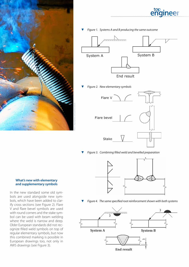
What’s new with elementary and supplementary symbols
In the new standard some old sym-bols are used alongside new sym-bols, which have been added to clar-ify cross sections (see Figure 2). Flare V and flare bevel symbols are used with round corners and the stake sym-bol can be used with beam welding where the weld is narrow and deep. Older European standards did not rec-ognize filled weld symbols on top of regular elementary symbols, but now this combined marking is possible in European drawings too, not only in AWS drawings (see Figure 3).
▼ Figure 4. The same specified root reinforcement shown with both systems
▼ Figure 3. Combining filled weld and bevelled preparation
▼ Figure 2. New elementary symbols
▼ Figure 1. Systems A and B producing the same outcome
Phot
o © de
posit
phot
os.co
m/L
aure
ntiu
Iorda
che

The Elomatic Magazine · 32 | 33
One of the new supplementary symbols is the specified root reinforce-ment for butt welds welded from one side (see Figure 4). The standard states that the “symbol shall only be used when complete joint penetration plus a specified minimum root reinforce-ment dimension is required”.
This minimum measure for root re-inforcement can contradict the maxi-mum root cap height in the welding quality standard (SFS-EN ISO 5817) if it is not taken into account. In the qual-ity standard there is a maximum meas-ure for the same root cap height. Dur-ing weld quality inspections these two measurements can be in conflict if the minimum root reinforcement measure is greater than the allowed cap height.
There is a new way to emphasize the welding operation order if neces-sary. A multiple reference line has been included in the new standard and can be used to indicate the order of subse-quent operations. Welding operations are piled up in a line so that the first operation is closest to the arrow.
Point-to-point or full length?
The length of the weld has also re-ceived a makeover. The usual “non-measured” length is still valid and it is used to indicate that the weld is con-tinuous for the whole length of the joint. If the length of the weld is short-er than the joint the start point of the weld should be marked clearly and the measurement marked on the welding symbol to the left of the elementary symbol. This is nothing new.
What is new, however, is that the weld is done from point to point. A continuous weld with the same weld type and dimensions, which does
▼ Figure 8. Weld all-around
▼ Figure 7. Alternative butt weld symbol
▼ Figure 6. Weld from point to point
▼ Figure 5. Welding operation order starting from the bottom up
(Figures 1–8 source: SFS-EN ISO 2553 Welding and allied processes)

not start and stop at the same point can be marked with this new point-to-point symbol. The weld can con-tinue around the corner and cover more than one joint. The start and end points have to be clearly indicated in the drawing.
Beneath the surface
As with weld lengths butt welds are full penetrating unless otherwise dimen-sioned or if other information, such as WPS, is referred to. The designer dimen-sions the required minimum penetra-tion after strength calculation without assuming that the penetration will ex-ceed the minimum measure. Manu-facturers can then produce joint weld-ing in the most practical way to attain the minimum demand for weld quality and sizing.
The new standard contains guide-lines for the marking of dimensions for joint preparations, but implementa-tion requires knowledge of the man-ufacturer and its WPS-documents. In cases where the preparations are di-mensioned it cannot be assumed that another manufacturer would have the same dimensions in their WPS-docu-ments, and therefore the same pen-etration with exactly the same prepa-ration.
The same outcome can be achieved with different preparations. Small differ-ences in dimensioning are not crucial when manufacturers have approved their WPS-documents with destruc-tive testing and the penetration is con-firmed.
There is a new useful welding sym-bol that can be used if the manufac-turers are not known when welding drawings are being prepared (see Fig-
ure 7). The symbol contains only the weld quality and the required pene-trating depth, which means that the manufacturer can decide what prepa-ration to use to gain the desired qual-ity and dimensions. This symbol is very new and it should not be assumed that everyone is familiar with it. It is recom-mended that designers ensure that the manufacturer knows the meaning of the symbol.
Small circle, big meaning
A supplementary symbol that has had many interpretations over the years is the all-around symbol. It is intended for use in cases where the weld starts and ends at the same point and during the weld the dimensions and joint type do not change (see Figure 8). This doesn’t include circumferences of circular sec-tions, holes or slots as they naturally start and end at the same point. In oth-er words, all-around symbols can be used with profiles that have corners that need to be welded all around.
Sometimes the all-around symbol is used incorrectly. One of the most com-mon situations is when the weld type is changed for a small part. The designer might not even notice this or just feel that it does not need a dedicated weld-ing symbol. An example of this is when a joint is marked with an all-around filled weld and some part of the joint is a bevelled weld. This may cause con-fusion regarding how bevelled welds with fillet dimensions should be pro-duced and how inspectors will deal with this.
This all-around symbol is not the symbol for “weld everywhere”. When planning welds every welded joint
should be checked individually, not only for weld markings, but also for the welding order and accessibility.
The new standard has brought many useful improvements and ad-ditions to weld indications. The new elementary symbols are an especial-ly welcome addition. As manufactur-ing continues becoming increasingly international the need for an interna-tional symbol standard has likewise grown. The new standard will ensure that there are no longer diverging in-terpretations and misunderstandings between designers and manufacturers.
About the author
Anna-Mari Hämäläinen
M.Sc. (Mechanical Engineering)
Anna-Mari Hämäläinen has been wor-king as a Special Designer at Eloma-tic since 2012. She is specialized in welding and has an IWS qualificati-on (International Welding Specialist). She has consulted on welding issu-es and provided welding training to designers. She has also conducted mechanical design on a wide range of customer projects.
The new standard has brought many useful improvements and additions to weld indications.

The Elomatic Magazine · 34 | 35
Investing in developing operations and personnel most often has long-term positive business effects. A good example of this is a project that was started in the early 1980s at Elomatic to take advantage of 3D technology to improve the design, visualization, distribution and total cost efficiency of engineering projects. The spin-off from this development, Cadmatic, is today an independent company and 3D design software used in marine and plant design projects all over the world.
All development projects naturally do not end in similar productized
and commercial success stories. Case Cadmatic is, however, a reminder that when a knowledgeable and dedicated development team set their minds to improving their way of working, the re-sults can be far-reaching and add value even beyond initial expectations.
Early days of plastic modelling
For the young, so-called digital native generation, it may seem unfathoma-ble that engineering and design offices used to build large-scale plastic mod-els of process plants and vessels. In the 1970s and early 1980s this was how-ever state-of-the-art and skilled work, which was highly appreciated by cus-tomers. Plastic ship model technolo-
gy was, in fact, instrumental in gaining Elomatic’s first ship design contracts.
The advent of laser scanning tech-nology at the end of the 1970s opened the door to visualising such plastic models on computers and led to ideas of designing plants digitally.
In 1983 a project was launched to develop a 3D plant design program and by 1985 the first pilot project us-ing the new 3D technology was com-pleted. The new technology proved to be much more efficient than tradi-tional ways of working and compet-ing systems available on the market at the time. As such it was decided in the early 1990s not only to make use of the software in engineering projects, but also to start marketing the soft-ware independently under the Cad-matic brand name.
It was at this time that Cadmatic also started its co-operation with Dutch partners Numeriek Centrum Gronin-gen B.V. (NCG) to develop comprehen-sive 3D design solutions for ship de-sign under the Nupas-Cadmatic brand name while continuing with plant de-sign software development under the original Cadmatic name.
Strong growth
Over the years the software solution has developed into a top of the range engineering design solution for plant and marine design with a proven track record of optimizing its customer’s re-sources around the world. More than 700 customer organisations are using
Cadmatic software in 55 countries and since 1995 it has on average grown by 12,5% year on year.
In case Cadmatic an investment in technology and personnel develop-ment has born significant fruits. This particular investment’s story contin-ues. One can naturally not foresee how each development project will end, but at the very least they have a very good chance of improving ways working and/or creating new skills and know-how that increase com-petitiveness.
Cadmatic and NCG combine business operations
A recent development has seen Cad-matic acquire all the shares and busi-ness operations of its long-term ship design software development partner, NCG, in September 2015. The strate-gic acquisition sealed the 23 year long cooperation between the companies and formed a leading international de-sign and engineering software devel-opment vendor, which is widely used by marine and plant designers, builders and owners worldwide.
After the acquisition, Cadmatic’s ship design software, formerly known as Nupas-Cadmatic has been rebrand-ed under the Cadmatic name. Both the company’s plant and marine design software solutions continue to show strong growth.
Text: Martin Brink
Investing in technology and personnel development bears fruit– Case Cadmatic

► The roots of Cadmatic lie in the most tangible 3D engineering one can im-agine – Elomatic designer at work at the end of the 1970s.
► Cadmatic built its own user interface in the 1980s – a long time before win-dowing technologies were developed.
► When Cadmatic acquired Numeriek Centrum Groningen B.V. in September 2015 it rebranded all products under the Cadmatic company and product name.
S O F T WA R E S O LU T I O N S

Scientia vires estAt Elomatic we believe that our human capital is our most precious asset. With knowledge comes the power to shape the future.
We continuously develop our employees’ know-how and strive to be leaders in our respective technical fields. We focus on packaging and delivering this know-how to ensure that our customers stay ahead of their competition.
The Top Engineer magazine offers our experts the opportunity to share their ex-pertise and knowledge and to engage other technical experts with their writing. It is a publication by engineers, for engineers, and other technically-minded readers.
www.elomatic.com
From the end of December 2015 Elomatic’s personnel in Helsinki will have a new home in Otaniemi. The 770 m² premises are located in Building A at Innopoli 3 (Technopolis) on Vaisalantie 2–8, Espoo.
Innopoli is the largest and best known campus in the capital region. There
are about 2500 employees and over 300 companies from start-ups to mul-tinationals that operate from the cam-pus. Having Aalto University and a high-tech cluster as neighbors bodes well for future product development networking and cooperation.
The campus lies right next to Ring 1 and is easily accessible by bus, car or bicycle. In addition a new metro line to Otaniemi will start operating by the autumn of 2016, which will further im-prove accessibility.
New Elomatic premises at Innopoli in Otaniemi, Espoo