the elastic modulus of steel fiber reinforced concrete ...the elastic modulus of steel fiber...
TRANSCRIPT

Civil Engineering Infrastructures Journal, 49(1): 21 – 32, June 2016
Print ISSN: 2322-2093; Online ISSN: 2423-6691
DOI: 10.7508/ceij.2016.01.002
* Corresponding author E-mail: [email protected]
21
The Elastic Modulus of Steel Fiber Reinforced Concrete (SFRC) with
Random Distribution of Aggregate and Fiber
Shadafza, E.1 and Saleh Jalali, R.
2*
1
M.Sc. Student, Department of Civil Engineering, Faculty of Engineering, University of
Guilan, Rasht, Iran. 2
Assistant Professor, Department of Civil Engineering, Faculty of Engineering, University
of Guilan, Rasht, Iran.
Received: 21 Aug. 2014; Revised: 28 Dec. 2015; Accepted: 30 Dec. 2015
ABSTRACT: The present paper offers a meso-scale numerical model to investigate the
effects of random distribution of aggregate particles and steel fibers on the elastic modulus
of Steel Fiber Reinforced Concrete (SFRC). Meso-scale model distinctively models coarse
aggregate, cementitious mortar, and Interfacial Transition Zone (ITZ) between aggregate,
mortar, and steel fibers with their respective material properties. The interfaces between
fibers and mortar have been assumed perfectly bonded. Random sampling principle of
Monte Carlo's simulation method has been used to generate the random size, orientation,
and position of aggregate particles as well as steel fibers in concrete matrix. A total of 2100
two-dimensional and three-dimensional cube specimens (150 mm) with varying volume
fractions of aggregate and fiber have been randomly generated. The commercial code
ABAQUS has been used to analyze the specimens under tensile loading and the calculated
elastic modulus has been compared to other analytical and experimental values. Results
indicate that the non-homogeneity of the matrix and random distribution of aggregate and
fibers manage to disperse calculated efficiency factor of fiber with a standard deviation of
2.5% to 3.0% (for 150 mm cube specimens, it can be different for other specimens).
Nevertheless, the mean value of the calculated efficiency factor agrees well with the value,
recommended by Hull (1981), for uniformly-distributed fibers, equal to 0.353, and 0.151
for two and three-dimensional models respectively.
Keywords: Aggregate, Elastic Modulus, Mesoscopic, Random Distribution, Steel Fiber
Reinforced Concrete.
INTRODUCTION
Fiber Reinforced Concrete (FRC) is
currently used in a wide range of
applications, such as bridge decks, airport
pavements, tunnels, etc. FRC is a kind of
concrete, primarily made from hydraulic
cements, aggregate particles, and discrete
reinforcing fibers, with various tests taken to
determine the actual characteristics and
advantages of fibrous materials. Fibers,
suited for the reinforcing composites, have
been made from steel, glass, and organic
polymers. Steel Fiber Reinforced Concrete

Shadafza, E. and Saleh Jalali, R.
22
(SFRC) has advantages over traditionally-
reinforced one in civil engineering.
Reinforcement by steel fibers can improve
the reinforced concrete structures’ resistance
to shrinkage cracking along with their
durability (Bernardi et al., 2013; Salehian et
al., 2014; Islam et al., 2014; Ding, 2011;
Wang et al., 2011; Tailhan et al., 2015;
Yazici et al., 2013; Rashid-Dadash, 2014).
According to Zaitsev and Wittmann, (1981)
there are several hierarchical levels of multi-
phase microstructural analysis, namely
macro-level, meso-level, micro-level, and
nano-level. At macro-level, the concrete is
regarded as a homogeneous material with
smeared cracks while at meso-level it is
treated as consisting of a coarse aggregate,
mortar matrix with fine aggregate dissolved
in it, and interfacial zones between the
aggregate and the mortar matrix (Ulm and
Jennings, 2008; Hung et al., 2008; Smilauer
and Krejci, 2009; Smilauer and Bazant,
2010; Gal and Kryvoruk, 2011; Comby-
Peyrot et al., 2009; Grassl et al., 2012;
Grassl and Jirasek, 2010; Grassl and
Rempling, 2008; Huang et al., 2015; Nguyen
et al., 2015; Qin and Zhang, 2011; Roubin et
al., 2015; Skarzynski and Tejchman, 2010;
Shahabeyk et al., 2011; Sun et al., 2015;
Titscher and Unger, 2015; Xu et al., 2012a;
Wang et al., 2015; Wu et al., 2015; Zhou and
Hao, 2009).
At micro-level, the mortar matrix of the
previous level is subdivided into fine
aggregate and hardened cement pastes with
pores, embedded inside whereas at nano-
level, the hardened cement paste is further
divided into big pores (air voids) and
hardened cement paste with only small pores
(capillary pores) in it. Thanks to current
computerized capabilities and computational
mechanic technology, some researchers have
performed numerical simulations of static
and dynamic responses of the cementitious
material (Özcan et al., 2009; Teng et al.,
2007; Wang et al., 2009). Meso-scale
models with distinctive considerations of
aggregate and mortar have been developed
by other researchers to simulate concrete
tests by both static (Wriggers and Moftah,
2006; Kim and Abu, 2010; Rizzuti, 2014)
and dynamic loading (Zhou and Hao, 2008a;
Zhou and Hao, 2008b; Hao et al., 2009;
Zhang, 2013). It was found that meso-scale
model provides a more realistic
representation of concrete material
properties, yielding more reliable
simulations of concrete failure mechanisms
and material properties than the homogenous
model. Xu et al. (2012b) have developed a
meso-scale numerical model to investigate
the effects of aggregate distribution, fiber
distribution, and fiber dosage on the overall
compressive strength and crack initiation
and propagation in FRC under impact
loading. Also numerous theories have been
developed to predict the behavior of
composite materials, starting with the
various effective properties, obtained by the
models of Mori and Tanaka (1973), and
including self-consistent approaches of Hill
(1965) as well as various mathematical
homogenization methods (Gal and
Kryvoruk, 2011) with Ahmad and Lagoudas
(1991) and Teng et al. (2004) suggesting
empirical formulation to evaluate the elastic
properties of FRC.
The present paper offers a meso-scale
numerical model to investigate the effects of
aggregate and fiber random distribution on
the elastic modulus of SFRC. In the meso-
scale model, coarse aggregate, cementitious
mortar, Interfacial Transition Zone
(henceforth ITZ) between aggregate and
mortar, and steel fibers are distinctively
modeled with their respective material
properties. The coarse aggregate particles
are assumed to have angular and spherical
shapes in 2D and 3D specimens respectively
with randomly-distributed sizes,
orientations, and locations. AutoCAD and
VBA have been utilized to generate the

Civil Engineering Infrastructures Journal, 49(1): 21 – 32, June 2016
23
random sizes, orientations, and positions of
aggregate particles and steel fibers in
concrete matrix with the interfaces between
fibers and mortar, assumed to be perfectly
bonded. The commercial code ABAQUS has
been employed to analyze the specimens
under tensile loading. The calculated elastic
modulus is compared with other analytical
and experimental values to verify the
accuracy.
Random Generation of Aggregate
Particles and Fibers
In this study, meso-scale models of 2D,
and 3D specimens with angular and
spherical aggregate particles, respectively,
and steel fibers are developed to simulate the
specimens with different dosages of
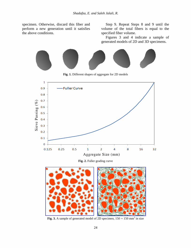
aggregate particles and fibers. In 2D
specimens, for a given type of angular
aggregate, the shape of which has been
prescribed (Figure 1), the major factors to be
considered in the generation of random
aggregate structure are the rotation, size, and
spatial distribution of the particles.
Meanwhile in 3D specimens with spherical
aggregate particles, random sizes and
positions of the particles should be taken
into consideration. For so doing, the random
sampling principle of Monte Carlo's
simulation method has been used, which is
done by taking samples of aggregate
particles from a source, whose size
distribution follows Fuller's grading curve
(Figure 2) and placing the aggregate
particles into the concrete one by one in such
a way that they will not overlap with the
particles, already placed, and the spatial
distribution is as macroscopically
homogeneous as possible. This method is
commonly called the take-and-place method
(Wang et al., 1999). The take-process and
place-process are performed concurrently in
the sense that a particle generated by the
take-process is immediately placed into the
concrete. They are conducted in a sequence,
starting with the largest size particles until
the last particle of the size range, then to be
repeated for successively-smaller size
particles, as it is generally easier to pack the
particles into the concrete in this way. After
random distribution of aggregate particles,
fibers are distributed randomly between
aggregate particles and within mortar in such
a way that they, too, will not overlap with
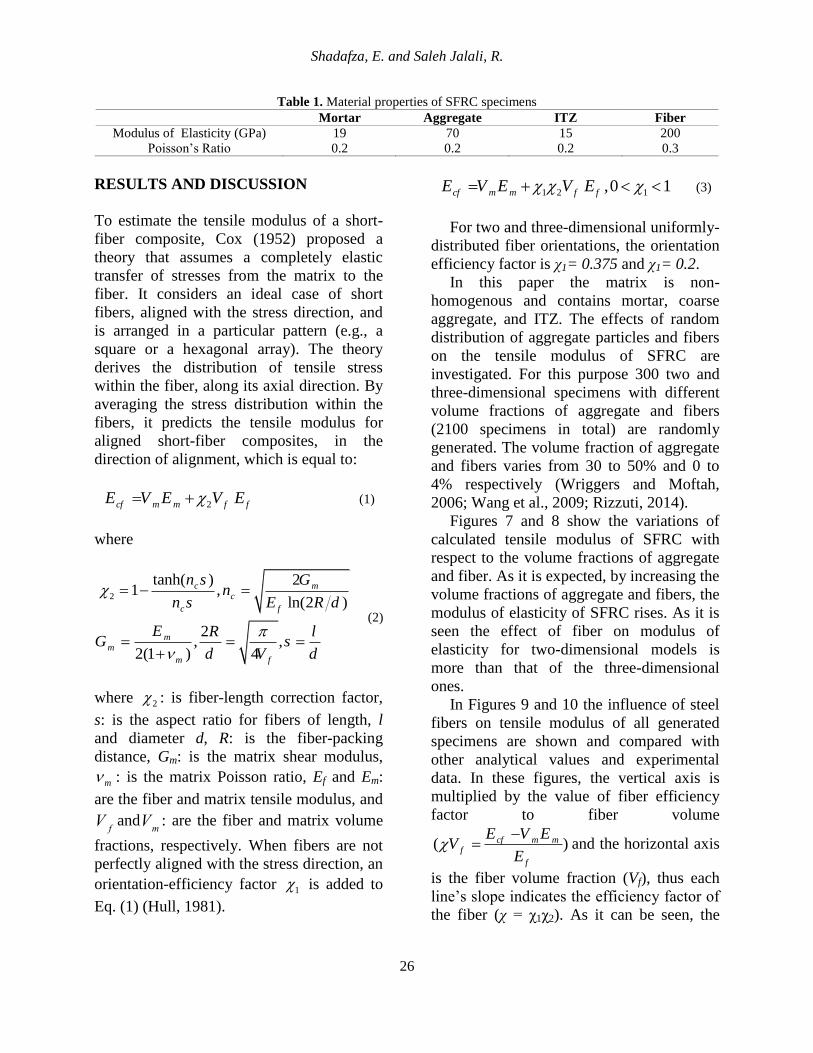
the aggregate particles, already placed. The
2D and 3D specimen size is 150150 mm2,
and 150150150 mm3, with the minimum
and maximum size of coarse aggregate,
assumed to be 8 and 20 mm; and the length
and diameter of steel fibers, taken to be 30
and 1.0 mm respectively. The taking and
placing process of aggregate particles and
fibers to generate random specimens is
summarized as follows:
Step 1. Calculate the volume of aggregate
to be generated in a certain grading segment.
Step 2. Randomly generate the position,
rotation, and diameter of aggregate particle
within the corresponding segment.
Step 3. Check to ensure that the generated
aggregate is within the specimen boundary
and does not overlap with other aggregate
particles that have been already placed in the
specimen. Otherwise, discard this aggregate
and perform a new generation until it
satisfies the above conditions.
Step 4. Repeat Steps 2 and 3 until the
volume of generated aggregate particles is
equal to the calculated volume of aggregate
for the specified grading segment.
Step 5. Repeat Steps 1 to 4 for all grading
segments.
Step 6. Calculate the quantity of fibers, in
accordance with the volume of fiber dosage.
Step 7. Generate the random fiber
position and orientation, and place the fiber
in the specimen.
Step 8. Check to ensure the fiber is
located within the specimen boundary and
does not overlap with aggregate particles
that have been already placed in the
Shadafza, E. and Saleh Jalali, R.
24
specimen. Otherwise, discard this fiber and
perform a new generation until it satisfies
the above conditions.
Step 9. Repeat Steps 8 and 9 until the
volume of the total fibers is equal to the
specified fiber volume.
Figures 3 and 4 indicate a sample of
generated models of 2D and 3D specimens.
Fig. 1. Different shapes of aggregate for 2D models
Fig. 2. Fuller grading curve
Fig. 3. A sample of generated model of 2D specimen, 150 150 mm2 in size

Civil Engineering Infrastructures Journal, 49(1): 21 – 32, June 2016
25
Fig. 4. A sample of generated model of 3D specimen, 150150150 mm
3 in size
Finite Element Model
In order to carry out a linear analysis of
the randomly-generated specimens under
direct tension, 2D and 3D models of SFRC
specimens are constructed and modeled in
ABAQUS. Modulus of elasticity and
Poisson’s ratio for elastic material property
of aggregate, mortar, ITZ, and steel fiber are
considered within the range of other studies’
assumptions, presented in Table.1 (Jing,
2011; Gal, 2011). Many researches have
been done to study the properties of ITZ but
this field is yet to be known thoroughly. The
thickness of the ITZ is about 0.05 mm
(Zheng, 2005) but due to computer-
processing time difficulties, it is considered
to be 1 mm. It is assumed that within the ITZ
area, the material properties are weaker than
the mortar matrix; however, in order to
compensate the increased thickness of ITZ,
the ITZ material is not considered quite
weaker than the mortar and is regarded as a
homogenized combination of mortar and
ITZ. ABAQUS’ auto-meshing with a
maximum size of 3 mm has been employed
to mesh the specimens that become finer
near the aggregate particles. Elements, used
for modeling aggregate, mortar, and ITZ, are
3-Node linear plane stress triangles (CPS3)
as well as 4-Node linear tetrahedrons
(C3D4) for 2D and 3D specimens,
respectively. Fibers are modeled by 2-Node
linear 2-D truss elements (2DT2) which are
embedded in mortar (Figures 5 and 6).
Fig. 5. 2D Finite Element model of SFRC specimen Fig. 6. 3D Finite Element model of SFRC specimen
Shadafza, E. and Saleh Jalali, R.
26
Table 1. Material properties of SFRC specimens
Mortar Aggregate ITZ Fiber
Modulus of Elasticity (GPa) 19 70 15 200
Poisson’s Ratio 0.2 0.2 0.2 0.3
RESULTS AND DISCUSSION
To estimate the tensile modulus of a short-
fiber composite, Cox (1952) proposed a
theory that assumes a completely elastic
transfer of stresses from the matrix to the
fiber. It considers an ideal case of short
fibers, aligned with the stress direction, and
is arranged in a particular pattern (e.g., a
square or a hexagonal array). The theory
derives the distribution of tensile stress
within the fiber, along its axial direction. By
averaging the stress distribution within the
fibers, it predicts the tensile modulus for
aligned short-fiber composites, in the
direction of alignment, which is equal to:
2cf m m f fE V E V E (1)
where
2
tanh( ) 21 ,
ln(2 )
2, ,
2(1 ) 4
c mc
c f
mm
m f
n s Gn
n s E R d
E R lG s
d V d
(2)
where 2 : is fiber-length correction factor,
s: is the aspect ratio for fibers of length, l
and diameter d, R: is the fiber-packing
distance, Gm: is the matrix shear modulus,
m : is the matrix Poisson ratio, Ef and Em:
are the fiber and matrix tensile modulus, and
Vf
andVm
: are the fiber and matrix volume
fractions, respectively. When fibers are not
perfectly aligned with the stress direction, an
orientation-efficiency factor 1 is added to
Eq. (1) (Hull, 1981).
1 2 1,0 1cf m m f fE V E V E (3)
For two and three-dimensional uniformly-
distributed fiber orientations, the orientation
efficiency factor is χ1= 0.375 and χ1= 0.2.
In this paper the matrix is non-
homogenous and contains mortar, coarse
aggregate, and ITZ. The effects of random
distribution of aggregate particles and fibers
on the tensile modulus of SFRC are
investigated. For this purpose 300 two and
three-dimensional specimens with different
volume fractions of aggregate and fibers
(2100 specimens in total) are randomly
generated. The volume fraction of aggregate
and fibers varies from 30 to 50% and 0 to
4% respectively (Wriggers and Moftah,
2006; Wang et al., 2009; Rizzuti, 2014).
Figures 7 and 8 show the variations of
calculated tensile modulus of SFRC with
respect to the volume fractions of aggregate
and fiber. As it is expected, by increasing the
volume fractions of aggregate and fibers, the
modulus of elasticity of SFRC rises. As it is
seen the effect of fiber on modulus of
elasticity for two-dimensional models is
more than that of the three-dimensional
ones.
In Figures 9 and 10 the influence of steel
fibers on tensile modulus of all generated
specimens are shown and compared with
other analytical values and experimental
data. In these figures, the vertical axis is
multiplied by the value of fiber efficiency
factor to fiber volume
( ) cf m mf
f
E V EV
E
and the horizontal axis
is the fiber volume fraction (Vf), thus each
line’s slope indicates the efficiency factor of
the fiber (χ = χ1χ2). As it can be seen, the

Civil Engineering Infrastructures Journal, 49(1): 21 – 32, June 2016
27
calculated values of the fiber efficiency
factor show some dispersion with a mean
value of µ and a standard deviation of σ(χ =
µ±σ). Also, other researcher’s
recommendations of fiber efficiency factor
have been shown with lines (the slope of
each line is the fiber efficiency factor value).
The fiber efficiency factors, suggested by
Teng et al. (2004) and Gal (2011) are equal
to 0.34 and 0.33, respectively, being very
close to the ones, proposed by Williamson
(1974) (χ = 0.35). Therefore these results
have been obviously eliminated from the
figure and the results of Williamson (1974)
represent those of Teng et al. (2004) and Gal
(2011).
Fig. 7. Tensile modulus of 2D specimens of SFRC with different volume fractions of aggregate and fibers
Fig. 8. Tensile modulus of 3D specimens of SFRC with different volume fractions of aggregate and fibers

Shadafza, E. and Saleh Jalali, R.
28
Fig. 9. Influence of steel fiber volume fraction on elastic modulus of 2D models
Fig. 10. Influence of steel fiber volume fraction on elastic modulus of 3D models
In Figure 9 for 2D models the mean
value of the calculated efficiency factor of
fiber is = 0.353 with a standard deviation
of σ = 0.024, which agrees with the
experimental results of Williamson (1974)
but surpasses those of Mori-Tanaka (1973),
and Ahmad and Lagoudas (1991). The mean
value is slightly larger than the value,
recommended by Hull (1981) for 2D
uniformly-distributed fibers ( = 0.323). In
Figure 10 for 3D models the mean value of
the calculated efficiency factor of fiber is

Civil Engineering Infrastructures Journal, 49(1): 21 – 32, June 2016
29
= 0.151 with a standard deviation of σ =
0.029, which agrees with the recommended
values of Ahmad and Lagoudas (1991) but is
smaller than the experimental values of
Williamson (1974) as well as those,
recommended by Mori-Tanaka (1973). What
is more, the mean value is in good
agreement with the recommended values of
Hull (1981) for 3D uniformly-distributed
fibers (χ = 0.149).
In Figures 11 and 12 compare the
calculated efficiency factor of fiber by finite
element analysis to the one, determined by
Eq. (3) and suggested by Hull (1981), for 2D
and 3D models, respectively. As it can be
seen in Figure 11, most of the points are
scattered above the bisector line, which
means that most of the calculated efficiency
factors by finite element analysis are larger
than those, suggested by Hull (1981) for 2D
models. In Figure 12, however, they are
below the bisector line, meaning that most of
calculated efficiency factors are smaller than
the suggested factors of Hull for 3D models.
This difference can be discussed, based on
the fact that based on the theory of Cox
(1952) and Hull (1981), the matrix was
supposed to be homogenous with only the
random orientation of fibers, taken into
considered. On the contrary, the matrix in
this study is non-homogenous, containing
mortar, coarse aggregate, and ITZ. So the
random orientation and position of aggregate
particles and fibers influence each other
simultaneously which scatters the calculated
factors with a standard deviation of 2.5% to
3.0% (for 150 mm cube specimens, while it
can vary with other specimens).
Nevertheless the mean value of the
calculated efficiency factor is in good
agreement with the value, recommended by
Hull (1981) for uniformly-distributed fibers.
Fig. 11. Comparison between calculated efficiency factors and those, determined by Eq. (3) and suggested by Hull
for 2D models

Shadafza, E. and Saleh Jalali, R.
30
Fig. 12. Comparison between calculated efficiency factors and those, determined by Eq. (3) and suggested by Hull
for 3D models
CONCLUSIONS
A sum of 2100 two and three-dimensional
specimens with different volume fractions of
aggregate and fiber have been generated by
random sampling principle of Monte Carlo's
simulation method, in which the commercial
code, ABAQUS, has been used to analyze
the specimens under tensile loading. Results
show that the non-homogeneity of the matrix
and random distribution of aggregate
particles and fibers lead to a dispersion of
calculated efficiency factors of fiber with a
standard deviation of 2.5% to 3.0%.
Nevertheless the mean value of the
calculated efficiency factor agrees with the
recommended value of Hull (1981) for
uniformly distributed fibers, and is equal to
0.353 and 0.151 for two and three-
dimensional models respectively.
REFERENCES
Ahmad, H.A. and Lagoudas, C.L. (1991). “Effective
elastic properties of fiber-reinforced concrete with
random fibers”, Journal of Engineering
Mechanics, 117(12), 2931-2938.
Bernardi, P., Cerioni, R. and Michelini, E. (2013).
“Analysis of post-cracking stage in SFRC
elements through a non-linear numerical
approach”, Engineering Fracture Mechanics, 108,
238-250.
Comby-Peyrot, I., Bernard, F., Bouchard, P., Bay, F.
and Garcia-Diaz, E. (2009). “Development and
validation of a 3D computational tool to describe
concrete behavior at meso-scale; application to the
alkali-silica reaction”, Computational Material
Science, 46, 1163-1177.
Cox, H.L. (1952). “The elasticity and strength of
paper and other fibrous materials”, British Journal
of Applied Physics, 3(3), 72-79.
Ding, Y. (2011). “Investigations into the relationship
between deflection and crack mouth opening
displacement of SFRC beam”, Construction and
Building Materials, 25(5), 2432-2440.

Civil Engineering Infrastructures Journal, 49(1): 21 – 32, June 2016
31
Gal, E. and Kryvoruk, R. (2011). “Fiber reinforced
concrete properties; a multiscale approach”,
Computers and Structures, 8(5), 525-539.
Grassl, P., Gregoire, D., Solano, L.R. and Pijaudier-
Cobat, G. (2012). “Meso-scale modeling of the
size effect on fracture process zone of concrete”,
International Journal of Solids and Structures,
49(13), 1818-1827.
Grassl, P. and Jirasek, M. (2010). “Meso-scale
approach to modeling the fracture process zone of
concrete subjected to uniaxial tension”,
International Journal of Solids and Structures,
47(13), 957-968.
Grassl, P. and Rempling, R. (2008). “A damage-
plasticity interface approach to the meso-scale
modeling of concrete subjected to cyclic
compressive loading”, Engineering Fracture
Mechanics, 75(16), 4804-4818.
Hao, Y.F., Hao, H. and Li, Z.X. (2009). “Numerical
analysis of lateral inertial confinement effects on
impact test of concrete compressive material
properties”, International Journal of Protective
Structures, 1(1), 143-145.
Hill, R. (1965). “A self-consistent mechanics of
composite materials”, Journal of Mechanics and
Physics of Solids, 13(4), 213-222.
Huang, Y., Yang, Z., Ren, W., Liu, G. and Zhang, C.
(2015). “3D meso-scale fracture modeling and
validation of concrete based on in-situ X-ray
Computed Tomography images using damage
plasticity model”, International Journal of Solids
and Structures, 67-68, 340-352.
Hull, D. (1981). An introduction to composite
materials, Cambridge University Press, London.
Hung, L.T., Dormieux, L., Jeannin, L., Burlion, N.
and Barthélémy, J.F. (2008). “Nonlinear behavior
of matrix-inclusion composites under high
confining pressure: application to concrete and
mortar”, Comptes Rendus Mecanique, 336(8),
670-676.
Islam, M., Khatun, S., Islam, R., Dola, J.F., Hussan,
M. and Siddique, A. (2014). “Finite Element
analysis of Steel Fiber Reinforced Concrete
(SFRC): Validation of experimental shear
capacities of beams”, Procedia Engineering, 90,
89-95.
Jing, Li., Lin-fu, W., Lin, J., Juan, L. and Hu, L.
(2011). “Numerical simulation of uniaxial
compression performance of big recycled
aggregate-filled concrete”, Electric Technology
and Civil Engineering (ICETCE) International
Conference, 1367-1370.
Kim, S.M. and Abu Al-Rub, R.K. (2010). “Meso-
scale computational modeling of the plastic-
damage response of cementitious composites”,
Cement and Concrete Research, 41(3), 339-358.
Mori, T. and Tanaka, K. (1973). “Average stress in
matrix and average energy of materials with
misfitting inclusions”, Acta Metallurgica, 21, 571-
574.
Nguyen, T.T.H., Bary, B. and Larrard, T. (2015).
“Coupled carbonation-rust formation-damage
modeling and simulation of steel corrosion in 3D
mesoscale reinforced concrete”, Cement and
Concrete Research, 74, 95-107.
Özcan, D. M., Bayraktar, A., Sahin, A., Haktanir, T.
and Tüker, T. (2009). “Experimental and Finite
Element analysis on the steel fiber-reinforced
concrete (SFRC) beams ultimate behavior”,
Construction and Building Materials, 23(2),
1064-1077.
Qin, C. and Zhang, C. (2011). “Numerical study of
dynamic behavior of concrete by meso-scale
particle element modeling”, International Journal
of Impact Engineering, 38(12), 1011-1021.
Rashid-Dadash, P. and Ramezanianpour, A.A.
(2014). “Hybrid fiber reinforced concrete
containing pumice and metakaolin”, Civil
Engineering Infrastructures Journal (CEIJ),
47(2), 229-238.
Rizzuti, L. (2014). “Effects of fibre volume fraction
on the compressive and flexural experimental
behaviour of SFRC”, Contemporary Engineering
Sciences, 7(8), 379-390.
Roubin, E., Colliat, J. and Benkemoun, N. (2015).
“Meso-scale modeling of concrete: A
morphological description based on excursion sets
of random fields”, Computational Materials
Science, 102, 183-195.
Salehian, H., Barros, J.A.O. and Taheri, M. (2014).
“Evaluation of the influence of post-cracking
response of steel fiber reinforced concrete (SFRC)
on load carrying capacity of SFRC panels”,
Construction and Building Materials, 73, 289-
304.
Shahabeyk, S., Hosseini, M. and Yaghoobi, M.
(2011). “Meso-scale Finite Element prediction of
concrete failure”, Computational Materials
Science, 50(7), 1973-1990.
Skarzynski, L. and Tejchman, J. (2010).
“Calculations of fracture process zones on meso-
scale in notched concrete beams subjected to
three-point bending”, European Journal of
Mechanics, 29(4), 746-760.
Smilauer, V. and Bazant, Z. (2010). “Identification of
viscoelastic C-S-H behavior in mature cement
paste by FFT-based homogenization method”,
Cement and Concrete Research, 40(2), 197-207.

Shadafza, E. and Saleh Jalali, R.
32
Smilauer, V. and Krejci, T. (2009). “Multiscale
model for temperature distribution in hydrating
concrete”, International Journal for Multiscale
Computational Engineering, 7(2), 135-151.
Sun, B., Wang, X. and Li, Z. (2015). “Meso-scale
image-based modeling of reinforced concrete and
adaptive multi-scale analyses on damage
evolution in concrete structures”, Computational
Materials Science, 110, 39-53.
Tailhan, J.L., Rossi, P. and Daviau-Desnoyers, D.
(2015). “Probabilistic numerical modeling of
cracking in steel fiber reinforced concretes”,
Cement and Concrete Composites, 55, 315-321.
Teng, T.L., Chu, Y.A., Chang, F.A., Shen, B.C. and
Cheng, D.S. (2007). “Development and validation
of numerical model of steel fiber reinforced
concrete for high-velocity impact”,
Computational Materials Science, 42(1), 90-99.
Teng, T.L., Chu, Y.A., Chang, F.A. and Chin, H.S.
(2004). “Calculating the elastic moduli of steel-
fiber reinforced concrete using a dedicated
empirical formula”, Computational Materials
Science, 31(3-4), 337-346.
Titscher, T. and Unger, J.F. (2015). “Application of
molecular dynamics simulations for the
generation of dense concrete meso-scale”,
Computers & Structures, 158, 274-284.
Ulm, F.J. and Jennings, H.M. (2008). “Does C-S-H
particle shape matter? A discussion of the paper
‘Modelling elasticity of a hydrating cement paste’,
by Julien Sanahuja, Luc Dormieux and Gilles
Chanvillard, CCR 37 (2007) 1427-1439”, Cement
and Concrete Research, 38(8), 1126-1129.
Wang, X., Yang, Z. and Jivkov, A.P. (2015). “Monte
Carlo simulations of mesoscale fracture of
concrete with random aggregate and pores: a size
effect study”, Construction and Building
Materials, 80, 262-272.
Wang, Z.L., Shi, Z.M. and Wang, J.G. (2011).
“Analysis of post-cracking stage in SFRC
elements through a non-linear numerical
approach”, Engineering Fracture Mechanics, 108,
238-250.
Wang, Z.L., Konietzky, H. and Huang, R.Y. (2009).
“Elastic-plastic-hydrodynamic analysis of crater
blasting in steel fiber reinforced concrete”,
Theoretical and Applied Fracture Mechanics,
52(2), 111-116.
Wang, Z.M., Kwan, A.K.H. and Chan, H.C. (1999).
“Mesoscopic study of concrete I: Generation of
random aggregate structure and Finite Element
mesh”, Computers and Structures, 70(5), 533-
544.
Williamson, G.R. (1974). “The effect of steel fibers
on the compressive strength of concrete”, ACI
Jouranl, 44, 195-208.
Wriggers, P. and Moftah, S.O. (2006). “Meso-scale
models for concrete: homogenization and damage
behavior”, Finite Elements in Analysis and
Design, 42(7), 623-636.
Wu, M., Chen, Z. and Zhang C. (2015). “Determining
the impact behavior of concrete beams through
experimental testing and meso-scale simulation: I.
Drop-weight tests”, Engineering Fracture
Mechanics, 135, 94-112.
Xu, Z., Hao, H. and Li, H.N. (2012a). “Meso-scale
modeling of dynamic tensile behavior of fiber
reinforced concrete with spiral fiber”, Cement and
Concrete Research, 42(11), 1475-1493.
Xu, Z., Hao, H. and Li, H.N. (2012b). “Meso-scale
modeling of fiber reinforced concrete material
under compressive impact loading”, Construction
and Building Materials, 26(1), 274-288.
Yazici, S., Arel, H.S. and Tabak, V. (2013). “The
effects of impact loading on the mechanical
properties of the SFRCs”, Construction and
Building Materials, 41, 68-72.
Zaitsev, Y.B. and Wittmann, F.H. (1981).
“Simulation of crack propagation and failure of
concrete”, Materials and Structures, 14(2), 357-
365.
Zhang, J. (2013). “Three-dimensional modelling of
steel fiber reinforced concrete material under
intense dynamic loading”, Construction and
Building Materials, 44, 118-132.
Zheng, J.J., Li, C.Q. and Zhou, X.Z. (2005)
“Thickness of interfacial transition zone and
cement content profiles between aggregates”,
Magazine of Concrete Research, 57(7), 397-406.
Zhou, X.Q. and Hao, H. (2009). “Mesoscale
modeling and analysis of damage and
fragmentation of concrete slab under contact
detonation”, International Journal of Impact
Engineering, 36(12), 1315-1326.
Zhou, X.Q. and Hao, H. (2008a). “Meso-scale
modeling of concrete tensile failure mechanism at
high strain rates”, Computers & Structures, 86(21-
22), 2013-2026.
Zhou, X.Q. and Hao, H. (2008b). “Modeling of
compressive behavior of concrete-like materials at
high strain rate”, International Journal of Solids
and Structures, 45(17), 4648-4661.