the effect of the additional magnetic …rrp.infim.ro/2015_67_3/a22.pdfand gas pressure on the...
TRANSCRIPT

Romanian Reports in Physics, Vol. 67, No. 3, P. 1004–1017, 2015
PLASMA PHYSICS AND APPLICATIONS
THE EFFECT OF THE ADDITIONAL MAGNETIC FIELD AND GAS PRESSURE ON THE SHEATH REGION OF A HIGH POWER IMPULSE MAGNETRON SPUTTERING DISCHARGE*
V. TIRON, I-L.VELICU, F. GHIORGHIU and G. POPA
“Alexandru Ioan Cuza University”, Faculty of Physics, Iasi, RO-700506, Iasi, Romania E-mail: [email protected]
Received July 31, 2013
Abstract. The influence of the both magnetic field strength and gas pressure on sheath properties in HiPIMS discharge was investigated in present work. Pulses with peak power density of about 3 kWcm-2 were applied to a planar circular unbalanced magnetron equipped with a Cu target, which operates in pure Ar gas at pressure range of 3 to 30 mTorr. The additional magnetic field (less as – 300 Gauss) in the magnetron target region was produced using an electromagnetic coil, while the sheath thickness and dynamics of plasma particles were studied using the fast imaging technique, time resolved – optical emission spectroscopy, emissive and electrical probes. The microstructure and morphology of the deposited films were investigated using X-ray diffractometer (XRD) and atomic force microscopy (AFM).
Key words: magnetron sputtering, thin films, additional magnetic field, cathode sheath.
1. INTRODUCTION
In magnetron sputtering process, the cathode sheath is the most important part of the discharge because in this region ions are accelerated towards the cathode, causing the target material sputtering [1]. The structure of the sheath, more specific potential distribution, depends on the both strength and configuration of magnetic field lines (i.e. balanced or unbalanced magnetron), working gas nature and pressure, discharge voltage and target material. The potential drop across cathode sheath and hence energy of the particles bombarding the target surface depends also on the excitation mode of the discharge as: dc, rf or pulsed magnetrons [2]. In High Power Impulse Magnetron Sputtering (HiPIMS), a high fraction of depositing flux of sputtered particles is ionized [3] and consequently, the magnetic filed geometry has an important role on sputtering rate, transport and deposition of sputtered material. Moreover, knowledge of the cathode sheath
* Paper presented at the 16th International Conference on Plasma Physics and Applications, June 20–25, 2013, Măgurele, Bucharest, Romania.
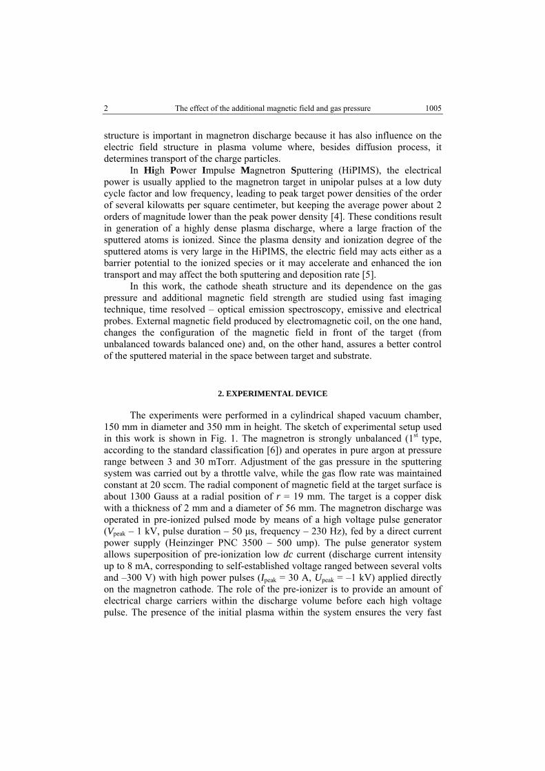
2 The effect of the additional magnetic field and gas pressure 1005
structure is important in magnetron discharge because it has also influence on the electric field structure in plasma volume where, besides diffusion process, it determines transport of the charge particles.
In High Power Impulse Magnetron Sputtering (HiPIMS), the electrical power is usually applied to the magnetron target in unipolar pulses at a low duty cycle factor and low frequency, leading to peak target power densities of the order of several kilowatts per square centimeter, but keeping the average power about 2 orders of magnitude lower than the peak power density [4]. These conditions result in generation of a highly dense plasma discharge, where a large fraction of the sputtered atoms is ionized. Since the plasma density and ionization degree of the sputtered atoms is very large in the HiPIMS, the electric field may acts either as a barrier potential to the ionized species or it may accelerate and enhanced the ion transport and may affect the both sputtering and deposition rate [5].
In this work, the cathode sheath structure and its dependence on the gas pressure and additional magnetic field strength are studied using fast imaging technique, time resolved – optical emission spectroscopy, emissive and electrical probes. External magnetic field produced by electromagnetic coil, on the one hand, changes the configuration of the magnetic field in front of the target (from unbalanced towards balanced one) and, on the other hand, assures a better control of the sputtered material in the space between target and substrate.
2. EXPERIMENTAL DEVICE
The experiments were performed in a cylindrical shaped vacuum chamber, 150 mm in diameter and 350 mm in height. The sketch of experimental setup used in this work is shown in Fig. 1. The magnetron is strongly unbalanced (1st type, according to the standard classification [6]) and operates in pure argon at pressure range between 3 and 30 mTorr. Adjustment of the gas pressure in the sputtering system was carried out by a throttle valve, while the gas flow rate was maintained constant at 20 sccm. The radial component of magnetic field at the target surface is about 1300 Gauss at a radial position of r = 19 mm. The target is a copper disk with a thickness of 2 mm and a diameter of 56 mm. The magnetron discharge was operated in pre-ionized pulsed mode by means of a high voltage pulse generator (Vpeak – 1 kV, pulse duration – 50 μs, frequency – 230 Hz), fed by a direct current power supply (Heinzinger PNC 3500 – 500 ump). The pulse generator system allows superposition of pre-ionization low dc current (discharge current intensity up to 8 mA, corresponding to self-established voltage ranged between several volts and –300 V) with high power pulses (Ipeak = 30 A, Upeak = –1 kV) applied directly on the magnetron cathode. The role of the pre-ionizer is to provide an amount of electrical charge carriers within the discharge volume before each high voltage pulse. The presence of the initial plasma within the system ensures the very fast

1006 V. Tiron et al. 3
rise time and high replication of the discharge current intensity when high voltage pulse is applied on the cathode [7].
In order to study the influence of the magnetic field strength on the cathode sheath region, a coaxially-mounted electromagnetic coil having 400 turns of a copper wire was used. The coil has cylindrical shape with inner diameter of 160 mm, outer diameter 220 mm and a height of 30 mm. When coil is fed by electrical current it generates a magnetic field opposing the field from the central pole of the magnetron. This supplementary magnetic field weakens the magnetic field strength of the central pole and raises the magnetic field strength of the outer pole, shifting the magnet filed structure towards a balanced magnetic trap in front of the target. The center of the coil corresponds with the center of the target surface (Fig. 1). The magnetic field strength created by the electromagnetic coil was measured by means of a Hall probe on magnetron axis. The magnetic field strength was changed from 0 to 300 Gauss by controlling the coil current intensity up to 10 A.
Fig. 1 – Experimental setup.
Information on ion flux distribution at the substrate region was obtained using a cold electrostatic probe system, which consists of eight coaxially ring shape probes made of tungsten wire of 2 mm diameter, axially placed in a distance of 8 cm from the cathode surface. For the sake of simplicity, in Fig. 1 only four probes

4 The effect of the additional magnetic field and gas pressure 1007
are presented. The diameters of the ring probes were ranged from 13 mm to 120 mm. Each probe was biased to –100 V with respect to ground anode potential so that temporal evolution of the ion saturation current during the pulse was recorded. The ion current was recorded using the voltage drop on a resistor of 50 ohm. The data for all probes were simultaneously recorded and stored in a 64-channel digital storage oscilloscope National Instruments PXI-8105, equipped with eight channel digitizer cards NI PXI-6133 – 64MSamples, with a maximum sampling rate of 1 MS/second per channel, operated under NI LABVIEW virtual instrument software.
The experimental data about plasma composition and temporal evolution of argon and copper spectral lines intensities during the pulse discharge were obtained by the time resolved-optical emission spectroscopy (TR-OES) and fast imaging. The high density plasma region in front of the cathode was monitored through a quartz window mounted in front of the target using an optical fiber which guides the light to a monochromator having a photomultiplier as detector. All electrical signals (discharge current and voltage waveform, time evolution of the spectral line intensities and plasma potential) were recorded and stored by a digital oscilloscope (Le Croy WaveSurfer 434). The time-resolved fast imaging technique was used for finding spatial distribution at certain instant time of the Ar excited species in a high-power short-pulse magnetron discharge. The side-view images of the HiPIMS discharge were registered with the fast ICCD camera (Hamamatsu), using an exposure gate of 30 ns. The space-and-time evolution of argon excited species was registered using optic-selective filter with transmission band from 695 nm to 1100 nm. In order to prevent the saturation of the camera detector, the light coming from high density plasma region was attenuated using an additional neutral optical filter with 1 % transmittance.
Measurements of plasma potential were carried out with the help of an emissive probe. The emissive probe consists of thoriated tungsten wire of 0.2 mm diameter and 3 mm length, fitted into two bore ceramic tubes provided with copper connecting wires. The plasma exposed tungsten wire has cylindrical shape and its axis was orientated parallel to the target surface, respectively. In order to avoid the ground loops and unwanted electrical noises in the circuit, the emissive probe was heated using an insulated battery driven electronic circuit, which adjusted very accurately the heating current of the probe. The plasma potential was measured as probe floating potential when emissive probe was heated up to thermal electron emission [8].
The microstructure and morphology of the deposited films were investigated using X-ray diffractometry (XRD) and atomic force microscopy (AFM), while the thickness of the deposited films was measured by means of interferometric method.

1008 V. Tiron et al. 5
3. RESULTS AND DISSCUSIONS
The discharge voltage and current waveforms with and without additional external magnetic field are shown in Fig. 2. The discharge was operated with process parameters of 50 µs pulse duration, 230 Hz pulse repetition frequency and –900V charging voltage at 10 mTorr argon pressure. The discharge voltage and the discharge current were measured using a 1:100 voltage probe and a 1:10 current probe, respectively. The waveforms time evolution present all three phases described as: a) pre-ionization phase (before applying the pulse t < 0), b) power pulse on-phase (t = 0–50 µs) and c) afterglow plasma. When t > 1 ms, the afterglow plasma gradually transforms to the pre-ionization plasma. The pre-ionization phase is characterized by a self-sustaining voltage of –200–300 V and a low current of the order of few mA. During the pulse, the discharge current develops to a peak of 20 A, in absence and 30 A, respectively, in presence of the external magnetic field B = 150 Gauss. Moreover, the voltage on pulse attains a steady state of –700 V in absence and –500 V, respectively, in the presence of the external magnetic field.
Fig. 2 – Temporal evolution of the voltage (a) and current (b) on pulse with and without external
magnetic field, respectively.
Approximately 15 µs after pulse ignition the discharge current intensity starts to decrease due to: i) rarefaction of the buffer gas produced by the sputtered atoms wind [9] and ii) self-sputtering regime which determines the decreasing of the target sputtering rate and decreasing of the secondary electron emission coefficient [10]. During the high power pulse the plasma composition is changed and it evolves from dominant gas sputtering to metal self-sputtering mode [11].
Therefore, external magnetic field changes significantly the electrical parameters of the discharge. A stronger magnetic field results in a better confinement of the electrons and decrease of the discharge voltage and an increase of the average discharge current intensity. The effect of the magnetic field on the
6 The effect of the additional magnetic field and gas pressure 1009
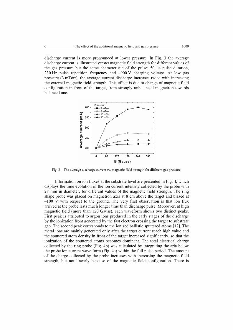
discharge current is more pronounced at lower pressure. In Fig. 3 the average discharge current is illustrated versus magnetic field strength for different values of the gas pressure but the same characteristic of the pulse: 50 µs pulse duration, 230 Hz pulse repetition frequency and –900 V charging voltage. At low gas pressure (3 mTorr), the average current discharge increases twice with increasing the external magnetic field strength. This effect is due to change of magnetic field configuration in front of the target, from strongly unbalanced magnetron towards balanced one.
Fig. 3 – The average discharge current vs. magnetic field strength for different gas pressure.
Information on ion fluxes at the substrate level are presented in Fig. 4, which displays the time evolution of the ion current intensity collected by the probe with 28 mm in diameter, for different values of the magnetic field strength. The ring shape probe was placed on magnetron axis at 8 cm above the target and biased at –100 V with respect to the ground. The very first observation is that ion flux arrived at the probe lasts much longer time than discharge pulse. Moreover, at high magnetic field (more than 120 Gauss), each waveform shows two distinct peaks. First peak is attributed to argon ions produced in the early stages of the discharge by the ionization front generated by the fast electron crossing the target to substrate gap. The second peak corresponds to the ionized ballistic sputtered atoms [12]. The metal ions are mainly generated only after the target current reach high value and the sputtered atom density in front of the target increased significantly, so that the ionization of the sputtered atoms becomes dominant. The total electrical charge collected by the ring probe (Fig. 4b) was calculated by integrating the aria below the probe ion current wave form (Fig. 4a) within the full pulse period. The amount of the charge collected by the probe increases with increasing the magnetic field strength, but not linearly because of the magnetic field configuration. There is

1010 V. Tiron et al. 7
pronounced jump for probe current when magnetic field strength increases from 120 Gauss to 180 Gauss. By increasing the external magnetic strength from 0 Gauss to 300 Gauss, the average current increases only with 20 percent, while the probe current increases more than 8 times.
Fig. 4 – Temporal evolution of the probe current (a) and integrated probe current vs. magnetic field strength (b).
The radial distribution of the ion current density is more pronounced in the presence of the external magnetic field and shows a linear decreasing from magnetron axis toward the lateral chamber walls.

8 The effect of the additional magnetic field and gas pressure 1011
Fig. 5 – Radial distribution of integrated probe current vs. magnetic field strength measured
at 8 cm above the target.
The influence of the external magnetic field on plasma parameters can be highlight by the optical emission spectroscopy. In Fig. 5, time evolution of the argon (λ = 750.38 nm) and copper (λ = 521.82 nm) spectral line versus magnetic field strength are illustrated. The argon spectral line intensity is always the first to rise as the argon atoms are always present in the discharge volume and are excited by the highly energetic electrons at the beginning of the pulse. The spectral line intensity of excited argon atoms lasts much longer time than discharge pulse. The copper spectral lines intensity has the same evolution as the discharge current intensity: a slow increase during ignition of the pulse, followed by a slight decrease during the entire pulse and fast decay after the pulse. This is an expected evolution since copper is sputtered from the target by ion bombardment and the discharge current intensity measured at the cathode is carried out by the ions [13]. Again, there is a jump in temporal evolution of argon and copper spectral line intensity with increasing external magnetic field strength between 120 and 180 Gauss. Moreover, for B higher than 180 Gauss, neutral copper spectral line intensity tends to decrease. That decrease is due to the ionization processes (a part of the sputtered neutral atoms are ionized in the plasma volume) and due to changing of the magnetic trap. By increasing the external magnetic field the sheath region in front of the target becomes wider and plasma potential distribution inside the magnetic trap is changed. The electrical field within the cathode sheath becomes lower and, on a hand, a large fraction of the ionized sputtered particles can escape from magnetic trap, on the other hand, the energy of the argon ions arriving at the target will be lower, causing a lower sputtering rate.

1012 V. Tiron et al. 9
Fig. 6 – Temporal evolution on pulse of Argon (a) and Copper (b) spectral line vs. magnetic field strength.
This interpretation is also sustained by the side view images of the discharge registered at 2 µs after ignition of the pulsed discharge with a fast ICCD camera, using an exposure gate of 30 ns. During the ignition phase, neutral working gas emission dominates the developing discharge due to collisional excitations by fast electrons emitted from the cathode. The space-and-time evolution of argon excited species was registered using optic-selective filter with transmission band from 695 nm to 1100 nm. In this wavelength range, the optical emission spectra of the plasma is given only by the neutral argon excited species. The spatial development of the excited argon is due to spatial distribution of the fast electrons which is strongly related to the unbalanced magnetic field distribution having larger

10 The effect of the additional magnetic field and gas pressure 1013
magnetic field strength on axial direction (2900 Gauss) and rather weak magnetic field strength outside polar piece (300 Gauss also in axial direction). These results confirm the fact that during the initial phase of the pulse the fast electrons and buffer gas atoms excitation and ionization collisions are dominant.
Comparison between ICCD images of the plasma shows that the spatial distribution of the Ar excited atoms is strongly influenced by the magnetic field configuration. Increasing the external magnetic field strength, the light emitted by excited gas due to fast electrons traveling the space between the electrodes changed from a truncated conical shape (B = 120 Gauss) to a conical one (B = 180 Gauss).
Fig. 7 – Fast-pulse ICCD images registered with red optical filters.
B = 0 Gauss B = 60 Gauss
B = 120 Gauss B = 180 Gauss
B = 300 Gauss B = 180 Gauss p = 3 mTorr

1014 V. Tiron et al. 11
Visually, the increase of the external magnetic field strength is accompanied by a compression of the magnetic trap in radial direction and its expansion in axial direction. By changing the magnetic field configuration, electrons are forced to move on axis of the magnetron system, limiting their lateral mobility. The applied magnetic field acts like a focusing lens for the electrons. Because of necessity of maintenance of the plasma quasi-neutrality, the ions are forced to move together with electrons, preventing their drift in radial direction. Moreover, there is a clear delimitation between target and intensive light coming from magnetic trap region (picture corresponding to B = 300 Gauss), which highlights the sputtering “wind” effect. For lower gas pressure (3 mTorr), the light intensity is lower and sheath region has a cylindrical shape and expand more in front of the target.
Fig. 8 – Temporal evolution of plasma potential vs. magnetic field strength (a) and axial distribution
(b) of plasma potential for B = 0 Gauss and B = 150 Gauss.

12 The effect of the additional magnetic field and gas pressure 1015
The temporal and spatial evolution of the plasma potential along a line parallel to the axis (Oz) of the system from the target surface to substrate above the race-track was monitored using an emissive probe with 10 ns time-resolution. Fig. 8a illustrates the time evolution of the plasma potential during the pulse measured for different value of the magnetic field strength at 8 cm above the race-track. The time evolution of the plasma potential shows four phases, labelled in Fig. 8a as: a) – preionization phase; b) – “on-phase” start; c) – “on-phase” end; d) – “off-phase”.
The measurements performed during the pulse show a highly dynamics nature of the plasma potential, with negative values up to –100 V at 2 mm distance from cathode and large gradients of the plasma potential within the magnetic trap region in the first 2 or 3 µs after the ignition of the discharge pulse. The highly negative plasma potential might be a result of super-thermal or beam-like electrons with mean kinetic energy up to 100 eV [14]. The high-energy electrons created in this stage are important in the electron impact ionization mechanism to generate the dense plasma during the HiPIMS pulse. There is a slight delay (~1 µs) between discharge voltage peak and the plasma potential structure formation in the bulk trapped plasma. The large gradient of the plasma potential reveals large axial electric fields, which, close to the target, which can reach intensities of the order 15 kVm–1. The large axial electric field developed in the early stage of the pulse accelerates the present argon ions produced close to the target in the pre-ionization phase, towards the cathode, initiating the both sputtering and secondary electron emission. This process makes possible very fast onset of the high power pulse and rapid increase of the discharge current intensity. The plasma potential is always negative during the on-pulse and their spatial structure in magnetic trap region provides a large potential barrier for the sputtered ionized species, avoiding their transport to the substrate and lowering the deposition rate. The sputtered ionized species are back attracted to the target by the large axial electric field and strongly accelerated in the cathode fall, thereby initiating the self-sputtering regime. Metal ions returning back to the target can further decrease the deposition rate due to the low value of the self-sputtering yield. Therefore, the positive ions produced outside the magnetic trap will “see” a weak axial electric field directed to both discharge chamber but mainly to negatively biased substrate. Moreover, at the early stage of the pulse discharge, the ion plasma composition outside the magnetic trap is dominated by the argon ions. The plasma potential (corresponding to “on-phase” start peak) versus axial distance from cathode surface is presented in Fig. 8-b, for pulse durations of 50 µs and gas pressure 10 mTorr. When magnetron operates without additional external magnetic field, the axial distribution of plasma potential, inside the magnetic trap region (z < 1cm), shows a large potential drop (from –87 V to –27 V). Outside magnetic trap region (1 cm < z < 10 cm) the plasma potential increases very slowly with the distance and the axial electric field within the plasma region is very weak (E ~ 10 Vm–1). In presence of the external

1016 V. Tiron et al. 13
magnetic field, the axial distribution of the plasma potential in front of the race track is very different. It shows a “wave like” spatial structure, which correspond to a sequence of plasma double layers with larger gradients of the plasma potential close to the target [15].
The microstructure and morphology of the deposited films were investigated using X-ray diffractometry (XRD) and atomic force microscopy (AFM). Thin films with improved quality (a better uniformity of the deposited thin film thickness, smoother surface and higher degree of crystalline phase) were obtained in the presence of the external magnetic field. The deep film structure analysis is not the subject of the present work.
4. CONCLUSIONS
The external additional magnetic field acts mainly on the electrons diminishing their loss at the chamber walls and enhancing ionization process of sputtered atoms. Moreover, it allows a better transport of the ion flux towards substrate. Applying an additional magnetic field, the cathode sheath width increases with magnetic field strength. A stronger magnetic field results in a better confinement of the electrons and decrease of the discharge voltage and increase of the average discharge current intensity. The discharge voltage increases with decreasing pressure due to increasing of the primary electrons recapture by the target.
The spatial distribution of plasma composition was significantly changed when the magnetron operates with additional external magnetic field. The results show that the presence of an additional magnetic field in the cathode region can change not only the sheath properties, but it may also strongly influence both ionization and transport processes of the particles improving the thin films properties.
Acknowledgments. This work was financially supported by Partnerships Program, under grant PN-II-PT-PCCA-2011-3.2-1340, no. 174/2012.
REFERENCES
1. E. Bultinck and A. Bogaerts, J. Phys. D: Appl. Phys., 41, 202007 (2008). 2. Klaus Ellmer, J. Phys. D: Appl. Phys. 33, R17–R32 (2000). 3. J. Bohlmark, M. Ostbye, M. Lattemann, H. Ljungcrantz, T. Rosell and U. Helmersson, Thin Solid
Films, 515, 1928 (2006). 4. J.T. Gudmundsson, N. Brenning, D. Lundin and U. Helmersson, J. Vac. Sci. Technol., A 30,
030801 (2012). 5. A. Mishra, P.J. Kelly and J.W. Bradley, Plasma Sources Sci. Technol., 19, 045014 (2010). 6. B. Window and N. Savvides, J. Vac. Sci. Technol A, 4, 3, 453 (1986). 7. S. Konstantinidis, J. P. Dauchot, M. Ganciu and M. Hecq, J. Appl. Phys., 99, 013307 (2006).

14 The effect of the additional magnetic field and gas pressure 1017
8. E.Y. Wang, N. Hershkowitz, T. Intrator and C. Forest, Rev. Sci. Instrum., 57, 2425 (1986). 9. S. M. Rossnagel, J. Vac. Sci. Technol. A, 6, 19 (1988).
10. A. Anders, J. Andersson and A. Ehiasarian, J. Appl. Phys., 102, 113303 (2007). 11. A. Anders, Surf. Coat. Technol., 204 2864 (2010). 12. K. Macák, V. Kouznetzov, J.M. Schneider, U. Helmersson and I. Petrov, J. Vac. Sci. Technol. A,
18, 1533 (2000). 13. C. Costin, V. Tiron and G. Popa, IEEE Trans. Plasma Sci., 39, 2482 (2011). 14. P. Poolcharuansin, J.W. Bradley, Surf. Coat. Technol., 205, S307 (2011). 15. B. Song, R.L. Merlino and N. D’Angelo, Physica Scripta, 45, 395 (1992).