the effect of selected welding parameters on properties of
TRANSCRIPT

73Przegląd sPawalnictwa Vol. 86 nr 11/2014
the effect of selected welding parameters on properties of Fsw welded joints in ferritic steel type s235 Jrc+n
Wpływ wybranych parametrów zgrzewania tarciowego z przemieszaniem na właściwości złączy stali S235JRC+N
Peter ZifčákPeter BlažíčekPeter Pastier
P. Zifčák, Ph.D. (Mech. Engin.); P. Blažíček, Ing.; P. Pastier, Ing. – welding Research Institute – Industrial Institute of SR, Račianska, 71, 832 59 Bratislava, Slovak Republic
Autor korespondencyjny/Corresponding author: [email protected]
abstractThis work presents the results of welding ferritic steel
type S235 JRC, 5 mm in thickness, welded by friction stir welding (FSw) process. The aim of study was to demon-strate the effect of selected welding parameters as tool material (tungsten carbide- wC, or silicon nitride – Si3n4), welding speed, tool rotation speed on the properties of welded joints and the life of welding tools. The prop-erties of welded joints were assessed visually, by ra-diography – RT inspection, mechanical tests and by observations of macro- and micro-structure. The life of welding tools was expressed by mass losses and also by the change in shoulder diameter and change in pin length in dependence on weld length. welding with wC tools was shown as unstable regarding the low dimen-sional stability of welding tool. On contrary, welding with ceramic tools permits formation of sound welds fabricated within optimum welding parameters with rotation speed 500 RPM and welding speed 50 to 100 mm/min. The best life of ceramic tools is achieved at rotation 400 RPM and welding speed 50 mm/min. However, at application of these parameters 100 % soundness of welds over en-tire weld length was not achieved.
Keywords: friction stir welding, steel, welding param-eters, tool lifetime
Streszczeniew artykule zaprezentowano wyniki zgrzewania (FSw) stali S235 JRC+n o grubości 5 mm. Celem opisanego ekperymentu eksperymentu było określenie wpływu wy-branych zasadniczych parametrów procesu: materiał narzędzia (wC i Si3n4), prędkość zgrzewania oraz pręd-kość obrotowa narzędzia, na właściwości otrzymywanych złączy oraz na trwałość narzędzia zgrzewającego. Złącza badano metodami nieniszczącymi wizualnie i z użyciem radiografii oraz metodami niszczącymi w celu określenia właściwości mechanicznych i scharakteryzowania mikro i makrostruktury. Trwałość narzędzia (trzpienia zgrze-wającego) określano poprzez pomiar ubytku jego masy i charakterystycznych właściwości geometrycznych (pro-mień i długość trzpienia). narzędzie wykonane z wC wy-kazało niską trwałość i stabilność wymiarową. narzędzie z ceramiki Si3n4 umożliwia uzyskiwanie dobrych zgrzein z blisko optymalną prędkością 500 obr/min. i prędkością zgrzewania 50 do 100 mm.min. Przy czym, największą trwałość narzędzia uzyskano dla prędkości 400 obr/min. i prędkości zgrzewania 55 mm/min. jednak wtedy nie uzy-skano w 100% prawidłowego połączenia.
Słowa kluczowe: zgrzewanie tarciowe z przemiesza-niem, stal, parametry zgrzewania, trwałość narzędzia

74 Przegląd sPawalnictwa Vol. 86 nr 11/2014
IntroductionFriction stir welding was initially developed for weld-
ing non-ferrous metals as aluminium, magnesium, cop-per and their alloys. The driving force of great interest in commercial utilisation of this technology consists mainly in absence of melt during welding process. This means that the problems typical for fusion meth-ods of welding, as the occurrence of hot and liqua-tion cracks, pores and loss of alloying elements are actually eliminated in case of friction stir welding [1]. The inner structure of metal, precisely elaborated by the manufacturing technologies of base metals is thus considerably less disrupted. Also other advantages, related either to higher quality of welds, improved welder´s safety and life environment protection are fur-ther accompanying features of this fact. Key element of success with this technology consists in welding tool. welding tool is usually composed of a shoulder and a pin. welding tool is during welding process exposed to wear, high stresses and temperatures. This is true mainly in case of welding materials with melting point over 1000 ºC [2,3]. Commercial weld-ing of such materials is limited owing to high costs and poor life of welding tools. The development in the field of welding tool is at present oriented to wRe (w-25%Re) and PCBn materials. Rhenium is a pre-cious metal and therefore the semiproduct for manu-facture of welding tool is thus costly. On the other hand PCBn material is accessible, but owing to its high hard-ness it is hard machinable and therefore also rather costly [1]. The life of tools made of the mentioned materials varies in order of tens meters of fabricated welds with plate thickness up to 6 mm [4]. Besides the tool material also its geometry is of great importance. It is in principle valid that the more intricate pin geom-etry in the form of flats, threads and grooves favour-ably affects the formation and soundness of welds. The mentioned geometrical peculiarities of the tool are nullified due to effect of wear (abrasive, diffusive) acting during the welding process. This means that the tool geometry is getting smoother during welding up to the so-called self-forming shape, which resem-bles the tool with a smooth conical pin [5,6].
The welding tools with a simple shape and afford-able priced were selected with the aim to identify the affect of the main welding parameters (rotation speed, welding speed) on the properties of welds fabricated
table I. Measured chemical composition of S 235 JRC+n steel together with the values of material certificatetablica I. Skład chemiczny zastosowanej do badań stali S 235 JRC+n, zarejestrowany oraz według normy
Fig. 1. welding tool geometryRys. 1. Geometria narzędzia zgrzewającego
in ferritic steel type S235 JRC+n. Based on the men-tioned literature sources the tool geometry with a con-vex shoulder and conical pin was selected. welding tools were made of relatively machinable materials as tungsten carbide (wC) and silicon nitride Si3n4.
The results presented in this work may be more or less applied for all ferritic steels. naturally, welding of high strength steels would require greater compres-sive forces, especially in the cases where the strength is achieved by alloying. These forces will subsequently exert in greater wear of welding tool.
ExperimentalFerritic steel S 235 JRC+n with dimensions
5 x 150 x 400 mm and guaranteed weldability was used for welding experiments. The chemical composition of this steel is given in Table I.
welding tool with geometry shown in Fig. 1 was used, made of two types of materials namely wC (tungsten carbide) and Si3n4 (ceramic material – silicon nitride).
welding experiments with wC welding tool were made at constant rotation speed 400 RPM and welding speeds 50, 100, 150, 200 and 250 mm/min. welding experiments with Si3n4 were performed with spindle rotation 350, 400, 500 RPM and welding speeds 30, 50, 100 mm/min.
The tool life was assessed by welding tool mass loss due to welding. For this purpose, the weight of tool prior to and after welding was measured by means of labo-ratory scales. In addition also the welding tool geom-etry prior to and after welding was measured by use
ContentHm. % / wt %
C Mn Si P S
Measured values 0,146 0,647 0,017 0,011 0,0096
S235 JRC+n - certificate max. 0,17 max. 1,4 max. 0,03 max. 0,035 max. 0,05

75Przegląd sPawalnictwa Vol. 86 nr 11/2014
of a digital slide ruller. Following tool parameters were measured:– Pin length calculated as L1 – L2, where L1
is the overall length of welding tool and L2 is the tool length without pin (Fig. 1),
– Shoulder diameter of welding tool, ø 20 mm prior to welding and after welding (Fig. 1).Cross sectional scheme of welded joint for the pur-
pose of its assessment by mechanical tests as uniaxial tension, bend test, impact bend test and metallographi-cal examination is shown in Fig. 2.
In case of uniaxial tensile test three test pieces of each welded joint were tested, designated as A, E, K, as shown in the cross sectional scheme (Fig. 2). Bend of test pieces was performed in weld axis, namely from its upper side (pieces B, D) and also from the root side (pieces H, J) on a mandrel with 4t diameter (t – material thickness). Impact bend test of stirred zone was per-formed on test pieces C, F, G, I (Fig. 2) with „V“ notch.
Fig. 2. Sectional plan of welded joint for the purpose of preparation of test specimensRys. 2. Plan cięcia złącza spawanego w celu przygotowania próbek testowych
Macro - and micro-structure was observed on speci-mens cut in transverse direction to welding axis (Fig. 2). The specimens were prepared by grinding, mechanical polishing and chemical etching in 4 % nital.
Hardness of welded joint was measured by Vick-ers method at 9.81 n (HV1) load. Measurement was carried out on metallographically prepared cross sec-tions of “Macro” specimens cut in transverse direction to welding axis. About 50 indents were performed with about 0.5 mm spacing on metallographically prepared cross sections.
Experimental - Welding with tungsten carbide tools
First welding experiments were carried out with appli-cation of wC (tungsten carbide) welding tools at con-stant rotation speed 400 RPM and welding speeds 50, 100, 150, 200 and 250 mm/min. Depending on actual
case, either visual inspection or RT test have revealed a void (channel) formed along entire weld length on its advancing side (AS). The void (channel) comes out to outer weld surface at welding speed over 200 mm/min (Fig. 3). In case of welding with slower speed 150 mm/min the void is enclosed, however it is prop-agating on the advancing side of the weld (Fig. 4). Metallographic cross section has shown that the void is located closer to weld root, namely on the stir zone periphery at AS (Fig. 5). In case of welding with lower speeds 100 and 50 mm/min the first half of the weld is homogeneous, whereas a continuous void again occurs in the second half of the weld, as documented by the radiogram from RT test of welded joint (Fig. 6).
Fig. 3. Overall view on the surface of welded joint, 400 RPM 200 mm/minRys. 3. widok ogólny złącza zgrzewanego od strony lica (parametry zgrzewania: 400 obr/min. 200 mm/min)
Fig. 4. Overall view on welded joint (400 RPM, 150 mm/min) - upper picture, RT rediogram of welded joint - lower pictureRys. 4. widok ogólny złącza zgrzewanego od strony lica (parametry zgrzewania: 400 obr/min. 150 mm/min) – góra, radiogram RT złącza – dół
Fig. 5. Enclosed void propagating over entire weld length on its ad-vancing side metallographic cross section in Y, Z planeRys. 5. Zamknięta wada występująca na całej długości zgrzeiny, zgład metalograficzny w płaszczyźnie Y, Z

76 Przegląd sPawalnictwa Vol. 86 nr 11/2014
Fig. 6. RT radiogram of welded joint - 400 RPM, 100 mm/minRys. 6. Radiogram złącza zgrzewanego (parametry zgrzewania: 400 obr/min. 100 mm/min)
Similar type of defect was observed also in case of welding Al alloys, where their microstructure is not subjected to polymorphous transformation and only grain recrystallization takes place. This means that the traces after material flow and stirring are more readable for understanding the causes of formation of the mentioned voids. By the study [7,8] the voids were formed on the boundary of two zones where welding material is flowing in opposite direction. One material flow is oriented in the onion ring, where ma-terial flows in a whirl in welded material thickness (plane Y, Z). The primary source of such material flow is a rotating tool pin inclined under a certain angle. The second material flow is oriented in the direction of tool shoulder rotation (plane X, Y). A collision point of these two zones occurs during welding on the advancing side of the weld, which in dependence on tool geometry and welding parameters either perfectly stirs the weld-ed material free from any defect, or stirs them imper-fectly at formation of the mentioned void. The study [7] has shown that owing to insufficient heat input these voids were greater and they were coming out on the outer surface. These observations of defects in the welds of Al alloy type 7020 are in agreement with the results achieved in welding steels with a wC tool. By increasing heat input, i. e. by reducing the welding speed to 100 mm/min, the welds were sound only in the first half of the weld (Fig. 6). However in the second half of the weld voids were again formed. Their initiation
Fig. 7. Geometry of wC tools after welding about 300 mm weld length at different welding speed and constant rotation speed 400 RPMRys. 7. Geometria narzędzi z wC po zgrzewaniu z różną prędkością odcinka dł. 300 mm z prędkością narzędzia 400 obr/min
is attributed to dimensional instability of welding tool. Fig. 7 shows the effect of welding speed on the wear and deformation rate of the tool. In case of slower welding speeds the welding tool is more worn and de-formed. Greater wear in dependence of slower weld-ing speed is exerted by material loss on the working surfaces of welding tool (Fig. 7). Greater deformations in dependence of slower welding speed are exerted by the pin loss or excessive flattening of the shoulder and the pin. Shoulder diameter is increased by 1 to 2 mm whereas the pin becomes barrel-shaped.
Welding with Si3N4 ceramic tools
Due to problematic integrity and life of wC welding tools, the next stage of welding experiments was ori-ented to welding with ceramic welding tools, with tool geometry as shown in Fig. 1. The welding parameters are given in tab. II together with the results of mechani-cal properties.
table II. welding parameters and the results of mechanical tests of welded joints and base metal od S235 JRC+n steeltablica II. Zestawienie parametrów zgrzewania i uzyskanych właściwości złączy ze stali S235 JRC+n
wJ design.
Tool rotationspeed(RPM)
welding speed (mm/
min)Tilt
Tensile test Impact bend test Bend test
Rm
Min / MaxRe
Min / Max KCV bend angle (°) – defect lenght (mm)
(MPa) (MPa) (J.cm-2) Surface Root
A 350 50 3° – – 33 – 170 180°sound
40° (flaw 25,5 mm)
B 400 50 3° 457 – 461 – 173 – 200 180° sound
90° (flaw 25 mm)
C 500 50 3° 457 – 460 – 173 – 193 180° sound 180° sound
D 400 100 3° 453* – 456 – 175 – 198 180° sound
95° (flaw 25,6 mm)
E 500 100 3° 459 – 460 – 193 – 210 180° sound 180° sound
BM (base metal) 446 – 447 365 – 369 178 – 213

77Przegląd sPawalnictwa Vol. 86 nr 11/2014
Requirements of mechanical tests (tensile strength, bend strength, notch toughness) were met by welds C, E welded at rotation speed 500 RPM and weld-ing speed 50 and 100 mm/min. Integrity of welds was proved also by RT test (Fig. 8a).
welded joints B, D fabricated at 400 RPM and weld-ing speed 50 a 100 mm/min met the requirements of tensile and toughness tests but did not meet the re-quirements of bend test, since the cracks were formed from the root side of tested sample. A fragment of fine cracks may be seen on RT radiograms (Fig. 8b).
welded joint A has exerted all measured properties as unacceptable, what was also expected due to a con-tinuous linear indication revealed by RT test (Fig. 8c).
Fig. 8. Microstructure of selected welded joints designated C, B, Am see table IIRys. 8. Radiogramy wybranych złączy oznaczonych: C, B, A patrz tabl. II
Obr. 8a 500 RPM
50 mm/min
Obr. 8b 400 RPM
50 mm/min
Obr. 8c 350 RPM
50 mm/min
The defects detected by RT examination and me-chanical tests were proved also on the macrostructures of analysed welded joints. The welded joints fabricat-ed with rotation speed 500 RPM were sound in entire cross section (Fig. 9a). On the other hand, in weld designated as „A“ which was fabricated with rotation speed 350 RPM, the void of similar shape as that ob-served in case of welded joints fabricated with wC tool (Fig. 9c) was formed. Formation mechanism of these voids was discussed in the previous part, where welding with wC welding tool was described (Figs. 4 and 5). In case of welding parameters with rotation speed 400 RPM narrow cracks were locally observed which were situated in peripheral zone of weld root on its advancing side, but they are not visible on mac-rostructural cross section (Fig. 9b). These cracks are thin, sometimes even hair-like and are not branched. They attain the length up to 0.6 mm and are locat-ed away from the zone of initial butt line (Fig. 10). This type of cracks remarkably differs from the voids formed owing to insufficient stirring of welded materials either due to unsuitable tool geometry and/or welding parameters. The cracks formed on the weld periphery are formed between the zone which is hot deformed and stirred by welding tool and the zone which comes out from the mentioned deformation effect and is just more or less thermally affected. The cracks are initiated by shear stresses formed between these zones due to effect of thermal gradients. Presence of shear stresses
is proved by the microstructure deformed in direc-tion of this shear (marked with arrows in Fig. 10, weld D). The sharp morphology of cracks formed between these zones may be also considered for the proof of this mechanism.
Fig. 9. Microstructure of selected welded joints designated C, B, A, see table IIRys. 9. Mikrostruktura wybranych złączy oznaczonych: C, B, A patrz. tabl. II
Obr.9a 500 RPM
50 mm/min
Obr.9b 400 RPM
50 mm/min
Obr.9c 350 RPM, 50 mm/min
Fig. 10. Examples of crack occurrence on root periphery from PS sideRys. 10. Przykłady pęknięć wystęoujących w obszarze grani od stro-ny PS
Root of welded joint B (400 RPM, 50 mm/min)
Detailed view on a crack documented in Fig.
above, welded joint B (400 RPM, 50 mm/min)
Detailed view on a crack documented in welded
joint D (400 RPM, 100 mm/min)
78 Przegląd sPawalnictwa Vol. 86 nr 11/2014
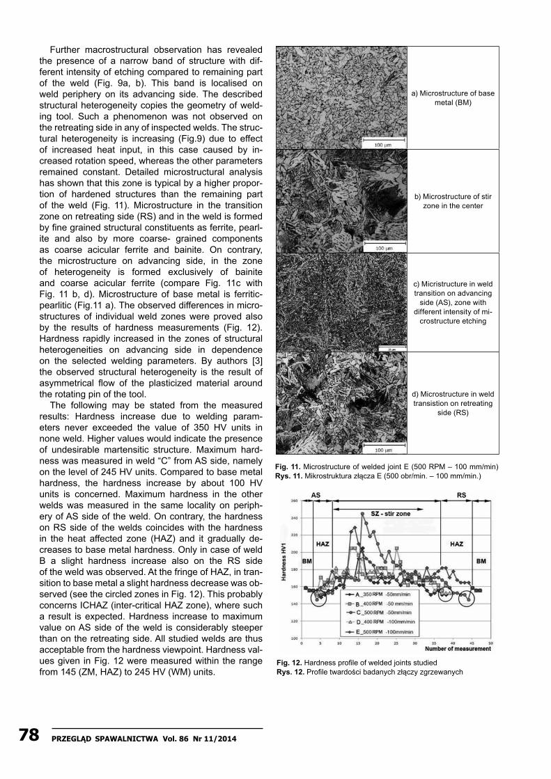
Further macrostructural observation has revealed the presence of a narrow band of structure with dif-ferent intensity of etching compared to remaining part of the weld (Fig. 9a, b). This band is localised on weld periphery on its advancing side. The described structural heterogeneity copies the geometry of weld-ing tool. Such a phenomenon was not observed on the retreating side in any of inspected welds. The struc-tural heterogeneity is increasing (Fig.9) due to effect of increased heat input, in this case caused by in-creased rotation speed, whereas the other parameters remained constant. Detailed microstructural analysis has shown that this zone is typical by a higher propor-tion of hardened structures than the remaining part of the weld (Fig. 11). Microstructure in the transition zone on retreating side (RS) and in the weld is formed by fine grained structural constituents as ferrite, pearl-ite and also by more coarse- grained components as coarse acicular ferrite and bainite. On contrary, the microstructure on advancing side, in the zone of heterogeneity is formed exclusively of bainite and coarse acicular ferrite (compare Fig. 11c with Fig. 11 b, d). Microstructure of base metal is ferritic- pearlitic (Fig.11 a). The observed differences in micro-structures of individual weld zones were proved also by the results of hardness measurements (Fig. 12). Hardness rapidly increased in the zones of structural heterogeneities on advancing side in dependence on the selected welding parameters. By authors [3] the observed structural heterogeneity is the result of asymmetrical flow of the plasticized material around the rotating pin of the tool.
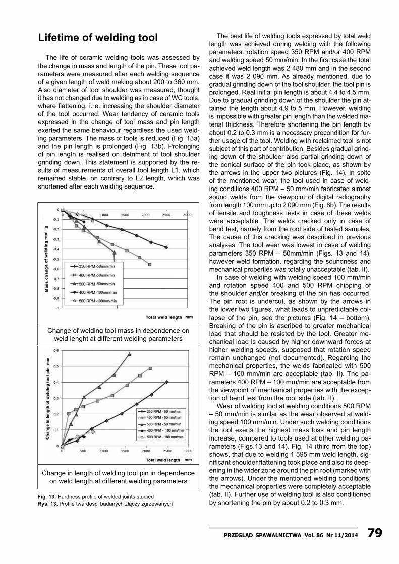
The following may be stated from the measured results: Hardness increase due to welding param-eters never exceeded the value of 350 HV units in none weld. Higher values would indicate the presence of undesirable martensitic structure. Maximum hard-ness was measured in weld “C” from AS side, namely on the level of 245 HV units. Compared to base metal hardness, the hardness increase by about 100 HV units is concerned. Maximum hardness in the other welds was measured in the same locality on periph-ery of AS side of the weld. On contrary, the hardness on RS side of the welds coincides with the hardness in the heat affected zone (HAZ) and it gradually de-creases to base metal hardness. Only in case of weld B a slight hardness increase also on the RS side of the weld was observed. At the fringe of HAZ, in tran-sition to base metal a slight hardness decrease was ob-served (see the circled zones in Fig. 12). This probably concerns ICHAZ (inter-critical HAZ zone), where such a result is expected. Hardness increase to maximum value on AS side of the weld is considerably steeper than on the retreating side. All studied welds are thus acceptable from the hardness viewpoint. Hardness val-ues given in Fig. 12 were measured within the range from 145 (ZM, HAZ) to 245 HV (wM) units.
a) Microstructure of base metal (BM)
b) Microstructure of stir zone in the center
c) Micristructure in weld transition on advancing
side (AS), zone with different intensity of mi-
crostructure etching
d) Microstructure in weld transistion on retreating
side (RS)
Fig. 11. Microstructure of welded joint E (500 RPM – 100 mm/min) Rys. 11. Mikrostruktura złącza E (500 obr/min. – 100 mm/min.)
Fig. 12. Hardness profile of welded joints studied Rys. 12. Profile twardości badanych złączy zgrzewanych
79Przegląd sPawalnictwa Vol. 86 nr 11/2014
Lifetime of welding tool
The life of ceramic welding tools was assessed by the change in mass and length of the pin. These tool pa-rameters were measured after each welding sequence of a given length of weld making about 200 to 360 mm. Also diameter of tool shoulder was measured, thought it has not changed due to welding as in case of wC tools, where flattening, i. e. increasing the shoulder diameter of the tool occurred. wear tendency of ceramic tools expressed in the change of tool mass and pin length exerted the same behaviour regardless the used weld-ing parameters. The mass of tools is reduced (Fig. 13a) and the pin length is prolonged (Fig. 13b). Prolonging of pin length is realised on detriment of tool shoulder grinding down. This statement is supported by the re-sults of measurements of overall tool length L1, which remained stable, on contrary to L2 length, which was shortened after each welding sequence.
Fig. 13. Hardness profile of welded joints studied Rys. 13. Profile twardości badanych złączy zgrzewanych
Change of welding tool mass in dependence on weld lenght at different welding parameters
Change in length of welding tool pin in dependence on weld length at different welding parameters
The best life of welding tools expressed by total weld length was achieved during welding with the following parameters: rotation speed 350 RPM and/or 400 RPM and welding speed 50 mm/min. In the first case the total achieved weld length was 2 480 mm and in the second case it was 2 090 mm. As already mentioned, due to gradual grinding down of the tool shoulder, the tool pin is prolonged. Real initial pin length is about 4.4 to 4.5 mm. Due to gradual grinding down of the shoulder the pin at-tained the length about 4.9 to 5 mm. However, welding is impossible with greater pin length than the welded ma-terial thickness. Therefore shortening the pin length by about 0.2 to 0.3 mm is a necessary precondition for fur-ther usage of the tool. welding with reclaimed tool is not subject of this part of contribution. Besides gradual grind-ing down of the shoulder also partial grinding down of the conical surface of the pin took place, as shown by the arrows in the upper two pictures (Fig. 14). In spite of the mentioned wear, the tool used in case of weld-ing conditions 400 RPM – 50 mm/min fabricated almost sound welds from the viewpoint of digital radiography from length 100 mm up to 2 090 mm (Fig. 8b). The results of tensile and toughness tests in case of these welds were acceptable. The welds cracked only in case of bend test, namely from the root side of tested samples. The cause of this cracking was described in previous analyses. The tool wear was lowest in case of welding parameters 350 RPM – 50mm/min (Figs. 13 and 14), however weld formation, regarding the soundness and mechanical properties was totally unacceptable (tab. II).
In case of welding with welding speed 100 mm/min and rotation speed 400 and 500 RPM chipping of the shoulder and/or breaking of the pin has occurred. The pin root is undercut, as shown by the arrows in the lower two figures, what leads to unpredictable col-lapse of the pin, see the pictures (Fig. 14 – bottom). Breaking of the pin is ascribed to greater mechanical load that should be resisted by the tool. Greater me-chanical load is caused by higher downward forces at higher welding speeds, supposed that rotation speed remain unchanged (not documented). Regarding the mechanical properties, the welds fabricated with 500 RPM – 100 mm/min are acceptable (tab. II). The pa-rameters 400 RPM – 100 mm/min are acceptable from the viewpoint of mechanical properties with the excep-tion of bend test from the root side (tab. II).
wear of welding tool at welding conditions 500 RPM – 50 mm/min is similar as the wear observed at weld-ing speed 100 mm/min. Under such welding conditions the tool exerts the highest mass loss and pin length increase, compared to tools used at other welding pa-rameters (Figs.13 and 14). Fig. 14 (third from the top) shows, that due to welding 1 595 mm weld length, sig-nificant shoulder flattening took place and also its deep-ening in the wider zone around the pin root (marked with the arrows). Under the mentioned welding conditions, the mechanical properties were completely acceptable (tab. II). Further use of welding tool is also conditioned by shortening the pin by about 0.2 to 0.3 mm.

80 Przegląd sPawalnictwa Vol. 86 nr 11/2014
Geometry of ceramic welding tools
Before welding after welding
Fig. 14. wear character of Si3n4 welding tools in dependence on weld length at different welding parameters Rys. 14. Przykład zużycia narzędzia z Si3n4 w zależności od długości złącza i innych parametrów zgrzewania
DiscussionIn case of welding with wC (tungsten carbide) tools,
it was found out that they are not suitable for welding thicknesses 5 mm and more. The welding tools are geometrically unstable. Flattening the tool shoulder together with the pin takes place. The pin attains bar-rel- like shape. Owing to tool shoulder flattening its di-ameter increases by 1 to 1.5 mm. Such significant tool shape instability is connected with problems to achieve acceptable weld integrity. The tool life is max 500 mm of weld length.
In case of welding with ceramic tools the life ex-pressed in weld length is at least 4-times higher, i.e. about 2 000 mm. Precondition for further use of the tool after welding the mentioned weld length necessitates its reclaiming. Reclaiming consists in shortening the pin, eventually in renovation of concave shape of the tool shoulder. The length of pin is pro-longed by shoulder grinding down. The tool shoulder
diameter remains the same. It does not change than in case of wC tools. On the other hand the ceramic tools are susceptible to destruction in case of interac-tion of the face edge of the tool with material welded.
In spite of dimensional stability of ceramic tool, two types of defects were observed, depending on the pa-rameters used:1. Longitudinal voids – localised on AS side of the weld,
as the consequence of insufficient stirring of materi-als welded.
2. Longitudinal cracks – localised in the weld root pe-riphery on its advancing side. Location of crack oc-currence corresponds with the tool shape, namely the zone of sharp tool edge between the conical and face surface of the pin. These defects show the character of sharp cracks, initiated due to viscous (thermal) gra-dients in the subsurface layer of the weld root.To eliminate the first type of defects increase in
heat input is recommended, in our case by increasing the spindle revolutions. To eliminate the second type

81Przegląd sPawalnictwa Vol. 86 nr 11/2014
of defects we suggest to optimize the welding process by the geometrical change of welding tool, namely due to the following reason:
The occurring crack has formed on the weld root pe-riphery in the solid and sound material, i.e. in the zone where an intense stirring was not necessary in order to form a metallurgical bond, as requested in the zone of butt welding line of the weld.
The change in tool geometry should be aimed at re-ducing the intensity of stirring of materials welded on the root periphery. The simplest way how to achieve this requirement is to chamfer and/or to round the edge on the pin tip. By reducing the tool surface area, the thermal-strain effect of the tool will be suppressed. Moreover come out from the basic principles of design,
the sharp edges are always the highest stress concen-trators. we were conscious of this fact during tool de-sign suggestion.
The used geometry was selected regarding the re-quirement of the lowest possible price, since the high-est costs are connected with intricate machining of the hard materials in combination with relatively short life of the tool. This means that machining of other surfaces, chamfers and radii on the tools are imposing the addi-tional costs. Short life and high price for tool manufac-ture are the main retarders for application of FSw tech-nology for welding steel products in technical practice, but on the other hand they are also the driving force for development in the field of tool geometry and material for the welding tool.
References[1] Rai, R. et al.: Review: friction stir welding tools, Science and
Technology of welding and Joining, volume 16, no. 4, 2011.[2] Thomas, w. M. – Threadgill, P. L. – nicholas, E. D.: Feasibility
of friction stir welding steel, Science na technology of welding and joining, Vol. 4, no. 6, 1999, s. 1362-1718.
[3] nandan, R., et al.: Recent advances in friction-stir welding – Process weldment structure and properties, Progress in Materials Science 53, 2008, s. 980-1023.
[4] nelson, T. w.: Friction stir welding of ferrous alloys: current status, Material Science Forum, 2010, s. 638-642.
[5] Prado, R. A. a kol.: Self-optimization in tool wear for friction-stir welding of Al 6061 + 20% Al2O3 MMC, Materials Science and Engineering A349, 2003, s. 156-165.
[6] Fernandez, G. J. a kol.: Characterization of tool wear and weld optimization in the friction-stir welding of cast alumi-num 359+20% SiC metal-matrix composite.
[7] Kumar, K. et al.: The role of friction stir welding tool on mate-rial flow and weld formation, Materials Science and Engineer-ing A485, 2008, s. 367-374.
[8] Hua-Bin Chen et al.: The investigation of typical welding de-fects for 5456 aluminum alloy friction stir welds, Materials Sci-ence and Engineering A433, 2006, s. 64-69.
ConclusionsThe aim of this work was to demonstrate welding
of ferritic steel type S235JRC+n, 5 mm in thickness by use of friction stir welding (FSw) technology. The effect of selected weldingparameters was studied, as tool material (tungsten carbide – wC, and/or silicon nitride – Si3n4), welding speed, rota-tion speed on the properties of welded joints and life-time of welding tools. Based on the achieved results, we have assessed the studied welding parameters and conditions as follows:
1) Material and welding tool geometry: wC welding steels are not suitable for welding steel with thickness of 5 mm and more. The greatest life of tool, about 2,1 m of weld length was achieved with the ceramic Si3n4 tool at parameters 400 RPM – 50 mm/min, whereas relatively sound weld was thus attained. After fabrica-tion of the mentioned weld length it is necessary to reclaim the tool, at least by shortening the pin length. Regarding the tool geometry it is recommended to round the tip of the conical pin with the aim to elimi-nate the crack occurrence in weld root periphery.
2) Rotation speed: with increasing rotation speed also the wear rate of welding tools is increasing. The welds fabricated with rotation speed 500 RPM have exerted a more stable integrity and also bet-ter mechanical properties than those fabricated with rotation speed 400 RPM. In case of welding with rotation speed 350 RPM unacceptable integ-rity of fabricated welds was observed. Owing to increased rotation speed (heat input) formation of structural heterogeneity in the weld occurs, which is spread in a narrow band on AS side and it is typi-cal with presence of harder structures when com-pared with the structures of the remaining part of the weld.
3) welding speed: due to increasing welding speed also the risk of damage of ceramic weld-ing tools is increased. On contrary, in case of wC tools, increased welding speed is less wearing and destabilizing the geometry of welding tool. However, at welding speeds higher than 100 mm/min within the tested rotation speed the risk of formation of lon-gitudinal voids is increasing as a consequence of in-sufficient stirring of materials welded.
This publication is the result of the project implementation: Research of friction stir welding (FSW) application as an alternative to mel-ting welding methods, ITMS: 26240220031, supported by the Research & Development Operational Programme funded by the ERDF.