the effect of polymer melt rheology on predicted die...
TRANSCRIPT

THE EFFECT OF POLYMER MELT RHEOLOGY ON PREDICTED DIE SWELL AND FIBER ORIENTATION IN FUSED FILAMENT FABRICATION NOZZLE FLOW
Z. Wang and D.E. Smith
Department of Mechanical Engineering, Baylor University, Waco, TX 76798
Abstract
Short carbon fibers suspended in the polymer feedstock enhances the mechanical performance of products produced with Fused Filament Fabrication (FFF). As the melted filament is extruded and deposited on a moving platform, the velocity gradients within the polymer melt flow orientate the fibers, and the final orientation has a direct effect on the mechanical properties of printed bead. This paper numerically simulates an FFF nozzle flow, including the extrudate material beyond the nozzle exit. Finite element simulations of the extrusion process are performed with Generalized Newtonian Fluid (GNF) models and a viscoelastic rheology model, included in ANSYS Polyflow, to evaluate the polymer melt velocity field and predict die swell. Fiber orientation tensors are computed along streamlines using the Fast Exact Closure and Folgar-Tucker isotropic rotary diffusion. The predictions indicate that shear thinning behavior reduces the die swell but viscoelastic rheology significantly intensifies the extrudate swell. Orientation tensor values calculated from the flow results of the viscoelastic model yields lower principal alignment in printed beads than those computed with GNF models.
Introduction
Fused Filament Fabrication (FFF), which is also known as Fused Deposition Modelling (FDM), is a widely used Additive Manufacturing (AM) technique due to its rapid manufacturing speed and low-cost. The FFF process is an extrusion-based process where polymer feedstock materials are melted and deposited on a heated platform layer-by-layer to form three-dimensional (3D) objects [1]. Recently, Oak Ridge National Laboratory (ORNL) and their associated collaborators have extended the FFF process from small scale rapid prototyping to large scale manufacturing for parts and tooling [2]. To achieve relatively high dimensional accuracy and superior mechanical performance, carbon fiber filled polymers are employed the large scale FFF system. Studies have shown that adding short carbon fibers into the neat polymer yields a composite with improved material performance [3]. The prediction of fiber alignment within the printed bead is pivotal in the FFF extrusion process since fiber orientation greatly influences the material properties of solidified parts [3]. Evans, et al. [4] and Libscomb, et al. [5] showed that a rigorous simulation of the fiber suspension flow problem should include the effect of the flow on the fiber orientation as well as the fiber orientation influence on the flow rheology, in which the “fully-coupled” calculations require considerable computational expenses. To save computational time, these models are typically decoupled, such as in injection and compression modelling simulations, by using the flow kinematics to predict the fiber orientation. The decoupled formulation has been shown (c.f.
1082
Solid Freeform Fabrication 2017: Proceedings of the 28th Annual International Solid Freeform Fabrication Symposium – An Additive Manufacturing Conference

Tucker et al. [6]) to work well in shear dominated flows such as those that occur in injection molding [7] and compression molding [8]. Fiber orientation investigations involved in Additive Manufacturing applications are still quite limited. Nixon, et al. [9] numerically evaluated the fiber orientation conditions for three FDM nozzle geometries (convergent, straight and divergent) using the Moldflow (Moldflow Corporation, Framingham, MA) and the Folgar-Tucker diffusion model. The computed results showed that the convergent geometry achieved the highest fiber alignment and the divergent geometry resulted in the lowest. Additionally, at the exit of the straight nozzle as well as the convergent nozzle, a higher alignment is found around the core area than the boundary area which was not seen in the experimental result reported by Kunc [10]. Heller, et al. [11] predicted the fiber orientation tensor of a conventional FDM nozzle and the extruded filament where die swell was evaluated numerically in the solution process. The COMSOL Multiphysics (Comsol, Inc., Burlington, MA) software was used to calculate the velocity and the velocity gradient field of the flow domain assuming the polymer behaved as an isothermal Newtonian fluid in a creeping flow. Orientation tensors (see, e.g. Advani and Tucker [12]) were used to evaluate fiber orientation along streamlines within the flow domain from velocity and velocity gradient information. Their results show that fiber alignment reached its peak at the boundary of the nozzle and decayed towards to the center. Also, an extrudate swell ratio (c.f. Equation 7 below) of 13% was computed which is near the established accepted values for Newtonian fluids. Extrudate swell occurs in many extrusion-based polymer processes such as that observed for the Strangpresse (Strangpresse, Inc, Youngstown, OH) AM extruder appearing in Figure 2-a. Based on earlier results, it is expected that the sudden change of the flow boundary at the nozzle exit will result a notable variation in fiber orientation downstream. Molten polymers are well known to exhibit a non-Newtonian behavior which has been modeled successfully with viscoelastic fluid models that exhibit both viscous and elastic effects. The flow of a viscoelastic fluid is influenced by the first normal stress difference, which is considered to be a main contributor to die swell [13]. Keunings [14] and Huang, et al. [15] reviewed the preceding literature associated with the discussion of die swell. Luo and Tanner [16] exploited the Streamline Finite Element Method (SFEM) on solving the die swell problem. Luo and Mitsoulis [17] refined the SFEM by introducing a particle-tracking scheme along the streamlines and iterate the algorithm by Picard scheme. Beraudo, et al. [18] introduced a finite-element-based method to investigate the extrudate swell of LLDPE and LDPE melts using the Phan-Thien-Tanner (PTT) Model [22], a differential-type viscoelastic fluid model, based on geometries of a 2D slit die and a 2D axisymmetric capillary die. Their results shown a good agreement with related experimental data but over-estimated the swell in high shear condition. Ganvir, et al. [21] proposed an Arbitrary Lagrangian Eulerian (ALE) algorithm for solving the die swell problem for both the steady state and transient problems. Their formulation behaved well at high shear rate but was unstable under low shear. This paper presents a numerical approach to evaluate fiber orientation in a large scale FFF extruder nozzle and the post-nozzle extrudate, including a prediction of the die swell at the nozzle exit. Our numerical model is created through the finite element suite ANSYS Polyflow (ANSYS, Inc., Canonsburg, PA). When modeling the flow, three Generalized Newtonian Fluid (GNF) models and a viscoelastic fluid model are employed in separate simulations. A decoupled
1083

formation is used to compute the fiber orientation within the polymer melt flow. The Advani-Tucker fiber orientation tensor [12] and the Isotropic Rotary Diffusion Model [19] are employed in the computation of the fiber orientation along streamlines within the flow domain. The Fast Exact Closure of Montgomery-Smith, et al. [20] is applied to address the closure problem in the fiber orientation simulations.
Nozzle Flow Modelling
The simulations involved in this research are based on the large scale additive manufacturing Strangpresse Model-19 extruder appearing in Figure 1. Figure 1-a shows the extrusion of neat ABS polymer from the nozzle and important geometrical dimensions of the Strangpresse Model 19 large scale AM extruder nozzle appear in the Figure 1-b. Our extruder nozzle flow model is based on this design, and also includes a 20-mm strand of polymer extrudate beyond the nozzle exit to simulate the effect of die swell. Due to the axisymmetry of the nozzle geometry and assumed flow, we consider only half of the flow domain using a 2-D axisymmetric model to reduce computational expense. Note that the axisymmetric assumption ignores any swirling motion of the flow that may result from the extruder screw, which is a topic of future research.
The boundary conditions of the flow domain are shown in Figure 2-a, in which Q is the volumetric flow rate, F is the tangential force, F is the normal force, v is the tangential velocity, v is the normal velocity, is the velocity vector at the free surface, and is normal vector to the free surface [13]. The finite element domain is discretized into 20,382 nodes and 19,866 elements using the 4-node quadrilateral element. The mesh in the convergence zone and the nozzle exit is shown in Figure 2-b. Additionally, the polymer melt flow is under the isothermal assumption for simplicity.
(a) (b)
Figure 1. (a) Neat ABS exhibit obvious die swell as is extruded throught the Model-19 extruder nozzle. (b) Essentail geometric dimensions of the nozzle.
1084

(a) (b)
Figure 2. (a) Essentail boundary conditions of the flow domain (b) Mesh of convergent zone as well as the nozzle exit.
Material Rheology
Ganvir, et al. [21] simulated die swell of the LDPE and LLDPE in a capillary die using the Phan-Thien-Tanner (PTT) rheology model [22] for the molten polymer. The numerical prediction gave a good agreement with previous experimental and numerical results [21]. The PTT model is assumed to be one of the most realistic rheology model in the family of the Differential Viscoelastic Fluid (DVF) models [13]. A comparable study using ABS has yet to be performed, so we have chosen to use LLDPE properties from Ganvir, et al. [21] in this study to validate our PTT flow modeling approach given that data exist in the literature for this comparison. However, we do realize that LLDPE is not common in AM, and our future work will focus on ABS and other AM materials as we develop a database of the required viscoelastic material properties. The shear viscosity of a polymer melt is well known to be shear rate dependent and commonly exhibit shear thinning behavior. This is particularly true for LLDPE [21]. To capture the shear thinning phenomenon in our nozzle flow model, we first consider various Generalized Newtonian Fluid (GNF) models. The Power law model is given as [23] η γ K λγ (Equation 1)
1085
where K is the consistency factor, λ is the natural time, and n is the power-law index. The Bird-Carreau law captures the shear thinning behavior of the Power law form, and also includes a Newtonian plateau at low shear rates. It is given as [23] η γ η η η 1 λ γ
(Equation 2)
where η is the infinite-shear-rate viscosity, η is the zero-shear-rate viscosity, λ is the natural time, and n is the power-law index. We also consider the Cross law GNF model written as [23] η γ
η1 λγ
(Equation 3)
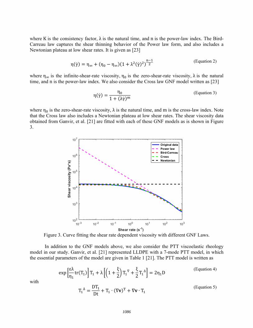
where η is the zero-shear-rate viscosity, λ is the natural time, and m is the cross-law index. Note that the Cross law also includes a Newtonian plateau at low shear rates. The shear viscosity data obtained from Ganvir, et al. [21] are fitted with each of these GNF models as is shown in Figure 3.
Figure 3. Curve fitting the shear rate dependent viscosity with different GNF Laws.
In addition to the GNF models above, we also consider the PTT viscoelastic rheology model in our study. Ganvir, et al. [21] represented LLDPE with a 7-mode PTT model, in which the essential parameters of the model are given in Table 1 [21]. The PTT model is written as
expεληtr T T λ 1
ξ2T
ξ2T ∆ 2η D
(Equation 4)
with
T ∆ DTDt
T ∙ ∙ T (Equation 5)
1086

and
TDTDt
T ∙ ∙ T (Equation 6)
where T and η are the total stress tensor and the total viscosity, respectively. The tensor D
is the strain rate tensor, where is the velocity vector, is the mode relaxation
time, is the mode viscosity, controls the shear viscosity behavior and controls the elongational behavior. Moreover, we plot the storage shear modulus, loss shear modulus and the steady state shear viscosity in Figure 4 based on the parameters given in Table 1. As is seen, the PTT model also presents the shear thinning behavior that is given in the GNF models above. From Equations 2 to 6, it can be seen that the Power Law, Bird-Carreau law, Cross law as well as the PTT model include inherent non-linearity in their constitutive equations. We expect that polymer melt flow results using GNF and PTT rheology models may vary considerably from those obtained when assuming a Newtonian fluid model. Furthermore, simulations using non-Newtonian models are nonlinear which would yield flow-rate dependent results. In the study below, we use a volumetric flow rate Q =10 / with the fully developed velocity profile inlet condition imposed as is shown in Figure 5. Other flow rates are expected to yield different fiber orientation results when using non-Newtonian fluid models.
Table 1. Parameters of the 7-mode PTT model of the LLDPE [21]
∙ 1 1.28E-4 2.367E+2 0.35 0.06 2 6.12E-3 1.346E+3 0.35 0.06 3 4.10E-2 3.363E+3 0.35 0.06 4 2.77E-1 4.691E+3 0.35 0.06 5 2.01E-0 3.726E+3 0.35 0.06 6 1.57E+1 2.007E+3 0.35 0.06 7 1.35E+2 9.563E+2 0.35 0.06
1087

Figure 4. Rheological properties of the LLDPE obtained by the PTT parameters given in Ganvir, et al. [21].
Figure 5. Examples of fully developed velocity profiles imposed at the inlet of the nozzle domain with Q = 10 /s.
Extrudate Swell Prediction using GNF Models
We first consider the flow of polymer melt flow through the large scale FFF nozzle using the GNF rheology models given above. The parameter swell ratio ( ) is used to assess the amount of die swell predicted in the polymer extrudate for each fluid rheology model. The swell ratio used here is the ratio of the steady state swell flow diameter ( ) to the nozzle exit diameter ( ), written as [13]
1088

100% (Equation 7)
Heller, et al. [11] calculated a 13% die swell when modeling a Newtonian Fluid exiting a small scale FFF nozzle. Our Newtonian fluid die swell results that appear in Figure 7 yield a similar value as shown. Die swell predictions using the GNF model given above generally yield lower die swell ratios as compared with Newtonian Fluid results. In detail, the Power Law [23] gives a 1.8% swell ratio, Bird-Carreau Law and Cross Law [23] give similar results, which are about 8.8%. Specifically, the die swell predicted by the Cross law is 30.5% less than using the Newtonian model.
Extrudate Swell Prediction using PTT Model
Melt flow simulations were also performed for the large scale FFF nozzle flow using the PTT viscoelastic fluid model. The ANSYS-Polyflow PTT model was employed using the LLDPE parameters appearing in Table 1 above. Before simulating the FFF nozzle with the PTT fluid, we first considered the 2D axisymmetric capillary flow domain shown in Figure 6-a taken from Ganvir, et al. [21] to validate our PTT flow simulation process. Note that the lower 14.2 mm of the model is used to capture the die swell. In this model, the die length to diameter ratio ( / ) is 19.2 and the volumetric flow rate is about 10 / . It can be seen that the predicted free surface shown in Figure 6-b has a good agreement with the published literature. Once our modeling approach was validated with literature data above, we applied the PTT rheology model to the FFF nozzle flow domain shown in Figure 2-a to obtain the velocity field within the melt flow and the predicted die swell. From the comparison shown in Figure 7. Computed results show that the PTT model yields a higher die swell than the GNF models due to the elastic effect that is included in the PTT model. Moreover, the swell profile of the PTT model does not reach the steady state within the first 20 mm of the free extrudate while the results of Newtonian Fluid model and GNF models reach steady state at roughly the first 2 mm. Note, the PTT model’s 22.4% swell ratio is computed based on the swelled diameter at the 20 mm position. In particular, the PTT model’s predicted result is 72.2% higher than that of the Newtonian Fluid model, and the increase between results of the PTT model and the Cross law is even over 160%. The above analysis indicates that the elastic effects of the viscoelastic fluid flow significantly enhance the extrudate swell phenomenon even with considering the decreasing effect of the shear thinning behavior.
1089

(a) (b) Figures 6. (a) Representation of the capillary die used in the validation study (b) Extrudate swell predictions for the die flow domain.
Figure 7. Extrudate swell predictions of the PTT model, NF model, and GNF models.
Fiber Orientation Prediction using Decoupled Model
The flow-induced fiber orientation pattern is determined using the decoupled fiber orientation tensor formulation [11]. The Advani-Tucker [12] fiber orientation tensors are used with the Fast Exact Closure [20] and the Folgar-Tucker isotropic rotary diffusion [19] as
1090

∙ ∙ ∙ ∙ 2 : 2 3
(Equation 8)
where A is the 2nd order orientation tensor in three dimensional space with components given as
= (Equation 9)
In the above, the vorticity tensor W is written in terms of the velocity vector v as = (Equation 10)
and, similarly, the rate of deformation tensor D is D = (Equation 11)
In our simulations, the velocity vector is computed along streamlines that occur in the polymer melt flow field obtained from our ANSYS Polyflow model. In addition, is a constant that depends on the fiber aspect ratio, is the interaction coefficient that models the effect of fiber-fiber interaction on the orientation distribution. The scalar magnitude of the rate of deformation tensor D is and is the 4th order fiber orientation tensor, which is typically solved by a closure approximation [3]. In this study, Fast Exact Closure [20] is used to solve for
. It is important to note that the orientation tensor approach does not track each individual fiber, but instead provides an indication of the degree of orientation through the components of A appearing in Equation 9. As shown in Figure 8, values of a diagonal component of A having a value of one represents full alignment in a given direction (shown as in Figure 8-a), and values of 1/3 on all diagonal components represent the case of a uniformly random orientations (cf. Figure 8-b). Recall, in Figure 2, we define the extrusion direction of the melt is along direction, thus, the component is of particular importance since it indicates how well the fibers align along the principal extrusion direction. The fiber orientation tensor solution of A22 shown in Figure 10 is based on the flow kinematics solved using the PTT rheology model, in which the streamlines numbers in the legend corresponds to the highlighted streamlines in Figure 9. In our solution, we assume the initial fiber orientation state at the nozzle entrance is uniformly random, and we note that other initial conditions on A (at the inlet) may result in different fiber orientation variation within the nozzle geometry. In addition, we assume = 0.9802 and = 0.0075, as in Heller, et al. [11]. A relative comparison is given in Figure 11, in which the steady state values of the component solved by flow kinematics using the Newtonian fluid model, GNF models and the PTT model. Among the comparison, it shown that the PTT model kinematics yields lowest steady state principal fiber orientation alignment, on average. The variation of the principal fiber orientation alignment decrease initially and recovers gradually as moving from the boundary toward to the center of the nozzle. Furthermore, we compute the absolute relative difference (∆,
1091

cf. Equation 12) between the PTT model results and each of the other set of data using the equation as below, ∆ | / | 100% (Equation 12) Results show that the Newtonian fluid model, the Power law, the Bird-Carreau law and the Cross law have 7%, 26.1%, 13.1% and 12.6% difference from the PTT’s result, respectively.
(a) (b) Figure 8. Fiber orientation tensor of (a) Full alignment along direction (b) Uniformly random alignment.
Figure 9. Representation of the streamlines in the nozzle flow domain
1092

Figure 10. component of fiber orientation solution computed using the flow kinematics solved by the PTT model.
Figure 11. Comparison between the steady state component solved by different flow kinematic results.
1093

Conclusion
A few conclusions have been reached based on the simulations presented in this paper. The shear thinning behavior of polymer melts reduces die swell effect. In particular, in the case of LLDPE [21], the reduction of the swell ratio is 30.5% comparing GNF Cross law to the Newtonian fluid model. The viscoelastic rheology of polymer melts greatly enhances the die swell. Again, by using LLDPE [21], we found an increase of 72.2% in terms of the swelled ratio, comparing the PTT model results to the Newtonian fluid results. Based on the fiber orientation prediction of the decoupled model, it is observed that the highest principal alignment state occurs at the streamline closest to the boundary, and shows a concave down variation trend as moving from boundary to the center line. Furthermore, the PTT model yields lower principal alignment results than those from GNF models. In detail, the prediction of the PTT model is 7% lower comparing to Newtonian model’s; 13% lower comparing to Bird-Carreau’s or Cross law’s; and 26% lower comparing to the Power law, on average.
Future Work
Future work will include simulations with materials and flow rates that are typical of
large scale polymer deposition additive manufacturing. This includes ABS and carbon fiber filled ABS materials, and flow rates in the 10 to 15 lbs per hour range. We also plan to develop a simulation method that employs the ANSYS Polyflow simplified viscoelastic rheology model to reduce computation time. Finally, a couple fiber orientation and flow velocity analysis is needed to more accurately account for influence of the suspended fibers on melt viscosity.
Acknowledgements
The authors would like to thank the Oak Ridge National Lab (RAMP-UP 40001455134)
as well as Baylor University for funding this research project. Also, we would like to thank the Strangpresse corporation for donating their Model-19 extruder to our study.
References [1] Brenken, B., Favaloro, A. Barocio, E. Denardo, N. Kunc, V., Pipes, R.B., Fused Deposition Modeling of Fiber-Reinforced Thermoplastic Polymers: Past Progress and Future Needs. In Proceedings of the American Society for Composites: Thirty-First Technical Conference 2016. [2] Love L.J., Utility of big area additive manufacturing (BAAM) for the rapid manufacture of customized electric vehicles. Oak Ridge National Laboratory (ORNL); Manufacturing Demonstration Facility (MDF); 2015 Aug 1. [3] Verweyst B.E., Tucker C.L., Fiber suspensions in complex geometries: flow/orientation coupling. The Canadian Journal of Chemical Engineering. 2002 Dec 1;80(6):1093-106. [4] Evans J.G., The effect of non-Newtonian properties of a suspension of rod-like particles on flow fields. Theoretical Rheology, Halstead Press, New York. 1975:224-32. [5] Lipscomb, G.G., Denn, M.M., Hur, D.U., Boger, D.V., The flow of fiber suspensions in complex geometries. Journal of Non-Newtonian Fluid Mechanics. 1988 Jan 1;26(3):297-325. [6] Tucker C.L., Flow regimes for fiber suspensions in narrow gaps. Journal of Non-Newtonian fluid mechanics. 1991 Jan 1;39(3):239-68.
1094

[7] Bay, Randy S., Tucker, C.L., "Fiber orientation in simple injection moldings. Part I: Theory and numerical methods." Polymer composites 13.4 (1992): 317-331. [8] Jackson W.C., Advani S.G., Tucker C.L., Predicting the orientation of short fibers in thin compression moldings. Journal of Composite Materials. 1986 Nov;20(6):539-57. [10] Kunc, V., Advances and Challenges in Large Scale Polymer Additive Manufacturing. In15th SPE Automotive Composites Conference, Novi, MI 2015 Sep 9. [11] Heller, B., Smith, D.E., Jack, D.A., The Effects of Extrudate Swell, Nozzle Shape, and the Nozzle Convergence Zone on Fiber Orientation in Fused Deposition Modeling Nozzle Flow. InAmerican Society of Composites-30th Technical Conference 2015 Nov 2. [12] Advani S.G., Tucker, C.L., The use of tensors to describe and predict fiber orientation in short fiber composites. Journal of rheology. 1987 Nov;31(8):751-84. [13] ANSYS POLYFLOW User's Guide, Ansys Inc., 2013. [14] Barone M.R., Castro, J.M., Ellson, R.N., Giiçeri, S.I., Kamal, M.R., Keunings, R., Lee, C.C., Lee, H.S., Lu, S.C., Osswald, T.A., Pittman, J.F., Fundamentals of computer modeling for polymer processing. Hanser; 1989. [15] Huang, S.X., Lu, C.J., Stress relaxation characteristics and extrudate swell of the IUPAC-LDPE melt. Journal of non-newtonian fluid mechanics. 2006 Jul 15;136(2):147-56.. [16] Luo, X.L., Tanner, R.I., A streamline element scheme for solving viscoelastic flowproblems part II: integral constitutive models. Journal of Non-Newtonian Fluid Mechanics. 1986 Jan 1;22(1):61-89. [17] Luo, X.L., Mitsoulis, E., An efficient algorithm for strain history tracking in finite element computations of non�Newtonian fluids with integral constitutive equations. International Journal for Numerical Methods in Fluids. 1990 Nov 1;11(7):1015-31. [18] Béraudo, C., Fortin, A., Coupez, T., Demay, Y., Vergnes, B., Agassant, J.F., A finite element method for computing the flow of multi-mode viscoelastic fluids: comparison with experiments. Journal of non-newtonian fluid mechanics. 1998 Feb 28;75(1):1-23. [19] Phelps, J.H., Tucker, C.L., An anisotropic rotary diffusion model for fiber orientation in short-and long-fiber thermoplastics. Journal of Non-Newtonian Fluid Mechanics. 2009 Feb 28;156(3):165-76. [20] Montgomery-Smith, S., Jack, D., Smith, D.E., The fast exact closure for Jeffery’s equation with diffusion. Journal of Non-Newtonian Fluid Mechanics. 2011 Apr 30;166(7):343-53. [21] Ganvir, V., Lele, A., Thaokar, R., Gautham, B.P., Prediction of extrudate swell in polymer melt extrusion using an Arbitrary Lagrangian Eulerian (ALE) based finite element method. Journal of Non-Newtonian Fluid Mechanics. 2009 Jan 31;156(1):21-8. [22] Thien, N.P., Tanner, R.I., A new constitutive equation derived from network theory. Journal of Non-Newtonian Fluid Mechanics. 1977 Jul 1;2(4):353-65. [23] Tadmor, Z., Gogos, C.G., Principles of polymer processing. John Wiley & Sons; 2006.
1095