the effect of infill wall on seismic performance of...
TRANSCRIPT

COMPDYN 2011 III ECCOMAS Thematic Conference on
Computational Methods in Structural Dynamics and Earthquake Engineering M. Papadrakakis, M. Fragiadakis, V. Plevris (eds.)
Corfu, Greece, 25–28 May 2011
THE EFFECT OF INFILL WALL ON SEISMIC PERFORMANCE OF DEFICIENT RC STRUCTURES
U. Akpınar1, R. Ozcelik2, B. Binici3
1 Middle East Technical University Middle East Technical University, Department of Civil Engineering, Turkey
2 Middle East Technical University Middle East Technical University, Department of Civil Engineering, Turkey
3 Middle East Technical University Middle East Technical University, Department of Civil Engineering, Turkey
Keywords: Infill Walls, RC Frames, Nonlinear Time History Analyses.
Abstract. This study investigates the possible adverse effects of the infill walls on the seismic response of the deficient reinforced concrete structures. It is shown herein that neglecting the presence of infill walls may not always a safe design approach. First the modeling approach is verified against available pseudo dynamic test results. Afterwards, the response of a 4-story 3-bay RC frame was examined with and without infill wall schemes. 7.14 magnitudes 1999 Duzce Earthquake was applied as the ground motion record in the nonlinear time history analyses. In order to simulate failure of infill walls accurately, element removal algorithm was employed in the middle bay of RC frame with strut and tie model. Analysis results indi-cated that, including infill walls with element removal algorithm led unsafe results in terms of inter-story drift ratio in first story and rotations at the critical plastic hinge location. As a re-sult, neglecting infill wall contribution to the lateral stiffness and strength is not always a conservative design approach.
U. Akpınar, R. Ozcelik, B. Binici
2
1 INTRODUCTION
Numerical simulations have been playing an important role on both design and assessment processes of the building structures. Infill walls are usually neglected in numerical approaches due to their limited effects on the lateral strength and stiffness of the system. Including infill walls also increases the complexity of the nonlinear numerical models which is not desired for time history analyses. There are several studies that investigate the lateral load resisting sys-tems consisting unreinforced infill members. Behavior of masonry-infilled non-ductile rein-forced concrete frames was studied in several studies [1]. [2] developed a three-strut model for concrete masonry-infilled steel frames. [3] performed one-story and five story structural systems that have deficient columns and infill walls with unreinforced masonry. An analytical formulation that implements automated removal of collapsed elements during an on-going simulation was proposed [3].
This study deals with numerical simulation of RC frames with infill walls by employing strut and tie model and element removal algorithm. First, validation of the proposed algorithm is presented by comparing simulation results with pseudo dynamic test results. Afterwards, a case study is presented to demonstrate the expected effects of including infill walls and their failure.
2 NUMERICAL VALIDATION
2.1 TEST FRAME
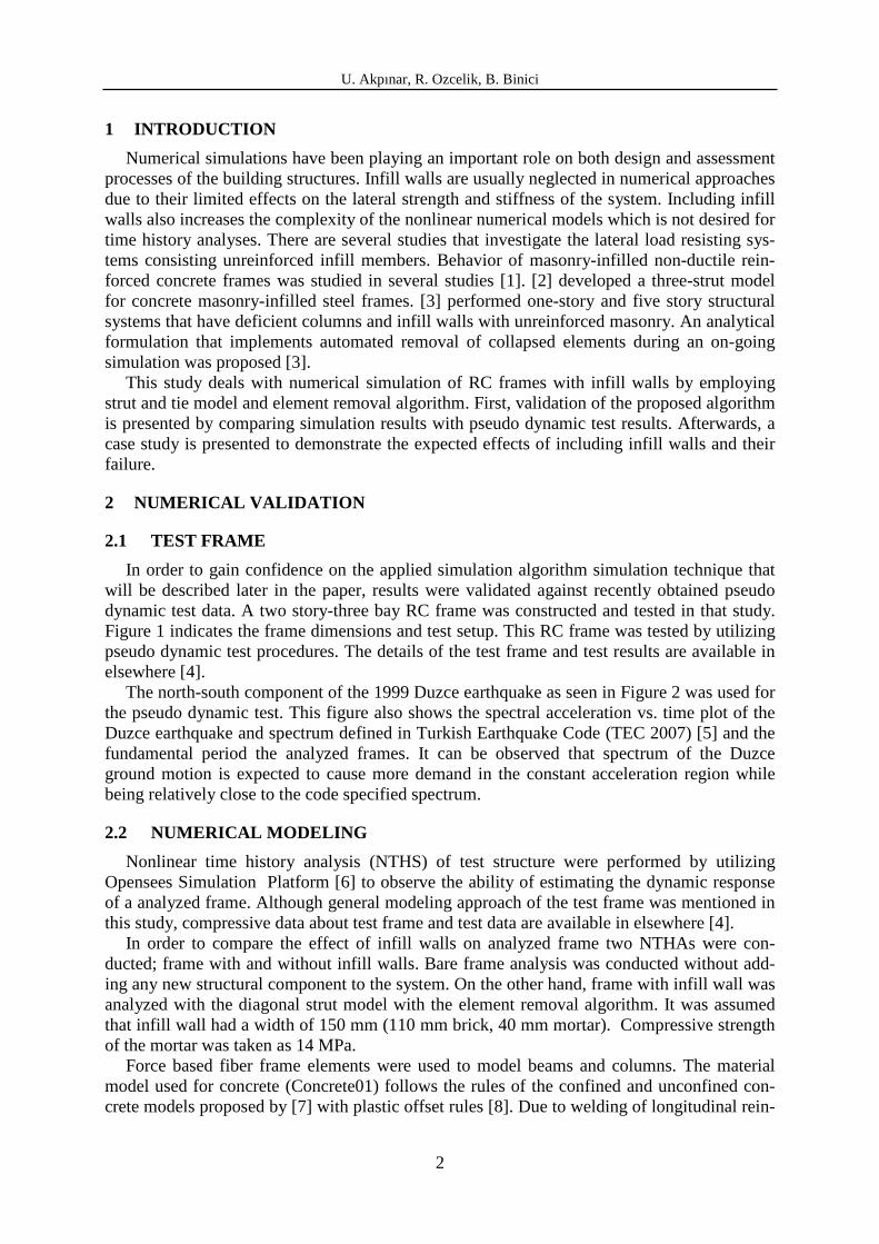
In order to gain confidence on the applied simulation algorithm simulation technique that will be described later in the paper, results were validated against recently obtained pseudo dynamic test data. A two story-three bay RC frame was constructed and tested in that study. Figure 1 indicates the frame dimensions and test setup. This RC frame was tested by utilizing pseudo dynamic test procedures. The details of the test frame and test results are available in elsewhere [4].
The north-south component of the 1999 Duzce earthquake as seen in Figure 2 was used for the pseudo dynamic test. This figure also shows the spectral acceleration vs. time plot of the Duzce earthquake and spectrum defined in Turkish Earthquake Code (TEC 2007) [5] and the fundamental period the analyzed frames. It can be observed that spectrum of the Duzce ground motion is expected to cause more demand in the constant acceleration region while being relatively close to the code specified spectrum.
2.2 NUMERICAL MODELING
Nonlinear time history analysis (NTHS) of test structure were performed by utilizing Opensees Simulation Platform [6] to observe the ability of estimating the dynamic response of a analyzed frame. Although general modeling approach of the test frame was mentioned in this study, compressive data about test frame and test data are available in elsewhere [4].
In order to compare the effect of infill walls on analyzed frame two NTHAs were con-ducted; frame with and without infill walls. Bare frame analysis was conducted without add-ing any new structural component to the system. On the other hand, frame with infill wall was analyzed with the diagonal strut model with the element removal algorithm. It was assumed that infill wall had a width of 150 mm (110 mm brick, 40 mm mortar). Compressive strength of the mortar was taken as 14 MPa.
Force based fiber frame elements were used to model beams and columns. The material model used for concrete (Concrete01) follows the rules of the confined and unconfined con-crete models proposed by [7] with plastic offset rules [8]. Due to welding of longitudinal rein-
U. Akpınar, R. Ozcelik, B. Binici
3
forcements to the foundation in the column ends, bond-slip was not observed at test frame. Hence, reinforcing steel was modeled using a bilinear elasto-plastic model (Steel 02) with a kinematic hardening slope of 1%. The infill walls were modeled using compression only truss elements connected to the diagonal nodes of the boundary frame.
Figure 1: Test frame and setup (adopted by [4])
150mm
150m
m
150 mm
200
mm
150mm
60m
m
600mm
AA
B
B
100mm
100mm
2000mm
1500mm
2500mm 1300mm 2500mm
Steel block
Infill wall
A-A Section Longitudinal Reinforcement; 4ϕ8
Transverse Reinforcement; ϕ4/100 mm
B-B Section Longitudinal Reinforcement; 4ϕ8
Transverse Reinforcement; ϕ4/100 mm
150 mm
150
mm
200
mm
600 mm
60 mm

U. Akpınar, R. Ozcelik, B. Binici
4
-0.4
-0.3
-0.2
-0.1
0
0.1
0.2
0.3
0.4
0 5 10 15 20 25
Gro
un
d A
cce
lera
tio
n (
g)
Time(sec)
0
0.5
1
1.5
2
2.5
3
0 0.5 1 1.5 2 2.5 3
Sa
(g)
Period (sec)
Duzce (1999)
TEC07 Zone 1TInfill= 0.33 sec
TBare= 0.81 sec
Figure 2: Duzce ground motion and spectrum
FrameConcrete Compressive
Strength (Mpa)Longitudinal Reinforcement
Yield Strength (MPa)Transverse Reinforcement
Yield Strength (MPa)Analized Frame 9.0 220 220Test Frame 7.4 330 290
Table 1: Mechanical properties of the materials.
Figure 3: Infill wall layout and analytical model of the test frame.
The material properties and relevant equations from ASCE/SEI-41 guidelines [9] were em-ployed. In this way it was possible to observe the success of estimating the natural period of the test structure with these stiffness values. Effective strut area for the infill walls was calcu-lated according to ASCE/SEI-41 guidelines and found as 0.025 and 0.021 m2 for the first and second stories using the following equations:
( ) inf4.0
1175.0 rha col−×= λ (1)
( ) 41
1 4
2sin
+=
incc
pinms
hIE
ttE θλ (2)

U. Akpınar, R. Ozcelik, B. Binici
5
Above, hcol is the column height, rinf is the diagonal length of infill panel, θ is the angle whose tangent is the infill height to length ratio, Ec and Ems are the modulus of elasticity of concrete and the plaster-infill composite and tin and tp are the thicknesses of brick units and the plaster. The modulus of elasticity of the plaster-brick composite, Esm, was computed as 10000 MPa from Binici and Ozcebe 2006 [10]:
st
pmininms t
tEtEE
+= (3)
where Ein and Em are the modulus of elasticity of the infill wall and mortar/plaster, and tin and tm are the thickness of the infill wall and mortar. Accordingly, Ein was taken as 7700MPa (550Fm) based on ASCE/SEI-41 recommendations and tu was calculated as 16200 MPa (4700√Fc) using ACI 318-05 [11] equation.
The observations made during the test showed that diagonal cracks formed in the central region of the infill in both directions. Later these cracks extended in a step pattern indicating the failure of bed joints along the diagonal. Consequently, compressive strength of the strut (Fcm) was computed from ASCE/SEI-41 assuming that bed-joint shear strength governs the strength of the diagonal strut either in the form of a diagonal crack or a single horizontal bed joint by using equations:
( )pinmvss ttLfV += (4)
( )θcosaVf sscm = (5)
in which Vss is the total shear resistance along the wall length, L is the length of the infill wall, fmv is the shear strength of bed mortar/plaster mix which was taken from ASCE/SEI-41 as 0.25 MPa for masonry in good condition. Popovics equation [12] was employed for the com-pressive stress-strain behavior of the infill struts (Concrete 04) as suggested by [13]. The strain at peak compressive strength and diagonal strut failure were taken as 0.002 and 0.004, respectively.
Although the infill diagonal strut fails in one direction in the numerical simulations, the strut in the opposite direction at the first story had still significant capacity and stiffness. Hence the frame could not deform in the opposite direction upon failure of only one diagonal strut. In order to overcome this modeling error, element removal algorithm as suggested by [3] was adopted. When the failure strain of the diagonal strut is exceeded in one direction, the struts in both directions are removed from the model. Upon element removal, internal forces were redistributed to achieve an equilibrium state at failure time. In this way, failure of the strut in one direction results in complete failure of the infill wall.
Nodes were constrained to act as rigid diaphragms for all stories. Lumped mass approach with a Rayleigh critical damping of 5% was utilized during the analyses by also incorporating the second order nonlinear geometric effects. The details of modeling and the properties of effective truss model are given in Figure 3. The NTHA results of the test frame indicate that the proposed model of the infill wall was able to capture the load deformation behavior (Fig-ure 4) in a fairly accurate manner. It can be observed that inclusion of the element removal algorithm is necessary in order to capture the damage state of the test frame at the verge of collapse.

U. Akpınar, R. Ozcelik, B. Binici
6
Figure 4: NTHA results of the test frame
3 CASE STUDY
3.1 FOUR STORY-THREE BAY RC FRAME
An exterior frame of a deficient existing 4-story RC building was analyzed with and with-out infill strut model to reflect the importance of infill modeling and element removal algo-rithm. The first floor plan view of this building is indicated in Figure 5. The evaluated 4-story 3-bay frame is given in Figure 5 where the complete details of the analyzed building are avail-able elsewhere [14]. The frame had 250x400 mm columns which were oriented in their strong axis for B-axis and their weak axis for A, C and D-axes. All the beam dimensions were 150x500 mm. Interior bay of the frame (B-C axes) were used for installing infill walls as truss members. Table 1 indicates the mechanical properties of the materials. Accordingly, uniaxial compressive strength of the concrete was 9 MPa and the yield strength of reinforcing steel was 220 MPa. Stirrup spacing was 260 mm for beams and 280 mm for columns with a clear cover of 25 mm. Beams, columns and further structural details are given in Figure 5.
3.2 NUMERICAL MODEL OF FOUR STORY-THREE BAY RC FRAME
The modeling approach of the case study was similar to that of test frame. It was assumed that infill wall had a width of 150 mm (110 mm brick, 40 mm mortar) which is same as width of beams in analyzed structure. Effective strut area for the infill walls was calculated accord-ing to ASCE/SEI-41 guidelines and found as 0.042 m2. Compressive strength of the mortar and the elastic section modulus of the infill wall were taken as 14 MPa and 10000 MPa, re-spectively. The analytical model is shown in Figure 6.
3.3 ANALYSIS RESULTS OF THE FOUR STORY-THREE BAY FRAME
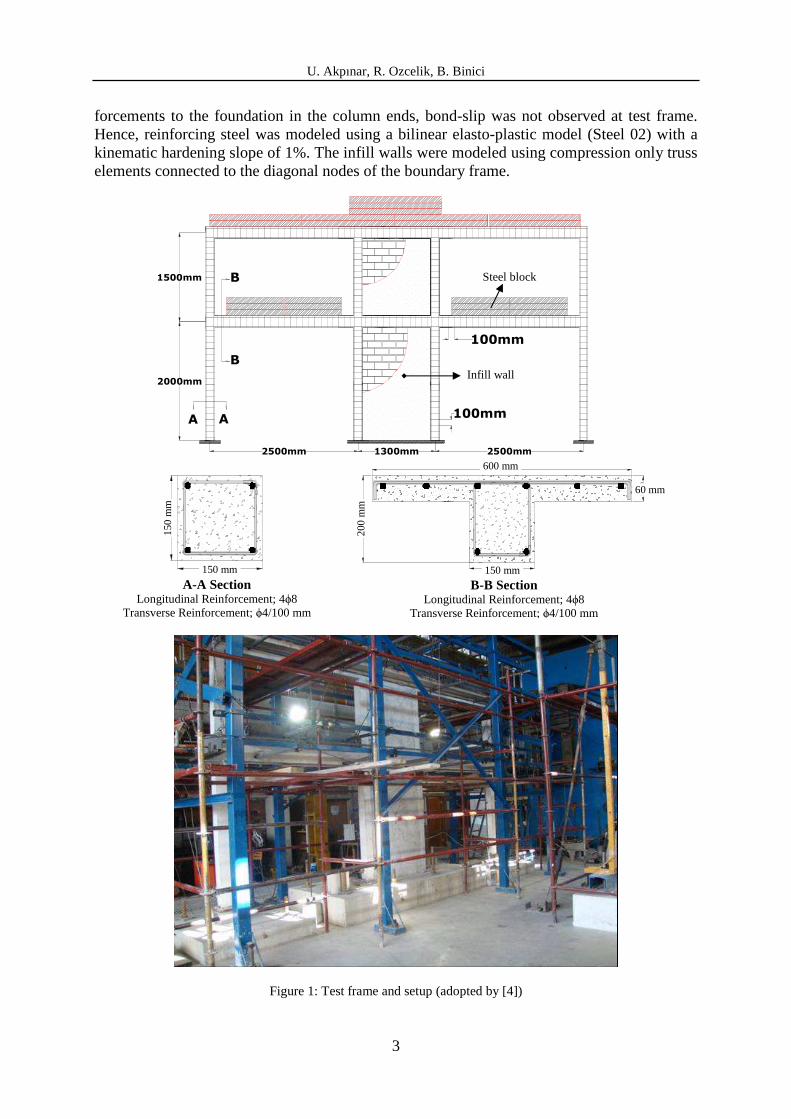
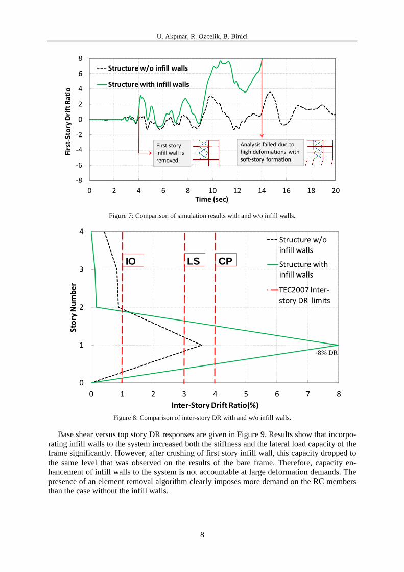
The NTHA results of the frames with and without infill walls are presented in Figure 7. For the analysis of the test frame with infill walls, the element removal algorithm was incor-porated. The structure excluding the presence of infill walls exhibited a peak first-story drift ratio (DR) of about 3.6%. However, the structure with infill walls experienced more than 8% DR upon automatically removing the wall struts from the system. Structure with infill walls suffered higher DRs than the structure without infill walls and finally it collapsed under the extreme first-story DR demands. Effect of soft-story formation could be seen more clearly in Figure 8.

U. Akpınar, R. Ozcelik, B. Binici
7
Figure 5: a) Analyzed building floor view, b) Analyzed 4-story frame, c) Beam and column section.
Figure 6: Infill wall layout and analytical model of the test and 4 story-3story frames.
According to results structure without infill walls satisfied inter story drift ratio (IDR) lim-its of TEC 2007 for the collapse prevention (CP) limit state and remained in the high damage region. Results reveal that neglecting infill walls for design purposes may not ensure designer to stay on the safe side for all the cases. The main difference between the results of two frames is the sudden collapse of the infill wall and change of dynamic properties of the test frame during the ground motion. The infill walls, although beneficial and control inter story drift deformations at low deformation demands, provide significant amplification of deforma-tions (1st story in this example) when sudden collapse of the infill wall occurs. The estimation of deformations when infill walls are neglected may not necessarily be on the safe side for design purposes.
270
0m
m27
00m
m27
00m
m27
00m
m
2700mm 3650mm 3750mm
A B C Db) a)
c) 150
500
400
250
Column, Axis B Longitudinal Reinforcement: 6ϕ12
Transverse Reinforcement: ϕ8/270mm
250
400
Column, Axis A, C, D Longitudinal Reinforcement: 6ϕ12
Transverse Reinforcement: ϕ8/270mm
Beam Longitudinal Reinforcement: 4ϕ12
Transverse Reinforcement: ϕ8/280mm
U. Akpınar, R. Ozcelik, B. Binici
8
-8
-6
-4
-2
0
2
4
6
8
0 2 4 6 8 10 12 14 16 18 20
Firs
t-S
tory
Dri
ft R
ati
o
Time (sec)
Structure w/o infill walls
Structure with infill walls
Analysis failed due to
high deformations with
soft-story formation.
First story
infill wall is
removed.
Figure 7: Comparison of simulation results with and w/o infill walls.
0
1
2
3
4
0 1 2 3 4 5 6 7 8
Sto
ry N
um
be
r
Inter-Story Drift Ratio(%)
Structure w/o
infill walls
Structure with
infill walls
IO LS CP
TEC2007 Inter-
story DR limits
+8% DR
Figure 8: Comparison of inter-story DR with and w/o infill walls.
Base shear versus top story DR responses are given in Figure 9. Results show that incorpo-rating infill walls to the system increased both the stiffness and the lateral load capacity of the frame significantly. However, after crushing of first story infill wall, this capacity dropped to the same level that was observed on the results of the bare frame. Therefore, capacity en-hancement of infill walls to the system is not accountable at large deformation demands. The presence of an element removal algorithm clearly imposes more demand on the RC members than the case without the infill walls.

U. Akpınar, R. Ozcelik, B. Binici
9
-250
-200
-150
-100
-50
0
50
100
150
200
250
-4 -3 -2 -1 0 1 2 3 4
Ba
se S
he
ar
Forc
e (k
N)
Top Story Drift Ratio (%)
Structure w/o infill walls
Structure with infill walls
107% Increase in lateral load capacity
Figure 9: Base shear versus top-story DR with and w/o infill walls.
Performance evaluation of the both frames led to similar results for the first story (Figure 10). For the case without infill walls 75% of the columns passed beyond CP performance limit at first story. However, for the case with infill walls, all the first story columns of the test frame passed beyond CP performance limit as expected. Incorporating infill walls in the NTHA also changed the response on the upper stories. Frame without infill wall mainly ex-perienced damage at the interior columns of first and second stories and exterior beams of first story. Violation of CP performance limit was observed for these beams. For the case with infill walls, formation of soft story oriented the distribution of damage to first story and pre-vented upper stories experiencing any significant damage. Both of the systems did not satisfy the overall performance criteria of TEC 2007 and found to be in collapse region.
Figure 10: Performance evaluation of RC frame members with and w/o infill walls.
4 CONCULUSIONS
For assessment purposes, contribution of infill walls may be included to have a better esti-mation of displacement demands. Results showed that ASCE-SEI-41 recommendations for strut modeling may lead to satisfactory estimation along with the use of element removal al-gorithm. The formation of a soft story mechanism was found to be better simulated with the
CPCP
CPCP
CPCP
CPCP
IOIO
IOIO
CPCP
IOLS
LSLS
IO
CPCP
IOIO
IOIO
CPCP
CP LS
IO IO
CP
IO
a) Without infill walls b) With infill walls

U. Akpınar, R. Ozcelik, B. Binici
10
use of such a removal algorithm. Performance evaluation of the 4 story-3 bay frame showed that after failure of the infill wall, all the first story columns passed the CP limit state and sus-tained heavy damage due to excessive IDR levels. As a result, for design purposes neglecting infill walls may not always lead to safe design or assessment results.
5 AKNOWLWEDGE
The research discussed in this paper was conducted at Middle East Technical University (METU)-Structural Mechanics Laboratory. Funding provided by TÜBİTAK (project no: 106M493) is greatly appreciated.
REFERENCES
[1] G. Al-Chaar, M. Issa, S. Sweeney, Behavior of Masonry-Infilled Nonductile Rein-forced Concrete Frames,. Journal of Structural Engineering, 128, No. 8, 2002.
[2] W. El-Dakhakhni, F. M. Elgaaly and A. A. Hamid, Three-Strut Model for Concrete Masonry-Infilled Steel Frames. Journal of Structural Engineering, 129, No. 2, 2003.
[3] K. Talaat, K.M. Mosalam, Modeling Progressive Collapse in Reinforced Concrete Buildings Using Direct Element Removal. Earthquake Engineering & Structural Dy-namics, 38(5), 609-634, 2009.
[4] E.G. Kurt, B. Binici, O. Kurc, E. Canbay, U. Akpinar and G. Ozcebe, Seismic Perform-ance of a Reinforced Concrete Test Frame with Infill Walls, Earthquake Spectra, article in press, 2010.
[5] Turkish Code for Buildings in Seismic Zones (TEC 2007). Ministry of Public Works and Settlement Ankara, Turkey, (In Turkish), 2007.
[6] S. Mazzoni, H. McKenna, M.H. Scott, G.L. Fenves, OpenSees Manual. Pacific Earth-quake Engineering Research Canter, http://opensees.berkeley.edu, 01/09/2010.
[7] D.C. Kent, R. Park, Flexural Members with Confined Concrete. Journal of Structures Division, ASCE, ST7, 97, 1969–1990, 1971
[8] I.D. Karsan, J.O. Jirsa, Behavior of Concrete under Compressive Loading. Journal of Structural Division, ASCE, ST12, 95, 2543-2563, 1969.
[9] American Society of Civil Engineers, “Seismic Rehabilitation of Existing Buildings, Report”, No. ASCE/SEI 41-06, Reston, Virginia, 428, 2007.
[10] Binici, B. Ozcebe, G, Analysis of infilled reinforced concrete frames strengthened with FRPs, Advances in Earthquake Engineering for Urban Risk Reduction, Editors Wasti, S.T. and Ozcebe, G. NATO Science Series, Earth and Env. Sciences, 66, 455-471.
[11] American Concrete Institute (ACI 318-05), “Building Code Requirements for Structural Concrete and Commentary”, ACI Committee 318, 430 pp, 2005.
[12] S. Popovics, A Review of Stress–Strain Relationships for Concrete. American Concrete Institute Journal, 67(3) pp. 243–248, 1975.
[13] A. Madan, A.M. Reinhorn, J.B. Mandar, R.E. Valles, Modeling of Masonry Infill Pan-els for Structural Analysis. Journal of Structural Engineering, ASCE, 123 (10):1295-1302, 1997.

U. Akpınar, R. Ozcelik, B. Binici
11
[14] Binici, B., Ozcebe, G. and Ozcelik, R, Analysis and design of FRP composites for seis-mic retrofit of infill walls in reinforced concrete frames. Composites Part B: Engineer-ing, 38(5), pp. 575-583.